1. Introduction
Autonomous underwater vehicles (AUVs) are indispensable transport carriers and observation nodes for the exploration and management of oceans. An AUV not only has delivery capability but can also be equipped with sonar, manipulators, and various functions detection devices or sensors, to perform environment monitoring, resource extraction, and sampling. Due to the limited internal space and weight, the onboard battery cannot sustain the long-term continuous operation of underwater vehicles in deep-sea environments. At present, battery replacement and wet-plug charging are the leading employed power replenishment approaches for AUVs [
1]. The former method involves salvaging and recovering the vehicle, replacing the battery, all the procedures highly depend on manual operations. The latter approach involves docking and installing a wet-pluggable interface, wear issue, the strict demand on docking and manipulating process are the vital challenges.
Wireless power transfer (WPT), based on electromagnetic induction, has emerged as a novel means for power transmission in recent years [
2,
3]. As a non-contact power transfer technique, where the transmitting and receiving sides do not have physical contact and can be separated independently [
4]. This offers strengths such as convenience, safety, and ease of maintenance [
5,
6]. In recent decades, WPT technology has gradually matured and is widely utilized in electric vehicles, biomedical implants, industrial manufacturing, smart homes, and other fields [
7,
8,
9,
10]. Recently, wireless power transfer technology was attempted to apply in power supply for underwater vehicles [
11,
12,
13].
The misalignments, including axial, rotational, and inclined offsets, caused by docking errors, ocean current, and movement posture deviation, are the primary obstacles faced by WPT technology. The magnetic coupler is a key component of the WPT system. The system’s output power and transmission efficiency are affected by the magnetic coupler [
14,
15,
16]. Various magnetic couplers have been proposed for the WPT system of AUVs with a cylindrical structure. Yan et al. [
17] designed a coil-wound structure suitable for the cylindrical hull of AUV, integrating ferrite material on the back of the coil to enhance coupling and suppress electromagnetic radiation. The design provided certain resistance to rotational misalignment within the 0–45° range. A 1000 W system was built, achieving 95% power transfer efficiency with fluctuations below 2%. Wang et al. [
18] proposed a novel pendulum-type magnetic coupler, where the transmitting coil was a common D-shaped arc coil, and the receiving coil was a multi-layer solenoid wound around a magnetic core, significantly increasing coupling. Nanocrystalline material at the bottom was added to concentrate the magnetic flux, while nanocrystalline material at the top was employed for electromagnetic shielding and enhancing coupling. Stable output was achieved within the ±30 mm rotational and axial misalignment range, with dc-dc efficiency maintained at over 95% and efficiency fluctuation below 1%. A dipole coil-type magnetic coupler with a circumferential coupling means was designed in [
19], the magnetic coupler has capable of limiting the magnetic flux. The 630 W underwater experimental system was conducted, where the output power reached a maximum of 950 W within a rotational misalignment range of 10°, with a minimum efficiency of 87.08%. The above proposed magnetic couplers could be adapted to the cylindrical or arc-shaped structure of AUVs and charging station. However, the insufficient resistance to rotational misalignment was the main weakness that limited the application. As a result, it struggled to dramatically decrease power transmission efficiency when large-angle rotational misalignments occur.
In reference [
20], a solenoid-double combination planar coil coupling structure was designed. Compared to the single-pole planar coil, this structure improves the axial misalignment tolerance. In seawater environment, the power fluctuation was less than 4.15%, and the transmission efficiency fluctuation was below 6.74% within an axial misalignment range of 40 mm. In order to mitigate electromagnetic interference on electronic devices of AUV, a three-phase transmitting coil, consisting of three identical transmitting coils, each fed with 120° degree phase difference excitation currents, was proposed in [
21]. Under rotational angles ranging from 0 to 25°, the misalignments tolerance exceeded that coaxial circular coil with same size. However, when the rotation misalignments exceeded 25°, the mutual inductance sharply drops, and system stability can only be restored through mechanical adjustments. Zeng et al. [
22] introduced a transmitting coil composed of solenoid and conical coils. The concave magnetic field generated by the conical coil is complemented by the convex magnetic field created by specific turns and spacing of the planar solenoid coil, resulting in a uniform magnetic field. A transmitting coil composed of multiple solenoid coils arranged in alternating directions, which enhances tolerance to axial misalignment, was proposed in [
23]. A magnetic coupler consisting of a single-layer arc-shaped rectangular transmitting coil and a double-layer arc-shaped receiving coil was introduced by Zhang et al. [
24]. The transmitting coil is capable of expanding and contracting in synchronization with the charging platform, thereby accommodating a wide range of rotational misalignment. However, this design necessitates a complex mechanical control system. Li et al. [
25] proposed an LCC-N compensation topology that employed fewer components on the secondary side. By adjusting the value of the switching capacitor on the primary side, the system can maintain a stable output current under misalignment conditions. However, this method requires sampling the primary-side current and voltage, as well as estimating the mutual inductance under misalignment. However, the above-mentioned magnetic coupler designed did not take axial, rotational, and inclined misalignments into account, resulting in lower adaptability to dynamic marine environment.
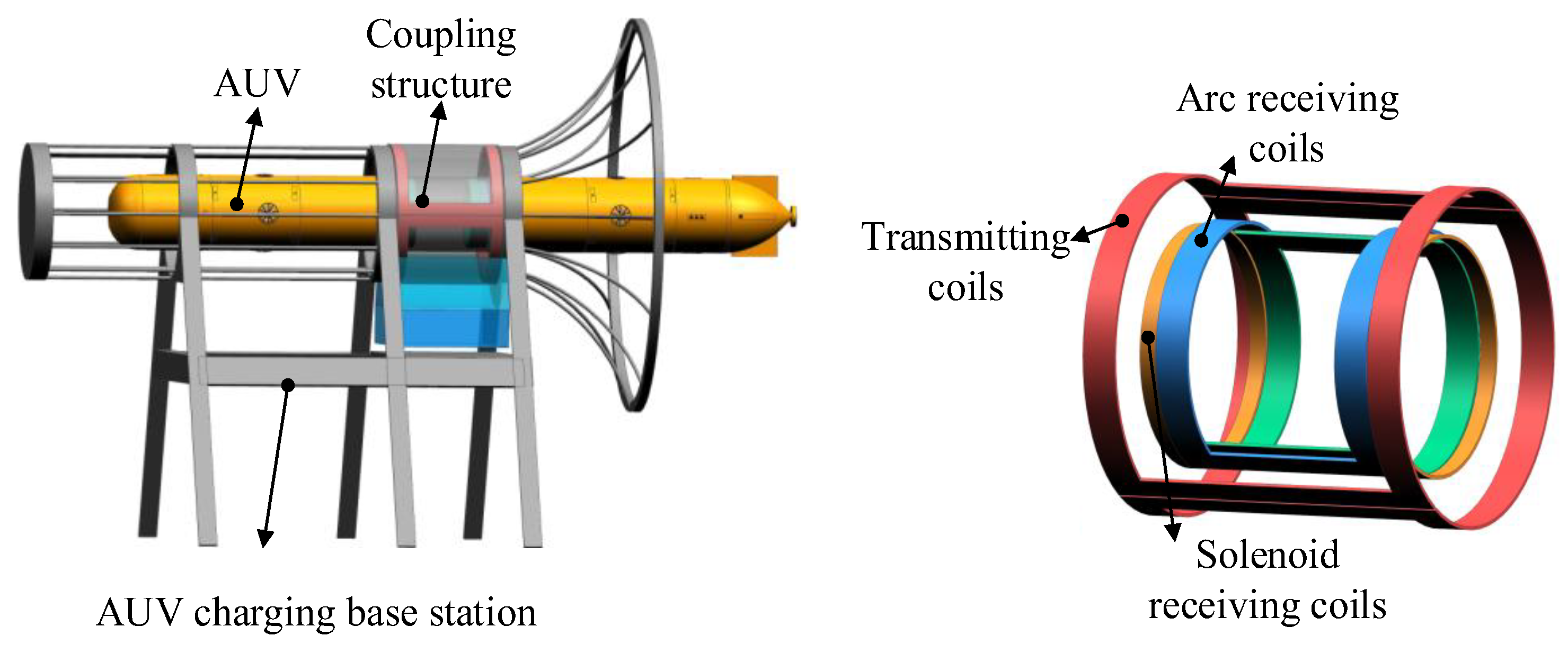
To address the composite and complex misalignment AUVs faced under ocean environment, this paper proposes a hybrid magnetic coupler. The transmitting coil is composed of two identical arc-shaped rectangular coils, and the receiving coil consists of two overlapped arc-shaped rectangular coils combined with two anti-series connected solenoid coils wound on both sides. The arc-shaped rectangular coils are intended to capture magnetic fields oriented radially outward from the center, whereas the solenoid coils are used to capture axial magnetic fields. The proposed magnetic coupler is shown in
Figure 1. The transmitting coil is fixed to the seabed charging station, while the arc-shaped rectangular coils and solenoid coils are connected in series and wound in the hull of AUVs. The effects of various parameters on the misalignment tolerance and coupling coefficient of the magnetic coupler are simulated using COMSOL5.5 software. Based on the analysis, the parameters of the magnetic coupler are optimized. Additionally, a 300 W experimental prototype is constructed to validate the proposed magnetic coupler.
2. Magnetic Coupler Design
The DD coil is a typical type of bipolar coil, in which two identical sub-coils are employed, and they are winded in opposite directions, thus a bipolar magnetic field is be generated. The DD coil magnetic coupler exhibits excellent misalignment tolerance, particularly when lateral misalignments occur, thus, it is widely employed in WPT system of electric vehicle [
26]. This paper initially selected the arc-shaped DD-DD coil magnetic coupler for the design. The mutual inductance fluctuation of the arc-shaped DD magnetic coupler during rotation is shown in
Figure 2.
θ represents the rotation angle. As the rotation angle increases, the mutual inductance first decreases and then increases, with the mutual inductance approaching zero when the receiving coil is rotated to 90°. This point is referred to as the zero-coupling point of mutual inductance.
To eliminate the instability in power transmission caused by the zero-coupling point, the direction of current in the coils is altered to a consistent winding orientation. The mutual inductance variation curve of the modified magnetic coupler within a 180° rotation range is shown in
Figure 3. Compared to the arc-shaped DD coil, the modified magnetic coupler does not exhibit a zero-coupling point, and the mutual inductance fluctuations are significantly reduced. However, when the receiving coil experiences rotational misalignment and moves away from the aligned position, the mutual inductance decreases. The mutual inductance remains stable when the rotation angle ranges from 30° to 150°. Furthermore, the maximum mutual inductance between DD coils with the same winding orientation significantly decreases, thereby reducing the coupling capability of the magnetic coupler.
Considering the above-mentioned issues, the proposed magnetic coupler, as shown in
Figure 1, features a transmitting coil with the same winding orientation as the DD coil. The receiving coil consists of a DD coil with the same winding orientation and two anti-series connected solenoid coils. To mitigate mutual inductance fluctuations when the rotation angle ranges from 0° to 30°, the arc-shaped receiving coil is overlapped.
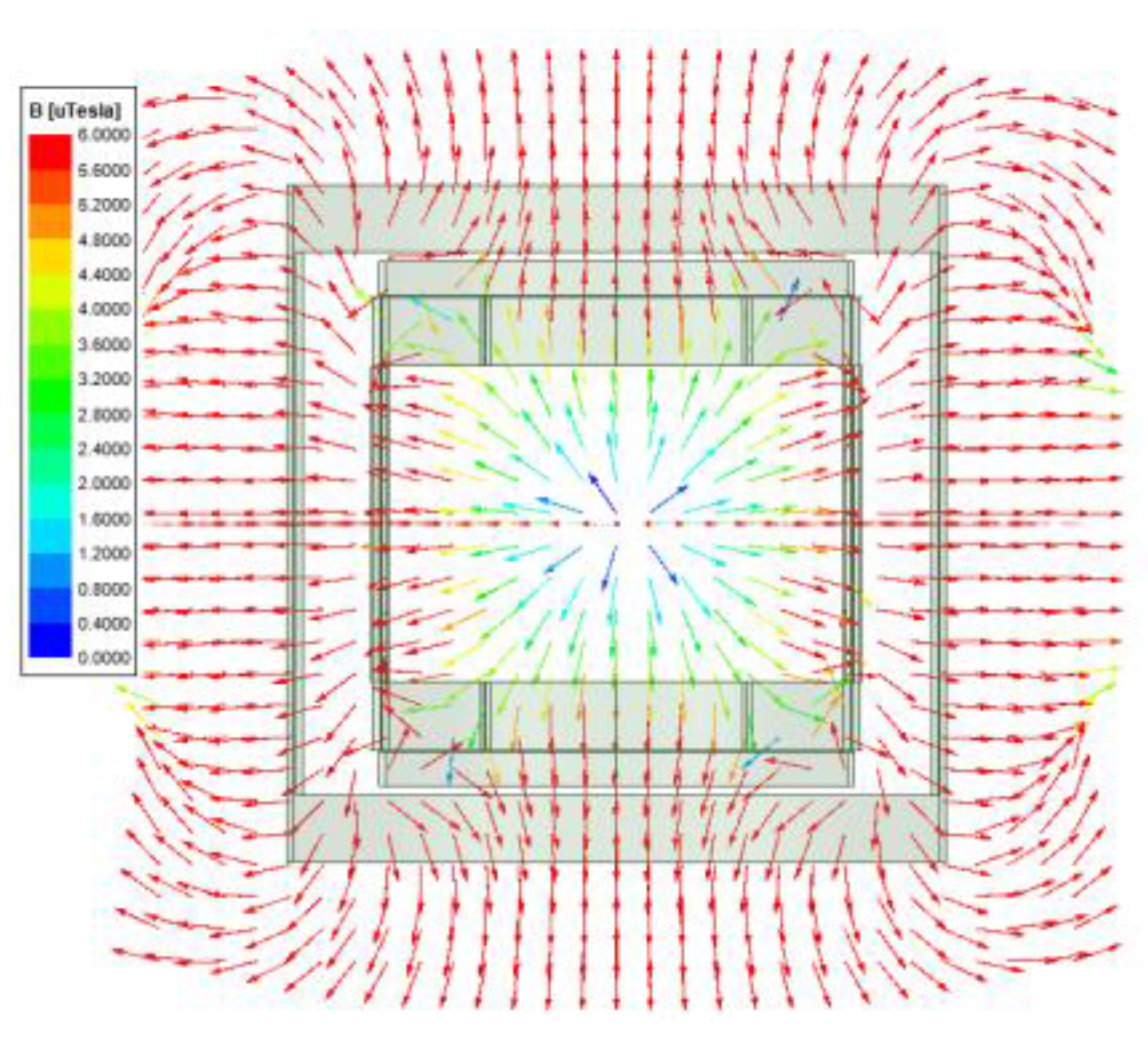
Figure 4a,b illustrate the magnetic field vector diagrams in the XOY plane when the receiving coil at aligned position (0°) and rotation angle of 45°, respectively. It can be observed that the transmitting coil primarily generates a magnetic field directed towards the center of the circle in the XOY plane. At the junction of the two coils, the magnetic field direction points outward from the center. The arc-shaped coil mainly picks up magnetic flux directed towards the center. However, when the arc-shaped DD coil undergoes rotational misalignment, the receiving coil picks up additional magnetic flux directed outward from the center through the junction with the transmitting coil. This results in a decrease in the total magnetic flux through the receiving coil. With the rotation angle below 180°, the captured flux remains relatively unchanged. Considering the rotational symmetry structure of the magnetic coupler, we only explore the misalignment tolerance within 180°. The overlapped pickup area can be enlarged as the length of the arc-shaped coil increases, allowing a more outward-directed flux from the center to be captured when aligned. However, further increasing the coil length results in more flux directed towards the center be captured. When the overlapping receiving coil undergoes rotational misalignment, the flux directed towards the center would be increased. Therefore, by optimizing the length of the overlapping section, the mutual inductance of the magnetic coupler can be adjusted both in the aligned and misaligned states, reducing the mutual inductance fluctuations caused by the rotation of the receiving coil. This will be discussed in detail in
Section 3.
The magnetic field vector diagram in the XOZ plane is shown in
Figure 5. The transmitting coil generates a magnetic field directed towards the center in XOZ plane, which consists of both horizontal and vertical components, with the field strength being weaker near the center. Based on the above analysis, the arc-shaped DD overlapping coils can effectively capture the horizontal magnetic flux components. A pair of anti-series connected solenoid coils are positioned at each end of the arc-shaped coil. By ensuring that the magnetic flux components from the two solenoid coils are equal in magnitude but opposite in direction, the hybrid receiving coil can effectively capture the vertical and horizontal magnetic flux components, further enhancing the coupling capability.
3. Optimization of Magnetic Coupler Structure Parameters
Based on the dimensions of AUVs and its charging station, the diameter of the transmitting coil is set to 280 mm, and the height is set as 300 mm, the radius of the receiving coil is set to 200 mm, and the height of the curved DD receiving coil is set as 200 mm. To simplify the optimization of the overlapping section length of the arc-shaped DD receiving coil, this process is transformed into an optimization of the central angle of the arc-shaped DD coil, as shown in
Figure 6a.
λ is the central angle of arc-shaped DD coil.
The mutual inductance between the transmitting coil and the receiving coil as a function of the central angle of the arc-shaped DD coil is shown in
Figure 6b. It can be inferred that when the magnetic coupler is aligned, the mutual inductance first decreases and then increases as the central angle λ grows. However, within the rotational misalignment range of 30° to 150°, the mutual inductance continues to increase as the central angle
λ expand. It is important to note that changes in the central angle
λ do not affect the mutual inductance fluctuation within the misalignment range. This behavior is consistent with the analysis of mutual inductance variation resulting from changes in the overlapping section size and the corresponding magnetic flux absorption, as discussed in
Section 2.
The coupling coefficient
k is denoted as
where
M is the mutual inductance of magnetic coupler,
LT and
LS are the self-inductance of transmitting coil, receiving coil, respectively.
Define the mutual inductance fluctuation Δ
M as
where
Mmax and
Mmin are the maximum and minimum mutual inductance of magnetic coupler, respectively.
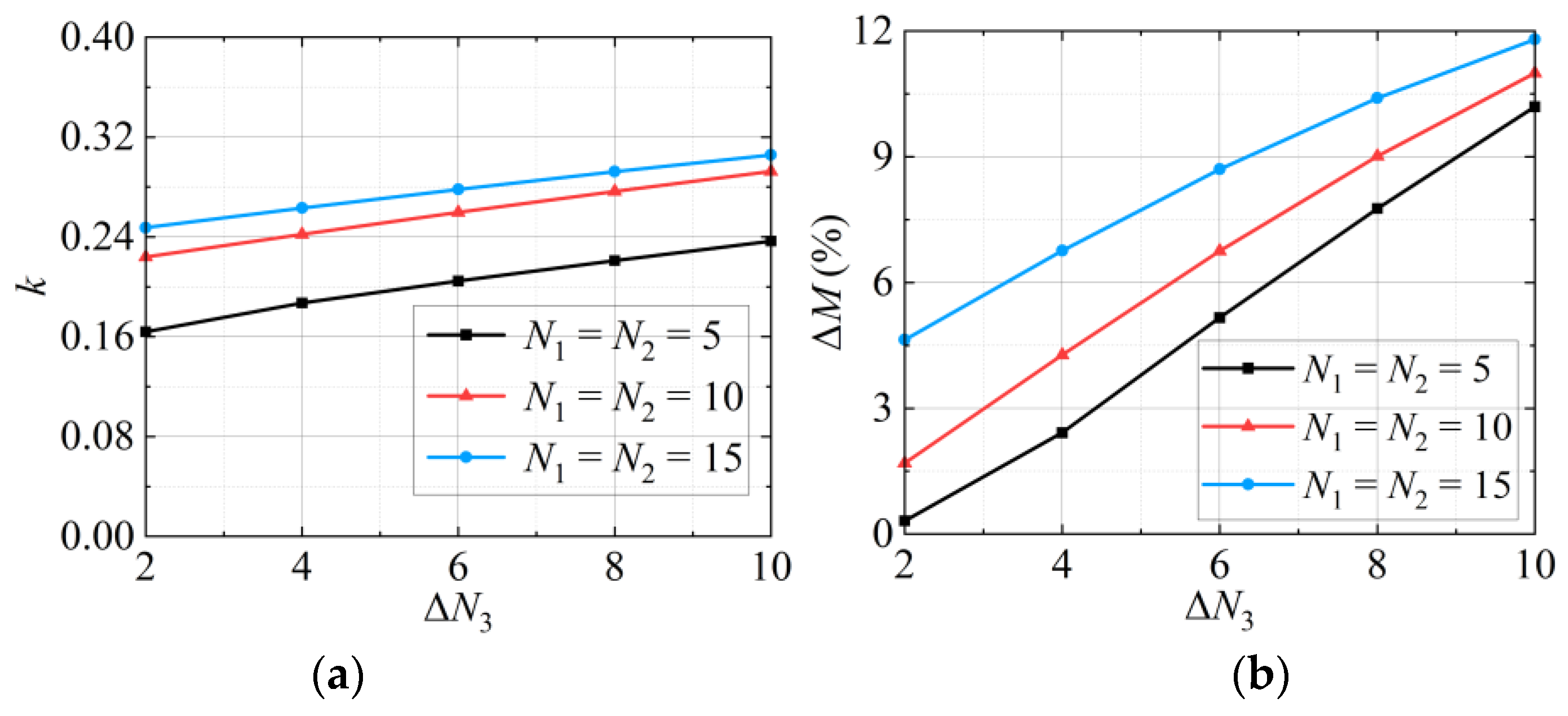
Figure 7 exhibits the coupling coefficient
k and the mutual inductance fluctuation Δ
M vary with the number of turns of solenoid coil
N3 when the axial misalignment increases from 0 to 40 mm, where
k and Δ
M are calculated from Equations (1) and (2). Although the value of
k increases with
N3, the Δ
M also increases as
N3 increases. This indicates that the increase of
N3 enhances the coupling capability of the coupler, it also reduces the misalignment tolerance of the coupler. Under the axial misalignment of 0 to 40 mm, both
k and Δ
M increase with the growth of the transmitting coil turn number
N1 and the arc-shaped DD receiving coil turn number
N2, while the increasing rate of
k gradually diminishes.
Based on the principles of minimal mutual inductance fluctuation and maximum coupling coefficient
k, the design and optimization flowchart of the magnetic coupler is shown in
Figure 8. Considering the dimensional constraints of the coils imposed by the AUV and its charging station, as well as the requirements for cost limit, the number of turns cannot be infinitely large, and the overlapped length of the arc-shaped receiving coil must not be excessive. The maximum values for
N1,
N2,
N3, and the central angle
λ are set to 15, 15, 10, and 220°, respectively. The initial values for
N1,
N2,
N3 and the central angle
λ are set to 5, 5, 2, and 180°. To ensure the stability of the system’s power transmission, the mutual inductance fluctuation Δ
M1 is below 5%. The increasing step of central angle
λ set as 10°. For the values of
N1,
N2, and
λ that meet the design requirements, the coupling coefficient and axial misalignment mutual inductance fluctuation are calculated for different
N3 values at the aligned position. A set of parameter combinations is then obtained. To reduce the number of simulations and simplify the optimization process,
N1 and
N2 are set to the same value, and after each simulation, both values are incremented by 1. The optimization results of
N1,
N2,
N3, and
λ are 10, 10, 5, and 200°, respectively.
4. The System’s Output with LCC-S Topology
The LCC-S compensation topology features low voltage stress on the primary-side compensation capacitors and requires only a single compensation capacitor on the secondary side, which is advantageous for achieving the lightweight design requirements of AUVs. The LCC-S compensation topology utilized in this paper is shown in
Figure 9. It includes a DC power source
Uin, an inverter (
S1–
S4), a transmitting coil
LT connected to a primary compensation network, a receiving coil
LS with series compensation, a bridge rectifier (
D1–
D4), and a DC load
RL.
LF is the primary-side compensation inductor.
LT, and
LS represent the self-inductances of the respective coils.
CF,
CT, and
CS are the compensation capacitors.
RT and
RS are the coil resistances.
IF,
IT, and
IS are the corresponding loop currents.
UT is the DC-side voltage of the inverter,
U1 is the AC-side voltage of the rectifier, and
UL is the voltage across the load.
It can be derived based on the fundamental wave analysis method [
27].
The system’s resonant angular frequency satisfies
Neglecting (3) and (4), it can be derived based on Kirchhoff’s law.
where
MTR represents the mutual inductance between the transmitting coil and the receiving coil.
The output voltage
UO and output power
P can be expressed as
5. Experimental Verification
To verify the feasibility of the proposed magnetic coupler, a 300 W experimental prototype was developed. As shown in
Figure 10, the prototype consists of a DC power supply, an inverter, a compensation network, a transmitting coil, a hybrid receiving coil, a rectifier, an electronic load, an oscilloscope, and a power analyzer. The self-inductance and mutual inductance were measured by LCR meter, and the oscilloscope was employed to display the waveforms of input/output voltage and current, the output power and power transmission efficiency could be acquired by the power analyzer. The electrical parameters for the experiment are listed in
Table 1.
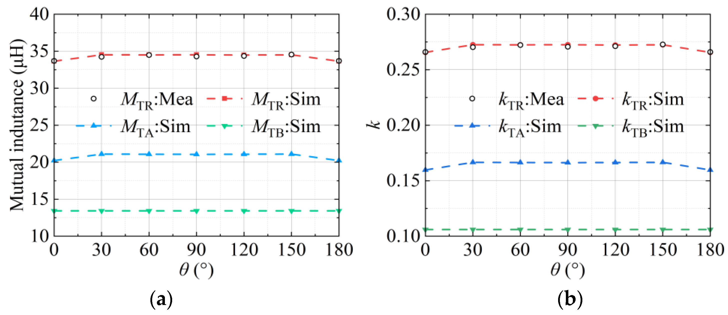
The variation in mutual inductance when the rotation angle ranges from 0° to 180° is shown in
Figure 11a.
MTR represents the total mutual inductance between the magnetic coupler,
MTA represents the mutual inductance between the transmitting coil and the arc-shaped DD coil, and
MTB represents the mutual inductance between the transmitting coil and the solenoid coil. Since the arc-shaped DD coil and the solenoid coil are wound with a single wire,
MTA and
MTB cannot be directly measured in the experiment; thus, both
MTA and
MTB in the figure are based on simulation data. From the figure, it can be observed that the overall mutual inductance,
MTR, remains stable during rotation. The measured result is matched with the simulation values. The maximum Δ
MTR is 2.3%. The mutual inductance fluctuation primarily occurs when the receiving coil deviates from the aligned position with angle of 0° to 30°. The simulation data show that
MTB remains stable across the entire misalignment range, and the variation in
MTR follows the same trend as
MTA.
Figure 11b displays the variation in the coupling coefficient when the rotation angle increases from 0° to 180°. The trend of the coupling coefficient change corresponds to the mutual inductance variation shown in
Figure 11a, with the minimum
kTR value of 0.266.
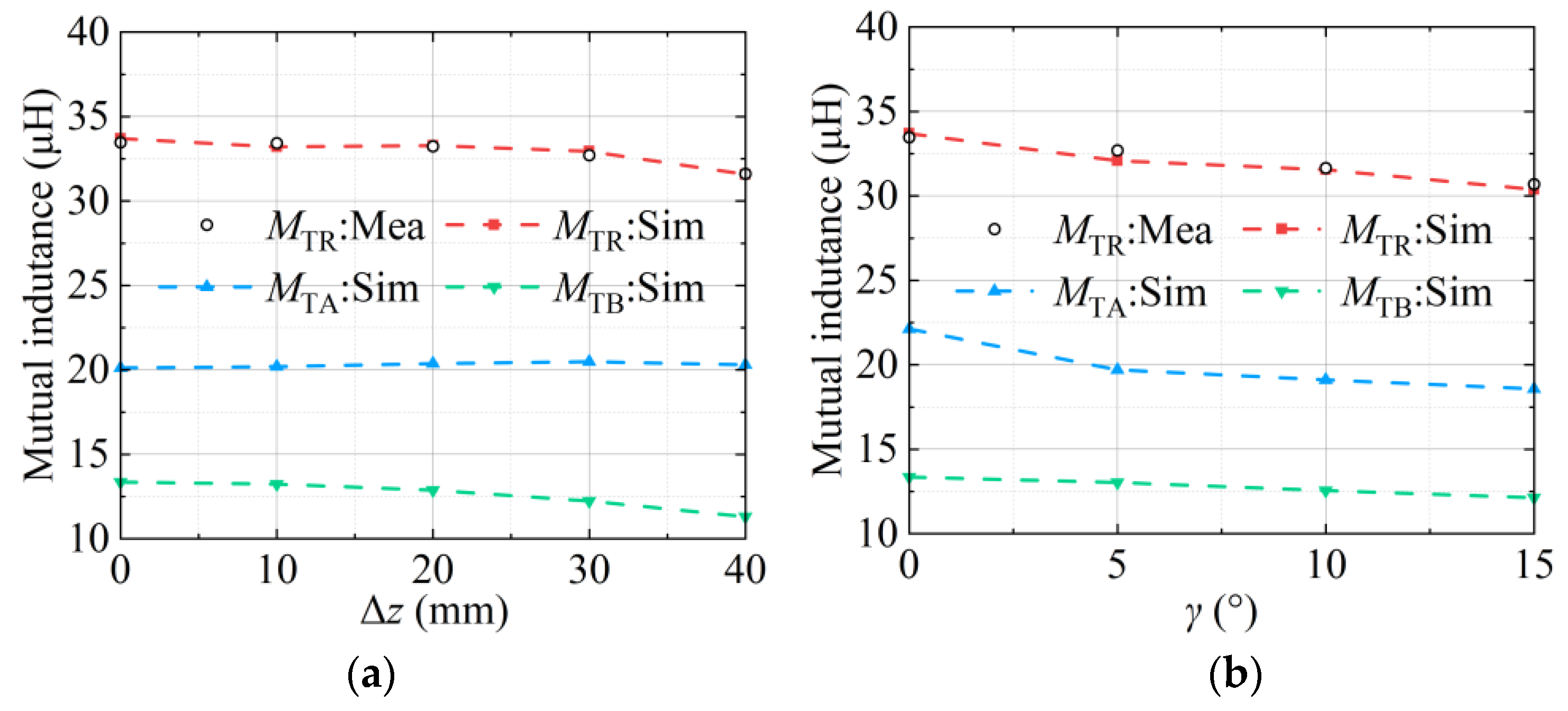
Figure 12a illustrates the variation in mutual inductance of the proposed magnetic coupler as the axial misalignment ranges from 0 mm to 40 mm.
MTR decreases as misalignment distance increases, with a maximum mutual inductance fluctuation Δ
MTR of 6.3%.
Figure 12b shows the variation in mutual inductance of the proposed magnetic coupler under the tilt misalignment range of 15°. Mutual inductance fluctuation
MTR decreases as the misalignment angle increases, with a maximum Δ
MTR of 9.8%.
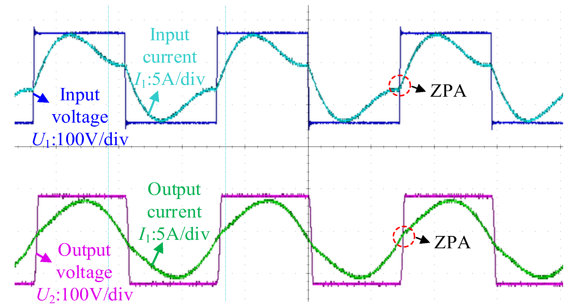
The voltage and current waveforms on the primary and secondary sides when the system is aligned are shown in
Figure 13. It can be observed that both the primary and secondary sides have achieved a resonant state, and zero phase angle (ZPA) operating characteristics are exhibited. The output power is rated at 300 W, with a transmission efficiency of 92.162%. A screenshot from the power analyzer is shown in
Figure 14.
Figure 15 shows the variations in output power and power transmission efficiency when the system is misaligned. The trends in output power and power transmission efficiency follow the same pattern as mutual inductance. The system demonstrates strong resistance to rotational misalignment. The output power remains around 300 W, while the power transmission efficiency stays above 92.1%. However, when axial or inclination misalignments occur, both output power and power transmission efficiency gradually decrease. The minimum output power values are 282.8 W and 260 W, while the minimum transmission efficiencies are 91.78% and 91.6%, respectively. However, due to the eddy current loss in seawater, the power transmission efficiency would degrade. Fortunately, the eddy current loss is proportional to the operation frequency, according to references [
28,
29]. In this research, the operation frequency is selected as 85 kHz, the eddy current loss is relatively slight under this frequency. As reported by the studies in [
30,
31], the power transmission efficiency would degrade by 1%~2% when transitioning from air to underwater environments.
Figure 16 shows the voltage and current waveforms on the DC side when the resistance load is changed from 35Ω to 30Ω. As the resistance decreases, the output current increases while the output voltage remains relatively unchanged, demonstrating the voltage regulation characteristics of the LCC-S compensation topology.


 ,
, 


