1. Introduction
The ship hull plates are typically composed of complex double-curved surfaces, making curved plate forming an indispensable process in shipbuilding. The processing of these curved plates usually involves line-heating or local cold bending, with the methods largely determined by manual experience. Additionally, these processes are often carried out manually, leading to low production efficiency. For such complex processing conditions, workers face challenges including long training periods, high labor intensity, and poor working environments [
1].
Complex curved surfaces are known as non-developable surfaces. Mathematically, non-developable surfaces have a nonzero Gaussian curvature and cannot be transformed from a plane into a curved surface via isometric deformation. In engineering, it is impossible to deform a plane into a non-developable surface without local in-plane stretching or shrinking. Consequently, forming processes for complex curved surfaces require the simultaneous application of bending and in-plane deformation to the material.
To enhance the automation and intelligence of shipbuilding processes, research has been conducted on the mechanisms of complex curved plate forming and the forming equipment. Forming equipment can generally be classified into two categories: variable-mold integral forming methods [
2,
3], and mold-free incremental forming methods with localized loading [
4,
5].
Integral forming equipment primarily consists of a hydraulic punch array. By adjusting the height of each punch, a mold representing the curved surface is created. Bending deformation is applied by controlling the downward displacement of individual hydraulic punches, and in-plane loads are introduced concurrently. However, since the punches cannot directly control the in-plane loads, managing in-plane deformation becomes challenging. This limitation makes the method less suitable for processing larger plates or plates with higher curvature and complicates the implementation of automated and intelligent equipment.
Localized loading forming equipment is mainly represented by line-heating forming equipment and cold-press forming equipment. Line-heating forming equipment can apply both in-plane and bending deformations along the processing path. However the efficiency of applying bending deformation is relatively low. In contrast, cold-press forming equipment relies on a variety of cold-press tools. This often necessitates frequent tool changes, such as switching between rolling, point pressing, and bending tools. These tools are typically heavy, rely on manual operation, making automated production nearly unattainable.
Based on the characteristics of various pieces of forming equipment and considering processing cost factors, a new integrated hot-and-cold forming technology has been proposed. This method aims to develop automated and intelligent equipment. It replaces traditional line-heating processes with electromagnetic induction heating and combines this with press rolling, effectively integrating the advantages of hot and cold processing tools. This approach provides a flexible and efficient means of producing complex curved surfaces, meeting the diverse deformation demands of such surfaces. The method also facilitates the advancement of automated intelligent manufacturing equipment.
In this forming method, the relationship between localized loading and the overall deformation response is critical. This connection is fundamental to defining processing route and is a key condition for achieving automated plate forming production.
For ship hull plates, typically categorized as thin plates, deformation and strain are directly related to the shape changes. Thin plate theory shows that strain represents the geometric relationship, effectively bypassing the complex nonlinear relationship between stress and strain. From another perspective, strain can serve as a characteristic parameter for processing tool conditions. Strain analysis acts as a bridge to establish a correlation between plate deformation shapes and tool processing parameters using strain as the central parameter. Moreover, the numerical representation of the relationship between the target plate shape and the tool’s processing behavior makes automated intelligent forming equipment feasible. Thus, generating processing route based on strain analysis becomes the primary focus of the forming process research. The study of processing route based on strain analysis can be broadly divided into the following aspects: (1) obtaining the strain distribution for forming a plane into the target shape; (2) discretizing the continuous strain distribution into processing paths; (3) establishing and refining the relationship between strain path distribution and the target shape; (4) engineering practicality and validation of ideal strain distributions; (5) rapid generation of strain path distributions and overall forming verification for the target shape.
For obtaining the strain distribution during the transformation from a plane to a target shape, several studies have been conducted. Surface flattening is a common method for acquiring strain. Ueda proposed a method using elastic finite element analysis for surface flattening [
6]. This method involves applying enforced displacements to obtain the strain distribution after flattening. By iteratively applying initial stresses, they minimized the tensile strain in the final strain distribution. Additionally, studies have shown that strain can be concentrated along specific directions of the coordinate system or within a defined width by modifying the elastic modulus. The results indicated that the relationship between strain and surface shape is geometric. Ryu introduced an optimization-based approximation algorithm for the flattening of complex surfaces [
7]. This method minimizes the deformation energy from a plane to a target surface under principal strain constraints. In this optimization problem, the design variables are the nodal coordinates of the surface elements, and different strain constraints must be set according to the forming method. Their results demonstrated that strain distribution can be obtained via surface flattening and that specific flattening methods should be employed to match the processing requirements of different forming methods.
For processing path planning, Ueda proposed an planning method for line-heating processing perpendicular to the direction of larger principal strains [
6]. Shen proposes a strategy for planning heating routes and heating conditions for laser forming double-curved surfaces from single surfaces [
8]. They used the direction of the strain vector to determine the heating line, used the deformation angle and shrinkage to determine the heating conditions, and finally gave an example of forming a saddle-shaped surface. Wang proposed a method for heating route planning and process parameter matching using synthetic strain distributions, and gave examples of machining a pillow shape and a spherical shape [
9]. However, they simply add up the in-plane and bending strains, which may lead to the loss of information in them.
To match processing strains with tools and process parameters, it is also necessary to analyze the characteristics of the processing tools. For line-heating processes, Ueda proposed a method that characterizes the deformation features corresponding to processing parameters using inherent deformation, with transverse and longitudinal shrinkage and angular deformation as the defining processing parameters [
10]. This method establishes the relationship between processing parameters and geometric parameters like strain for the surface.
Overall, to address the need for automated, high-precision forming of curved hull plates, this study aims to develop a systematic method for generating processing schemes, specifically for Integrated Heating and Mechanical Rolling Forming systems. While modern forming equipment has been developed, most curved plate forming in shipbuilding still relies heavily on manual methods, resulting in low efficiency and inconsistent quality. Moreover, there remains a lack of systematic approaches that quantitatively connect the geometry of the target surface with process planning for automated execution—a critical gap that this research seeks to fill. The proposed method offers an integrated solution to this challenge, and its core principles can also be extended to other forming technologies. This work is particularly relevant for researchers and engineers in shipbuilding, especially those engaged in the development of intelligent forming technologies for complex surface structures.
This paper analyzes the relationship between target surface shapes and processing strains for the Integrated Heating and Mechanical Rolling Forming (IHMRF) process. The proposed method consists of four key technical steps. First, the required strain distribution is derived by flattening the target curved surface using finite element analysis. Next, the continuous strain field is discretized into strain paths, which are then converted into engineering feasible processing routes compatible with IHMRF operations. Finally, the processing scheme is validated and refined using the inherent strain method to ensure accurate shape formation. In this paper,
Section 2 describes the IHMRF method and defines the problem.
Section 3 presents the proposed processing scheme generation method, including strain computation, path planning, and parameter matching.
Section 4 provides application and validation through a case study and forming experiments.
2. IHMRF Method Framework
2.1. IHMRF Method and Key Issues
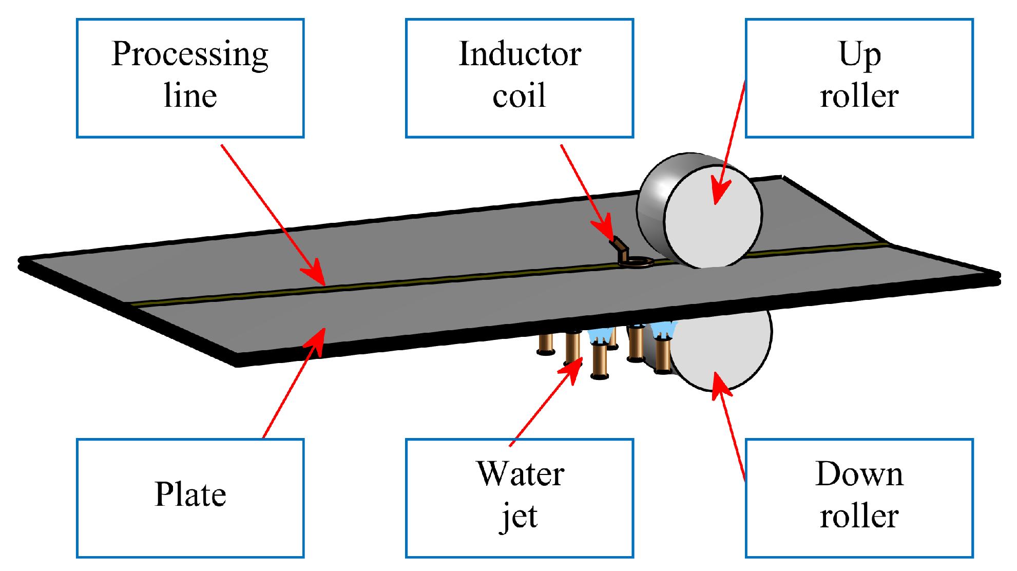
The IHMRF processing consists of convex–concave rollers for cold press bending and an electromagnetic induction coil heat source for line-heating [
11], as shown in
Figure 1. The plate is placed between the rollers, where the rollers perform cold processing and drive it to move via frictional rolling. The electromagnetic induction coil heat source is positioned on the surface of the plate before or after the rollers, providing line-heating processing. Cooling water is sprayed beneath the plate during heat processing. Rolling and heating processing can be used simultaneously or separately; turning off the electromagnetic induction coil enables standalone cold processing, while using the rollers merely to drive the plate through friction achieves standalone line-heating processing. The rollers and the heating by the induction coil are narrow compared to the plate’s dimensions, which can be interpreted as “line” processing.
In the electromagnetic induction line-heating process, the thermal expansion is constrained and squeezed by the surrounding cold plate. Since the yield strength of the material is significantly reduced by the heat, the heat area will go into plasticity, so when the heated plate shrinks in cooling, it will produce greater deformation. Because of the skin effect in induction heating, it will simultaneously produce in-plane shrinkage deformation and bending deformation [
12]. However, due to limitations by the heat source speed and the steel’s austenitization temperature, the resulting bending deformation is generally minor. Effectively producing in-plane shrinkage deformation is the primary advantage of this line-heating method. For the convex–concave roller cold bending process, the plate under compression in the middle of the rollers can be interpreted as forming a localized three-point bending configuration, primarily generating bending deformation in the plate. Combining or integrating these rolling and heating processing tools addresses the input requirements for various deformation components needed in the forming of complex curved plates.
The IHMRF method provides a deformation and strain input that is more suitable for plate forming, while also introducing more complex forming processes. The transformation of the actual three-dimensional continuous strain distribution into a discrete distribution of in-plane and bending strain along a path becomes a key challenge in IHMRF. This is also the primary issue in developing a processing scheme. We refer to this process as developing a strain path map. The strain path map and the processing scheme must not only account for the local deformation and strain but also consider the impact of each forming path on the overall deformation. However, the relationship between the local deformation caused by a single path and the overall deformation is highly complex and must consider geometric nonlinearity, as simple superposition is clearly inappropriate. Moreover, unlike conventional line-heating or press rolling methods that are used in isolation, the relationship between the tools used in IHMRF and the resulting deformation and strain becomes significantly more intricate. Therefore, the strain path map and the processing scheme must be tailored to the characteristics of IHMRF. Further, the processing position and the corresponding forming strain can be determined from the strain path map, which we also refer to as the processing path map.
The processing scheme in IHMRF includes the position of the forming lines, the execution sequence of the processing paths, and the process parameters for each line. These should first be derived based on the strain path map. Process parameters are typically directly linked to the strain. Thus, by analyzing the strain requirements of the target shape to generate a strain path map, and then matching the process parameters, the processing scheme for IHMRF is developed.
Based on the structure of the processing scheme outlined above, this article identifies the following four key issues:
- 1.
Establish the correspondence between the target curved surface shape and the distribution of processing strain, thereby determining the strain distribution based on the target shape;
- 2.
Discretize the strain distribution to obtain strain paths and assign appropriate strain values to form the strain path map;
- 3.
Perform engineering approximations of the strain path map based on the processing equipment and methods to generate a processing path map;
- 4.
Match the processing path map with the process parameters of the corresponding forming tools to construct the processing scheme, followed by validation and correction of the effectiveness of achieving the target shape.
2.2. IHMRF Equipment for Experiments
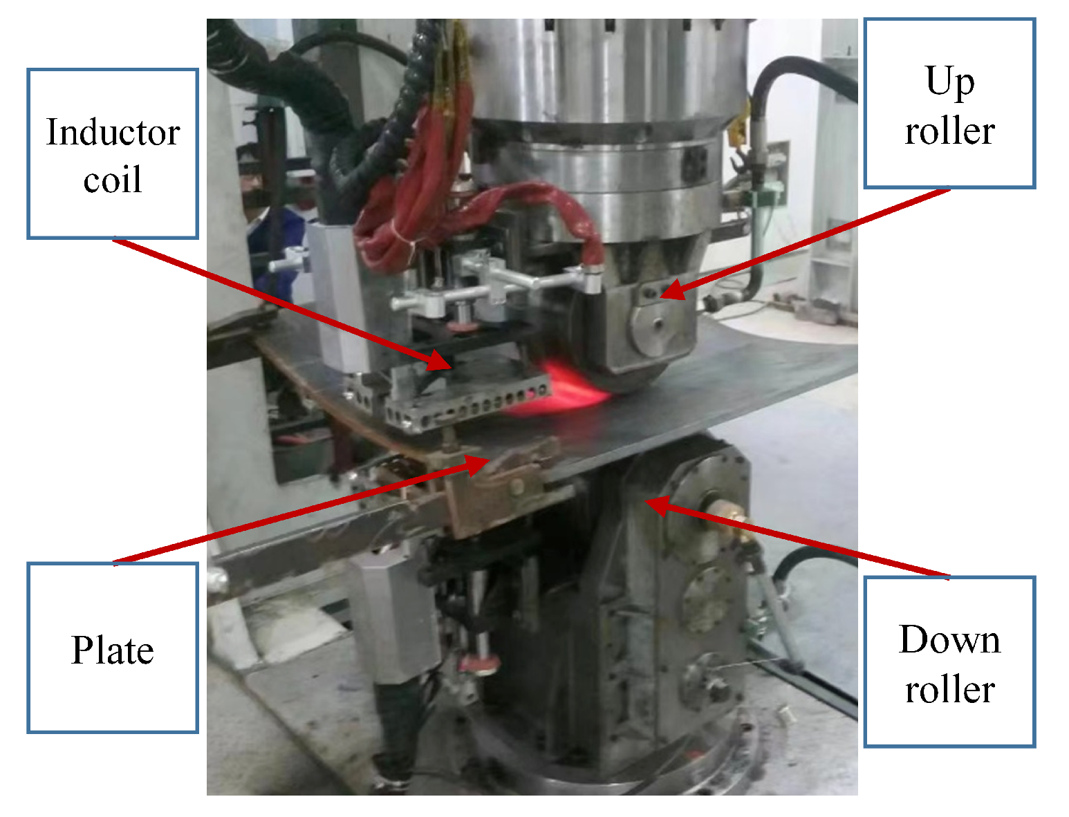
The forming equipment consists of rollers, an induction heating system, a servo positioning system, a laser scanning measurement system, and other auxiliary components, shown in
Figure 2. The roller and the induction heater can be used either together or separately, allowing for individual line-heating, individual press rolling, or IHMRF method. In the rolling system, the upper roller has a width of 200 mm, the lower roller has a width of 300 mm, and the roller curvature radius is 550 mm, with a maximum press force of 50 tons. The induction heating system features a heat source diameter of 100 mm and a maximum output power of 160 kW.
The IHMRF equipment also includes auxiliary components such as the servo positioning system, laser scanning measurement system, and workpiece spray cooling system. The servo positioning system is responsible for controlling the position and motion of the plate, working in tandem with the rollers. It also handles the feeding and unfeeding of plates. The laser scanning measurement system measures the shape of the formed plate and feeds the data back to the control system for shape precision control. The workpiece spray cooling system is used during line-heating processes to cool the plate rapidly, preventing forming deviations caused by excessive heat accumulation.
2.3. Numerical Forming Method for IHMRF
To study the deformation and strain characteristics of IHMRF method, simulations of the forming process can be employed. Finite element simulations were conducted using ABAQUS 2020 software. Firstly, a finite element model of the plate was established with a mesh size of 10 mm. For deformation calculations, four-node reduced integration shell elements (S4R) were used, while four-node heat transfer elements (DS4) were employed for thermal simulations.
In the press rolling process, the convex and concave rollers were set as rigid bodies. Since the rolling speed is typically low, the rolling process is treated as a quasi-static process for simulation. For the line-heating process, the heat transfer is simulated first. The heat source is simplified as a surface heat flux density, avoiding the complexity of simulating thermo-electromagnetic coupling. A DFLUX subroutine in ABAQUS is used to implement the loading and motion of the surface heat source. The thermal boundary conditions included convective and radiative heat loss to the environment. After the heat transfer simulation, the resulting temperature field is applied as a thermal load in the elastoplastic calculation to solve for the deformation caused by the line-heating process.
In the elastoplastic simulation, spring boundary conditions were applied at the four corners of the plate to simulate the support provided by slings in the actual process. Rigid body motion is constrained in the finite element simulation. For IHMRF method, the simulation involved combining the thermal and mechanical processes: first performing heat transfer calculations, then applying the thermal load simultaneously with the roller to simulate deformation.
To validate the finite element simulations and the accuracy of the inherent strain method, simulation results were compared with experimental data. The experiments were conducted using the IHMRF equipment, involving multiple passes. The processing routes are shown below in
Figure 3. Routes 1–7 represent press bending lines with a press depth of 3 mm, while routes 8–9 involve IHMRF method, with a press depth of 3 mm, heating power of 60 kW, and a processing speed of 10 mm/s.
Comparison of finite element simulations with experimental results shows good agreement, as shown in
Figure 4. Both thermoplastic finite element simulations and inherent strain predictions effectively predict the deformation during the forming process. This indicates that the finite element model and the inherent strain method are valid. Thermoplastic finite element simulations provide detailed histories of physical field changes during processing, while the inherent strain method provides fast deformation predictions, both with high accuracy.
3. Proposed Method for Processing Scheme Generation
3.1. Relationship Between the Target Surface and Strain, and Determination of the Strain Path Map
Firstly, analyze the strain characteristics of a complex curved surface. Forming a complex curved plate requires both in-plane strain and bending strain components, and both are indispensable. For the line-loading forming method, creating a strain path map involves determining the strain path distribution and the value of strain input required for forming a plane into a complex curved plate. The strain path map itself includes the positions of the strain input lines, the strain values assigned to each line, and other relevant input conditions.
According to plate theory, forming a plane into a complex curved plate geometrically implies that the strain distribution on the plate changes. The method typically used to determine the strain distribution for a target curved surface is the process of flattening, which is the inverse process of forming. By reversing the sign of the strains obtained during flattening, the required strain values can be derived. The calculated strain values are then separated into in-plane strain and bending strain components, using the following method in Equation (
1) [
12]:
where
denotes in-plane strain and
denotes bending strain. where
is the strain at the
i-th layer and
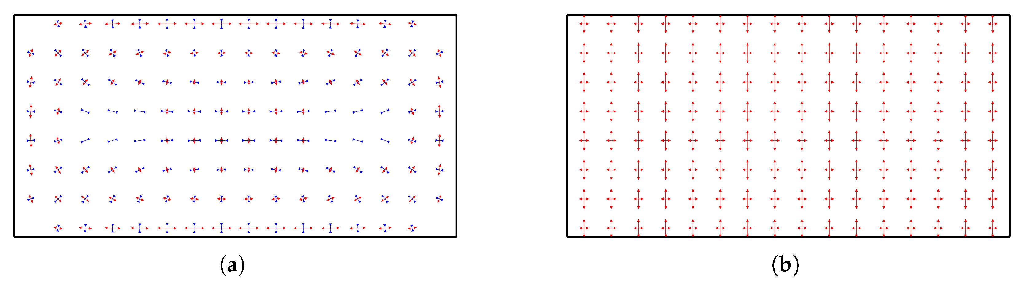
is the corresponding layer thickness. The bending strain is then obtained by subtracting the in-plane component from the total strain at each point. In our implementation, the plate is discretized into 5 layers. Furthermore, each strain component is converted into its principal strain representation. Taking a parametric target curved surface
as an example, the distributions of the in-plane and bending principal strains are shown in
Figure 5.
From
Figure 5b, it is evident that the bending principal strain exhibits a clear linear distribution. These lines closely approximate the principal curvature lines of the curved surface, which aligns with thin plate theory and is consistent with previous considerations of curvature lines determined by bending strain. From
Figure 5a, as previously noted, the in-plane strain shows no significant correlation with the curvature lines.
The IHMRF method belongs to the category of line-loading processing. Regardless of whether the process involves heating or rolling, the principal direction of the strain induced by the processing is typically orthogonal to the processing paths. For bending deformation, the primary bending deformation caused by the processing paths occurs in the direction perpendicular to the processing paths, while bending deformation in the direction parallel to the processing paths is relatively small. Therefore, applying bending strain along the principal curvature directions of the target curved surface enables the main bending strain required to achieve the desired curved surface shape. In other words, it is reasonable to use the principal curvature lines of the curved surface as the strain paths for applying the bending principal strain. This simplifies the determination of processing paths for bending strain.
The strain paths are determined to align with the principal curvature lines of the curved plate. It is also necessary to assign strain values to each line. For shipbuilding curved plates, most of the curved surfaces exhibit smooth and continuous shapes. Therefore, the strain distribution derived from flattening such surfaces is generally continuous. However, the principal curvature lines of the surface obtained are discrete in an engineering context. The strain applied by line-loading processing can also be considered discrete. To ensure the forming accuracy, the strain values on each discrete path must be carefully controlled. Evidently, the strain values will vary depending on the density of the lines.
Correspondingly, the in-plane strain distribution is more complex. In thin plate theory, deformation in the thickness direction is ignored, resulting in a distribution with multi-solution characteristics. This implies that different in-plane strain distribution can still maintain consistency in deflection from the plane to the target curved plate shape. For curved plate forming in shipbuilding, the focus lies on the consistency of shape in the deflection direction of the plate, while minor variations in thickness and edge geometry can be neglected. As mentioned earlier, since bending strain is well-correlated with the curvature lines, to adapt to the characteristics of IHMRF, in-plane strain should also be discretized and concentrated along the curvature lines. This unifies the distribution of both components of strain along the same line.
In summary, the arrangement of the strain path map transforms into solving the curvature lines. Solving curvature lines can be simply described as follows. First, determine the curvature and principal curvature directions at each point on the surface. Then, solve the curvature line equations based on the principal curvature directions to obtain the curvature lines [
13]. To prevent interference between strain paths, an appropriate distance should be maintained. Considering both strain paths and the requirements for IHMRF, the basic characteristics of strain paths can be summarized as follows:
Strain paths are arranged along curvature lines, considering only strain perpendicular to the strain path direction.
A distance should be maintained between strain paths to avoid interference.
Strain paths must cover the entire plate area to ensure the shape requirement.
To ensure that the in-plane strain and bending strain derived from surface flattening share the same principal direction, a new flattening method is proposed. This method is based on mechanical flattening method and employs a virtual modification of the material’s constitutive relationship to alter the in-plane strain distribution. It is important to note that this flattening is a virtual operation intended solely to extract the strain distribution required to generate the target surface, and not to reflect the real material behavior during forming. The adoption of a bimodulus material model serves as a tool to control the direction and magnitude of in-plane strain, ensuring alignment with the principal curvature directions. By constraining the in-plane strain distribution, the in-plane strain can only consist of tensile or compressive strain, and approximating aligning with the principal direction of principle curvature. The key to this flattening method lies in constructing a bimodulus material model [
14]. For bending deformation, an isotropic linear elastic material is used. For in-plane deformation, a bimodulus material model is adopted, where different Young’s moduli are used for the tensile and compressive regions. In the tensile region, the Young’s modulus is
, while in the compressive region, it is
, with
. Under these conditions, the material exhibits easier compressive deformation, while tensile deformation is constrained. This model ensures that the in-plane strain obtained is predominantly compressive. Simultaneously, based on the in-plane displacements
obtained, the positions of the curvature lines on the flattening plane can be determined. The aforementioned mechanical flattening can be completed using numerical methods.
In the numerical implementation of this flattening method, specific boundary conditions and simplifications are introduced to ensure a stable and geometry-driven strain solution. Free boundary conditions are applied around the edges, while rigid body motions are constrained to avoid numerical instability during solving. The flattening process is achieved by prescribing displacements that virtually unfold the surface into a planar configuration, rather than simulating an actual physical deformation process.
In surface flattening, strain is distributed across the entire plate, but actual processing only occurs along the strain paths. Once the strain paths are determined, the strain along these paths is also defined. However, this strain value does not meet the equivalence requirements of a continuous strain distribution, so the relationship between discrete lines, their density, and assigned values needs to be reconsidered. The continuous strain distribution must be discretized onto the strain path map. Based on the flattening results, the strain value at any point p on the strain path can be determined as follows:
- 1.
Locate the central lines
and
between the strain path
and adjacent strain paths; see
Figure 6. If
is at the edge of the plate, one of these lines will be the edge line.
- 2.
Draw a line through point p that is perpendicular to . Let intersect and at points and , respectively.
- 3.
Integrate the in-plane strain and bending strain along : .
- 4.
Assign and as the processing strain values at point p, which can also be referred to as the shrinkage and angular deformation, respectively.
3.2. Determination of the Processing Path Map
Under real engineering conditions, the arrangement of processing paths is subject to constraints of forming tools, necessitating the engineering refinement of discretized processing routes and strain values. For IHMRF, the plate’s movement is controlled by rollers, which limits feasible routes to straight lines. Moreover, the plate must be supported and constrained by the upper and lower rollers, restricting the processing region. The roller edges must not extend beyond the plate’s edges, meaning the processing paths cannot be too close to the plate edges. For complex surfaces, curvature lines as well as the strain paths are typically curves. And the strain distribution along these processing paths usually varies continuously. However, continuously controlling strain is often challenging. Therefore, the engineering refinement of processing routes and strain values includes: (1) Approximating curved strain paths with piecewise segments; (2) Continuously approximating strain distributions with segmented values.
For parametric surfaces, strain paths may naturally be straight lines. However, curved processing paths are often impractical in engineering. Thus, approximating curved strain paths with equivalent polyline segments is a practical solution. This process can be described as follows: For a strain path
, find a polyline
such that the maximum distance between
and
is less than a specified tolerance
:
; see
Figure 7. An approximate method is detailed as follows. For IHMRF, polyline routes are more feasible to implement. By the following steps, we obtain engineered polyline processing routes. Furthermore, by controlling the maximum deviation
, equivalence between polyline routes and curved paths can be achieved.
- 1.
Take the start and end points of the strain path , denoted as and , as the start and end points of the polyline ;
- 2.
Compute ;
- 3.
If , insert the point , located at the position of maximum distance, into , thereby increasing the number of polyline segments and forming a new ;
- (4)
Repeat steps 2 and 3 until the condition is satisfied;
- (5)
Calculate (signed), representing the positional relationship between the curve and the polyline ;
- (6)
Offset the polyline by a distance equal to , so that the curve is distributed on both sides of the polyline , approximately satisfying the condition .
A comparative evaluation under various forming conditions (including rolling, heating, and IHMRF) showed that a tolerance value around 50 mm offers a good balance between path simplification and shape accuracy. Within this range, the deviation in the final formed geometry remains below 5%, which meets practical forming requirements. Therefore, mm is recommended as a default setting.
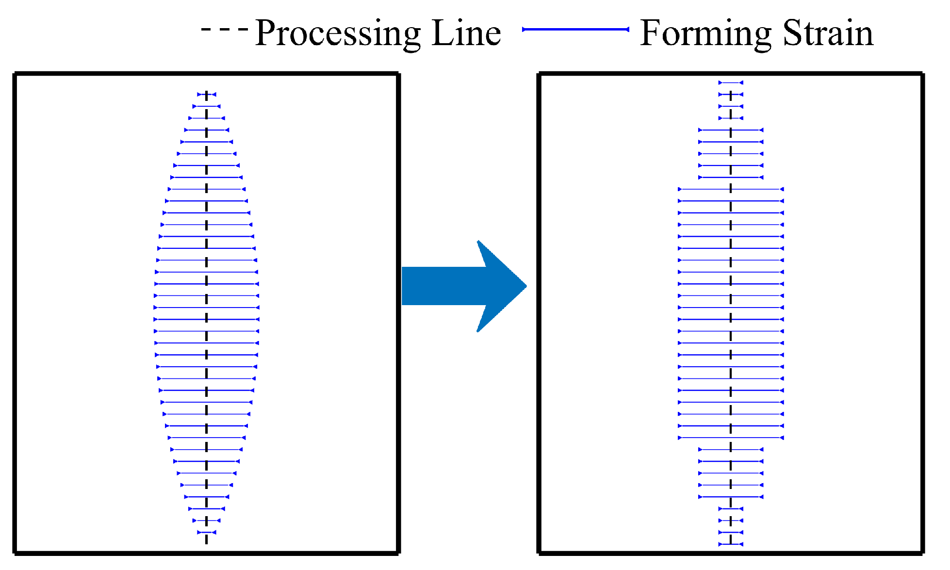
The strain values along processing paths are usually continuous. For ease of processing path, the continuous strain values need to be approximated in piecewise form, as shown in
Figure 8. The equivalence from continuous strain values to piecewise approximated strain values should meet the following principles:
- 1.
Each segment must not be too short. Frequent switching of processing parameters may lead to inaccurate strain and reduced processing efficiency. Therefore, the length of each segment must be greater than a minimum processing length.
- 2.
Based on the first principle, the deviation between the continuous strain values and the approximated strain values in each segment must not exceed a certain range. When the strain deviation is too large, the approximated strain values cannot accurately approach the target strain, leading to lower processing accuracy. Therefore, minimal strain deviation should be used to ensure processing accuracy.
The two principles are contradictory; when the segment length increases, the strain deviation is bound to increase, which in turn reduces the machining accuracy. Conversely, when the required strain value deviation is small, a smaller segment length must be used, and too short a processing path may lead to inaccurate strain and less efficiency. Therefore, it is necessary to make a trade-off between the two, and here we give priority to principle 1, avoiding the use of too short processing paths as much as possible.
To achieve a balance between accuracy and feasibility, the strain discretization is formulated as a constrained optimization problem. Specifically, the continuous strain function
is approximated using a piecewise constant function
:
The objective is to minimize the squared deviation between the original and approximated strain distributions, defined by:
Here, is a weighting function that can be adapted to emphasize regions with large strain gradients or magnitudes. This prevents over-smoothing and ensures high-fidelity reproduction of critical deformation areas.
To ensure manufacturability, the segment length must satisfy:
where
is the minimum processable length determined by equipment limitations. Moreover, the number of segments
n is determined iteratively to ensure that the relative strain deviation remains within an acceptable tolerance:
This approach ensures that the generated processing route is both geometrically accurate and operationally feasible, while also enabling flexible adjustment of discretization granularity depending on forming complexity.
3.3. Matching Process Parameters and Validating the Processing Scheme
After obtaining the processing path, the positions of the processing paths and the strain to be applied along these paths were determined. Next, it is necessary to establish the process parameters corresponding to the required strain. For IHMRF method, the main process parameters include processing speed, heating temperature, and roller press depth. Based on the previous discussion of processing tools, the deformation characteristics corresponding to the process parameters can be described using transverse and longitudinal in-plane strain, bending strain. These four strain parameters can be treated as a four-dimensional space , where . A set of process parameters uniquely corresponds to a set of strain values , in other words, a point in . Based on the processing tool’s capacity, all feasible process parameter combinations form a set Q, which can be mapped to a region in , such that . The region represents all achievable strains. For strain on each processing path, by focusing on the dominant transverse strain, it can be represented as . Therefore, the problem of matching process parameters can be described as finding a point in Q that can best achieve . This can be outlined as follows: Using the above steps, the processing times and process parameters for each path can be obtained. This transforms the ideal strain required by the processing path into the achievable strain .
- 1.
For each processing path, evaluate whether the required strain can be achieved. If it exceeds the maximum capacity of the process, divide the processing into n steps such that the strain per step satisfies .
- 2.
Find the closest achievable strain: In , identify the strain that is closest to (or ) using a weighted Euclidean distance: where are weights that can be adjusted based on the processing tool. For IHMRF method, the primary strain is the transverse strain perpendicular to the processing path, so the weights can be set as .
- 3.
Determine process parameters: Using , determine the corresponding process parameters q.
It should be noted that, in the strain-matching algorithm, the weighting factors are assigned based on the characteristics of the IHMRF process. Since the deformation is mainly concentrated in the transverse direction, a larger weight is given to the transverse strain component. The longitudinal strain has less influence on the overall shape and is therefore assigned a smaller weight. The current weights are mainly selected based on empirical knowledge of the process.
Next the processing scheme needs to be validated. Rapid deformation prediction can be achieved using the inherent strain method [
12]. The inherent strain method treats the plastic strain as the inherent strain, applying it as a load to the plate for deformation prediction. This method simplifies the processing as an elastic calculation, significantly reducing computation. In multi-pass IHMRF forming, the inherent strain method assumes that each processing path generates a stable and repeatable strain. To minimize thermal accumulation between successive passes, water cooling is typically applied in practice, which helps maintain consistent processing conditions. Material hardening and residual stresses may influence the strain distribution, particularly at intersections of processing paths. Applying certain correction methods can improve the prediction accuracy of the forming results.
In finite element analysis, the equilibrium equation can be expressed as in Equation (
6) [
15]:
where
is the stiffness matrix,
is the nodal displacement matrix, and
is the nodal force matrix. For the inherent strain method, the nodal force matrix
can be calculated as in Equation (
7):
where
is the strain–displacement matrix,
is the material stiffness matrix, and
is the inherent strain. This relationship allows the inherent strain applied to each element to be converted into nodal forces, enabling the calculation of nodal displacements and the final shape of the processed plate.
In this process, discrepancies between the applied strain and the target strain may arise after discretizing and engineering the strain from the surface. Hence, iterative reverse-deformation corrections are required to ensure that the processed plate’s actual shape closely matches the target shape. The iterative reverse-deformation correction can be described as follows. Through this process, the relationship between the target processing shape, processing paths, and processing strain is established:
- 1.
Apply the processing strain to the plate using the inherent strain method to predict the processed shape .
- 2.
Calculate the deviation between the predicted shape and the target shape .
- 3.
If the deviation satisfies the accuracy, the final processing strain is determined. Otherwise, add the deviation to the original target shape to obtain a new target shape: and regenerate the processing strain based on the new target shape.
- 4.
Repeat the above steps until the deviation satisfies the accuracy or no further reduction in deviation.
5. Conclusions
This paper proposes a method for generating processing routes for curved plate forming using IHMRF method. The method involves deriving the strain distribution from surface flattening calculations, discretizing the continuous strain distribution into individual processing routes, and refining it into practical engineering processing scheme. The main conclusions are as follows:
- 1.
The proposed method establishes a quantitative relationship between the target surface geometry, the processing route, and the required strain distribution. It provides a standardized procedure for generating processing routes and strains, laying a solid foundation for the automation of hull plate forming.
- 2.
The method demonstrates good generality and adaptability across different curved surface types. Forming experiments on representative curved surfaces show that the generated schemes achieve the target geometry with a deviation within 5 mm, proving the method’s capability in guiding practical forming processes.
The proposed method has primarily been validated on standard ship hull surfaces, which are generally smooth and moderately curved. Its performance on highly complex or free-form surfaces remains unverified. Such geometries typically exhibit more complex and non-uniform strain distributions, which complicates the discretization of strain paths and their translation into feasible engineering processing schemes. This increased complexity may lead to larger shape deviations during the forming process, potentially affecting the accuracy and reliability of the final formed plates. In addition, the current approach heavily depends on finite element analysis for both strain calculation and processing scheme validation. This reliance on finite element analysis significantly increases computational costs, particularly for large surfaces, which may limit the method’s scalability and suitability for batch or real-time industrial applications.
Future research will aim to enhance the accuracy of the processing schemes by introducing deviation correction mechanisms during or after forming. In parallel, optimization of each module within the processing workflow will be pursued, with a focus on improving computational efficiency and adaptability to various production scenarios. Efforts will also be made to expand the method’s applicability to more complex and non-standard geometries, covering more ship hull surfaces. Ultimately, these developments are expected to support the integration of the method into intelligent and automated shipyard environments, enabling more flexible, accurate, and efficient curved plate forming processes.


