Article

Investigation of Implantable Capsule Grouting Technology and Its Bearing Characteristics in Soft Soil Areas

1
Collaborative Innovation Center of Coastal Urban Rail Transit, Ningbo University, Ningbo 315211, China
2
Ningbo Key Laboratory of Energy Geostructure, Ningbo University, Ningbo 315211, China
3
Ningbo Zhongchun Hi-Tech Co., Ltd., Ningbo 315145, China
*
Author to whom correspondence should be addressed.
J. Mar. Sci. Eng. 2025, 13(7), 1362; https://doi.org/10.3390/jmse13071362
Submission received: 3 June 2025 / Revised: 18 June 2025 / Accepted: 15 July 2025 / Published: 17 July 2025
(This article belongs to the Section Coastal Engineering)

Abstract

The implantable capsule grouting pile is a novel pile foundation technology in which a capsule is affixed to the side of the implanted pile to facilitate grouting and achieve extrusion-based reinforcement. This technique is designed to improve the bearing capacity of implanted piles in coastal areas with deep, soft soil. This study conducted model tests involving multiple grouting positions across different foundation types to refine the construction process and validate the enhancement of bearing capacity. Systematic measurements and quantitative analyses were performed to evaluate the earth pressure distribution around the pile, the resistance characteristics of the pile end, the evolution of side friction resistance, and the overall bearing performance. Special attention was given to variations in the lateral friction resistance adjustment coefficient under different working conditions. Furthermore, an actual case analysis was conducted based on typical soft soil geological conditions. The results indicated that the post-grouting process formed a dense soil ring through the expansion and extrusion of the capsule, resulting in increased soil strength around the pile due to increased lateral earth pressure. Compared to conventional piles, the grouted piles exhibited a synergistic improvement characterized by reduced pile end resistance, enhanced side friction resistance, and improved overall bearing capacity. The ultimate bearing capacity of model piles at different grouting depths across different foundation types increased by 6.8–22.3% compared with that of ordinary piles. In silty clay and clayey silt foundations, the adjustment coefficient ηs of lateral friction resistance of post-grouting piles ranged from 1.097 to 1.318 and increased with grouting depth. The findings contribute to the development of green pile foundation technology in coastal areas.

1. Introduction

The marine economy has developed rapidly worldwide, accompanied by continued growth in coastal engineering construction. Pile foundations are the most commonly used foundation type in coastal areas and play a crucial role as an essential component of coastal engineering. However, the geological conditions in coastal areas are complex. Deep, soft soils with high water content and environmental protection requirements pose significant challenges to pile foundation construction. Implanted pile technology is an emerging green pile foundation technology that has been widely adopted in coastal areas across many countries [1]. This technology effectively addresses the problems of vibration, noise, and soil displacement associated with traditional prefabricated piles by incorporating pre-drilling, grouting, and implanting high-strength prestressed pipe piles. It offers significant advantages, including reduced greenhouse gas emissions and a lower carbon footprint, as well as reduced mud discharge [2].
Many studies have investigated the load-bearing capacity and environmental benefits of implanted piles. Gong et al. [3] developed a theoretical model to estimate the ultimate bearing capacity of implanted piles and analyzed their load-bearing capacities. Yu et al. [4] observed that implanted piles outperform hammer-driven or statically pressed piles in penetrating hard strata. The composite pile body structure, formed by prefabricated pipe piles and surrounding solidified grout, can enhance the load-bearing capacity and deformation resistance of the piles. Zhou et al. [5] reported that on-site monitoring revealed slight disturbances to the surrounding soil during the construction process of implanted piles. However, the horizontal earth pressure, super-static pore water pressure, and horizontal displacement of the deep soil in the surrounding soil recovered rapidly after the construction was completed. The influence range of this construction disturbance was within a 4D radius (D represents the pile diameter). Zhou et al. [4] found that under the same geological conditions, implanted piles used only 35.7% of the concrete and discharged 36.2% of the slurry compared with cast-in-place piles. This proves that this technology is resource-efficient and environmentally friendly.
Engineering practice in coastal deep soft soil areas has found that the lateral resistance provided by soft soil on pile sides is relatively low, resulting in limited bearing performance of implanted piles. Therefore, enhancing the bearing capacity of these piles and improving foundation stability remain urgent challenges. Ling et al. [6] proposed increasing the borehole diameter to improve the bearing capacity of the pile foundation; however, this approach significantly raises construction costs. Zhou et al. [7] proposed increasing the cement content to improve bearing capacity and experimentally investigated how factors, including side cement content and cement strength, affect the bearing performance of implanted piles. Zhou et al. [8] further investigated the impact of cement–soil additives on pile bearing capacity, finding that the addition of additives such as slag and gypsum significantly enhanced performance, with an increase in bearing capacity corresponding to the increase in additive content. Yu et al. [9] investigated the time-dependent behavior of lateral friction resistance at the interface between pipe piles and cement–soil and found that the bearing capacity of the implanted piles increased continuously over one month. Deng et al. [10] proposed enhancing pile capacity by incorporating drainage channels into the cement–soil around the pile and applying vacuum pumping. Large-scale model tests revealed that longer pumping and drainage durations resulted in reduced water content in the surrounding cement–soil, thereby improving the pile’s bearing capacity.
Post-grouting technology is also an important method for enhancing the bearing capacity of pile foundations. It was initially applied to bored cast-in-place piles, primarily by injecting grout at the pile ends or along the pile sides to increase capacity [11]. Wan et al. [12] analyzed the results of horizontal static load tests and observed that the horizontal critical load of post-grouting pile foundations was 25% higher than that of ordinary piles, and the ultimate bearing capacity increased by 14.3%. Salem et al. [13] employed numerical analysis to demonstrate that post-grouting can enhance the mechanical properties of the surrounding soil and improve the vertical bearing capacity of the pile. Zhang et al. [14] demonstrated through indoor model tests that side and rear grouting of piles can control pile settlement and reduce the relative displacement between piles and soil. Wan et al. [15] demonstrated through model tests that rear-side grouting can approximately double the horizontal bearing capacity of pile foundations. Wang et al. [16] found from on-site tests that the total uplift bearing capacity of post-grouting piles was approximately 45% higher than that of ordinary piles. Additionally, post-grouting piles can reduce the amount of concrete used. A challenge in selecting cast-in-place pile technology is the environmental problem caused by mud discharge. In contrast, prestressed pipe piles can eliminate or significantly reduce the need for mud discharge. Consequently, researchers have begun exploring the integration of post-grouting with prestressed pipe piles. Hu et al. [17] demonstrated through field testing that side and rear grouting can increase the vertical compressive bearing capacity of pipe piles, and the increase exceeds the code-recommended values for cast-in-place piles. Gao et al. [18] concluded from case analyses that post-grouting of prestressed pipe piles can eliminate the adverse effects of floating piles and improve bearing capacity. MINTAEK et al. [19] confirmed through static load tests that post-grouting can increase the bearing capacity of pipe piles. The bearing capacity of post-grouting piles was approximately three times higher than that of non-post-grouting piles, while the axial stiffness increased by 1.3 times. Karimi et al. [20] found that post-grouting can enhance soil–pile interaction and densify the soil around piles, thereby improving the bearing capacity of prefabricated piles. However, post-grouting technology for prestressed pipe piles still has several limitations, including a complex grouting process, challenges in quality control, increased construction costs, and variability in grouting effectiveness, which restrict its broader application.
In response to the above technical bottlenecks, we proposed an innovative implantable capsule grouting pile (ICGP) technology. This technology leverages the construction advantages of implanted piles. The prefabricated pipe piles with bound capsules are implanted into cement soil pile holes. High-pressure injection of cement slurry into the capsules compacts the surrounding soil around and increases the contact area between the piles and the soil, thereby improving the load-bearing performance. The critical factors affecting the compaction effectiveness of high-pressure capsule bag grouting on surrounding soil include: the tensile strength and permeability of the capsule bag material, grouting pressure and injection rate, the water–cement ratio and consolidation characteristics of the grout, the permeability coefficient and stratification differences of the soil, the burial depth and expansion constraints of the capsule bag, as well as the disturbance of groundwater dynamics on grout diffusion. This study conducted a series of model tests to assess the stress and deformation characteristics of the pile–soil system, refining the construction process and investigating the bearing mechanism. The side friction resistance enhancement coefficient and the overall bearing capacity of the piles were comparatively analyzed. The results were further applied to engineering case studies to examine practical considerations for field implementation. The findings contribute to the development of green, high-performance pile foundation technologies in coastal areas.

2. ICGP

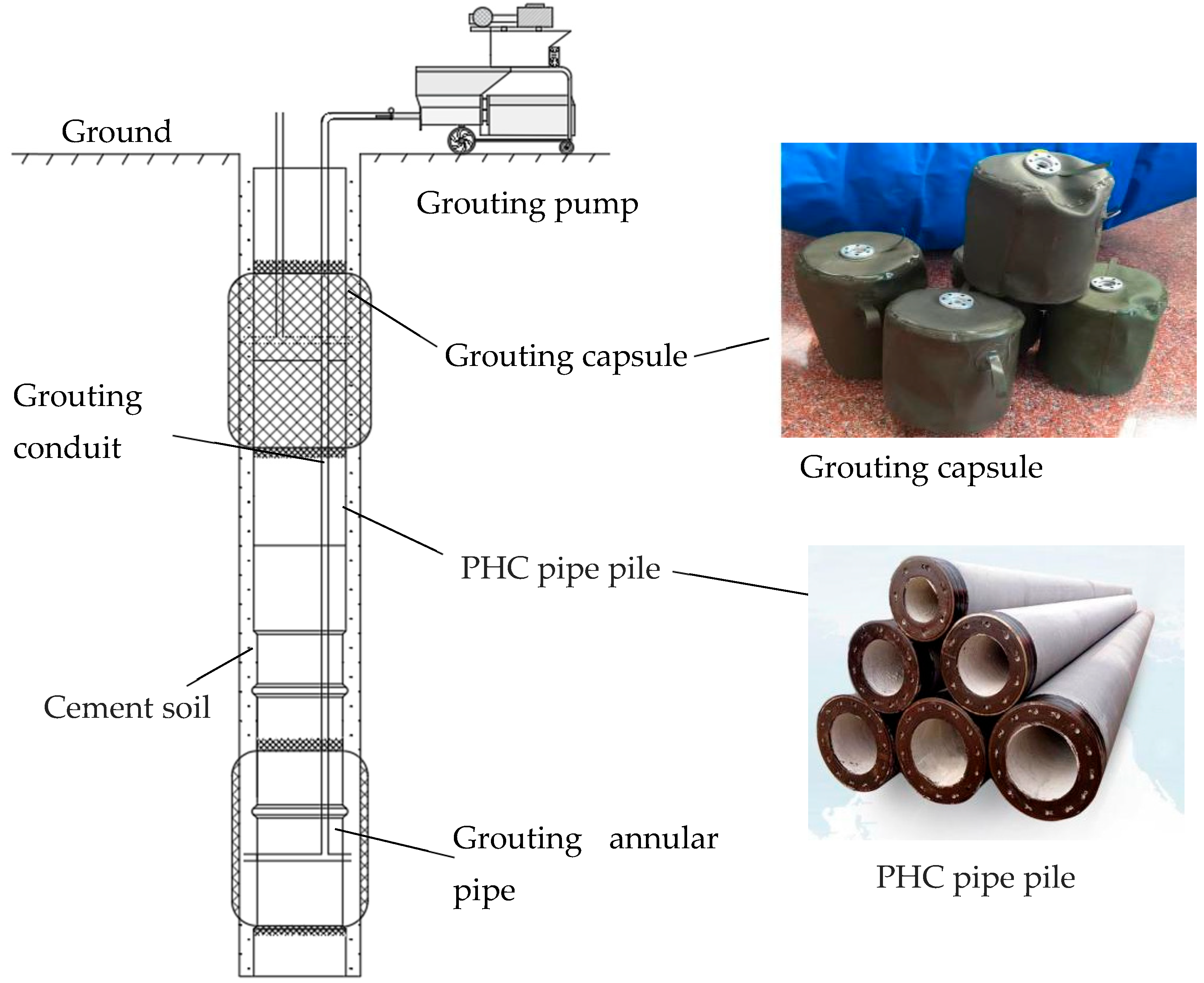
2.1. Principle of Technical Composition

The ICGP technology is an innovative pile foundation technology developed based on implantable piles, specifically designed for deep, soft soil conditions in coastal areas. This technology fully leverages the construction advantages of the implanted piles, including pre-drilling, cement slurry injection to form a cement soil, and subsequent implantation of high-strength prestressed pipe piles before the cement soil sets. They have the advantages of minimal vibration and soil displacement, reduced slurry discharge, and high structural strength. Since the pile holes are pre-formed and larger than the pile diameters, the implantation process generates low resistance, allowing for the smooth installation of prefabricated piles with side-bound capsules into the holes.
The structure of ICGP is illustrated in Figure 1. The components of this technology include prefabricated pipe piles, grouting capsules, and a grouting system. Prefabricated pipe piles are often made of high-strength prestressed concrete, with a recommended diameter ranging from 0.3 to 0.5 m. The grouting capsule, a flexible structure designed to contain the grouting materials, is fixed to the pile body using binding straps. The grouting system includes a grouting pump and conduit. The grouting pump serves as the power source for the grouting system, and the grouting material is injected into the capsule through the grouting conduit.

2.2. Grouting Capsule

The capsule is made of natural rubber cloth, primarily composed of natural latex and manufactured through processes such as vulcanization. It features high strength, high resilience, and tear resistance, and is environmentally friendly and non-toxic. During construction, the rubber cloth is cut into appropriately sized rectangles and wrapped around the perimeter of the pile. The upper and lower ends are then narrowed and secured with binding straps. Due to its adhesiveness, natural rubber offers good airtightness, preventing the leakage of grouting materials and ensuring a satisfactory grouting effect. It also exhibits strong low-temperature resistance, allowing for its use during winter construction. It is lightweight, easy to install, and cost-effective. The material properties included density (ρ), tensile strength (σt), elongation at break (εb), tear resistance (Tr), hardness (Ha), temperature (T), acid resistance (Ar), and alkali resistance (Alr). The material properties are presented in Table 1.

2.3. Grouting System

The grouting system of ICGP includes grouting conduits and pumps. The grouting conduit consists of stainless-steel pipe, which is corrosion-resistant, has high compressive strength, and is suitable for long-term underground environments. The diameter of the grouting conduit is slightly larger than that of the grouting pipe connected to the grouting pump. The grouting conduit is connected by a flange or high-pressure thread, which reduces pressure loss and enhances its sealing performance. The grouting equipment uses a medium-pressure screw grouting pump fitted with a grouting pressure monitoring sensor, capable of operating within a pressure range of 3–10 MPa and delivering a flow rate of 50–200 L/min. The grouting pump is equipped with a pressure-stabilizing feature to prevent pressure fluctuations from causing capsule rupture or uneven grouting. Additionally, it is equipped with a filtering device to avoid impurities from blocking the grouting pipe or the pores of the capsule.

2.4. Construction Steps

Regarding construction techniques, ICGP technology follows the construction sequence of “hole formation, plant implantation, and grouting.” Initially, boreholes are drilled with a diameter 150–200 mm larger than that of the piles. As the drilling rig is withdrawn, a cement slurry is injected and stirred to form holes for cement–soil piles. Subsequently, prefabricated pipe piles with the grouting capsules bound and the grouting conduits are implanted as a whole into the cement soil pile holes. After the cement soil on the side of the implanted pile sets, grouting begins. The first step of grouting involves conducting a water pressure test on the grouting system using a grouting pump to clear any obstructions in the grouting conduit. Subsequently, the grouting valve is opened, and the grouting material is injected through the grouting conduit into the capsule, thereby forming an expanded bulb around the prefabricated pipe pile. Eventually, the prefabricated pipe pile, grouting material, and capsule solidify into an integrated load-bearing structure. Notably, the waste cement–soil slurry generated during pile installation can be collected using specialized equipment and repurposed as grouting material to be injected into grouting capsules. This addresses the issue of environmental pollution caused by waste slurry and significantly reduces construction costs, thereby supporting the concept of green and environmentally friendly construction.
ICGP technology offers several technical advantages. First, the formation of an expanded bulb structure increases the contact area between the pile and the surrounding soil, uniformly compacting the soil and thereby enhancing the lateral resistance coefficient. This leads to improved lateral frictional resistance, uplift resistance, and overall bearing capacity of the pile foundation, as well as reduced overall settlement. Second, it can effectively solidify the mud skin on the pile side and improve the effect of the mud skin on the pile side. Third, under the same bearing capacity requirements, ICGP allows for reductions in pile diameter and length, offering certain economic benefits. Fourth, it retains the advantages of implantable pile technology, such as low pile driving resistance and ease of construction. Additionally, the capsule system enables efficient side grouting, thereby ensuring effective grout diffusion and close bonding with the pile body. This technology integrates the strengths of implantable piles and post-grouting technology. It retains the advantages of easy construction and minimal environmental impact associated with implantable piles while addressing the limitations of traditional post-grouting technology in terms of grouting effectiveness and applicability on the pile side. This is achieved using an innovative capsule-type grouting system, providing an efficient, environmentally friendly, and economical solution for pile foundation engineering.

3. Model Test

3.1. Test Scheme

To systematically investigate the bearing characteristics of ICGP technology and its applicability under different geological conditions, a comparative test scheme was designed in this study. The test set up two typical stratum conditions in the coastal area: Condition 1 was the silty clay foundation, and Condition 2 was the clayey silt foundation. Four different model pile configurations were set under each working condition. The rear grouting pile featured an innovative design: a grouting conduit was installed on the pile side as the conveying channel for the rear grouting liquid, and a capsule was attached to the pile body as the grout reservoir. The schematic diagram of the model test is illustrated in Figure 2. The model test scheme is shown in Table 2. Four types of model piles were designed for the experiment. Piles P1 and P5 were ordinary implanted piles, consisting of solid precast concrete piles in the middle and surrounded by cement soil. Piles P2 and P6 were ICGPs with grouting at a depth of 10 cm. The model piles P3 and P7 were ICGPs with grouting at a depth of 35 cm. The model piles P4 and P8 were ICGPs with grouting at a depth of 70 cm.
The test equipment included model boxes, monitoring instruments, construction equipment, and static load devices. The model box measured 2.0 m in length, 1.2 m in width, and 1.2 m in height. The monitoring instruments included a data acquisition system, a micro earth pressure sensor (with a range of 300 kPa and an accuracy of 0.1 kPa), an earth pressure gauge, and strain gauges. The construction equipment included grouting conduits, grouting capsules, drilling machines, air compressors, and grouting pumps. Static load devices included reaction frames, jacks, weights, and dial indicators.

3.2. Test Process

3.2.1. Preparation of Model Foundation and Piles

The model test was conducted in a model box measuring 2 m in length, 1.2 m in width, and 1.2 m in height. The foundation soil of the model was collected from silty clay at a foundation pit project in a coastal area of China. Foundation soil preparation followed a layered filling method: After retrieval from the laboratory, the soil was filled into the model box in three stages. Following each stage, a preliminary pre-compaction was performed for 2 h before filling the next layer. The final thickness of the foundation soil layer of the final model was 1.1 m. After completing the filling process, a pressure of 5 kPa was applied for reverse compression using jacks and reaction frames, and the pre-compression time was three days.
After the soil preloading of the model foundation was completed, soil samples were collected from the model foundation, and basic physical and mechanical properties were determined. Geotechnical tests were conducted following the “Standard for Geotechnical Test Methods” (GB/T50123-2019) [21], and the test contents included moisture content w, specific gravity γ, pore ratio e, liquid limit wL, plastic limit wP, cohesion c, and internal friction angle φ. The test results are presented in Table 3.
According to the “Technical Code for Static Drilling Rooted Piles” (T/CECS 738-2020) [22], scaled model piles were used (Figure 3). Each model pile was 0.8 m in length and 110 mm in diameter. After fabrication, the piles were cured in a standard curing room for 28 days. After curing was completed, grouting conduits were installed on one side of the piles. Grouting capsules were affixed above and below the grouting positions using cable ties, and the upper and lower openings were sealed with waterproof tape.

3.2.2. Sensor Layout

The sensor device of the pile–soil system included earth pressure gauges and strain gauges. Earth pressure gauges were used to measure the earth pressure and the pressure at the pile tip, while strain gauges were used to record the strain of the pile body. The data were used to calculate the axial force transmission and lateral friction resistance.
After completing the pre-compaction of the foundation soil, micro earth pressure gauges were installed at specific locations (Table 1).
Seven strain gauges were arranged along each model pile body. Each strain gauge had a resistance value of R = 120.1 ± 0.1 Ω and a sensitivity coefficient of K = 2.20% ± 1%. Before arranging the strain gauges, the pile body was cleaned with medical alcohol. The strain gauges were then attached to the pile body using 502 glue. Each strain gauge was connected to a three-wire shielded cable and wrapped with waterproof tape for protection. The output signals from the measurement circuit were collected by a DH3818Y static strain tester and transmitted to the computer software (DHDAS3818 Dynamic Signal Acquisition and Analysis System) for recording.
An earth pressure gauge was installed at the model pile tip to measure earth pressure changes during the static load test. The installation process involved placing the pressure gauge on the floor, applying special glue, and bonding it to the model pile. The sensor connection wire was then fastened to the pile body using waterproof tape. The entire assembly was embedded into the model foundation. Finally, the earth pressure gauge was connected to a JC automatic acquisition instrument, and data were recorded through the cloud platform.

3.2.3. Construction of Model Piles

The construction process was as follows: First, a polyvinyl chloride pipe with a diameter of 150 mm and a height of 3 cm was inserted into the model foundation for pile foundation positioning. A drilling rig was used to drill the hole, with a small amount of water injected during the process to simulate real engineering conditions. The cement slurry was prepared at a water–cement ratio of 1:1, using ordinary Portland cement with a strength grade of 32.5 MPa. After thorough mixing in a mixing bucket, the cement slurry was injected into the hole through a hollow drill bit. During grouting, the drill bit was lifted synchronously at a uniform speed. Grouting was paused at one-quarter of the designed depth. The drilling rig was stirred for 30 s, and the grouting–lifting–stirring process was repeated until the drill bit was completely pulled out. This ensured uniform grout diffusion and thorough mixing with the soil. The model pile was then vertically centered into the hole and driven in using its self-weight. Once the cement soil began to set, another cement slurry was prepared in the grouting bucket. The slurry outlet pipe was connected to the grouting pipe on the pile side, the air compressor and grouting pump were started, and the pressure gauge at the slurry outlet was monitored. When the pressure reached 400 kPa (a reduced pressure value based on the actual project conditions), the slurry outlet valve was opened to perform post-grouting (Figure 4).

3.2.4. Comparative Detection of Pile Bearing Capacity

In this test, a jack was used to apply the reaction force, and a dial indicator was selected to monitor settlement at the pile top. The static load test was conducted in incremental steps, with each load step set at one-tenth of the estimated ultimate bearing capacity. Before the test, a pre-test determined the ultimate bearing capacity of a single pile to be approximately 5000 N. Accordingly, the load at each step was set to 500 N, and the load was applied progressively until the ultimate state was reached.
The installation of the test equipment is illustrated in Figure 5. After installation, a reaction frame was set up on top of the model box, jacks were mounted on top of the test piles, and displacement measurement devices were symmetrically arranged around the piles. The loading system utilized a combined lever-weight device. After each load increment and after stabilizing the pressure, the pressure data were recorded. After a comprehensive inspection and confirmation of the system’s reliability, the static load test was officially launched. The automatic data acquisition system recorded signals from the earth pressure sensor at the pile tip and strain gauges on the pile body synchronously, while settlement at the pile top was manually observed and recorded.
After the test was completed, the reaction device was removed, and the model piles and the embedded sensors were dug out. The shape of the piles was inspected (Figure 6). The capsule attached to the pile body was swollen. Tests have confirmed that under the same grouting pressure conditions, capsule expansion is more effective in silty clay foundations. Additionally, the expansion effect of the capsule depends on the grouting pressure and the properties of the capsule material. If the grouting pressure is extremely low, the expansion effect of the capsule is not good; if it is extremely high, it may cause the capsule to rupture. Accordingly, determining an appropriate grouting pressure is essential. High elastic modulus capsules have strong resistance to rupture; however, they require a relatively large grouting pressure to expand. Materials with low elastic modulus are prone to expansion but may exceed the limit and break. Consequently, choosing the appropriate capsule material is a critical aspect of the test. Future work can focus on optimizing grouting pressure and improving capsule materials to enhance expansion without causing damage.

4. Analysis of Test Results

4.1. Soil Pressure Around the Piles

The test data obtained from the micro earth pressure gauge around the piles reflected the dynamic changes in earth pressure around the piles during pile construction. The results are presented in Figure 7 and Figure 8. In the silty clay foundation, the staged drilling and grouting during the construction of the implanted piles caused minimal soil disturbance, resulting in a gradual and small increase in earth pressure. During pile installation, the displacement of the cement–soil mixture and surrounding soil led to earth pressure increases of approximately 1, 1.5, and 2.5 kPa at depths of 10, 35, and 70 cm, respectively, indicating a greater increase in earth pressure with depth. During post-grouting, earth pressure around the piles increased significantly by approximately 2, 2.6, and 3 kPa at depths of 10, 35, and 70 cm, respectively. This indicates that post-grouting exerts significant compression on the soil around piles, and the greater the depth, the more pronounced the compression effect. While the same trend was observed in clayey silt foundations, the pile installation and post-grouting processes resulted in less soil compression compared with that in silty clay foundations, indicating that post-grouting on the pile side has a greater impact on silty clay foundations.

4.2. Pile Bearing Capacity

According to the specification, the ultimate bearing capacity of a single pile is defined as the bearing capacity corresponding to a settlement reaching one-tenth of the pile diameter. Therefore, the top load Q corresponding to a top settlement S = 11 mm was taken as the ultimate bearing capacity of the pile. The Q-s curve of the model pile is shown in Figure 9.The ultimate bearing capacity of P1 was 3933.27 N. For P2, it increased to 4199.16 N, which is 1.067 times that of the ordinary pile P1. Pile P3 exhibited a capacity of 4361.58 N, which is 1.1089 times that of the ordinary pile P1. Pile P4 exhibited a capacity of 4739.18 N, which is 1.2049 times that of the ordinary pile P1. Pile P5 exhibited a capacity of 4012.31 N. The ultimate bearing capacity of P6 was 4395.6 N, which is 1.095 times that of the ordinary P5 pile. The capacity of P7 was 4627.46 N, which is 1.153 times that of the ordinary P5 pile, and that of P8 was 4908.2 N, which is 1.223 times that of the ordinary P5 pile.

4.3. Pile Shaft Axial Force

The axial force of the pile body was calculated based on the measured strain of the pile body using the following formula:
N i j = ε i j E A
where Nij represents the axial force of the pile body in the j-th section of the i-level load; εij denotes the strain of the pile body in section j of the i-level load; E represents the elastic modulus of the pile body (taken as 30 MPa); and A represents the cross-sectional area of the pile.
Taking Condition 1 as an example, the calculated variation in axial force along the pile body is presented in Figure 10. As the depth increased, the axial force along the pile body gradually decreased. The axial force along the post-grouting pile body was significantly reduced at the capsule position, with greater reductions observed at deeper capsule locations.

4.4. Lateral Frictional Resistance of the Piles

The average lateral frictional resistance of the piles was calculated as follows:
τ = N i N i + 1 π × D × l i
where τi represents the average value of the lateral friction resistance of the first section of the model pile, with the unit of kPa; Ni denotes the axial force of the pile shaft in the i section of the model pile, with the unit of kN; and li represents the length of paragraph i.
The calculation results are presented in Figure 11. The lateral friction resistance of the rear grouting pile increased significantly at the capsule position. The greater the depth, the greater the increase in the lateral frictional resistance of the pile. According to the calculation of the bearing capacity of a single pile, an increase in lateral friction resistance increases the bearing capacity. This indicates that capsule-type post-grouting can enhance the bearing capacity of piles. The deeper the capsule-type position, the greater the increase in bearing capacity.

4.5. Resistance at Pile Ends

The data from the earth pressure gauges installed at the pile ends were measured using an automatic acquisition system. The obtained pile end resistance was plotted against the applied load at the pile top (Figure 12). The pile end resistance increased with increasing top load. Compared with the ordinary piles P1 and P5, the end resistance of other post-grouting piles decreased. The reduction in end resistance was smallest for P2 and P6, moderate for P3 and P7, and pronounced for P4 and P8. This indicates that the closer the grouting position is to the pile end, the greater its impact on reducing resistance at the pile end.

5. Theoretical Analysis and Discussion on Practical Application

5.1. Theoretical Calculation and Analysis

According to the “Technical Code for Static Drilling Rooted Pile Foundation” [22], the standard value of the ultimate vertical compressive bearing capacity of a single pile can be estimated using the following formula:
Q uk = u i q sik l i + A p q pk
where ui represents the circumference of the pile body, calculated based on the outer diameter of the pile; qsik is the standard value of the ultimate lateral frictional resistance of the i-th soil layer around the pile; li represents the thickness of the i-th soil layer; and Ap denotes the cross-sectional area of the bottom expansion at the pile end. When the bottom expansion was not performed, Ap was taken as the cross-sectional area at the borehole bottom. qpk represents the standard value of the ultimate pile end resistance. When the pile end did not expand at the bottom, the reduction coefficient was taken as 0.6.
Based on this test (homogeneous soil layer), and following the “Code for Building Pile Foundation” [23] and the standard value of ultimate end resistance from the geotechnical investigation report, qp was taken as 210 kPa. The value of qs was determined from the test results. Since the test pile was not end-expanded, a reduction coefficient of 0.6 was applied. The calculated values of Qu are presented in Table 4.
Since the rear grouting of the pile side impacted the lateral frictional resistance, the formula for calculating the ultimate bearing capacity of the rear grouting pile was further modified based on the following formula:
Q u = u η si q si l i + A p q p
where u is the circumference of the pile body; ηsi represents the lateral friction resistance adjustment coefficient of the i-th soil layer (taken as 1 when no grouting was applied); qsi denotes the ultimate lateral frictional resistance of the i-th soil layer around the pile; li represents the thickness of the i-th soil layer; Ap is the cross-sectional area of the pile end; and qp represents the ultimate end resistance. When the pile end did not expand the bottom, the reduction coefficient was taken as 0.6.
Through statistical analysis of the resistance ratio between post-grouted and ungrouted pile foundations [24], the adjustment coefficient of the ultimate lateral friction resistance of the capsule grouting pile was proposed as follows:
η si = q si q si
where qsi represents the ultimate lateral frictional resistance value of the i-th soil layer on the side of the ungrouted pile, and qsi represents the ultimate lateral frictional resistance value of the i-th soil layer on the side of the post-grouted pile.
Based on the side friction resistance of the pile obtained from the experiment, the values of ηs were calculated (Table 5). In the silty clay foundation, the values of ηs increased by 9.7%, 15.6%, and 29.4%, respectively, as the grouting position deepened. In the clayey silt foundation, the values of ηs increased by 13.6%, 21.8%, and 31.8%, respectively. This indicates that ηs is influenced by the properties of the foundation soil and the depth of the post-grouting position. In silty clay foundations, the value of ηs is relatively high and increases with the depth of the post-grouting position.

5.2. Discussion and Analysis of Practical Applications

The geological conditions of a pile implantation construction site located in a coastal area were taken as the engineering geological background. The site lies in the northern part of the Ningbo-Shaoxing Plain in Zhejiang Province. The landform is classified as a marine sedimentary plain characterized by flat and relatively open terrain. The micro-landform displays features of an alluvial plain with a dense river network.
Following the technical standard of “Code for Geotechnical Engineering Investigation” (GB 50021-2023) [25], a systematic statistical analysis was conducted on the physical and mechanical parameters of each soil layer at the site. Specifically, (1) physical property indicators, including natural moisture content, porosity ratio, and liquid plasticity index, were characterized using the arithmetic mean to represent their statistical features, and (2) shear strength parameters (cohesion and internal friction angle) were determined using a probability statistical method, with standard values calculated based on a reliability index corresponding to a 95% confidence level. The value of ηs was taken as the average of the values listed in Table 5. The specific soil layer parameters are presented in Table 6.
Four driven piles with a diameter of 550 mm and lengths of 10, 20, 30, and 40 m, designated as Z1–Z4, were selected for bearing capacity calculations. Based on the engineering background, the values of qs and qp were derived from the pile design parameters provided in the geotechnical investigation report. Following the “Technical Code for Static Drilling Rooted Pile Foundation” [22], the implanted piles were not expanded at the base, and a reduction coefficient of 0.6 was applied. The bearing capacity of the piles was calculated using Formula (3). Grouting capsules were set at the midpoint of the four piles, with lengths set at one-tenth and one-fifth of the pile lengths. After grouting, the diameter of the capsules was 1.2 times that of the piles. The lateral friction resistance and bearing capacity of the post-grouting piles were calculated using Formula (4). The calculated pile bearing capacity Q and the corresponding percentage increase in bearing capacity P are summarized in Table 7.
The results indicate that the bearing capacities of grouted Z1 piles increased by 1.49% and 2.99%, respectively, for capsule lengths at one-tenth and one-fifth of the pile lengths. For the Z2 piles, the bearing capacities increased by 4.12% and 8.24%, respectively. The bearing capacities of the Z3 piles increased by 4.66% and 9.32%, respectively. The bearing capacities of the Z4 piles increased by 3.83% and 7.45%, respectively. The findings confirm that the bearing capacity of post-grouting piles is superior to that of ordinary piles. The longer the grouting capsule, the greater the increase in bearing capacity. Based on the above research, several factors influence the bearing capacity of post-grouting piles. Initially, the bearing capacity is related to the nature of the soil layer. The lateral friction resistance adjustment coefficient of silty clay is higher than that of clayey silt, indicating that the more compact the soil is, the more pronounced the improvement in the bearing capacity of the post-grouting pile. Second, it is related to capsule material and size. The deeper the capsule, the larger the diameter, and the longer the length, the higher the bearing capacity of the post-grouting pile. Third, grouting pressure also plays a role. Beyond a certain depth, the grouting effect diminishes because of the increasing soil pressure around the pile. Further research is needed to understand this better.
Compared with implanted piles, post-grouting piles incorporate additional materials such as capsules, binding straps, waterproof tapes, cement slurry, grouting conduits, and grouting ring pipes. However, the construction equipment can be obtained from existing site resources, incurring no additional costs. Grouting can be conducted after the installation of a pile and can proceed simultaneously with the planting of the next pile, thereby avoiding delays in the construction schedule. Regarding cost, the expenses of new materials and labor for post-grouting must be considered. The improvement in bearing capacity achieved through post-grouting can reduce the number of piles, which can reduce pile material and labor costs and shorten the construction period. The total cost is provided in Table 8. The cost calculation in the table includes material costs, equipment costs, and labor costs. Material costs cover expenses related to piles, capsules, grouting pipes, and other relevant items. At the construction site, three pile options were considered: 30 m long ordinary piles (Option 1) and capsule grouting piles with capsule lengths of 1/5 L (Option 2) and 1/10 L (Option 3).
Based on the above analysis, under the on-site calculation conditions of implanted piles with equal bearing capacity and a pile length of 30 m, the cost–benefit of each scheme was assessed. In Scheme 1 (ordinary piles), 100 piles were required, resulting in a cost of CNY 1.5525 million. Scheme 2 (capsule grouting piles with a capsule length of 1/5 L) required 92 piles, resulting in a total cost of CNY 1.4798 million. Scheme 3 (capsule grouting piles with a capsule length of 1/10 L) required 96 piles, resulting in a total cost of CNY 1.5281 million. This demonstrates that ICGP technology can reduce project costs. Using 1/5 L capsule grouting piles can save 4.68%, and using 1/10 L capsule grouting piles can save 1.57%.
In conclusion, ICGP technology, as an innovative approach to pile foundation reinforcement, offers dual advantages. It significantly enhances the bearing capacity and optimizes project cost. It demonstrates strong potential for promotion and application in engineering construction. This technology is particularly suitable for soft soil foundation treatment and projects with high bearing capacity requirements and strict settlement control. The effectiveness of ICGP is primarily influenced by four key factors: engineering geological conditions, capsule structure design, grouting process parameters, and construction quality control. During the actual construction process, special attention must be paid to risk management in critical areas, including accurate and intact capsule positioning, ensuring sufficient slurry diffusion, and minimizing the impact of the construction on the surrounding environment. The full engineering benefits of this technology can be realized with systematic technical management and standardized construction practices.

6. Conclusions

This study presents a novel post-grouting pile technology in which post-grouting was applied to implanted pile foundations using a capsule as the grouting carrier. The capsule facilitates lateral soil compaction by cement–soil, thereby enhancing pile bearing capacity. Parameters such as surrounding earth pressure, resistance at the pile end, lateral friction resistance, and bearing capacity were analyzed through indoor model testing of the ICGP technology. Additionally, the bearing capacity improvement coefficient ηs and the lateral friction adjustment coefficient ηs were calculated and analyzed based on actual engineering cases. These values were applied in practice to estimate the bearing capacity and cost of capsule grouting piles on-site. The main conclusions are as follows:
(1)
During the construction of implanted piles, drilling, grouting, and pile planting compressed the soil around the piles, resulting in a slow and limited increase in soil pressure around the piles. In contrast, post-grouting significantly increased earth pressure around the piles, with deeper capsules producing greater increases.
(2)
Compared with ordinary piles, the ICGP technology improved bearing capacity, with variations based on grouting depths and soil type. In silty clay foundations, the ultimate bearing capacity of the post-grouting piles at different positions increased by 6.8%, 10.9%, and 20.5% compared with the ordinary piles. In clayey silt foundations, the ultimate bearing capacity of the post-grouting piles at different positions increased by 9.5%, 15.3%, and 22.3% compared with the ordinary piles.
(3)
The axial force of the pile body at the capsule position decreased significantly, with significant reductions at greater depths. The lateral frictional resistance at the capsule position increased significantly, and the increase was more pronounced with depth. The end resistance of ICGP technology was less than that of ordinary piles, particularly when the capsule was located closer to the pile end.
(4)
Through theoretical analysis, the test results satisfied the calculation formula of the bearing capacity of a single pile. The calculated values of the ultimate bearing capacity of the piles were slightly lower than the measured values. By comparing lateral friction resistance under two working conditions, the values of ηs were determined. When ηs was applied to actual engineering cases, the bearing capacity of grouting piles with a capsule length of 1/10 L increased by 1.49%, 4.12%, 4.66%, and 3.83%, while the bearing capacity of grouting piles with a capsule length of 1/5 L increased by 2.99%, 8.24%, 9.32%, and 7.45%. Using 1/5 L capsule grouting piles reduced total project cost by 4.68%, while 1/10 L capsule grouting piles achieved a 1.57% cost reduction. ICGP technology offers substantial practical value in improving the accuracy and economy of pile foundation design, optimizing construction processes, and enhancing project safety and durability in real-world applications.
(5)
In laboratory tests, the reduced scale (lower stress levels) leads to a corresponding decrease in grouting pressure. This scaling effect may cause discrepancies compared to real-world conditions. Therefore, it is necessary to further investigate the actual performance of the technology through theoretical analysis, finite element simulations, and field tests.

Author Contributions

The conceptualization was jointly completed by Y.D., R.Z., and X.L. The experimental work was carried out by W.Z. and X.L. The analysis in the main text was conducted by X.L. The initial draft was written by X.L. All authors have read and agreed to the published version of the manuscript.

Funding

Key Project of Ningbo Natural Science Foundation (No. 2023J004); Key Scientific and Technological Task Research Project of Ningbo City (No. 2022Z224).

Data Availability Statement

Data are contained within the article.

Conflicts of Interest

Author Zhang Rihong was employed by the company Ningbo Zhongchun Hi-Tech Co., Ltd. The remaining authors declare that the research was conducted in the absence of any commercial or financial relationships that could be construed as a potential conflict of interest.

References

  1. Huynh, V.H.; Nguyen, T.; Nguyen, D.P.; Nguyen, T.S.; Huynh, T.M.D.; Nguyen, T.C. A novel direct SPT method to accurately estimate ultimate axial bearing capacity of bored PHC nodular piles with 81 case studies in Vietnam. Soils Found. 2022, 62, 101163. [Google Scholar] [CrossRef]
  2. Zhang, R.H.; Wu, L.L.; Kong, Q.H. Research and practice of JZGZ pile foundation. Chin. J. Geotec Hnical Eng. 2013, 35, 1200–1203. [Google Scholar]
  3. Gong, X.N.; Luo, Z.A.; Zhou, J.J.; Zhang, R.H. Research on calculation method for pre-bored grouted planted pile under compression in soft soil area. Chin. J. Geotech. Eng. 2025, 1–10. [Google Scholar]
  4. Zhou, J.J.; Yu, J.L.; Gong, X.N.; Yan, T.L. Field tests on behavior of pre-bored grouted planted pile and bored pile embedded in deep soft clay. Soils Found. 2020, 60, 551–561. [Google Scholar] [CrossRef]
  5. Zhou, J.J.; Yu, J.L.; Gong, X.N.; Zhang, R.H. Field study on installation effects of pre-bored grouted planted pile in deep clayey soil. Can. Geotech. J. 2023, 61, 748–762. [Google Scholar] [CrossRef]
  6. Ling, Z.; Wang, W.D.; Wu, J.B.; Mengxiong, T. Laboratory Test on Mechanical Properties of Cement Soil in Pre-Bored Precast Pile with an Enlarged Base. Chin. J. Undergr. Space Eng. 2022, 18, 106–113. [Google Scholar]
  7. Zhou, J.J.; Gong, X.N.; Wang, K.H.; Zhang, R.H.; Xu, G.L. Effect of cemented soil properties on the behavior of pre-bored grouted planted nodular piles under compression. J. Zhejiang Univ.-Sci. A (Appl. Phys. Eng.) 2018, 19, 534–543. [Google Scholar] [CrossRef]
  8. Zhou, J.; Zhou, S.; Zhang, R.; Yu, J.; Gong, X. Experimental Study on Friction Capacity of Pile-Stabilized Soil Interface. In International Conference on Construction Resources for Environmentally Sustainable Technologies; Springer Nature Singapore: Singapore, 2023; pp. 137–144. [Google Scholar]
  9. Yu, J.L.; Zhou, J.J.; Gong, X.N.; Zhang, R.H. The frictional capacity of smooth concrete pipe pile-cemented soil interface for pre-bored grouted planted pile. Acta Geotech. 2023, 18, 4207–4218. [Google Scholar] [CrossRef]
  10. Deng, Y.B.; Zhang, R.H.; Sun, J.F.; Chen, Z.Q.; Chen, K.W.; Yan, T.L. Novel technology of statical-drill and rooted drainage pile and its large-scale model test. J. Build. Struct. 2022, 43, 293–302. [Google Scholar] [CrossRef]
  11. Wan, Z.H.; Dai, G.L.; Gong, W.M. Field study on post-grouting effects of cast-in-place bored piles in extra-thick fine sand layers. Acta Geotech. 2019, 14, 1357–1377. [Google Scholar] [CrossRef]
  12. Wang, Z.; Qiu, R.D. Horizontal Static Load Test Research for Pile Lateral friction and Tip Resistance of Grouting Technique. Chin. J. Rock Mech. Eng. 2015, 34, 3588–3596. [Google Scholar] [CrossRef]
  13. Salem, T.N.; El-Basset, O.H.A.; Hassan, R. 3D Numerical Analysis of Post-Grouted Piles. Indian Geotech. J. 2024, 54, 1562–1583. [Google Scholar] [CrossRef]
  14. Zhang, J.; Zhao, C.; Wu, Y. Experimental Study on Post-Grouting Pile Vertical Bearing Performance Considering Different Grouting Methods and Parameters in Cohesive Soil. Appl. Sci. 2023, 13, 12175. [Google Scholar] [CrossRef]
  15. Wang, Z.H.; Dai, G.L.; Zhou, F.; Xu, Y.F.; Gao, L.C.; Hu, T. Experimental study on lateral bearing mechanism of distributed post-grouted pile in cohesive soil. China Civ. Eng. J. 2023, 56, 80–91. [Google Scholar] [CrossRef]
  16. Wang, W.D.; Wu, J.B.; Wang, X.J. Full-scale tests and application of side-grouting uplift piles. Chin. J. Geotech. Eng. 2010, 32, 284–289. [Google Scholar]
  17. Hu, H.S.; Tang, M.X.; Liu, C.L.; Chen, H.; Zhang, S.; Ling, Z. Vertical bearing capacity characteristics of large-diameter DPC pipe piles based on field tests. China Civ. Eng. J. 2022, 55, 92–99. [Google Scholar] [CrossRef]
  18. Gao, Q. Application of Post Grouting Technique of Prestressed Pipe Pile in Engineering. Constr. Technol. 2017, 46, 393–395. [Google Scholar]
  19. Yoo, M.T.; Lee, S.H.; Kim, S.J.; Choi, Y.T.; Park, J. A Study on Bearing Capacity Reinforcement for PHC Pile Foundation Using Post-grouting. J. Korean Geotech. Soc. 2017, 33, 17–25. [Google Scholar]
  20. Karimi, A.H.; Eslami, A. Physical modelling for pile performance combined with ground improvement using frustum confining vessel. Int. J. Phys. Model. Geotech. 2018, 18, 162–174. [Google Scholar] [CrossRef]
  21. GB/T 50123–2019; Standard for Geotechnical Testing Method. Ministry of Housing and Urban-Rural Development of the People’s Republic of China: Beijing, China, 2019.
  22. T/CECS 738-2020; Technical Specification for Prebored Precast Concrete Pile. China Planning Publishing House: Beijing, China, 2020.
  23. JGJ 94-2008; Technical Code for Building Pile Foundation. China Architecture & Building Press: Beijing, China, 2008.
  24. Wang, Z.H.; Dai, G.L.; Gao, L.C.; Gong, W.M. A practical method of calculation of bearing capacity and settlement of large-diameter post-grouting piles. Rock Soil Mech. 2020, 41, 2746–2755. [Google Scholar] [CrossRef]
  25. GB 50021-2023; Code for Investigation of Geotechnical Engineering. Ministry of Housing and Urban-Rural Development of the People’s Republic of China: Beijing, China, 2023.
Figure 1. Schematic diagram of a capsule-type post-grouting pile.
Jmse 13 01362 g001
Figure 2. Schematic diagram of the model test.
Jmse 13 01362 g002
Figure 3. Placement of model pile sensors.
Jmse 13 01362 g003
Figure 4. Post-grouting construction.
Jmse 13 01362 g004
Figure 5. Static load test diagram.
Jmse 13 01362 g005
Figure 6. Model piles after test completion.
Jmse 13 01362 g006
Figure 7. Changes in soil pressure around the pile in a silty clay foundation after doubling the pile diameter.
Jmse 13 01362 g007
Figure 8. Changes in soil pressure around the pile in clayey silt foundation after doubling the pile diameter.
Jmse 13 01362 g008
Figure 9. Q-s graph.
Jmse 13 01362 g009
Figure 10. Axial force variation diagrams of the piles (silty clay foundation).
Jmse 13 01362 g010aJmse 13 01362 g010b
Figure 11. Friction resistance diagram of pile sides (silty clay foundation).
Jmse 13 01362 g011aJmse 13 01362 g011b
Figure 12. Pile end resistance change diagram.
Jmse 13 01362 g012
Table 1. Pouch material performance.
Material Performanceρ (g/cm3)σt (MPa)εb (%)Tr (kN/m)Ha (Shore A)T (°C)ArAlr
Material properties0.92–0.9817–25500–80030–5040–90−50 to +80OrdinaryPreferable
Table 2. Model test schemes.
Soil ConditionsPile TypesGrouting Bladder PositionsEarth Pressure Gaugesd (m)r (m)
Silty
clay
P1Ordinary pile/T1-10.110.1
T1-20.110.35
T1-30.110.7
P2Post-grouting pilezg = 10 cmT2-10.110.1
P3Post-grouting pilezg = 35 cmT3-10.110.35
P4Post-grouting pilezg = 70 cmT4-10.110.7
Clayey
silt
P5Ordinary pile/T5-10.110.1
T5-20.110.35
T5-30.110.7
P6Post-grouting pilezg = 10 cmT6-10.110.1
P7Post-grouting pilezg = 35 cmT7-10.110.35
P8Post-grouting pilezg = 70 cmT8-10.110.7
Note: zg represents the grouting setting position; d represents depth; r denotes the distance from the centerline of the pile.
Table 3. Physical and mechanical properties of foundation soil.
Soil Parameters w (%) γ (kN/m3) ewL (%) wP (%) c (kPa) φ (°)
Silty clay40.6617.821.29841.223.711.28.6
Clayey silt33.1218.400.86534.520.813.510.7
Table 4. Comparison of the test value and the calculated value of the ultimate bearing capacity of the pile.
Experimental/TheoreticalWorking Condition 1 (Silty Clay Foundation)Working Condition 2 (Clayey Silt Foundation)
P1P2P3P4P5P6P7P8
Measured value (kN)3.9334.1994.3614.7394.0124.3954.6274.908
Calculated value (kN)3.9194.1724.3124.5254.0244.4214.7155.094
Measured value/Calculated value1.0041.0061.0111.0471.0031.0061.0191.038
Table 5. Adjustment coefficient ηs of side friction resistance.
PileWorking Condition 1 (Silty Clay Foundation)Working Condition 2 (Clayey Silt Foundation)
P1P2P3P4P5P6P7P8
ηs11.0971.1561.29411.1361.2181.318
Table 6. Composition of the foundation soil.
Soil LayerSoil NameThickness (m)γ (kN/m3)w (%)eIPILc (kPa)φ (°)ηs
1-2Clayey silt3.118.6830.40.8549.30.6212.717.81.224
1-3Silty clay3.117.4442.11.17915.91.2811.310.21.182
3-1Clayey silt1218.8629.30.8209.30.5012.620.51.224
3-2Silty clay3.918.6031.00.8709.30.6912.620.01.203
4-1Silty clay9.217.6440.41.13015.21.2411.710.41.203
4-2Clayey silt9.917.9537.41.05517.90.8526.012.71.224
Table 7. Pile bearing capacity under different working conditions.
StationPile Length (m)Q1 (kPa)Q2 (kPa)Q3 (kPa)P1 (%)P2 (%)
Z110289.70294.039298.3751.492.99
Z220511.11532.156553.2064.128.24
Z330677.42708.991740.5664.669.32
Z440968.071005.1091040.1793.837.45
Table 8. Cost of each project.
ProjectCalculation MethodCost of Option 1Cost of Option 2Cost of Option 3
Piles CostPile length × Unit price
× Number of piles
The pile quantity was 100 units, with a total cost of CNY 1.5525 million.The pile quantity was 92 units, with a total cost of CNY 1.4798 million.The pile quantity was 96 units, with a total cost of CNY 1.5281 million.
Added material CostPouches + Grouting pipes
Equipment CostNumber of machine shifts × Unit price per machine shift
Labor CostNumber of workers × Daily wage × Construction days
Measure CostSite leveling + Pile
foundation testing
Management Cost15% of direct costs
Disclaimer/Publisher’s Note: The statements, opinions and data contained in all publications are solely those of the individual author(s) and contributor(s) and not of MDPI and/or the editor(s). MDPI and/or the editor(s) disclaim responsibility for any injury to people or property resulting from any ideas, methods, instructions or products referred to in the content.

