Article

Vibration Characterization of Ship Propulsion System Including Stern-Bearing Installation Errors

1
COSCO Shipping Heavy Industry (Zhoushan) Co., Ltd., Zhoushan 316131, China
2
School of Transportation and Logistics Engineering, Wuhan University of Technology, Wuhan 430070, China
3
School of Naval Architecture, Ocean and Energy Power Engineering, Wuhan University of Technology, Wuhan 430063, China
*
Authors to whom correspondence should be addressed.
J. Mar. Sci. Eng. 2025, 13(7), 1241; https://doi.org/10.3390/jmse13071241 (registering DOI)
Submission received: 28 May 2025 / Revised: 19 June 2025 / Accepted: 25 June 2025 / Published: 27 June 2025
(This article belongs to the Special Issue Safety and Reliability of Ship and Ocean Engineering Structures)

Abstract

During the operation and service of a ship, its power system will affect the stability, reliability, and safety of the ship’s power system and the ship’s vitality if there are typical problems, such as unstable operation and vibration of the shaft system. If the tail bearing is not properly installed, it will lead to increased vibration at its support during operation, which will cause the propulsion system components to come loose and even produce destructive accidents. This paper combines the theory of multi-degree-of-freedom system dynamics to study the propulsion system vibration modeling technology based on the bearing–mounting error, analyze the mapping law between the bearing–mounting error and the shaft system vibration, construct a shaft system vibration model with the bearing–mounting error included, and analyze the influence of the bearing vertical mounting error and lateral mounting error on the vibration performance of the shaft system. This paper establishes the equations of motion of the shaft system with bearing–mounting errors and analyzes the relationship between the bearing vertical mounting errors and lateral mounting errors and the amplitude, speed, and acceleration of the paddle shaft system. The analyzed results show that the vibration response of the shaft system gradually increases with the increase in the bearing–mounting error. With the increase in the bearing vertical mounting error, the increase in vibration amplitude and the transient response of vibration acceleration in the vertical direction is larger than that in the horizontal direction, and the sensitivity of the transient response of vibration acceleration in the vertical direction to the bearing vertical mounting error is larger than that in the horizontal direction. With the increase in the bearing lateral mounting error, the increase in the vibration acceleration transient response value of the paddle shaft system in the horizontal direction is larger than that in the vertical direction, and the sensitivity of the vibration amplitude and vibration acceleration transient response to the bearing lateral mounting error in the horizontal direction is larger than that in the vertical direction. The bearing vertical installation error has a greater effect on the vibration of the paddle shaft system in the vertical direction than in the horizontal direction, and the bearing lateral installation error has a greater effect on the vibration of the paddle shaft system in the horizontal direction than in the vertical direction. The results of this paper can provide a theoretical basis and technical reference for the installation and calibration of ship propulsion system.

1. Introduction

As a core transportation tool for global trade, the propulsion shaft system is a key link in the power transmission of a ship, and its installation quality not only affects the power transmission efficiency of the host but also relates to the vibration characteristics and service life of the whole power system, which is directly related to the navigation safety and operational efficiency. With the in-depth application of digital shipbuilding technology in China’s shipbuilding industry, the demand for quantitative control of the installation accuracy of the propulsion shaft system is becoming more and more prominent, and the industry has put forward higher requirements for the dynamic monitoring of the shaft system axial state and error correction technology. However, in the current engineering practice, the shaft system installation process still relies to a large extent on the experience and judgment of skilled workers and lacks an error-tracing method based on the kinetic model and reliability assessment system. This experience-dependent installation mode makes the mechanism of the bearing–mounting error on the shaft vibration time-consuming in the state of fuzzy cognition; although traditionally carried out through the use of high-precision shaft components, high-performance bearing lubrication systems, and high levels of skilled operation to improve the quality of the installation, due to the lack of systematic research on the coupling mechanism of error-induced vibrations, it is difficult to fundamentally solve the problem of the abnormal vibration of the shaft caused by the mounting error [1].
Extensive research has been conducted on the propeller excitation force [2,3], load, and dynamic models of ship propulsion systems [4,5]. For example, Chenyang L et al. [6] studied the acoustic and vibrational responses of submarines under propeller forces, proposing a method that combines finite element modeling with frequency response functions to simulate complex ships made of three-dimensional propellers, shafts, and hulls. This approach separates the propeller structure and acoustic excitation from the hull. Donglin Z et al. [7] explored the impact of shaft and blade elasticity by developing a coupled dynamic model of the flow-transmission-shaft system using boundary element and finite element methods. This model enabled them to study the characteristics of axial excitation forces and their transmission through the hull. Minhua S et al. [8] examined the unsteady variations in the bearing forces of three-bladed conventional propellers subjected to external lateral excitation. Using dynamic grid methods and the RANS turbulence model, they analyzed how external excitation affects bearing forces. Aliasghar M et al. [9] investigated the effect of geometrical parameters of propeller (winglet) end bending on the total volume of cavitation; single-phase (liquid) and two-phase (liquid and vapor) simulations were carried out using STAR-CCM + software, and simulation results of an AU5-50 propeller with various winglets obtained by combining four winglet geometrical parameters were analyzed using Taguchi design of experiments method. Anna Maria K et al. [10] investigated the dynamic loads acting on propeller blades when operating under partially submerged conditions, investigated whether shock-type loads on propeller blades under surface perforation conditions result in high torque loads, and tested a single-bladed semi-submersible propeller at a low shock angle to measure the loads sustained in the event of a shock situation.
For ship shaft system rotor dynamics [11,12], scholars have treated the system as a multi-span continuous beam, contributing significantly to beam theory. Jongshyong W et al. [13] proposed a method for analyzing the rotational speed and vibration modes of multi-span continuous shafts. Xiaodong G et al. [14] introduced a dynamic analysis method for rotating beams with elastic constraints, based on Timoshenko beam theory, using modified Fourier series to represent displacement and bending angles. The propulsion system of a ship is an unbalanced rotor system, subject to eccentric mass. Scholars have investigated nonlinear dynamics, eccentricity, and rotor kinematics in this context. Fengqin L et al. [15] studied the dynamic characteristics of an annular seal under different eccentricities using a transient CFD method. They analyzed the influence of a vortex amplitude on the seal’s behavior, comparing CFD results with experimental data. Jungblut J et al. [16] introduced a deformation coordinate for rotors with active bearings, minimizing deformation to reduce bearing forces and eliminate resonance. Sharma SK et al. [17] introduced a complex numerical model based on a modified Jeffcott rotor model to predict the complex dynamics of the shaft system, proposed a well-formulated mathematical model of the MR damper, validated the proposed numerical model of the shaft system through experimental analysis, and investigated the integration of the ANFIS-controlled MR damper. The study is carried out at different rotational speeds (rpm) to evaluate the damping and stability.
In the analysis of ship propulsion shaft systems, Lagrangian dynamics, modal analysis, and computational methods have been used to model system motion and vibrations [18,19,20]. Weipeng Z et al. [21] simplified the rudder as a fixed plate to analyze vibrations in the propeller wake, employing Detached Eddy Simulation to model flow and turbulence and finite volume methods to study structural deformation. Pingchao Y et al. [22] established a coupling model for lateral and torsional vibrations of unbalanced rotors, examining how lateral and torsional motions interact. Constanza A et al. [23] studied the excitation of torsional vibrations and proposed a Model Predictive Control (MPC) strategy to reduce torsional vibrations. For this purpose, a simplified model of a marine propeller is considered, and the MPC strategy is applied and analyzed for different vibration sources; the proposed strategy is analyzed under different action points and its robustness to parameter uncertainties is evaluated. Saeid N et al. [24] presented a static, dynamic, and modal analysis of a ship’s power transmission and proposed a complete, comprehensive, and generalizable model of the metal shaft type using a Kriging Gold response surface, and a multi-objective genetic algorithm (NSGA II) optimization is used for the maximum static stress, maximum dynamic stress, shaft mass, and modal shaft frequency analyses’ objective functions.
However, an in-depth analysis of the existing research progress shows that although scholars have achieved significant results in the fields of propeller non-constant excitation force modeling, nonlinear rotor system dynamics, and shaft system unbalance response analysis, there is still an obvious gap in the research on the key causal factor of bearing–mounting errors. The fragmentation of this research leads to an inability to establish a quantitative correlation model between the mounting error and the shaft system vibration response, which makes it difficult to accurately assess the impact of the mounting error on the reliability of the shaft system. In the actual shipbuilding process, due to the lack of a reliable theoretical basis, the mounting team can only rely on the empirical trial-and-error method of adjusting the bearing position, which not only extends the construction cycle by 15–20% but also may cause abnormal vibration failures in the subsequent operation due to improper control of the error. This not only led to a 15–20% longer construction period but also caused abnormal vibration faults in the subsequent operation due to improper control of errors. In summary, while there has been extensive research on propeller excitation forces, nonlinear rotor dynamics, and shaft system vibrations, studies incorporating bearing-installation errors are limited. There is a significant gap in the literature concerning systematic research on the influence of bearing-installation parameters on vibration control, with only isolated studies available.
The lateral and vertical mounting errors of the tail bearing of a ship’s propulsion shaft system considered in this paper are for the mounting errors of a newly built ship. Figure 1 shows a schematic diagram of the installation error of ship shaft bearings, defining the direction of the Cartesian coordinate system. The red box in Figure 1 shows the stern tube of the ship’s propulsion system. The Z-axis represents the coordinate of the shaft length direction, the X-axis represents the coordinate of the shaft circumference direction, and the Y-axis represents the radial coordinate of the shaft system. Figure 1 introduces two types of bearing-installation errors: vertical installation error and lateral installation error. A vertical installation error refers to the installation error of the bearing in the Y-axis direction, and a lateral installation error refers to the installation error of the bearing in the X-axis direction.

2. Basic Equations

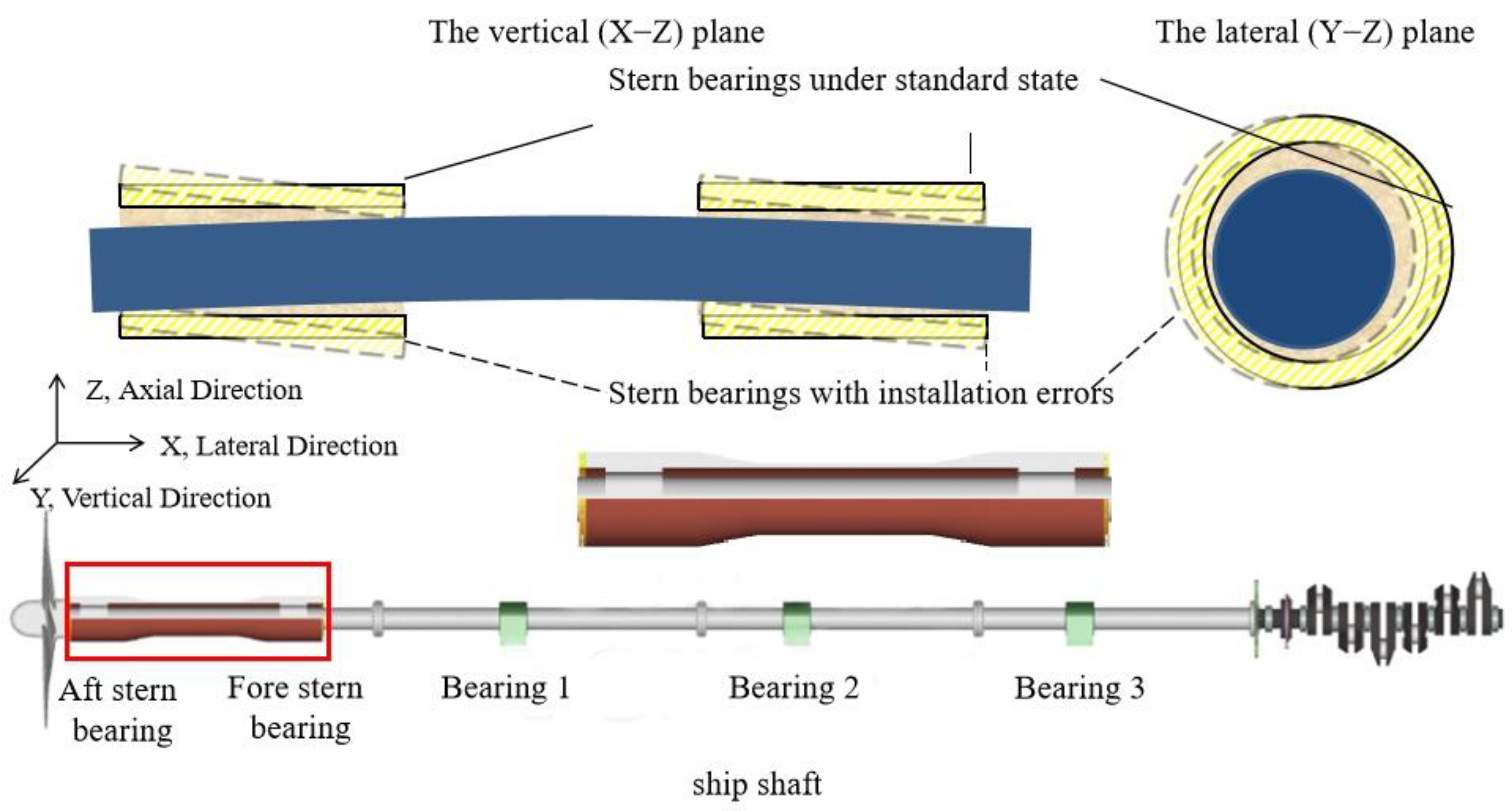
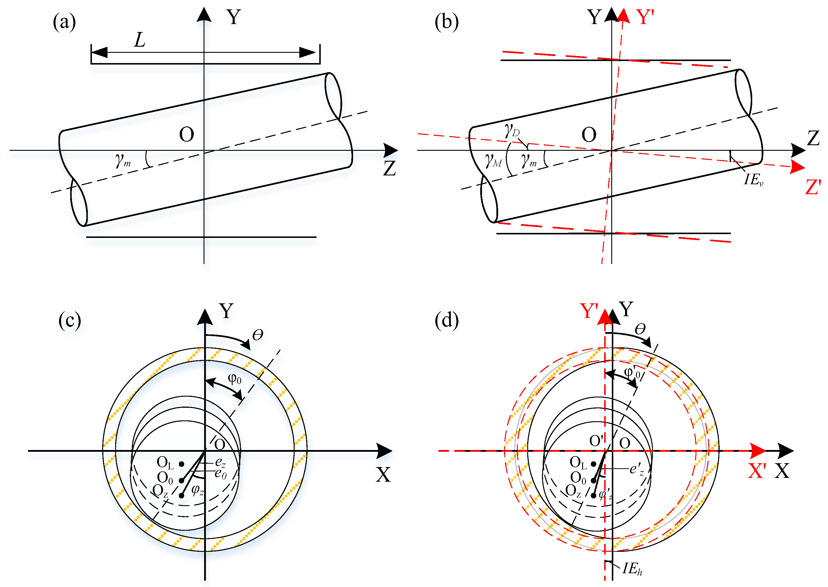
2.1. Mathematical Model of an Inclined Bearing with Installation Errors

In this paper, the Cartesian coordinate system for solving the lubrication performance of the sliding bearing is defined as follows: The origin is at the center of the bearing’s cross-section in the axial middle plane [25,26]. The Z-axis is the axial direction of the coordinate system, the X-axis represents the bearing’s circumferential direction, and the Y-axis represents the radial direction of the bearing.
Figure 2a shows a schematic diagram of the shaft system structure in the Z–Y plane, and Figure 2b shows the schematic diagram of the structure in the X–Y plane. In Figure 2, the solid line is the state of the bearing without installation deviation, the dashed line is the position state of the bearing after the deviation, the circles in Figure 2c, d are the shaft segments and the colored shadow is the bearing. Figure 2a,c illustrate the bearing structure without considering installation errors. As shown in Figure 2a,c, the schematic diagram of the bearing structure without considering installation errors is shown, and γ is the radial inclination angle. The journal rotates clockwise at an angular velocity of ω , and θ is the circumferential angle. O L , O 0 , and O z are the centers of the axial end-plane, axial mid-plane, and each axial section, respectively; φ 0 and φ z are the attitude angle and eccentricity at the axial mid-plane of bearing; and e 0 and e z are the eccentricities of the middle section and each section. By projecting the centers of each axial section along the Z-axis direction to the middle section, the eccentricity and offset angle at any section can be obtained based on the structural schematic diagram. Figure 2b shows a schematic diagram of the bearing that includes the vertical installation error, I E v is the vertical installation error of the bearing, Figure 2b is a schematic diagram of the bearing that includes the lateral installation errors, and I E h is the lateral installation error of the bearing.
As shown in Figure 2a,c, the center distance e z and the offset angle φ z of any section along the axial direction can be obtained based on geometric relationships. The expression is as follows:
e z = z tan γ m 2 + 2 z e 0 tan γ m cos φ 0 + e 0 2
φ z = arctan e 0 sin φ 0 z tan γ m + e 0 cos φ 0
From Figure 2b, based on the geometric relationship, the expression for the radial inclination angle γ M and the center distance e z of any section along the axial direction, including the vertical installation error, can be obtained as follows:
γ M = γ m + arctan I E v L / 2
e z = z tan γ M 2 + 2 z e 0 tan γ M cos φ 0 + e 0 2
From Figure 2d, based on the geometric relationship, the expressions for the center distance e z and offset angle φ z of any section along the axial direction, including the vertical and lateral installation errors, can be obtained as follows:
e z = z tan γ M 2 + 2 z e 0 tan γ M cos φ 0 + e 0 2 + IE h 2 2 e 0 IE h sin φ 0
φ z = arctan e 0 sin φ 0 IE h z tan γ M + e 0 cos φ 0

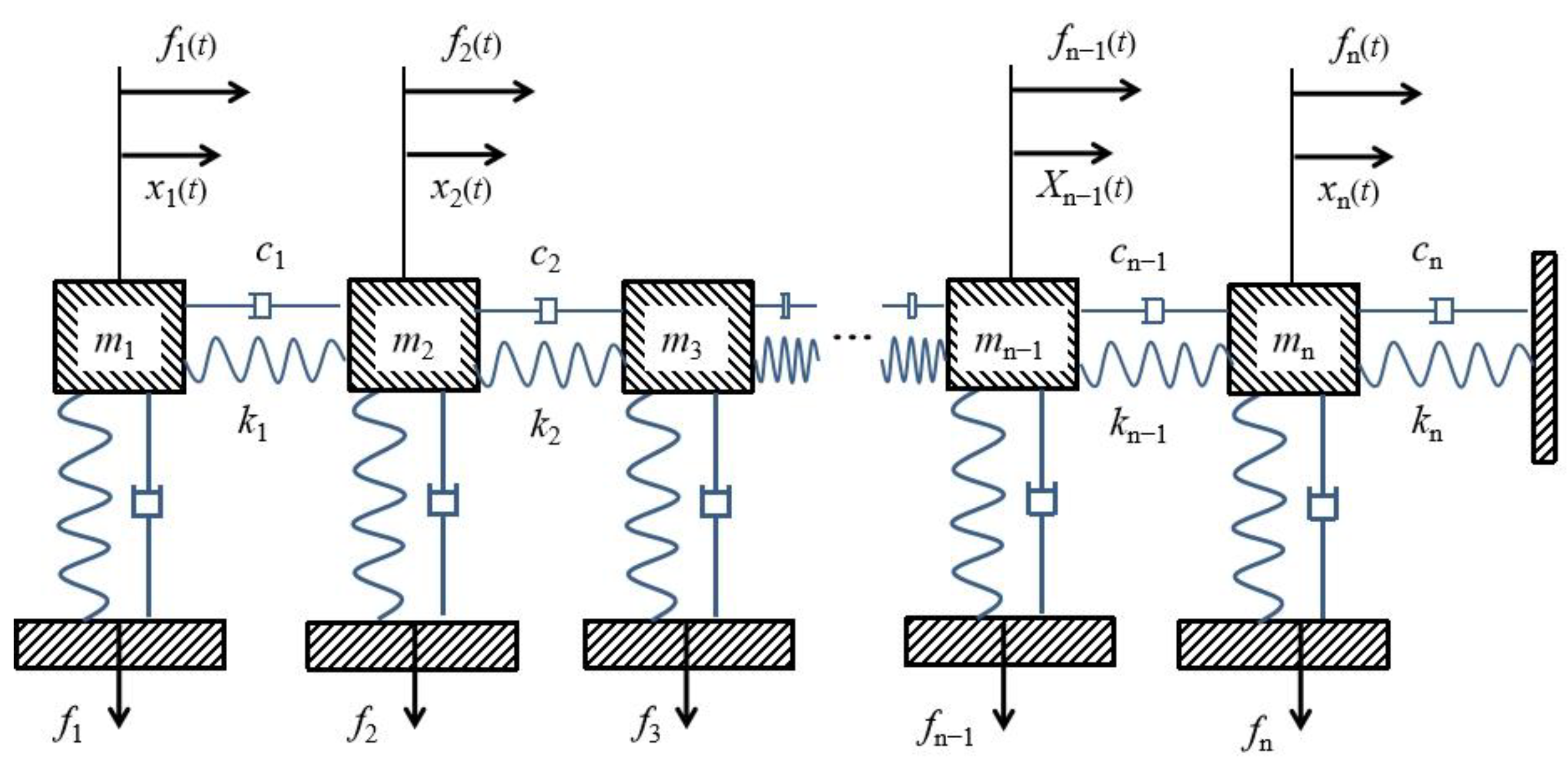
2.2. Equations of Motion for Multi-Degree-of-Freedom Systems

For a discrete system, in a generalized coordinate system, the generalized mass, damping, and stiffness are defined as M , C , and K [27,28], while the generalized acceleration, velocity, displacement, and force are denoted by x ¨ , x ˙ , x , and F . The equation of motion for the system is given by
M x ¨ + C x ˙ + K x = F
In Figure 3, the dynamic equation for a single mass m i in the system is as follows:
m i x ¨ i c i 1 x ˙ i x ˙ i 1 + c i x ˙ i + 1 x ˙ i k i 1 x i x i 1 + k i x i + 1 x i x = 0
The mass matrix, damping matrix, and stiffness matrix are defined as follows [29,30,31,32]:
M = m 1 m 2 m n 1 m n
C = c 1 c 1 c 1 c 1 + c 2 c 2 c n 1 c n 1 + c n c n c n c n
K = k 1 k 1 k 1 k 1 + k 2 k 2 k n 1 k n 1 + k n k n k n k n
x ¨ , x ˙ , and x can be represented as follows:
x ¨ = x ¨ 1 , x ¨ 2 , , x ¨ n ,   x ˙ = x ˙ 1 , x ˙ 2 , , x ˙ n ,   x = x 1 , x 2 , , x n
For a three-degree-of-freedom vibration system without considering damping, the equation of motion of the system is as follows:
m 1 x ¨ 1 + k 1 x 1 k 2 x 2 x 1 = 0 m 2 x ¨ 2 + k 2 x 2 x 1 k 3 x 3 x 2 = 0 m 3 x ¨ 3 + k 3 x 3 x 2 = 0
The solution to Equation (13) is as follows:
x 1 = A 1 sin ω t + φ x 2 = A 2 sin ω t + φ x 3 = A 3 sin ω t + φ
Here, A 1 , A 2 , and A 3 represent the amplitudes of each degree of freedom in the system’s motion, and φ is the initial phase.

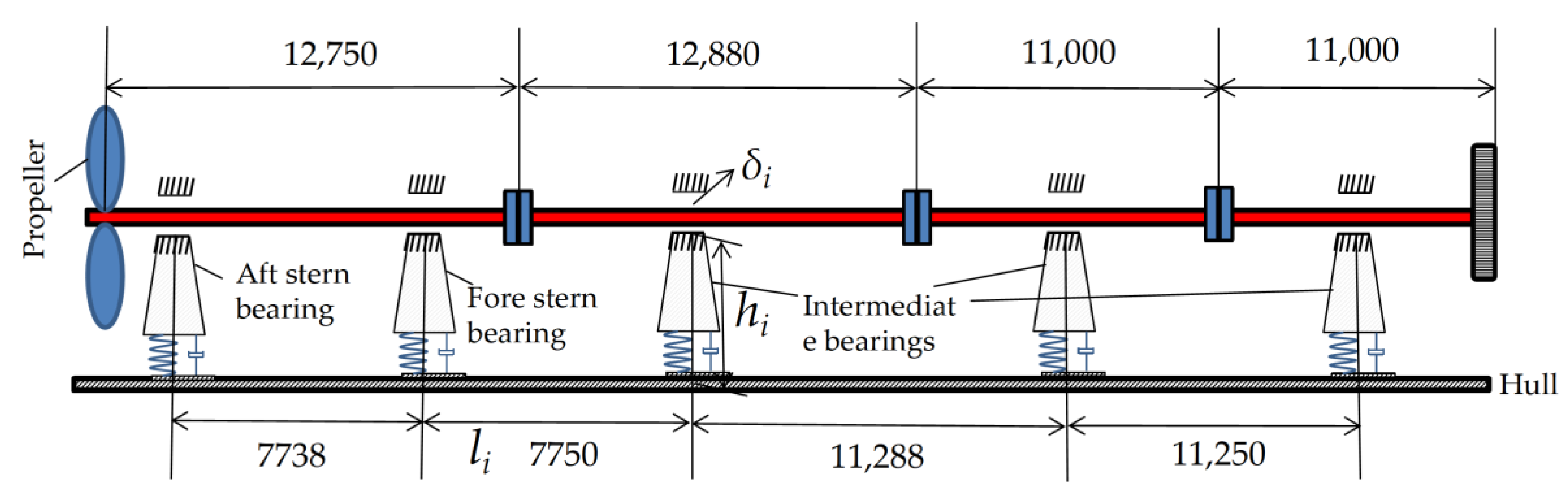
2.3. Motion Equation for Shaft System Considering Bearing Installation Errors

Building on the bearing structure model accounting for installation errors from Section 2.1, as illustrated in Figure 2 for the inclined bearing with installation errors, let D represent the bearing diameter, c represent the bearing clearance, ω b represent the shaft speed, ε = e / c represent the section’s eccentricity, R represent the bearing radius, and μ represent the lubricant viscosity. Define η = c / R as the radial force of the bearing:
f r = D ω b η L 3 ε 2 2 c 2 1 ε 2
The tangential force of the bearing is given by the following:
f t = π D ω b η L 3 ε 8 c 2 1 ε 2 3 / 2
Substituting the center distance of any axial section after accounting for both vertical and lateral installation errors e z , substituting Equation (5) into Equations (15) and (16), the resultant force acting on the bearing is expressed as follows:
f r = D ω b η L 3 z tan γ M 2 + 2 z e 0 tan γ M cos φ 0 + e 0 2 + IE h 2 2 e 0 IE h sin φ 0 2 c 4 1 z tan γ M 2 + 2 z e 0 tan γ M cos φ 0 + e 0 2 + IE h 2 2 e 0 IE h sin φ 0 / c 2
f t = π D ω b η L 3 z tan γ M 2 + 2 z e 0 tan γ M cos φ 0 + e 0 2 + IE h 2 2 e 0 IE h sin φ 0 8 c 3 1 z tan γ M 2 + 2 z e 0 tan γ M cos φ 0 + e 0 2 + IE h 2 2 e 0 IE h sin φ 0 / c 2 3 / 2
For the bearing model, the stiffness matrix and damping matrix of the supporting bearing are defined as follows:
f r e s = f r 2 + f t 2 = π D ω b η L 3 ε 8 c 2 1 ε 2 2 16 π 2 ε 2 + 1 1 / 2
For the bearing model, the stiffness matrix and damping matrix of the supporting bearing are defined as follows:
K = k 0 0 k
C = c 0 0 c
where k and c represent the equivalent stiffness and damping of the bearing. The relationship between the bearing’s speed, displacement, and resultant force on the shaft segment is the following:
f y f z = k u u k u v k v u k v v u v c u u c u v c v u c v v u ˙ v ˙
Here, f y represents the force along the Y axis, f z represents the force along the Z axis, u represents the bearing’s displacement along the Y axis, and v represents the displacement along the Z axis.
The propeller mounted on the shaft system in the coordinate system is represented as X p , Y p , Z p , with I v being the vertical moment of inertia, I l being the horizontal moment of inertia, F Y being the vertical force of the propeller, and F X being the horizontal force. Based on beam theory and Newton’s second law of motion, and neglecting the coupling effect of vibration, the equation of motion for the propulsion shaft system in the vertical direction is as follows:
2 Z 2 E I v 2 x v Z 2 + F Y Δ Z Z p + i = 1 n f y i Δ Z Z i = m ^ Δ x ¨ v + I v Δ 2 x ¨ v Z 2
The equation of motion for the propulsion shaft system in the horizontal direction is as follows:
2 Z 2 E I l 2 x l Z 2 + F X Δ Z Z p + i = 1 n f x i Δ Z Z i = m ^ Δ x ¨ l + I l Δ 2 x ¨ l Z 2

3. Numerical Solution and Model Verification

A finite difference method is used to solve the differential equations, and integration formulas are established. It is assumed that the displacement, velocity, and acceleration changes in the vibrating system within a time interval Δ t allow for the calculation of the motion equation solution. Assuming that the initial displacement, velocity, and acceleration are known, let T represent the time region for solving the vibrating system’s motion equation, and n represent the time interval; then, Δ t = T / n can be obtained, and let a ¨ t be the acceleration of the vibrating system, a ˙ t be the velocity of the vibrating system, and a t be the displacement of the vibrating system; then, a ¨ t and a ˙ t can be expressed as follows:
a ¨ t = 1 Δ t 2 a t Δ t 2 a t + a t + Δ t
a ˙ t = 1 2 Δ t a t Δ t + a t + Δ t
The motion equation can then be written as follows:
M a ¨ t + C a ˙ t + K a t = F t
Substituting Equations (25) and (26) into Equation (27) gives the central difference method’s recursive formula:
1 Δ t 2 M + 1 2 Δ t C a t + Δ t = F t K 2 Δ t 2 M a t 1 Δ t 2 M + 1 2 Δ t C a t Δ t
Equation (28) provides the recursive formula for the motion of the vibrating system at discrete points with a time interval T within the time period Δ t . Using the defined initial conditions, the motion at each discrete point can be computed.
This paper uses the vibration calculation results of a real ship’s propulsion shaft system from reference [33,34,35] for verification. The shaft system has a total length of 18.39 m and a rated speed of 200 r/min. It includes one propeller, one aft bearing, one forward bearing, and three intermediate bearings. The water mass attached to the propeller is 8625 kg, and the moment of inertia is 5388 kg·min2. The measurement sensors in reference [33] were the following: The vibration tester is the YDZT-2013 type shaft system vibration tester jointly developed by Wuhan University of Technology and Wuhan Institute of Standardization of China Classification Society. The eddy current transducer is used to synchronize the testing of two sections of the shaft system, transducer 1 channel Y is the horizontal data of the measurement point in front of the compartment (measurement point 1), and channel Z is the vertical data of measurement point 1; transducer 2 channel Y is the horizontal data of the measurement point after the thrust bearing (measurement point 2), and channel Z is the vertical data of measurement point 2.
The measurements in reference [33] were carried out as follows:
(1)
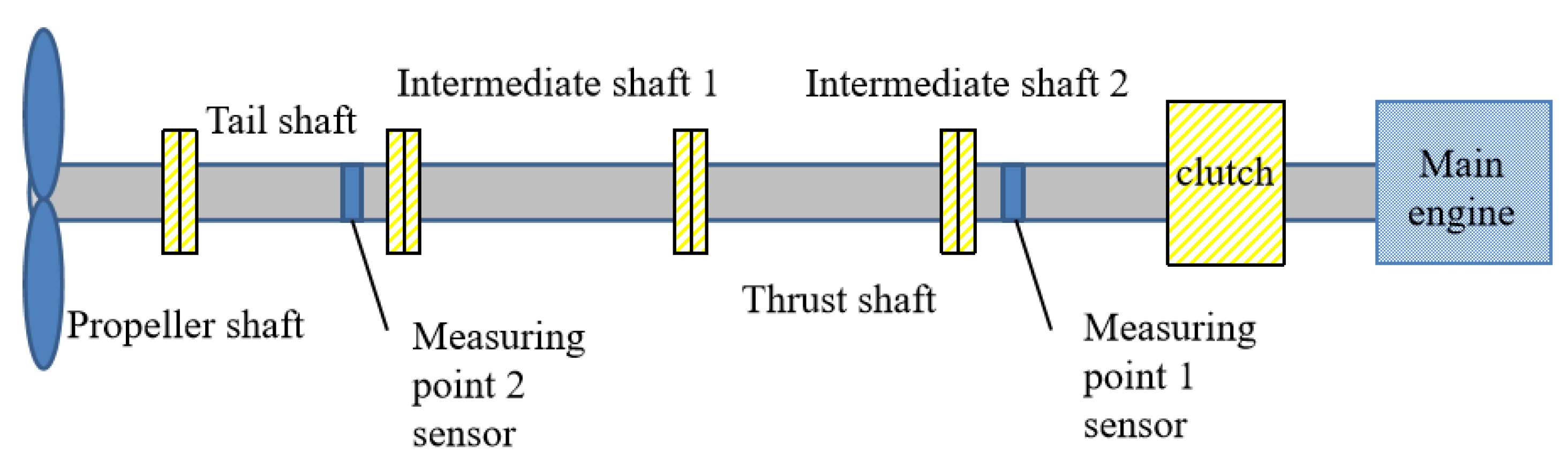
Carrying out the assembly of test bench components, calculating the distance between the tail bearing and the middle bearing in equal proportions, adjusting the position of the middle bearing, and marking the initial elevation and lateral position of the bearing.
(2)
Connect the loading device, testing device, record output device, and other test bench systems.
(3)
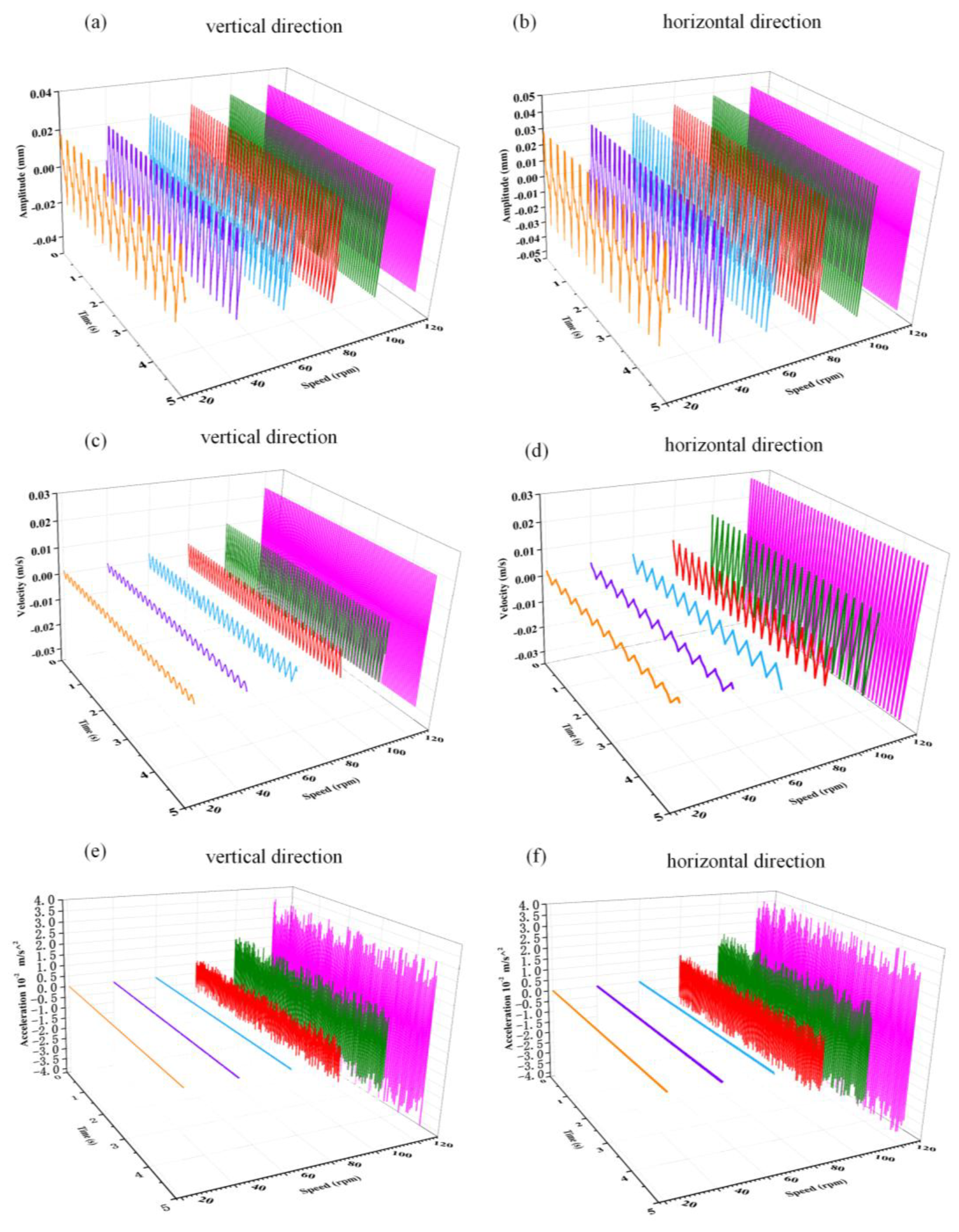
Apply the propeller excitation force through the loading device, and the test motor speeds are 80 r/min, 85 r/min, 90 r/min, 95 r/min, 100 r/min, 105 r/min, 110 r/min, 115 r/min, 120 r/min, 125 r/min, 130 r/min, 135 r/min, 140 r/min, 145 r/min, 150 r/min, 155 r/min, 160 r/min, 165 r/min, 170 r/min, 175 r/min, 180 r/min, 185 r/min, 190 r/min, 195 r/min, and 200 r/min.
(4)
Run the test bench sequentially at different speeds, and collect the vibration signals at test point 1 and test point 2 when the test bench system is working stably.
In this paper, the results of the propulsion shaft system vibration calculations of a real ship in reference [33] are used as an example of computational validation, and the computational data and measurement data in reference [33] are used to compare and analyze. The arrangement of measurement points for the theoretical calculations and tests carried out in reference [33] is shown in Figure 4. The comparison of the calculation results of this paper with the theoretical calculation results and test results in reference [33] is shown in Figure 5 as a comparison graph of the amplitude change, in which the solid line indicates the trend in amplitude change with rotational speed for measurement point 1, and the dashed line indicates the trend in amplitude change with rotational speed for measurement point 2. From the graph, it is clear that the amplitude variations at measurement points 1 and 2 in this paper follow the same trend as in reference [33]. Specifically, the maximum error at measurement point 1 between the theoretical calculation in reference [33] and this paper’s calculation is 14.93%, with a minimum error of 0.38%. The maximum error between the experimental test in reference [33] and this paper’s calculation at measurement point 1 is 16.09%, with a minimum error of 0.36%. For measurement point 2, the maximum error between the theoretical calculation in reference [33] and this paper’s result is 4.89%, with a minimum error of 0.50%. The maximum error for the experimental test at measurement point 2 is 13.79%, with a minimum error of 1.64%.

4. Discussion

This paper focuses on a container ship and investigates the dynamic characteristics of its propulsion shaft system under the influence of various aft bearing installation errors [36,37]. The composition and structure of the ship’s propulsion shaft system are shown in Figure 6. The shaft system includes one aft bearing, one forward bearing, and three intermediate bearings, forming a multi-point long shaft system. The bearing parameters are listed in Table 1, the basic parameters of the shaft segments are shown in Table 2, and the propeller parameters are given in Table 3. The main engine power is 68,520 kW, with a rated speed of 100 r/min.

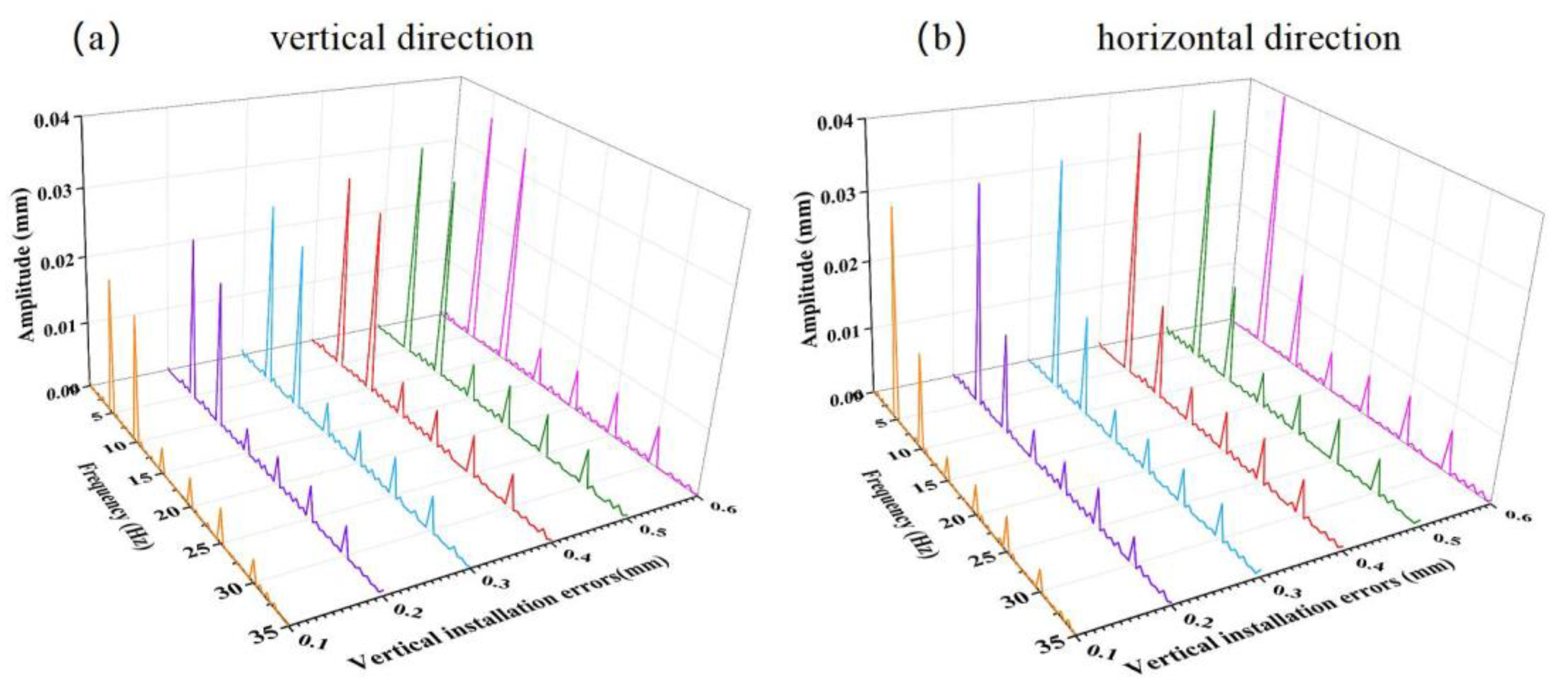
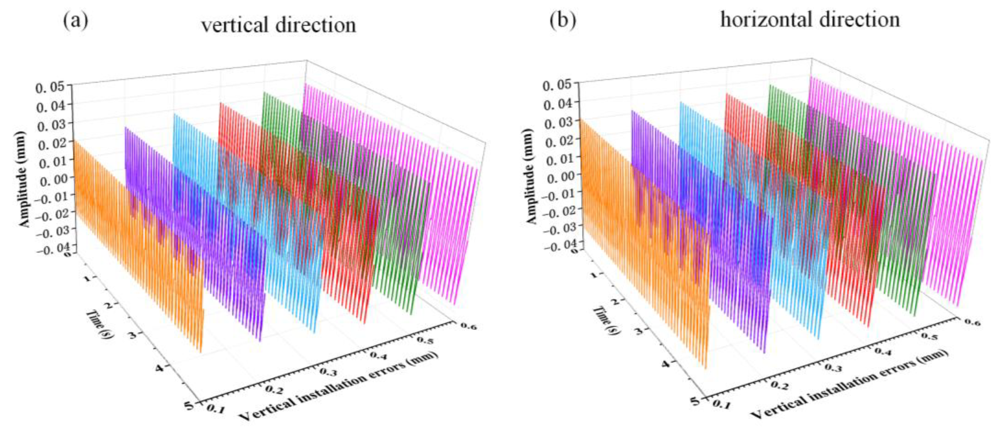
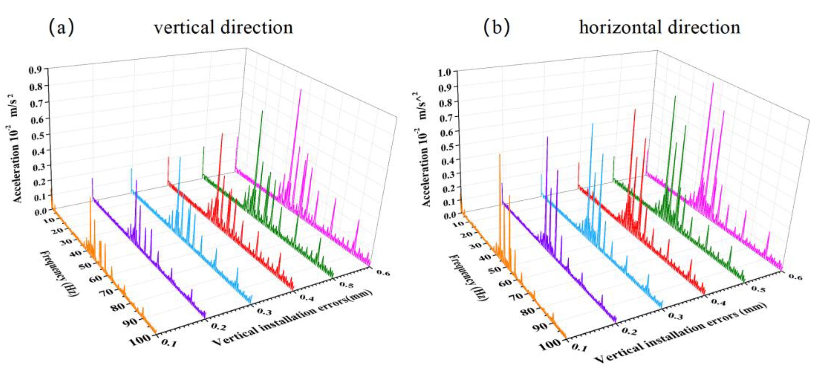
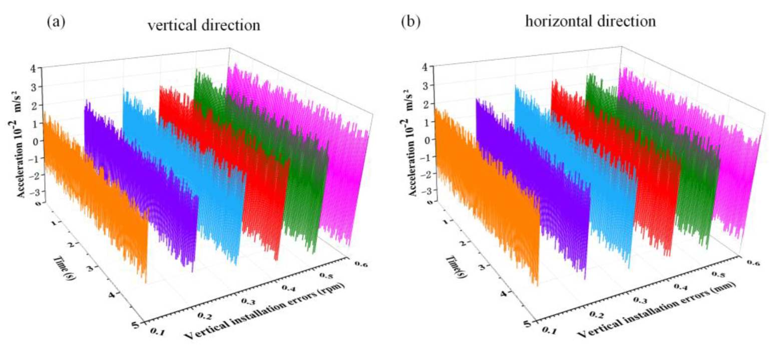
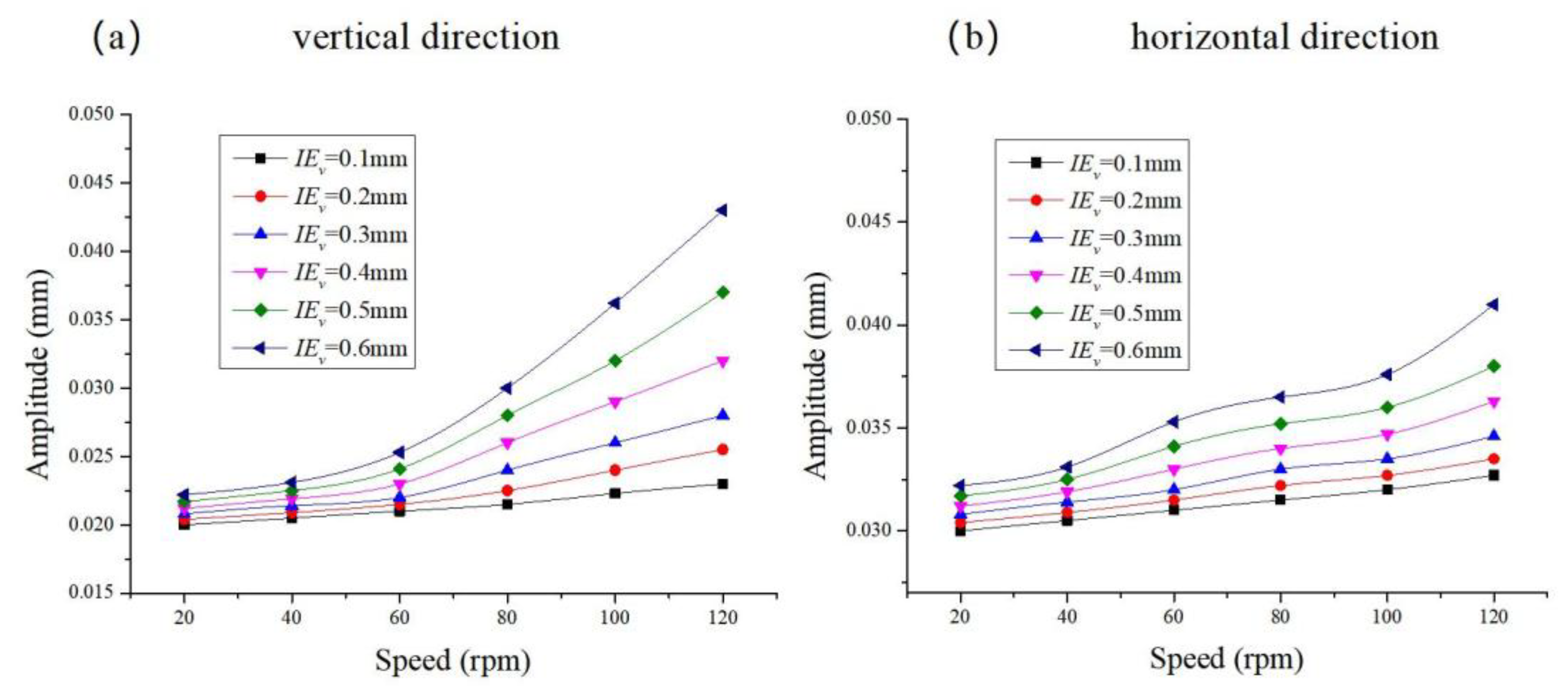
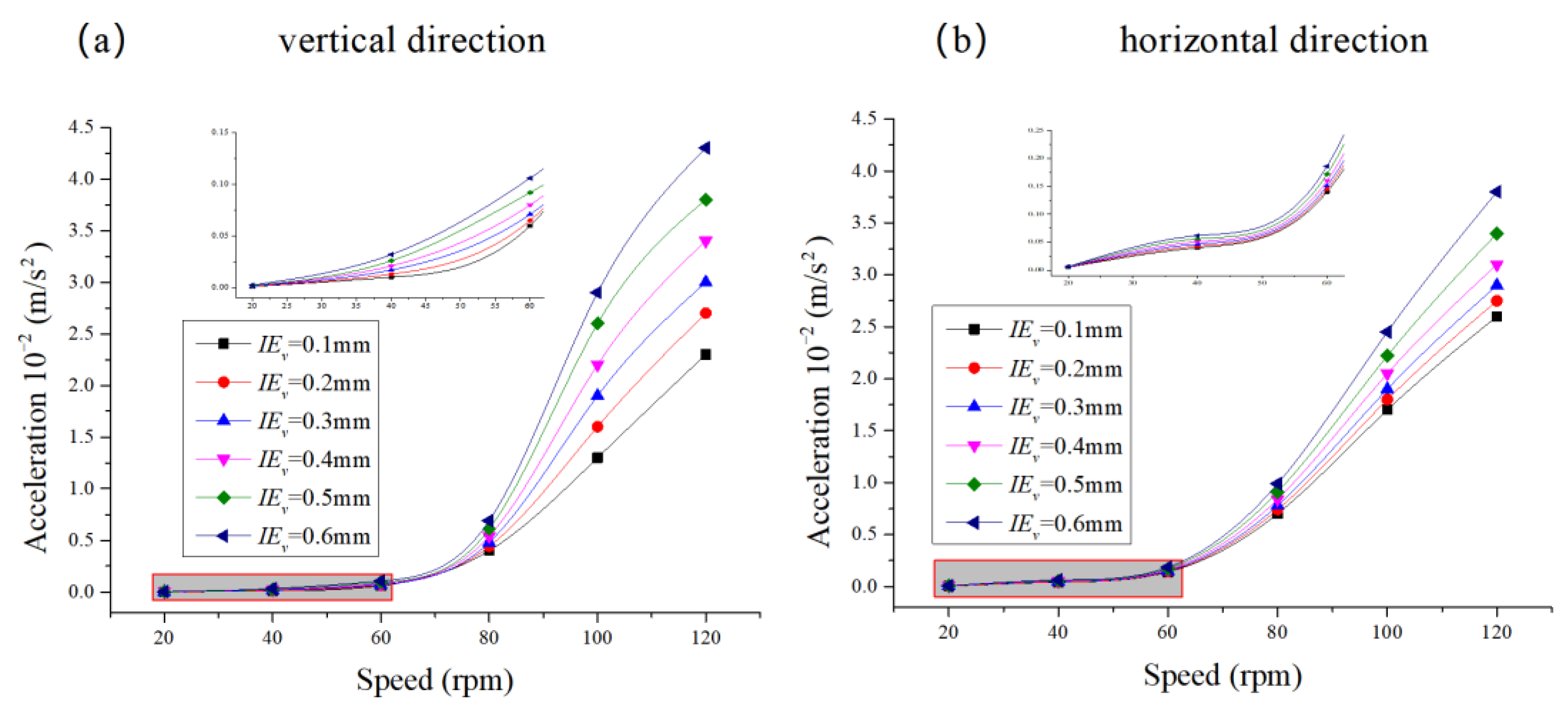
4.1. Analysis of the Impact of Bearing Vertical Installation Errors on Vibration

As shown in Figure 7, the variation response spectra of the vibration amplitude, velocity, and acceleration of the propeller shaft system’s precession vibration in the range of 20–120 r/min, with no vertical bearing installation error, are provided. The orange, purple, blue, red, green, and pink lines in Figure 7 represent the variation curves at 20 r/min, 40 r/min, 60 r/min, 80 r/min, and 120 r/min, respectively. Figure 7a,b show the precession vibration amplitude spectra, Figure 7c,d show the precession vibration velocity spectra, and Figure 7e,f show the precession vibration acceleration spectra. Among these, Figure 7a,c,e are the vibration spectra in the vertical direction, while Figure 7b,d,f are the vibration spectra in the horizontal direction. From Figure 7a,b, it can be seen that the precession vibration amplitude of the propeller shaft system increases with the rotational speed in both the horizontal and vertical directions, with the increase in the horizontal direction being greater than in the vertical direction. From Figure 7c,d, it can be seen that the precession vibration velocity of the propeller shaft system also increases with the rotational speed in both directions, with the increase in the horizontal direction being greater than in the vertical direction. From Figure 7e,f, it can be seen that the precession vibration acceleration of the propeller shaft system increases with the rotational speed in both directions, with the increase in the horizontal direction being greater than in the vertical direction. From Figure 7, it can be seen that under the same rotational speed and no vertical error in the bearing installation, the amplitude, speed, and acceleration of the gyration vibration of the paddle shaft system in the horizontal direction are larger than those in the vertical direction, which is due to the following reasons:
Directional difference in the support stiffness of the shaft system: the support stiffness of the shaft system of a ship is usually lower than that of the vertical direction, which results in a larger deformation in the horizontal direction due to the installation error.
The coupling effect of gravity load: the vertical direction is affected by the self-weight of the shaft system, and the oil film pressure distribution is relatively stable, while there is no gravity load in the horizontal direction, and the installation error will directly break the balance of the oil film pressure and aggravate the vibration.
Directionality of propeller excitation: the horizontal hydrodynamic excitation generated by propeller rotation is more significant in the horizontal direction, which is amplified by the coupling with the installation error.
As shown in Figure 7, the sensitivity to mounting errors is lower at speeds below 60 r/min due to the following reasons:
Mechanical inertia and damping dominance: at lower speeds, the inertial forces of the system and the damping effects of the lubricant dominate over the excitation caused by mounting errors, which suppresses the vibration response and weakens the effect of the errors.
Resonance avoidance: most marine propulsion shaft systems typically have a natural frequency above 60 rpm; below this threshold, the system operates in a sub-critical state with little resonance amplification due to mounting errors.
Lubrication stability: At low speeds, the bearing oil film is more stable, reducing susceptibility to misalignment problems. As speed increases, oil film rupture and dynamic load fluctuations can amplify the effects of mounting errors.
The magnitude frequency spectra of the propeller shaft system with different vertical errors at the rated speed of 100 r/min are shown in Figure 8. Figure 8a shows the magnitude frequency spectrum in the vertical direction, and Figure 8b shows the magnitude frequency spectrum in the horizontal direction. From Figure 8, it can be seen that at the rated speed, both the vertical and horizontal magnitude of the propeller shaft system increase with the bearing vertical installation error. In Figure 7a, the vertical magnitude frequency spectrum has two peaks, with the maximum peak frequency at 4.95 Hz and the second peak frequency at 10.3 Hz. In Figure 8b, the horizontal magnitude frequency spectrum has one peak, with the peak frequency at 5.06 Hz.
Figure 9 shows the magnitude transient response of the propeller shaft system with different vertical errors at the rated speed of 100 r/min. Both the vertical and horizontal magnitude transient responses of the propeller shaft system increase with the bearing vertical installation error. Under the same vertical installation error, the horizontal transient magnitude is greater than the vertical.
As shown in Figure 10, the vibration acceleration frequency spectra of the propeller shaft system with different vertical installation errors at the rated speed of 100 r/min are shown. Figure 10a shows the vibration acceleration frequency spectrum in the vertical direction. From the graph, it can be seen that as the bearing vertical installation error increases, the vibration acceleration amplitude of the propeller shaft system increases, with the main amplitude range concentrated between 35 Hz and 55 Hz, and the peak frequency at 38.7 Hz. Figure 10b shows the vibration acceleration frequency spectrum in the horizontal direction. From the graph, it can be seen that the main amplitude range is also concentrated between 35 Hz and 55 Hz, with two peaks: the first peak frequency at 39.2 Hz and the second peak frequency at 53.7 Hz. As the bearing vertical installation error increases, the vibration acceleration amplitude increases. Comparing Figure 10a,b, it can be seen that the increase in vertical vibration acceleration is greater than in the horizontal direction as the bearing vertical installation error increases.
The vibration acceleration transient response of the propeller shaft system with different vertical installation errors at the rated speed of 100 r/min is shown in Figure 11. From the graph, it can be seen that as the bearing vertical installation error increases, the vibration acceleration transient response amplitude increases in both the vertical and horizontal directions. When the bearing vertical installation error is 0.1 mm, the vertical vibration acceleration transient response is smaller than the horizontal vibration acceleration transient response. However, when the bearing vertical installation error is 0.6 mm, the vertical vibration acceleration transient response is greater than the horizontal vibration acceleration transient response. This indicates that as the bearing vertical installation error increases, the increase in the vertical vibration acceleration transient response is greater than in the horizontal direction, and the vertical vibration acceleration transient response is more sensitive to the bearing vertical installation error than the horizontal direction.
As shown in Figure 12, the vibration amplitude of the propeller shaft system with different vertical installation errors changes with the rotational speed. From the graph, it can be seen that both the vertical and horizontal vibration amplitudes increase with the rotational speed and also increase with the bearing vertical installation error. As the bearing vertical installation error increases, the increase in vertical and horizontal vibration amplitudes also increases, indicating that the impact of the bearing vertical installation error on the vibration amplitude of the propeller shaft system gradually increases. When the bearing vertical installation error is 0.1 mm, the increase in vertical vibration amplitude is similar to the increase in the horizontal vibration amplitude. However, as the bearing vertical installation error increases, the increase in the vertical vibration amplitude becomes greater than in the horizontal direction, indicating that the bearing vertical installation error has a larger impact on the vertical vibration amplitude than on the horizontal vibration amplitude.
As shown in Figure 13, the vibration acceleration response curve of the propeller shaft system with different vertical installation errors changes with the rotational speed. From the graph, it can be seen that when the rotational speed of the propeller shaft system is less than 60 r/min, the bearing vertical installation error has no significant impact on the vibration acceleration of the propeller shaft system. However, when the rotational speed is greater than 60 r/min, the bearing vertical installation error gradually increases the impact on vibration acceleration. The local magnification of Figure 13a,b shows that when the rotational speed of the propeller shaft system is less than 60 r/min, the trend is the same as when the rotational speed is greater than 60 r/min; i.e., both vertical and horizontal vibration acceleration amplitudes increase with the rotational speed and also increase with the bearing vertical installation error. As the bearing vertical installation error increases, the increase in vertical and horizontal vibration acceleration amplitudes gradually becomes more pronounced, indicating that the effect of bearing vertical installation error on the vibration acceleration of the propeller shaft system increases. Furthermore, as the bearing vertical installation error increases, the increase in vertical vibration acceleration amplitude is greater than in the horizontal direction, indicating that the effect of bearing vertical installation error on vertical vibration acceleration is more significant than on horizontal vibration acceleration.

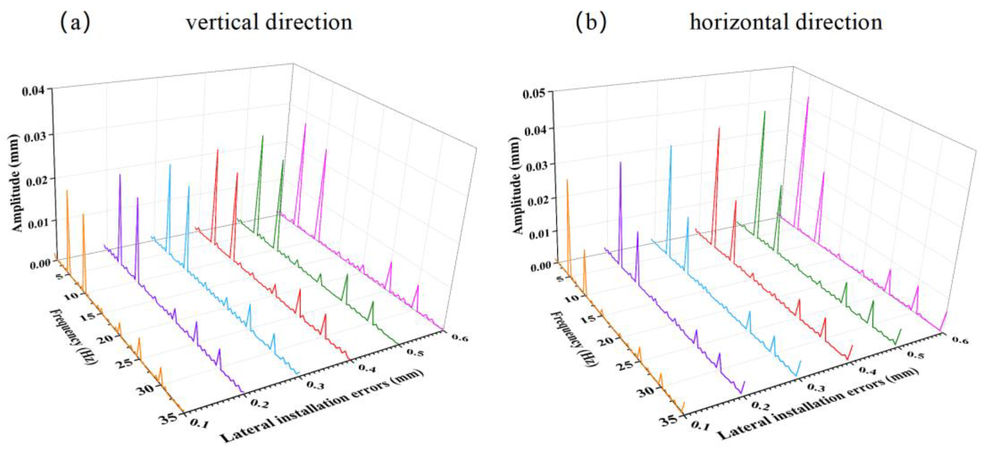
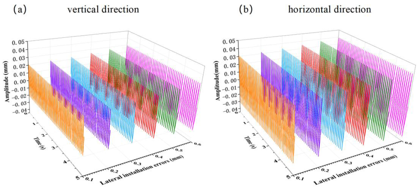
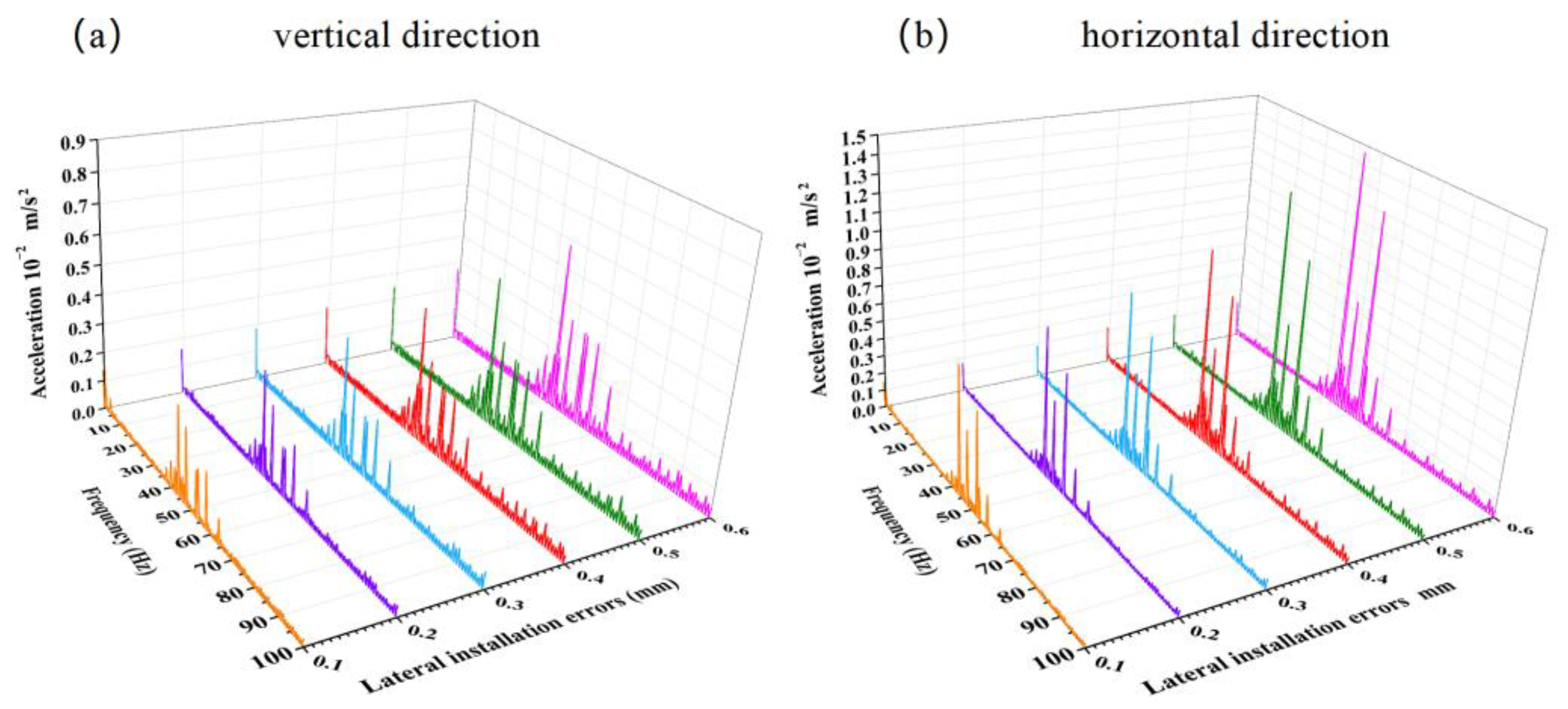
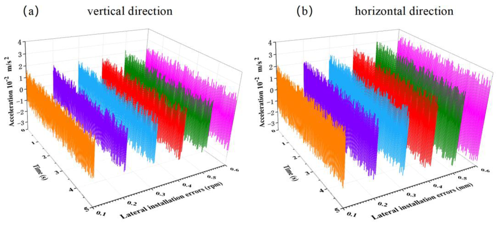
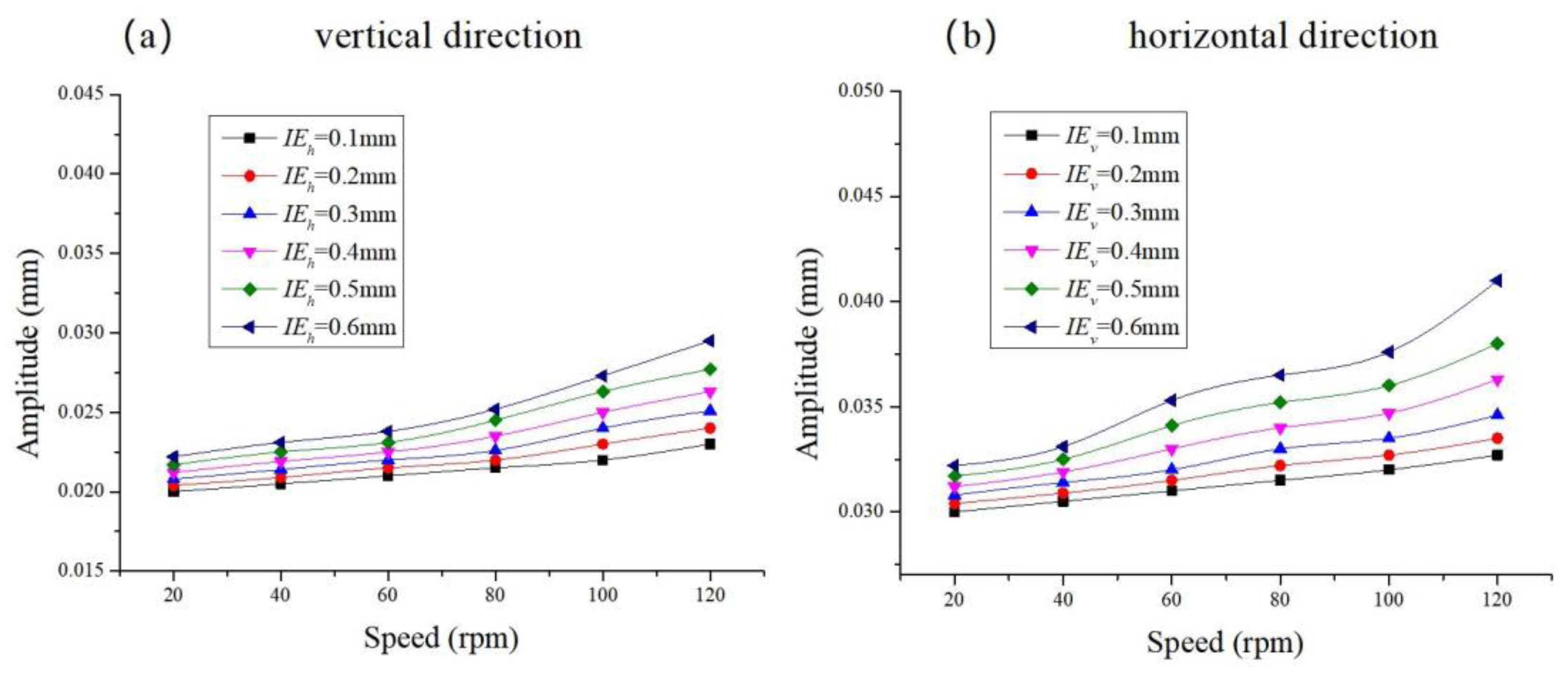
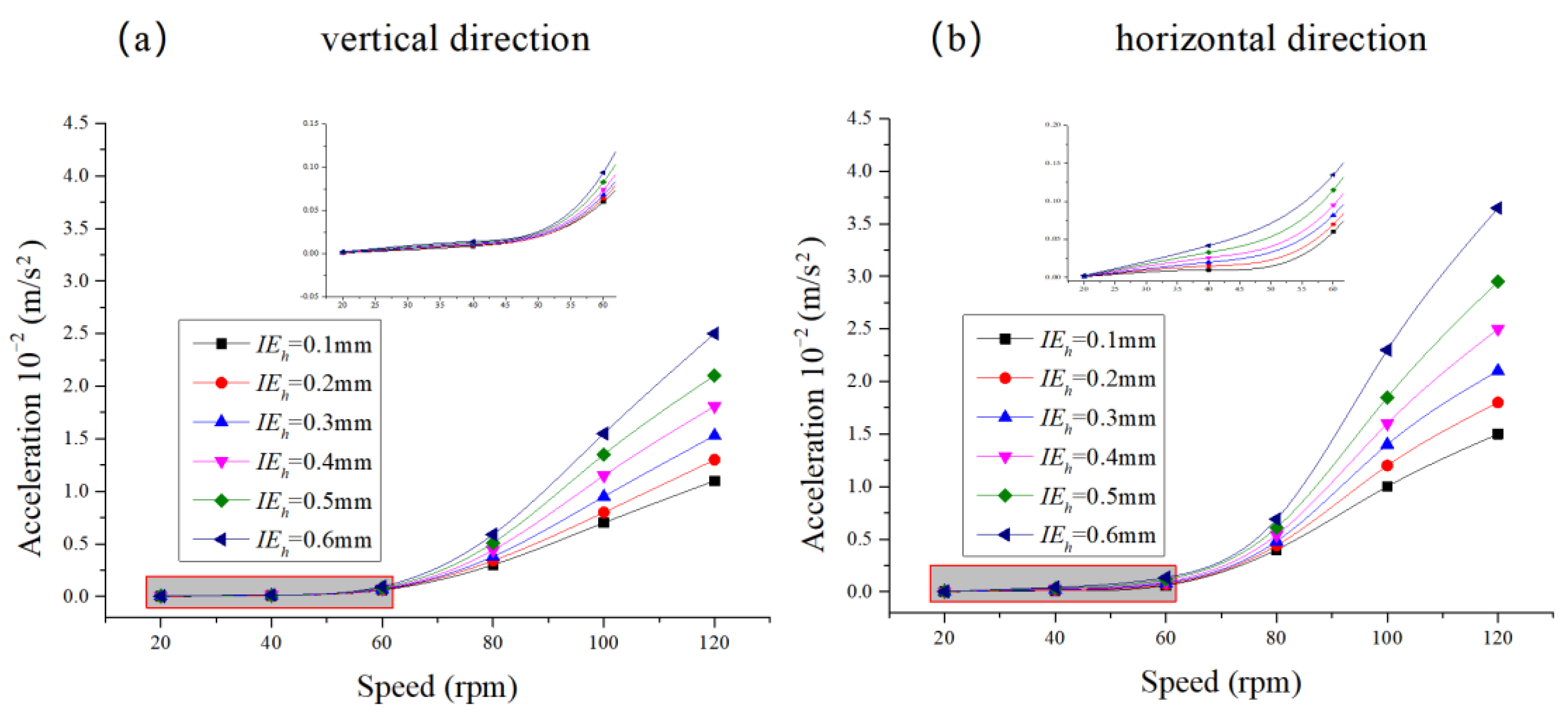
4.2. Analysis of the Impact of Bearing Lateral Installation Errors on Vibration

Figure 14 shows the magnitude frequency spectra of the propeller shaft system with different lateral installation errors at the rated speed of 100 r/min. Figure 14a presents the magnitude frequency spectrum in the vertical direction, while Figure 14b shows the spectrum in the horizontal direction. At the rated speed, the magnitudes in both directions increase with the increase in the bearing lateral installation errors. In Figure 14a, the vertical magnitude frequency spectrum has two peaks, with the maximum frequency at 4.83 Hz and the second peak at 9.8 Hz. In Figure 14b, the horizontal magnitude frequency spectrum has one peak at 4.98 Hz. It is evident that with the increase in bearing lateral installation errors, the vibration amplitude in the horizontal direction increases more significantly than in the vertical direction.
Figure 15 presents the magnitude transient response of the propeller shaft system with different lateral installation errors at the rated speed of 100 r/min. The magnitude transient responses in both the vertical and horizontal directions increase with the bearing lateral installation error. Under the same error, the horizontal transient magnitude is larger than the vertical one, with a greater increase in the horizontal direction.
As shown in Figure 16, the vibration acceleration frequency spectra of the propeller shaft system with different lateral installation errors at the rated speed of 100 r/min are shown. In Figure 16a, the vertical vibration acceleration spectrum shows an increase in amplitude as the bearing lateral installation error grows, with the main amplitude concentrated between 35 Hz and 63 Hz, peaking at 39.3 Hz. In Figure 16b, the horizontal vibration acceleration spectrum also shows an increase, with a concentration between 35 Hz and 58 Hz, and two peaks at 40.8 Hz and 52.6 Hz. The increase in vibration acceleration in the horizontal direction is larger than in the vertical direction.
Figure 17 shows the vibration acceleration transient response of the propeller shaft system with different lateral installation errors at the rated speed of 100 r/min. As the lateral installation error increases, the transient response amplitudes in both the vertical and horizontal directions increase. The increase in the horizontal transient response is greater than in the vertical direction, suggesting that the horizontal vibration acceleration is more sensitive to bearing lateral installation errors.
Figure 18 shows how the vibration amplitude of the propeller shaft system changes with the rotational speed for different lateral installation errors. Both vertical and horizontal vibration amplitudes increase with the rotational speed and with the bearing lateral installation error. As the installation error increases, the rate of increase in vibration amplitude becomes more significant, particularly in the horizontal direction.
Figure 19 shows how the vibration acceleration of the propeller shaft system changes with the rotational speed for different lateral installation errors. When the rotational speed is less than 60 r/min, the bearing lateral installation error has little effect on the vibration acceleration. However, as the speed exceeds 60 r/min, the effect of the lateral installation error increases. The trend for both vertical and horizontal vibration acceleration amplitudes increases with rotational speed and bearing error, with a more pronounced increase in the horizontal direction.

5. Conclusions

This chapter combines multi-degree-of-freedom system dynamics theory to investigate the effects of bearing vertical and lateral installation errors on the shaft system vibration performance. It establishes the equations of motion for the shaft system, accounting for bearing installation errors, and analyzes the sensitivity of the propeller shaft system’s vibration response to these errors. The main conclusions are as follows:
(1)
As the bearing vertical installation error increases, the increase in vibration amplitude in both the vertical and horizontal directions becomes more significant. The effect of vertical installation errors on the vertical vibration amplitude is more pronounced than on the horizontal direction. The impact on vibration acceleration also increases, with a greater increase in vertical vibration acceleration compared to the horizontal direction. The vertical vibration acceleration is more sensitive to bearing vertical installation errors than the horizontal direction.
(2)
As the bearing lateral installation error increases, the increase in vibration amplitude is more significant in the horizontal direction than in the vertical direction. The sensitivity of the horizontal vibration amplitude to bearing lateral installation errors is greater than in the vertical direction.
(3)
As the bearing lateral installation error grows, the increase in vibration acceleration amplitude in both the vertical and horizontal directions becomes more pronounced. The effect of the bearing lateral installation errors on the vibration acceleration of the propeller shaft system increases, with a larger increase in vibration acceleration in the horizontal direction compared to the vertical direction. The horizontal vibration acceleration is more sensitive to lateral installation errors than the vertical vibration acceleration.

Author Contributions

Formal analysis, S.F. and H.Z.; project administration, J.Z.; validation, Y.Z. and H.W.; visualization, J.Y.; writing—original draft, T.Y. All authors have read and agreed to the published version of the manuscript.

Funding

This research was financially supported by the Scientific Research Project of China COSCO Shipping Group under grant no. 2023-2-Z002-07. This research was financially supported by the National Natural Science Foundation of China under grant no. U2341284.

Data Availability Statement

The original contributions presented in this study are included in the article. Further inquiries can be directed to the corresponding author.

Conflicts of Interest

J.Z., Y.Z., H.W. and T.Y. are employed by COSCO Shipping Heavy Industry (Zhoushan) Co., Ltd. The research was conducted in the absence of any commercial or financial relationships that could be construed as a potential conflict of interest.

Abbreviations

The following abbreviations are used in this manuscript:
γ radial inclination angle
ω angular velocity
θ circumferential angle
O L centers of axial end-plane
O 0 axial mid-plane
O z each axial section, respectively
φ 0 attitude angle
φ z eccentricity at the axial mid-plane
e 0 eccentricity of the middle section
e z eccentricity of each section
I E v vertical installation error
I E h lateral installation error
M discrete system: the generalized mass
C discrete system: the generalized damping
K discrete system: the generalized stiffness
x ¨ generalized acceleration
x ˙ generalized velocity
x generalized displacement
F generalized force
M mass matrix
C damping matrix
K stiffness matrix
m i single mass
c i damping
k i stiffness
A i the amplitudes of each degree of freedom in the system’s motion
φ the initial phase
D the bearing diameter
c the bearing clearance
ω b the shaft speed
ε the section’s eccentricity
R the bearing radius
f r the radial force of the bearing
f t the tangential force of the bearing
f r e s the resultant force acting on the bearing
f y the force along the Y axis
f z the force along the Z axis
u the bearing’s displacement along the Y axis
v the displacement along the Z axis
I v the vertical moment of inertia
I l the horizontal moment of inertia
F Y the vertical force of the propeller
F X the horizontal force
Δ t time interval
T the time region for solving the vibrating system’s motion equation
a ¨ t the acceleration of the vibrating system
a ˙ t the velocity of the vibrating system
a t the displacement of the vibrating system

References

  1. Yang, T.; Zhu, H.; Fan, S.; Wu, J.; Yuan, J.; Zheng, L. Research on Lubrication Characteristics of Ship Stern Bearings Considering Bearing Installation Errors. Lubricants 2023, 11, 478. [Google Scholar] [CrossRef]
  2. Wu, C.; Long, X.; Shang, D.; Chen, F. Investigation on the influence of bearing certainty and random elevation on the friction self-excited vibration of ship propeller shaft system. J. Sound Vib. 2025, 608, 119034. [Google Scholar] [CrossRef]
  3. Zhang, X.; Wang, Y.; Wang, K.; Jin, H.; Liu, W.; Li, Z. Nonlinear vibration of a propeller propulsion shafting with frictional and magnetic excitations of journal and thrust bearings. Mech. Syst. Signal Process. 2025, 230, 112660. [Google Scholar] [CrossRef]
  4. Guo, Y.; Zhou, R.; Ma, Z.; Wang, J.; Ding, L. Research on the Dynamic Response Characteristics of the Propulsion Shaft System with an On-Shaft Generator in Ships. Appl. Sci. 2024, 14, 6769. [Google Scholar] [CrossRef]
  5. Lu, L.; Li, G.; Xing, P.; Gao, H.; Song, Y. A review of stochastic finite element and nonparametric modelling for ship propulsion shaft dynamic alignment. Ocean. Eng. 2023, 286, 115656. [Google Scholar] [CrossRef]
  6. Li, C.; Hao, W.; Lei, W.; Liu, M.; Hua, H. Vibro-acoustic responses of a hull due to structural and acoustic excitations from a propeller. Ocean. Eng. 2023, 276, 114168. [Google Scholar] [CrossRef]
  7. Zou, D.; Zhang, J.; Ta, N.; Rao, Z. Study on the axial exciting force characteristics of marine propellers considered the effect of the shaft and blade elasticity. Appl. Ocean. Res. 2019, 89, 141–153. [Google Scholar] [CrossRef]
  8. Shu, M.-H.; Chen, K.; You, Y.-X.; Hu, T.-Q.; Wang, R.-F. Numerical study on variation characteristics of the unsteady bearing forces of a propeller with an external transverse excitation. J. Hydrodyn. 2019, 31, 400–412. [Google Scholar] [CrossRef]
  9. Aliasghar, M.; Mohammadreza, G.; Alireza, N.; Hassan, B. Investigating the effect of blade tip bending (winglet) on efficiency and occurrence of cavitation of a submerged propeller. Ocean. Eng. 2025, 319, 120254. [Google Scholar]
  10. Anna Maria, K.; Sverre, S.; Lynn Rebecca, M. Slamming and dynamic loads of marine propellers operating under partially submerged conditions. Ocean. Eng. 2025, 335, 121733. [Google Scholar]
  11. Zou, D.; Lv, F.; Ta, N.; Rao, Z. Study on bearing force of marine propeller induced by longitudinal vibration of propulsion-shafting. Ships Offshore Struct. 2020, 15, 162–173. [Google Scholar] [CrossRef]
  12. Zou, D.; Zhang, J.; Liu, G.; Ta, N.; Rao, Z. Study on characteristics of propeller exciting force induced by axial vibration of propulsion shafting: Theoretical analysis. Ocean. Eng. 2020, 202, 106942. [Google Scholar] [CrossRef]
  13. Wu, J.-S.; Sheu, J.-J. An Exact Solution for Whirling Speeds and Mode Shapes of Multi-span Rotating Shafts with Each Span Carrying a Number of Rigid Disks. J. Vib. Eng. Technol. 2022, 10, 149–174. [Google Scholar] [CrossRef]
  14. Guo, X.; Su, Z.; Wang, L. Modified Fourier Approach for Vibration Analysis of Spinning Beam with Elastic Restraints. Int. J. Struct. Stab. Dyn. 2023, 23, 2350142. [Google Scholar] [CrossRef]
  15. Guan, H.; Ma, H.; Chen, X.; Mu, Q.; Zeng, Y.; Chen, Y.; Wen, B.; Guo, X. Nonlinear vibration of rotor-bearing system considering base-motion and bearing-misalignment. Mech. Mach. Theory 2025, 206, 105933. [Google Scholar] [CrossRef]
  16. Hu, W.; Zhang, X.; Chen, C.; Li, Z.; Zhang, J.; Li, M. Stability and self-balancing characteristic of an internal drive vibrating system with three unbalanced rotors. J. Sound Vib. 2024, 574, 118232. [Google Scholar] [CrossRef]
  17. Sharma, S.K.; Sharma, R.C.; Upadhyay, R.K.; Lee, J. Coupled Torsional–Transverse Vibration Reduction in Marine Propulsion Dynamics with Novel Approach Using Magnetorheological Damping and Adaptive Control System. J. Vib. Eng. Technol. 2024, 12, 6089–6099. [Google Scholar] [CrossRef]
  18. Zhang, S.; Nan, Y.; Zhang, Y.; Xiang, C.; Vu, M.T. Model Predictive Control of Counter-Rotating Motors for Underwater Vehicles Considering Unbalanced Load Variation. J. Mar. Sci. Eng. 2024, 12, 330. [Google Scholar] [CrossRef]
  19. Zhang, W.; Li, F.; Guo, H.; Sun, S. Vibrations of simplified rudder induced by propeller wake. Phys. Fluids 2021, 33, 083618. [Google Scholar] [CrossRef]
  20. Yu, P.; Hou, L.; Jiang, K.; Jiang, Z.; Tao, X. Dynamic modeling and nonlinear analysis for lateral–torsional coupling vibration in an unbalanced rotor system. Appl. Math. Model. 2024, 126, 439–456. [Google Scholar] [CrossRef]
  21. Li, F.; Zhai, L.; Cui, B.; Guo, J.; Chen, G. Investigation of the dynamic characteristics of an eccentric annular seal on the basis of a transient cfd method with three whirl models. J. Mar. Sci. Eng. 2021, 9, 1290. [Google Scholar] [CrossRef]
  22. Jungblut, J.; Haas, J.; Rinderknecht, S. Active vibration control of an elastic rotor by using its deformation as controlled variable. Mech. Syst. Signal Process. 2022, 165, 108371. [Google Scholar] [CrossRef]
  23. Constanza, A.; Luca, T.; Diego, S.; Doris, S. Torsional Vibrations Reduction in More Electric Ships Propellers Using Model Predictive Control. IEEE Trans. Ind. Appl. 2025, 61, 737–748. [Google Scholar]
  24. Saeid, N.; Seyed Mohammadreza, H.; Hasan, B.; Saeid, A. Marine shaft optimization using surrogate models and multi-objective optimization. Structures 2024, 63, 106415. [Google Scholar]
  25. Zheng, L.; Zhu, H.; Zhu, J.; Deng, Y. Effects of oil film thickness and viscosity on the performance of misaligned journal bearings with couple stress lubricants. Tribol. Int. 2020, 146, 106229. [Google Scholar] [CrossRef]
  26. Zheng, L.; Zhu, H.; Fan, S.; Yang, T. Effects of axial motion and couple stress on lubrication performances of ship stern shaft. Proc. Inst. Mech. Eng. Part J J. Eng. Tribol. 2022, 236, 1232–1243. [Google Scholar] [CrossRef]
  27. Meng, C.-L.; Shuai, Z.-J.; Yu, T.; Ren, K.-X.; Jian, J.; Wang, X.; Wang, D.-H.; Li, W.-Y.; Jiang, C.-X. Numerical study on unsteady propeller exciting characteristics considering shafting whirling vibration effect. Ocean. Eng. 2023, 278, 114283. [Google Scholar] [CrossRef]
  28. Dong, L.; Li, J. Coupled vibration characteristics of marine shafting with complex change of inclination under ice loads. Adv. Mech. Eng. 2023, 15, 16878132231216676. [Google Scholar] [CrossRef]
  29. Yang, L.-H.; Mao, Z.; Wu, S.-M.; Chen, X.-F.; Yan, R.-Q. Steady-state coupling vibration analysis of shaft–disk–blade system with blade crack. Nonlinear Dyn. 2021, 105, 61–98. [Google Scholar] [CrossRef]
  30. Yu, G.-F.; Chiu, Y.; Yang, C.-H.; Sheng, J. Exploration of coupled-vibration phenomena in multi-disk rotor with blades with multi-cracks. Adv. Mech. Eng. 2019, 11, 168781401983739. [Google Scholar] [CrossRef]
  31. She, H.; Li, C.; Tang, Q.; Wen, B. The investigation of the coupled vibration in a flexible-disk blades system considering the influence of shaft bending vibration. Mech. Syst. Signal Process. 2018, 111, 545–569. [Google Scholar] [CrossRef]
  32. Huang, Q.; Yan, X.; Wang, Y.; Zhang, C.; Wang, Z. Numerical modeling and experimental analysis on coupled torsional-longitudinal vibrations of a ship’s propeller shaft. Ocean. Eng. 2017, 136, 272–282. [Google Scholar] [CrossRef]
  33. Lin, X. Research on Key Factors and Mechanism of Gyratory Vibration of Ship Propulsion Shaft. Ph.D. Thesis, Wuhan University of Technology, Wuhan, China, 2016. [Google Scholar]
  34. Lin, X.; Zhou, R.; Xiao, N. Study on the influence characteristics of connector misalignment on shafting gyratory vibration. J. Ship Mech. 2016, 20, 866–873. [Google Scholar]
  35. Lin, X.; Zhou, R.; Xiao, N. Effect of oil film bearing load on gyratory vibration of ship propulsion shaft. J. Wuhan Univ. Technol. (Transp. Sci. Eng.) 2015, 39, 1237–1240. [Google Scholar]
  36. Zhang, C.; Tan, W.; Tian, Z. Effect of hull deformation on shafting characteristics of an 8530 TEU container ship. Mar. Eng. 2017, 46, 116–121. [Google Scholar]
  37. Tian, Z. Research on Shafting Vibration Modeling of Large Ship Considering Hull Deformation and Main Engine Excitation. Ph.D. Thesis, Wuhan University of Technology, Wuhan, China, 2016. [Google Scholar]
Figure 1. Schematic diagram of installation error of ship shafting bearings.
Jmse 13 01241 g001
Figure 2. Schematic diagram of the bearing structure with installation errors: (a,c) = no installation errors; (b) with vertical installation errors; (d) with lateral installation errors.
Jmse 13 01241 g002
Figure 3. Multi-degree-of-freedom system model.
Jmse 13 01241 g003
Figure 4. Measurement point layout of the propulsion shaft system of a real ship in reference [33].
Jmse 13 01241 g004
Figure 5. Comparison of amplitude between theoretical calculations and experimental tests for the real ship’s shaft system from reference [33] and this paper.
Jmse 13 01241 g005
Figure 6. Schematic diagram of the composition and structure of the propulsion shaft system of a container ship (unit: mm).
Jmse 13 01241 g006
Figure 7. Transient numerical response of the propeller shaft system without bearing installation errors: (a,b) = system amplitude; (c,d) = system vibration velocity; (e,f) = system vibration acceleration.
Jmse 13 01241 g007
Figure 8. Magnitude frequency spectra of the propeller shaft system with different vertical installation errors at rated speed.
Jmse 13 01241 g008
Figure 9. Magnitude transient response of the propeller shaft system with different vertical installation errors at rated speed.
Jmse 13 01241 g009
Figure 10. Vibration acceleration frequency spectra of the propeller shaft system with different vertical installation errors at rated speed.
Jmse 13 01241 g010
Figure 11. Vibration acceleration transient response of the propeller shaft system with different vertical installation errors at rated speed.
Jmse 13 01241 g011
Figure 12. Vibration amplitude response curve of the propeller shaft system with different vertical installation errors.
Jmse 13 01241 g012
Figure 13. Vibration acceleration response curve of the propeller shaft system with different vertical installation errors.
Jmse 13 01241 g013
Figure 14. Magnitude frequency spectra of the propeller shaft system with different lateral installation errors at rated speed.
Jmse 13 01241 g014
Figure 15. Magnitude transient response of the propeller shaft system with different lateral installation errors at rated speed.
Jmse 13 01241 g015
Figure 16. Vibration acceleration frequency spectra of the propeller shaft system with different lateral installation errors at rated speed.
Jmse 13 01241 g016
Figure 17. Vibration acceleration transient response of the propeller shaft system with different lateral installation errors at rated speed.
Jmse 13 01241 g017
Figure 18. Vibration amplitude response curve of the propeller shaft system with different lateral installation errors.
Jmse 13 01241 g018
Figure 19. Vibration acceleration response curve of the propeller shaft system with different lateral installation errors.
Jmse 13 01241 g019
Table 1. Bearing-parameter values.
ParameterValue
Shaft neck diameter (m)0.88
Bearing width (m)1.1
Radial clearance (mm)0.8
Rotational speed (rpm)104
Lubricating oil viscosity (Ps)0.0293
Table 2. Shaft segment parameter values.
ParameterValue
MaterialThe properties of each shaft section are known from the ship’s design manual, and the material is 34CrMo.
Volume density (kg/m³)7800
Elastic modulus (GPa)207
Poisson’s ratio0.3
Tensile strength (MPa)750
Yield strength (MPa)600
Table 3. Propeller parameter values.
ParameterValue
MaterialCu Al10Ni
Diameter (mm)8800
Number of blades6
Pitch ratio0.98
Disk area ratio0.906
NavigationConstant pitch
Disclaimer/Publisher’s Note: The statements, opinions and data contained in all publications are solely those of the individual author(s) and contributor(s) and not of MDPI and/or the editor(s). MDPI and/or the editor(s) disclaim responsibility for any injury to people or property resulting from any ideas, methods, instructions or products referred to in the content.

