
Structural Safety Assessment Based on Stress-Life Fatigue Analysis for T/C Nozzle Ring Blade


Abstract
1. Introduction
2. Materials and Methods
2.1. Characteristics of Turbocharger
2.2. Design and Characteristics of Nozzle Ring
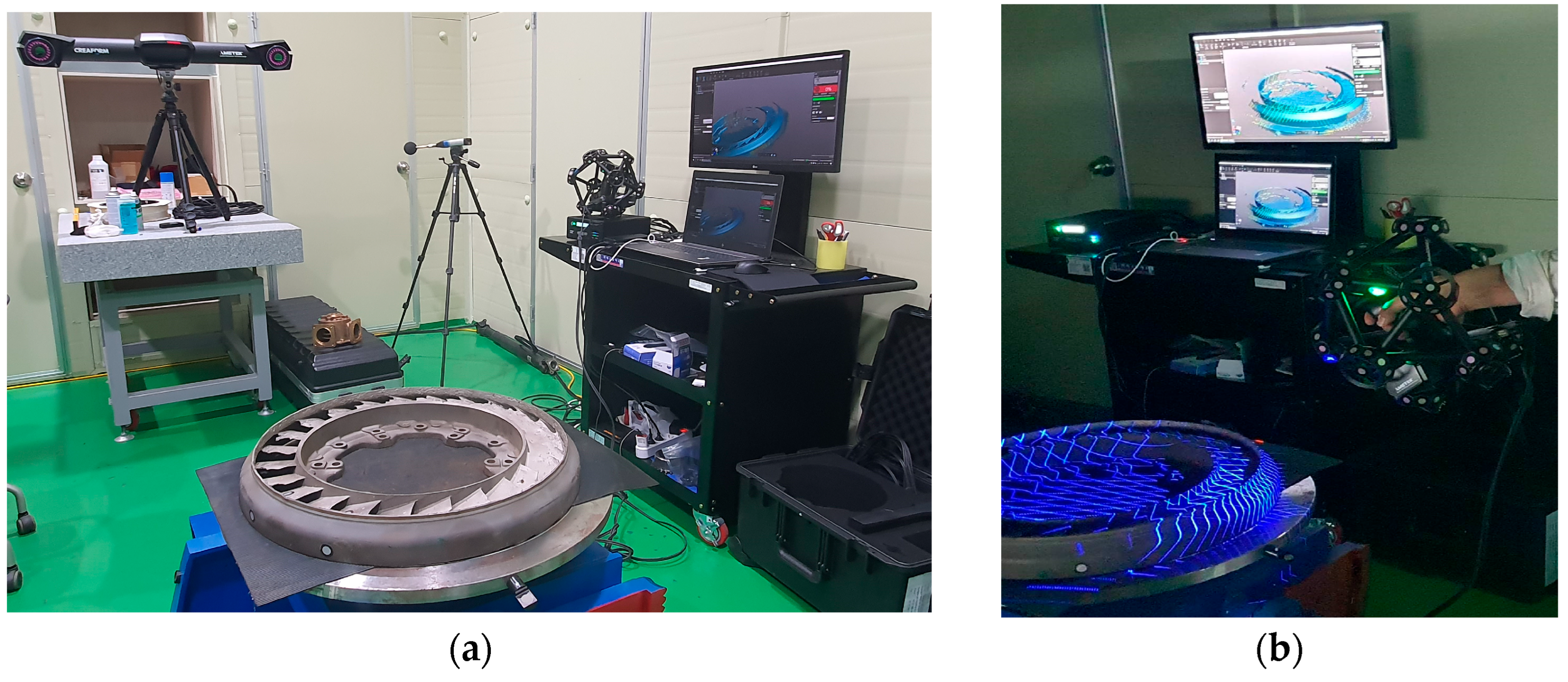
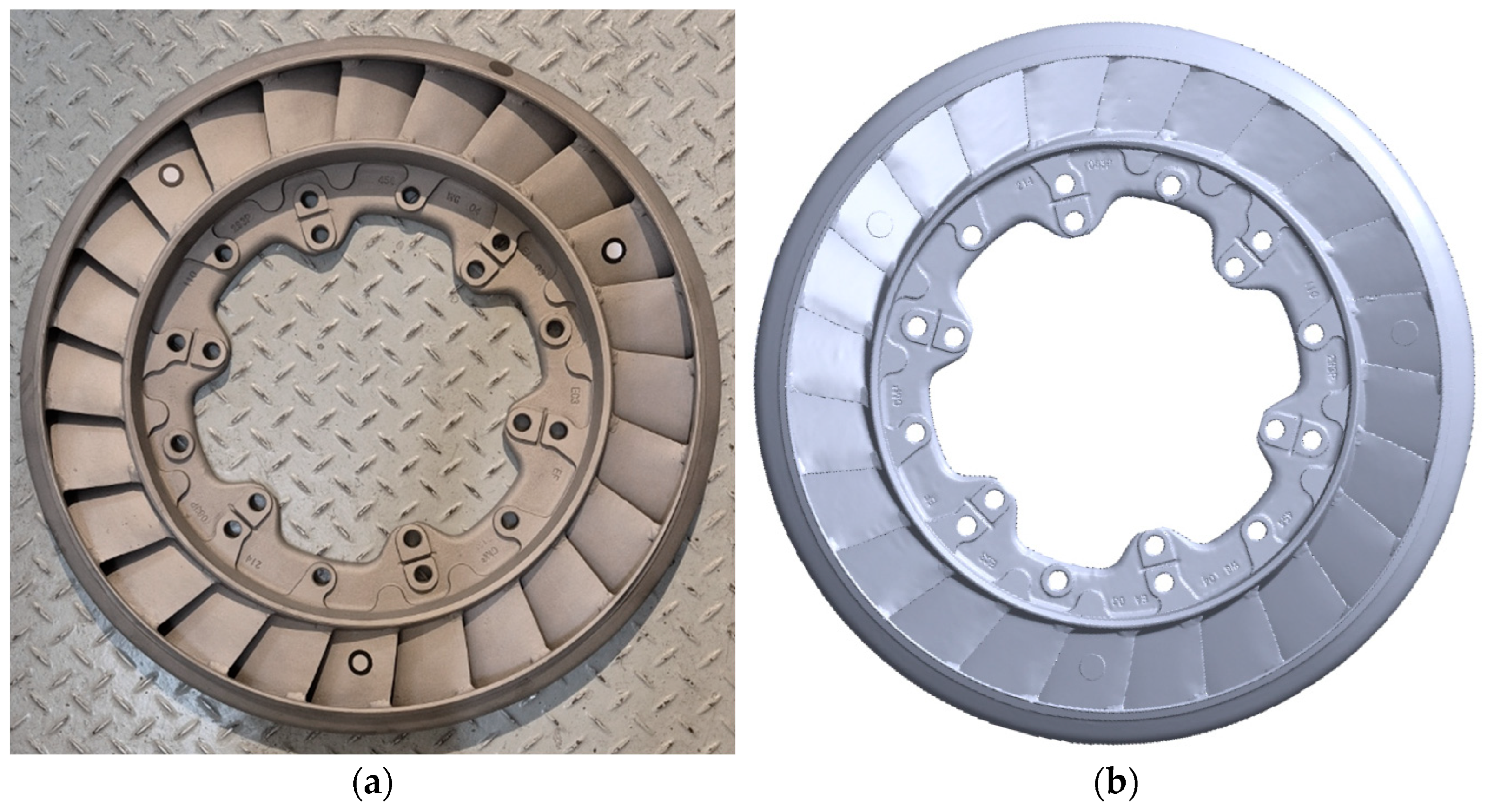
2.3. Reverse Engineering for Nozzle Ring
2.4. Numerical Methods
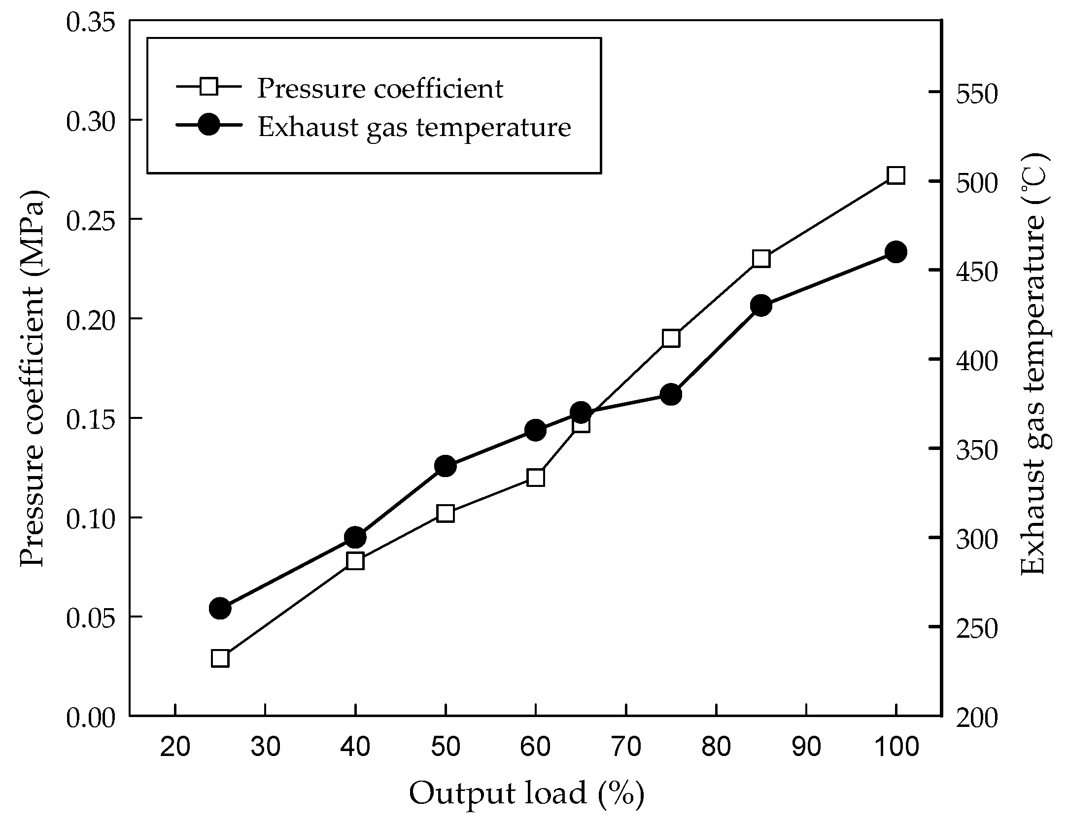
2.5. Field Performance Test
3. Results and Discussion
3.1. Reverse Engineering
3.2. Numerical Analysis
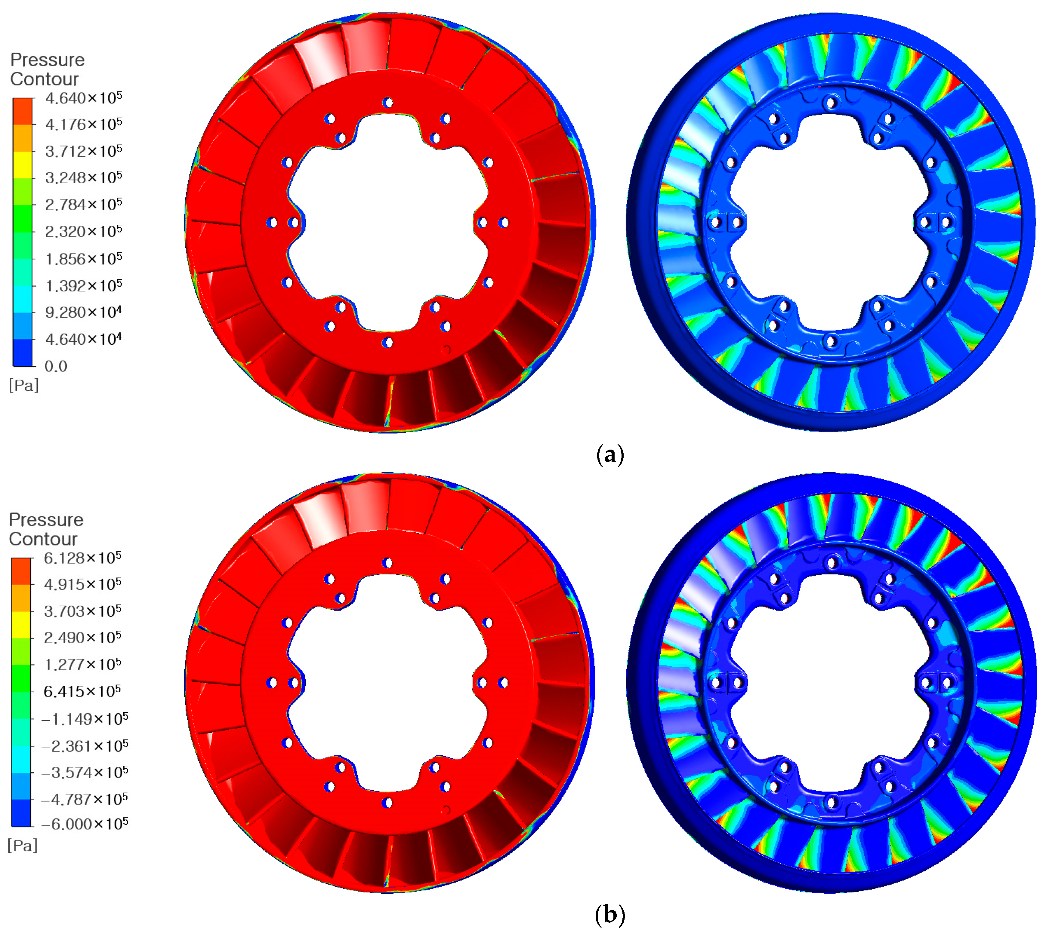
3.2.1. Load Distribution
3.2.2. Stress-Life Fatigue Analysis
3.3. Field Performance Test
4. Conclusions
- (1)
- A 3D scanner was used to develop a numerical model for the nozzle ring of the turbocharger with complex geometry. Since the performance of the nozzle ring is determined by the geometric characteristics of the blade and flow path, an optics tracker was used to acquire geometric data, which formed the basis for accurate analysis in the numerical study. A numerical model was derived accordingly.
- (2)
- For the analysis and assessment of the structural safety of the nozzle ring reproduced through reverse engineering, the surface pressure coefficient and exhaust gas temperature for each output load were set as boundary conditions in the finite element model of the nozzle ring. The numerical modeling confirmed exposure to higher exhaust gas temperatures and pressures for the aged main engine to achieve its original performance. Static structural analysis, with the surface pressure coefficient and exhaust gas temperature set as boundary conditions, resulted in a maximum blade deflection of 0.47 mm, and a sharp increase in the maximum equivalent stress and strain was observed at output loads of 85% or above.
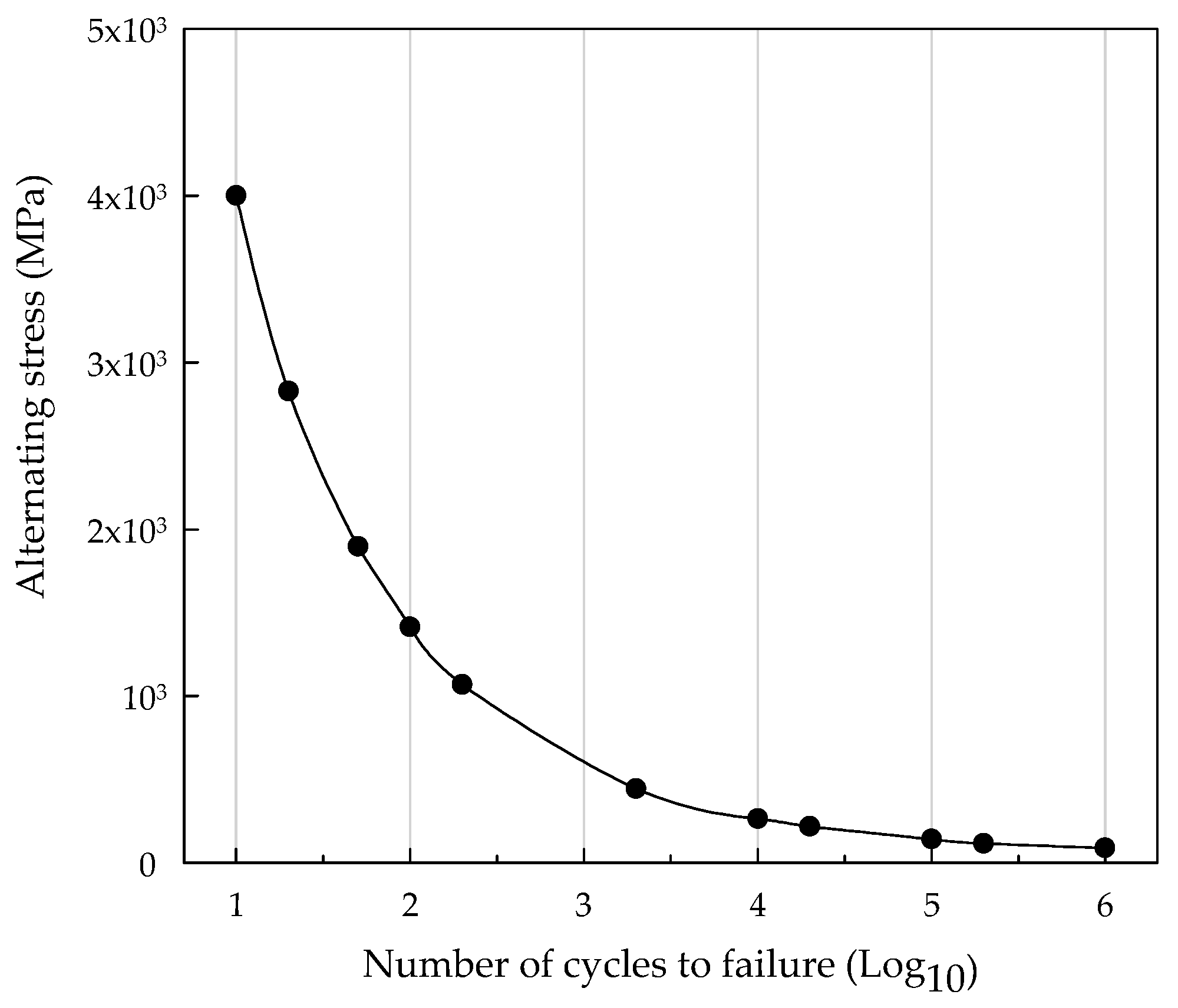
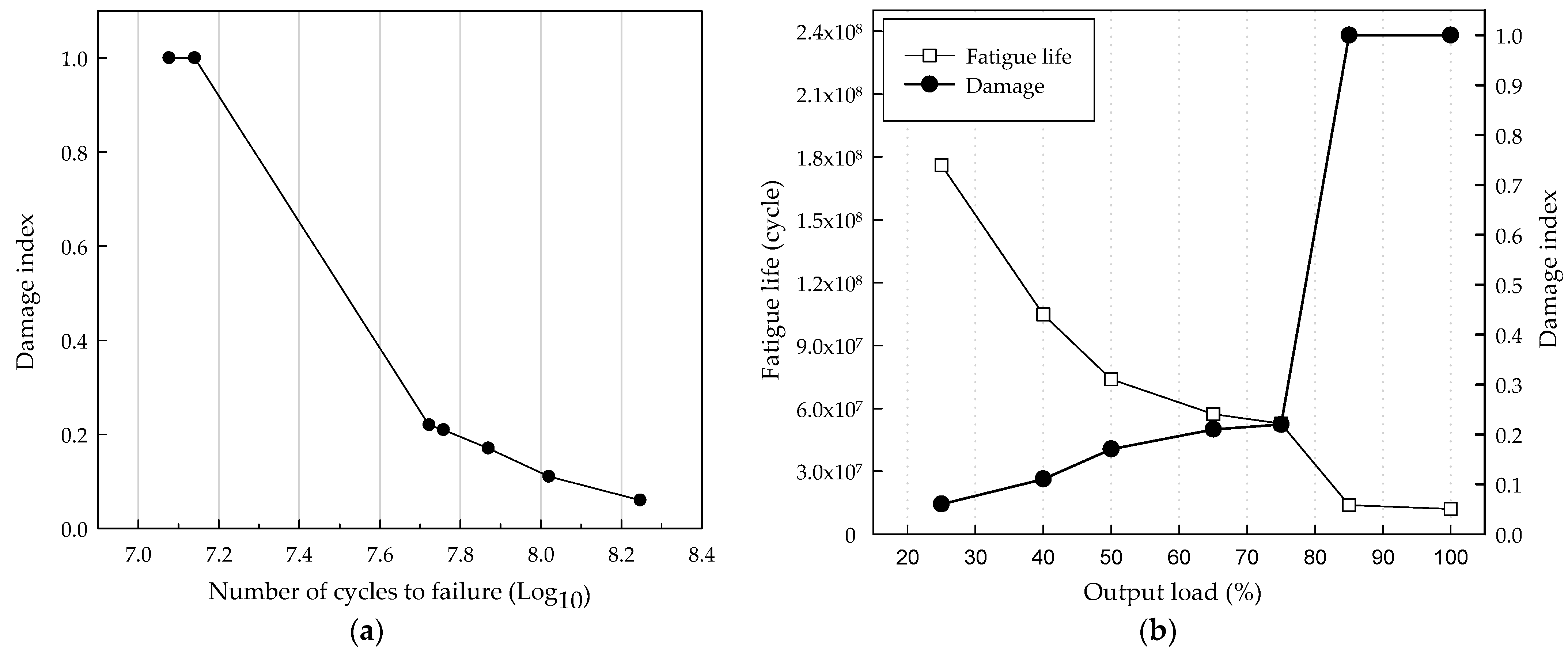
- (3)
- The stress-life fatigue analysis of the nozzle ring was performed based on the S-N curves and the high cycle fatigue theory, considering the operating characteristics of the ship, with a cycle set as the cut-off in the analysis. The fatigue life derived from the stress-life fatigue analysis showed a maximum of cycles at 25% output load, while the damage index was at 100% output load, showing conflicting trends.
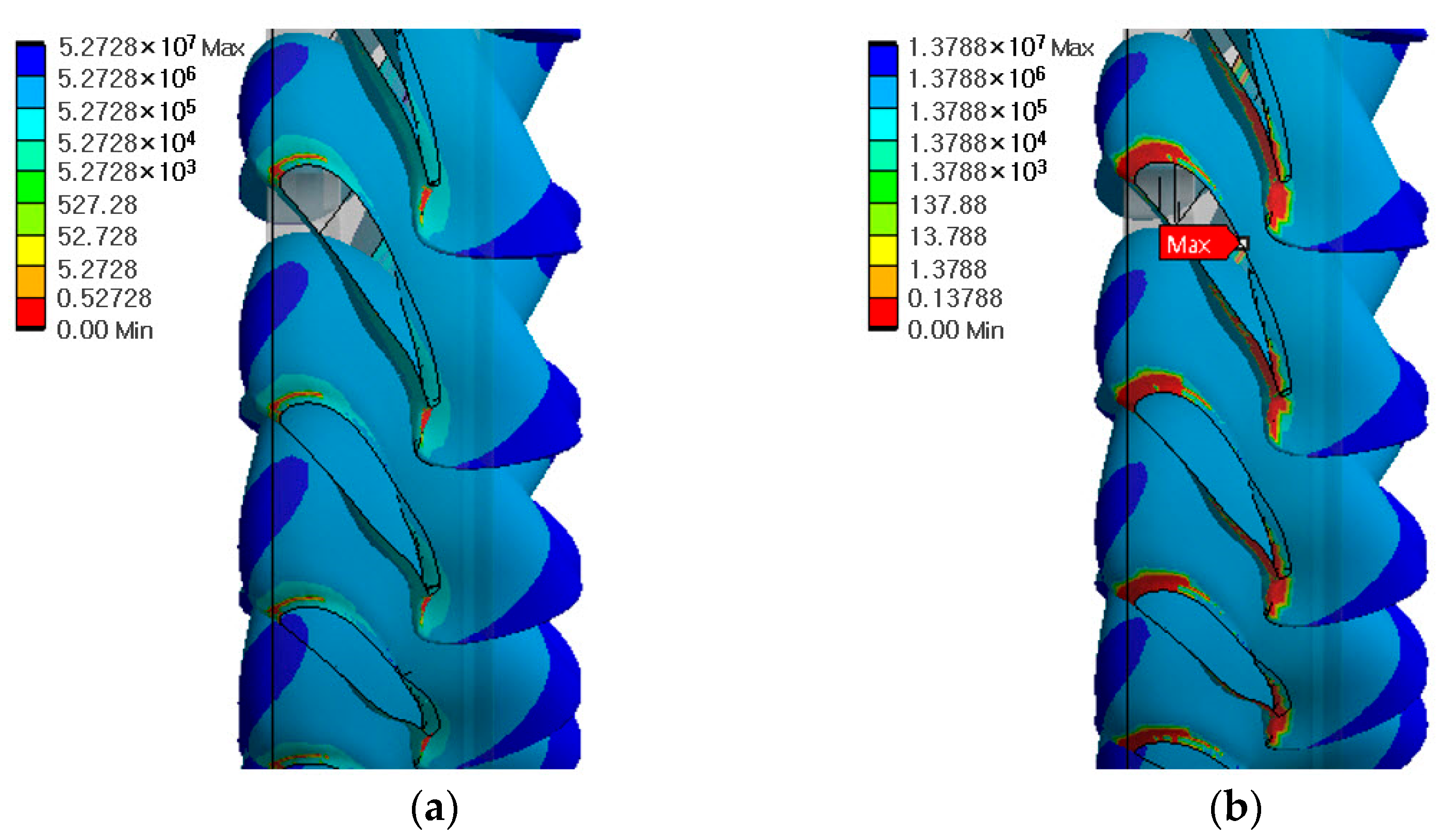
- (4)
- The fatigue life and damage of the nozzle ring blade exhibited locally different characteristics between the leading edge and trailing edge. At 85% output load, the fatigue life was high in the middle area between the leading and trailing edges, but at the edge area near the outer hoop, the fatigue life was close to ‘0’. This is reasoned to be attributable to the concentration of damage in the area, as the high internal stress of the blade was repeatedly applied, as derived from the static structural analysis. Additionally, the damage index of the nozzle ring was small throughout the leading edge and trailing edge areas, except for the edge area of the blade.
- (5)
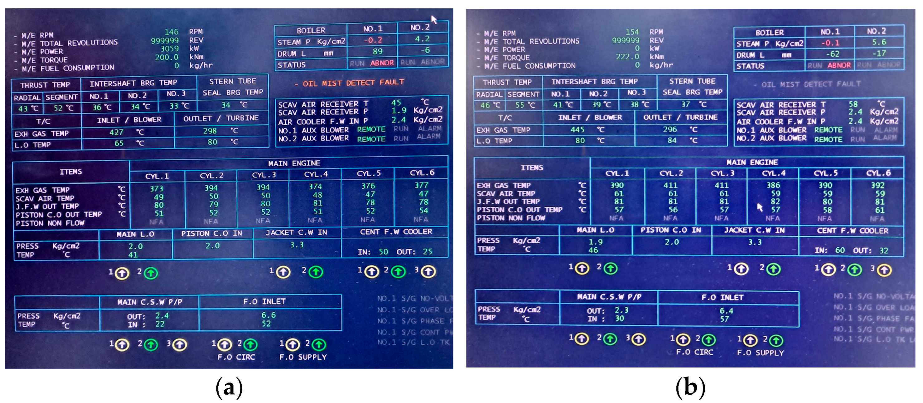
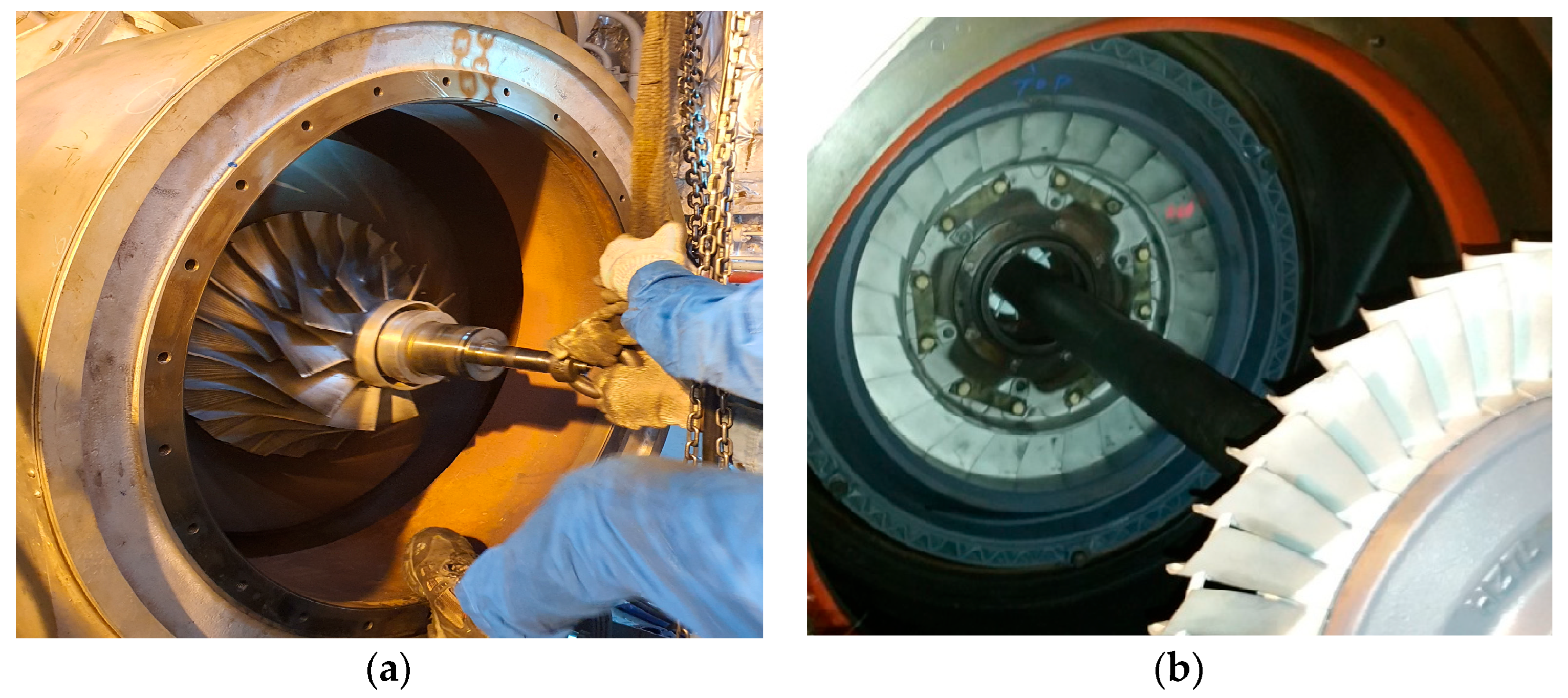
- A field performance test of the main engine was conducted to evaluate the validity of the numerical analysis results under the operating conditions of output load 75% and output load 85%, the latter corresponding to an indicated cylinder exhaust gas temperature exceeding 400 °C. At 85% output load, severe damage occurred in the nozzle ring blade, and propagation of the fatigue crack in the area where the outer hoop and the tip of the blade trailing edge were in contact, extending toward the leading edge, was confirmed. The area of damage observed in the field performance test and the area of maximum damage index from the stress-life fatigue analysis were highly similar, verifying the validity of the numerical analysis in this study.
Author Contributions
Funding
Data Availability Statement
Conflicts of Interest
Nomenclature
| T/C | Turbocharger | b | Fatigue strength exponent |
| Nitrogen oxides | D | Total damage | |
| SOx | Sulfur oxides | Number of stress cycles | |
| ECA | Emission Control Areas | MPa | Mega pascal |
| VTR | Vane-flow test rig | IMO | International Maritime Organization |
| SST | Shear stress transport | MCR | Maximum continuous rating |
| Stress range | CFD | Computational fluid dynamics | |
| Stress amplitude | Mean of the maximum and minimum stress | ||
| Reversals to failure | S-N | Stress-number of cycles to failure | |
| Fatigue strength coefficient |
References
- Review of Maritime Transport 2024. United Nations Conference on Trade and Development. Available online: https://unctad.org/publication/review-maritime-transport-2024 (accessed on 7 April 2025).
- Lee, Y.J.; Choi, J.; Cho, K. Experimental Study on Reduction of Emissions for Marine Diesel Engines with a Double Post Injection. J. Korean Soc. Mar. Eng. 2015, 39, 418–424. [Google Scholar]
- Fourth Greenhouse Gas Study 2020. International Maritime Organization. Available online: https://www.imo.org/en/OurWork/Environment/Pages/Fourth-IMO-Greenhouse-Gas-Study-2020.aspx (accessed on 7 April 2025).
- Anantharaman, M.; Islam, R.; Sardar, A.; Garaniya, V.; Khan, F. Impact of Defective Turbocharging System on the Safety and Reliability of Large Marine Diesel Engine. Int. J. Mar. Navig. Saf. Sea Transp. 2021, 15, 189–194. [Google Scholar] [CrossRef]
- Chybowski, L.; Jakubowski, A.; Żółkiewski, S. Analysis of the Relationship between Selected Ship and Propulsion System Characteristics and the Risk of Main Engine Turbocharger Explosion. J. Mar. Sci. Eng. 2023, 11, 360. [Google Scholar] [CrossRef]
- European Maritime Safety Agency, Annual Overview of Marine Casualties and Incidents 2024. Available online: https://www.emsa.europa.eu/publications/item/5352-annual-overview-of-marine-casualties-and-incidents-2024.html (accessed on 7 April 2025).
- Marine Accident Statistics Report 2023, Korea Maritime Safety Tribunal. Available online: https://www.kmst.go.kr/web/board.do?menuIdx=135 (accessed on 7 April 2025).
- Vizentin, G.; Vukelic, G.; Murawski, L.; Recho, N. Marine Propulsion System Failures—A Review. J. Mar. Sci. Eng. 2020, 8, 662. [Google Scholar] [CrossRef]
- Andersson, N.; Kisbenedek, E. Review on Recent Advances for Marine Turbocharger Technologies for Two-Stroke Diesel Engines. Bachelor’s Thesis, Chalmers University of Technology, Gothenburg, Sweden, 2018. [Google Scholar]
- Lus, T. Marine diesel engines turbochargers diagnostic methods. Appl. Struct. Health Usage Cond. Monit. 2012, 3, 49–54. [Google Scholar]
- Borovkov, A.; Voinov, I.; Galerkin, Y.; Kaminsky, R.; Drozdov, A.; Solovyeva, O.; Soldatova, K. Design, Plant Test and CFD Calculation of a Turbocharger for a Low-Speed Engine. Appl. Sci. 2020, 10, 8344. [Google Scholar] [CrossRef]
- Hoffren, J.; Talonpoika, T.; Larjola, J.; Siikonen, T. Numerical Simulation of Real-Gas Flow in a Supersonic Turbine Nozzle Ring. J. Eng. Gas Turbines Power 2002, 124, 395–403. [Google Scholar] [CrossRef]
- Serrano, J.R.; Tiseira, A.O.; Lopez-Carrillo, J.A.; Hervas-Gomez, N. Numerical Evaluation in a Scaled Rotor-Less Nozzle Vaned Radial Turbine Model under Variable Geometry Conditions. Appl. Sci. 2022, 12, 7254. [Google Scholar] [CrossRef]
- Jeong, H.; Yang, C. Structural Design Optimization of Tidal Current Turbine Blades Based on Structural Safety Factors. IEEE Access 2024, 12, 193028. [Google Scholar] [CrossRef]
- Kneževic, V.; Orovic, J.; Stazic, L.; Culin, J. Fault Tree Analysis and Failure Diagnosis of Marine Diesel Engine Turbocharger System. J. Mar. Sci. Eng. 2020, 8, 1004. [Google Scholar] [CrossRef]
- Galindo, J.; Fajcrdo, P.; Navarro, R.; Gracia-Cuevas, L.M. Characterization of a radial turbocharger turbine in pulsating flow by means of CFD and its application to engine modeling. Appl. Energy 2013, 103, 116–127. [Google Scholar] [CrossRef]
- Shen, H.; Tang, F.; Jiang, D.; Lu, D.; Jia, B.; Liu, Q.; Zhang, X. Parametric Investigation on the Influence of Turbocharger Performance Decay on the Performance and Emission Characteristics of a Marine Large Two-Stroke Dual Fuel Engine. J. Mar. Sci. Eng. 2024, 12, 1298. [Google Scholar] [CrossRef]
- Choi, I.; Kim, H.K.; Yoo, B.W. An Analytical Study on the Turbocharger Engine Matching of the Marine Four-Stroke Diesel Engine. In Proceedings of the Korean Society of Marine Engineering Fall Conference 2005, Busan, Republic of Korea, 1 November 2005. [Google Scholar]
- Witek, L.; Stachowicz, F. Modal Analysis of the Turbine Blade at Complex Thermomechanical Loads. Strength Mater. 2016, 48, 474–480. [Google Scholar] [CrossRef]
- Lee, C. A study on power improvement emission characteristics of marine diesel engine with response power 220HP turbocharger. J. Korean Soc. Mar. Eng. 2013, 37, 911–917. [Google Scholar]
- Altosole, M.; Balsamo, F.; Campora, U.; Mocerino, L. Marine Dual-Fuel Engines Power Smart Management by Hybrid Turbocharging Systems. J. Mar. Sci. Eng. 2021, 9, 663. [Google Scholar] [CrossRef]
- Mizythras, P.; Boulougouris, E.; Theotokatos, G. A novel objective oriented methodology for marine engine–turbocharger matching. Int. J. Engine Res. 2021, 23, 2105–2127. [Google Scholar] [CrossRef]
- Lee, K.H. Analysis of Horizontal Axis Tidal Turbine Performance and Turbine Efficiency Deficit from Blade Deformation. Ph.D. Thesis, Inha University, Incheon, Republic of Korea, 2016. [Google Scholar]
- Jeong, H.; Yang, C. Variation in Flow Characteristics and Power Performance Due to Axial Distance Optimization in the Design of Counter-Rotating Tidal Turbines. Energies 2024, 17, 3207. [Google Scholar] [CrossRef]
- Martini, F.; Ibrahim, H.; Montoya, L.T.C.; Rizk, P. Turbulence Modeling of Iced Wind Turbine Airfoils. Energies 2022, 15, 8325. [Google Scholar] [CrossRef]
- Bahaj, A.S.; Molland, A.F.; Chaplin, J.R.; Batten, W.M.J. Power and thrust measurements of marine current turbines under various hydrodynamic flow conditions in a cavitation tunnel and a towing tank. Renew. Energy 2007, 32, 407–426. [Google Scholar] [CrossRef]
- Wang, J.; Wang, R.; Zhang, R.; Lu, Y.; Wang, D.; Fu, Q. Prediction of stress-fatigue life on the impeller of the reactor coolant pump based on fluid-thermal-structure interaction method. Ann. Nucl. Energy 2023, 193, 110029. [Google Scholar] [CrossRef]
- Corti, E.; Raggini, L.; Rossi, A.; Brusa, A.; Moro, D. Investigation of aging effects on combustion and performance characteristics of mining engines. SAE Int. J. Engines 2023, 16, 515–527. [Google Scholar] [CrossRef]
- Fu, Q.; Wang, D.; Zhang, R.; Lu, Y.; Wang, R. Stress analysis and stress fatigue life prediction of RCP impeller based on fluid-thermal-solid coupling. Nucl. Eng. Des. 2023, 414, 112596. [Google Scholar] [CrossRef]


| Description | Value |
|---|---|
| Model | HYUNDAI B&W 6S35MC Mk7 |
| Number of cylinders | 6 |
| Cylinder bore | 350 mm |
| Stroke | 1400 mm |
| Output | 6060 bhp |
| Revolution | 173 rpm |
| Description | Value |
|---|---|
| Model | VTR454 |
| Max. rpm | 18,420 |
| Max. temperature | 590 °C |
| Weight | 3400 kg |
| Property | Value |
|---|---|
| Specific heat | 0.5 (J/g°C) |
| Specific gravity | 7.93 |
| Coefficient of thermal expansion | 17.3 W/m∙°C |
| Thermal conductivity | 16.3 W/m∙°C |
| Yield strength | ≥175 N/mm2 |
| Tensile strength | ≥480 N/mm2 |
| Elongation | ≥40% |
| Description | Value |
|---|---|
| Accuracy | 0.025 mm |
| Volumetric accuracy | 16.6 m3 (0.078 mm) |
| Measurement resolution | 0.025 mm |
| Measurement rate | 1,800,000 measurement/s |
| Light source | 15 blue laser crosses |
| Scanning area | 310 × 350 mm |
| Stand-off distance | 300 mm |
| Depth of field | 250 mm |
| Load (%) | RPM | ||
|---|---|---|---|
| Turbocharger | Main Engine | ||
| Sea-trial (2003) | 75 | 15,100 | 157.2 |
| 85 | 16,100 | 163.9 | |
| Sailing (2024) | 75 | 14,300 | 147.0 |
| 85 | 15,400 | 155.4 | |
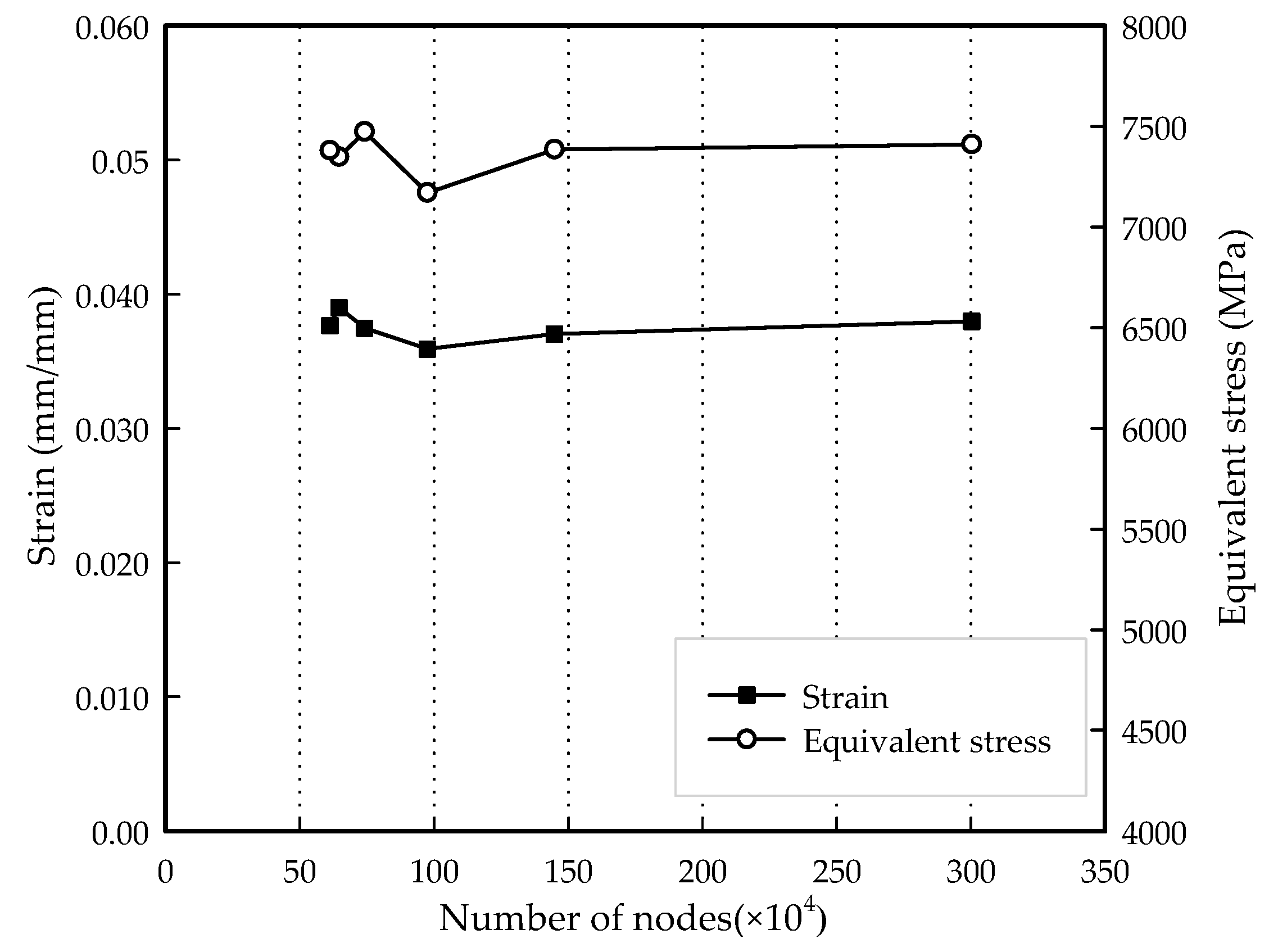
| Mesh Size (mm) | Nodes | Elements |
|---|---|---|
| 1 | 3,002,917 | 2,453,090 |
| 2 | 1,448,491 | 883,708 |
| 3 | 974,867 | 595,281 |
| 5 | 740,385 | 454,335 |
| 7 | 646,045 | 395,331 |
| 10 | 611,681 | 374,871 |
Disclaimer/Publisher’s Note: The statements, opinions and data contained in all publications are solely those of the individual author(s) and contributor(s) and not of MDPI and/or the editor(s). MDPI and/or the editor(s) disclaim responsibility for any injury to people or property resulting from any ideas, methods, instructions or products referred to in the content. |
© 2025 by the authors. Licensee MDPI, Basel, Switzerland. This article is an open access article distributed under the terms and conditions of the Creative Commons Attribution (CC BY) license (https://creativecommons.org/licenses/by/4.0/).
Share and Cite
Jeon, W.-S.; Jeong, H. Structural Safety Assessment Based on Stress-Life Fatigue Analysis for T/C Nozzle Ring Blade. J. Mar. Sci. Eng. 2025, 13, 1174. https://doi.org/10.3390/jmse13061174
Jeon W-S, Jeong H. Structural Safety Assessment Based on Stress-Life Fatigue Analysis for T/C Nozzle Ring Blade. Journal of Marine Science and Engineering. 2025; 13(6):1174. https://doi.org/10.3390/jmse13061174
Chicago/Turabian StyleJeon, Woo-Seok, and Haechang Jeong. 2025. "Structural Safety Assessment Based on Stress-Life Fatigue Analysis for T/C Nozzle Ring Blade" Journal of Marine Science and Engineering 13, no. 6: 1174. https://doi.org/10.3390/jmse13061174
APA StyleJeon, W.-S., & Jeong, H. (2025). Structural Safety Assessment Based on Stress-Life Fatigue Analysis for T/C Nozzle Ring Blade. Journal of Marine Science and Engineering, 13(6), 1174. https://doi.org/10.3390/jmse13061174