Article

Monocular Unmanned Boat Ranging System Based on YOLOv11-Pose Critical Point Detection and Camera Geometry

1
Institute of Logistics Science and Engineering, Shanghai Maritime University, Shanghai 201306, China
2
SPG Qingdao Port Group Co., Ltd., Qingdao 266011, China
3
Merchant Marine College, Shanghai Maritime University, Shanghai 201306, China
4
Chongqing Key Laboratory of Green Logistics Intelligent Technology, Chongqing Jiaotong University, Chongqing 400074, China
5
College of Marine Science and Engineering, Shanghai Maritime University, Shanghai 201306, China
6
Shanghai Ship and Shipping Research Institute Co., Ltd., Shanghai 201306, China
7
Instituto de Telecomunicações (IT), North Tower, 10th Floor, Av. Rovisco Pais 1, 1049-001 Lisbon, Portugal
8
Department of Information Science and Technology, Iscte—Instituto Universitário de Lisboa, Av. das Forças Armadas, 1649-026 Lisbon, Portugal
*
Author to whom correspondence should be addressed.
J. Mar. Sci. Eng. 2025, 13(6), 1172; https://doi.org/10.3390/jmse13061172
Submission received: 28 April 2025 / Revised: 10 June 2025 / Accepted: 13 June 2025 / Published: 14 June 2025
(This article belongs to the Section Ocean Engineering)

Abstract

Unmanned boat distance detection is an important foundation for autonomous navigation tasks of unmanned boats. Monocular vision ranging has the advantages of low hardware equipment requirements, simple deployment, and high efficiency of distance detection. Unmanned boats can sense the real-time navigational situation of waters through monocular vision ranging, providing data support for their autonomous navigation. This paper establishes a framework for unmanned boat distance detection. The framework extracts and recognizes the features of an unmanned boat through Yolov11m-pose and selects the key points of the ship for physical distance mapping. Using the camera calibration to obtain the pixel focal length, the main point coordinates and other parameters are obtained. The number of pixel points in the image key point to the image center pixel and the actual distance of the camera from the horizontal plane are combined with the focal length of the camera for triangular similarity conversion. These data are fused with the camera pitch angle and other parameters to obtain the final distance. At the same time, experimental verification of the key point detection model demonstrates that it fully meets the requirements for unmanned boat ranging tasks, as assessed by Precision, Recall, mAP50, mAP50-95 and other indicators. These indicators show that Yolov11m-pose has a better accuracy in the key point detection task with an unmanned boat. The verification experiments also illustrate the accuracy of the key point-based physical distance mapping compared with the traditional detection frame-based physical distance mapping, which was assessed by the mean squared error (MSE), the root mean square error (RMSE), and the mean absolute error (MAE). The metrics show that key point-based unmanned boat distance mapping has greater accuracy in a variety of environmental situations, which verifies the effectiveness of this approach.

1. Introduction

As an important tool in maritime patrol, maritime search and rescue and other tasks [1,2,3], unmanned boats have the advantages of agile action, low cost, easy operation, etc. [4], and navigational situational awareness has a pivotal role in the autonomous navigation technology of unmanned boats [5,6,7,8]. With the development of neural network technology, maritime unmanned boat autonomous sensing technology has become the current research hotspot [9,10,11]. Traditional unmanned boat ranging methods include laser ranging, radar ranging, and self-organized network ranging methods [12,13,14,15,16].
Binocular ranging methods have the disadvantages of difficult camera arrangement and slow image-matching algorithms [17,18,19]. Wei et al. greatly accelerated the image-matching speed of binocular camera ranging by improved multi-target stereo matching algorithms, which accelerated the speed of ranging and added focus loss to compensate for the imbalance of high- and low-quality samples in the gradient [20].
Distance measurement based on monocular vision as a means of active cognition of the navigational posture of unmanned boats has the advantages of low cost and fast perception, and monocular ranging was first applied in the field of unmanned perception of vehicles and autonomous cruising of unmanned aerial vehicles. In order to ensure the safety of autonomous navigation of the surrounding vehicles, monocular ranging is also widely used to detect the distance of the surrounding vehicles. Lv et al. realized a distance detection task based on YOLOv5-RedeCa detector, Bot-Sort tracker and abnormal jump change filter, solved the distance detection error problem caused by the jump change in the size of the detection frame in the process of ranging, and improved the stability of the distance detection [21]. Li et al. designed a novel architecture for all-weather distance monitoring based on monocular vision D-LDRNet. The framework combines the monocular ranging principle with a priori radar knowledge to realize the actual distance detection, and at the same time, introduces a low-light enhancement network to improve the robustness of the physical distance detection task at night time [22]. Liu et al. improved the monocular ranging principle, and with the help of the road voxel point, achieved a camera pose estimation, improving the distance estimation framework’s ranging ability in the case of camera jitter through the camera pose parameter [23]. Li et al. proposed a MonoDepth2-based ranging algorithm to address the problems of large error, blurred image generation and loss of details in the distance detection task; their algorithm improves the network’s ability for feature fusion in different scales of the scene and is able to better extract the target features, thus improving the physical distance mapping ability [24]. Li et al. proposed a monocular visual detection model DID-CAYOLO, which improves the ranging network’s ability to range key targets by enhancing the YOLOv7 network to improve the network’s focus on key regions in the image through the CA attention mechanism and uses the inverse transmittance algorithm to obtain the target distance [25]. Wang et al. creatively used the Kalman filter algorithm to fuse monocular and binocular ranging to cope with complex ranging environments. The framework uses AUKF to dynamically fuse monocular and binocular ranging, introduces an adaptive noise-adjustment mechanism to dynamically update the observation noise according to the fusion residuals, and suppresses outlier interference to improve the stability of the ranging task in complex situations [26]. Monocular ranging is also widely used in robotic ranging tasks. Jing et al. combined yolov8 with the monocular ranging model to accomplish the robot’s target perception task, and the method greatly improved the robustness of target distance detection by establishing a visual distance error compensation model to correct the estimation results of the monocular ranging model [27]. Qi et al. realized the target key point detection and localization task in a USV formation mission based on Yolov8-pose and the PnP ranging principle, which balanced the accuracy of ranging as well as the speed of ranging to achieve a balance of efficiency and accuracy [28].
Meanwhile, multi-source information fusion ranging has also been a research hotspot in recent years [29,30]. Li et al. combined a priori radar knowledge with monocular vision ranging framework for vehicle ranging and monitoring with good robustness [22]. Liu et al. combined laser ranging with monocular ranging to realize task of target localization, building a laser vision system to track and capture an aircraft image and object distances and utilizing estimated 6D attitude parameters and aircraft 3D positional parameters to achieve the target localization task. They used 6D attitude parameters and a 3D model of the aircraft to render a dense 3D coordinate map of the aircraft and locate its exact position [13]. However, multi-source information fusion for target localization often requires complex hardware configuration techniques which are difficult to realize. In the field of unmanned boat ranging, Wang et al. designed a monocular ORB-SLAM framework based on the characteristics of the marine environment. The framework extracts image features to detect marine targets through Yolov5 and combines them with GNSS information to complete the task of map reconstruction. It then adopts a beam-ranging method to measure the target distance. The study achieved better results by autonomously collecting data from marine unmanned platforms [31]. In another study, an unmanned ship localization method based on Mask-RCNN was used to detect and segment the target ship to obtain its pixel shadow in the image. This was combined with the monocular ranging method based on ground constraints to realize the physical distance mapping of the unmanned ship. Experiments were then conducted on the CoppeliaSim simulation platform, which achieved better results theoretically, but the method has not been validated with realistic datasets and lacks realism [32].
In this paper, the Yolov11-pose key point detection framework is used to detect the key points of unmanned boats, and the key point of the unmanned boat closest to the water surface is selected as the physical mapping point, based on which, the real physical coordinates are mapped with the help of the geometric projection principle. The experimental data show that a physical distance mapping method based on key points of the ship has better robustness than one based on the detection frame.

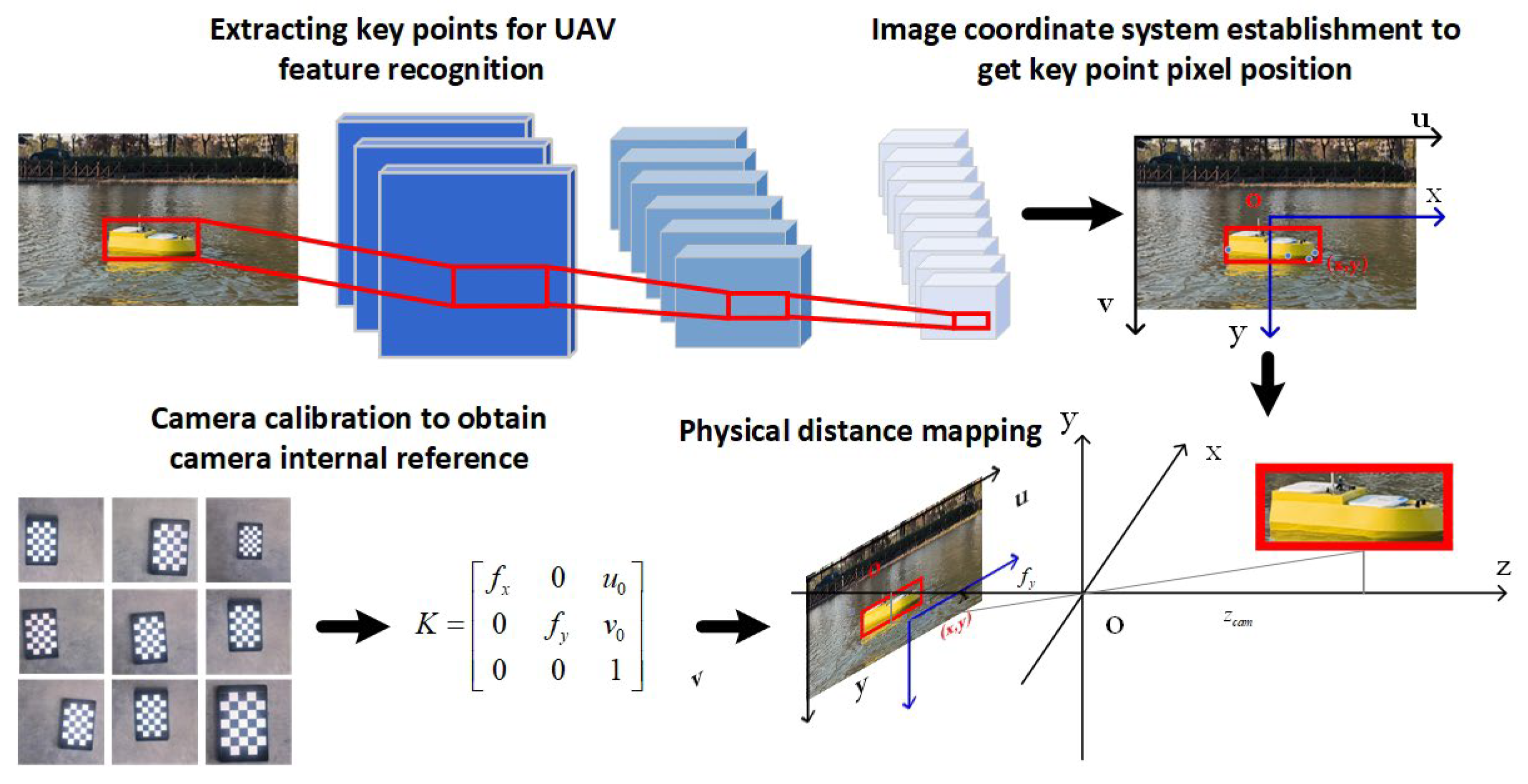
2. Ranging Principle

2.1. Ranging Model Framework

The unmanned boat distance measurement framework used in this paper mainly consists of an unmanned boat key point detection model and a physical distance mapping model. The yolov11x-pose is used as the USV key point detection module, which is mainly used to identify and detect the key points of the USV, select the appropriate key point, obtain the pixel position of the key point in the image, and pass it into the physical distance mapping model for actual distance conversion and obtain the actual position of the USV. The physical distance mapping part adopts the principle of monocular ranging for the conversion, and the required data are the appropriate key point of the unmanned boat, as well as camera parameters such as the camera focal length and main point position. Finally, the key points of the unmanned boat recognized by key point detection are passed into the physical distance mapping model to obtain the actual position; the whole process is shown in Figure 1.

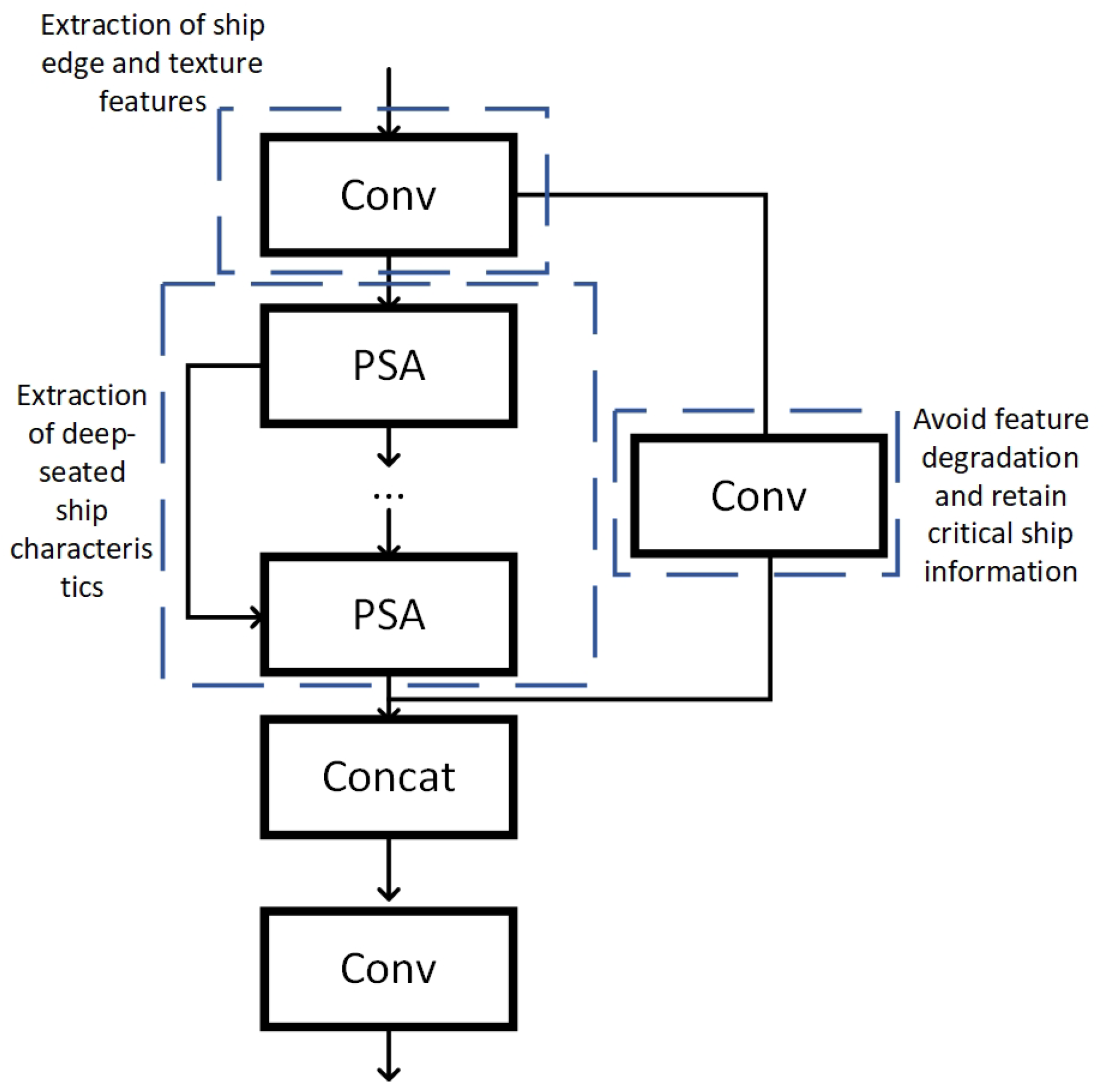
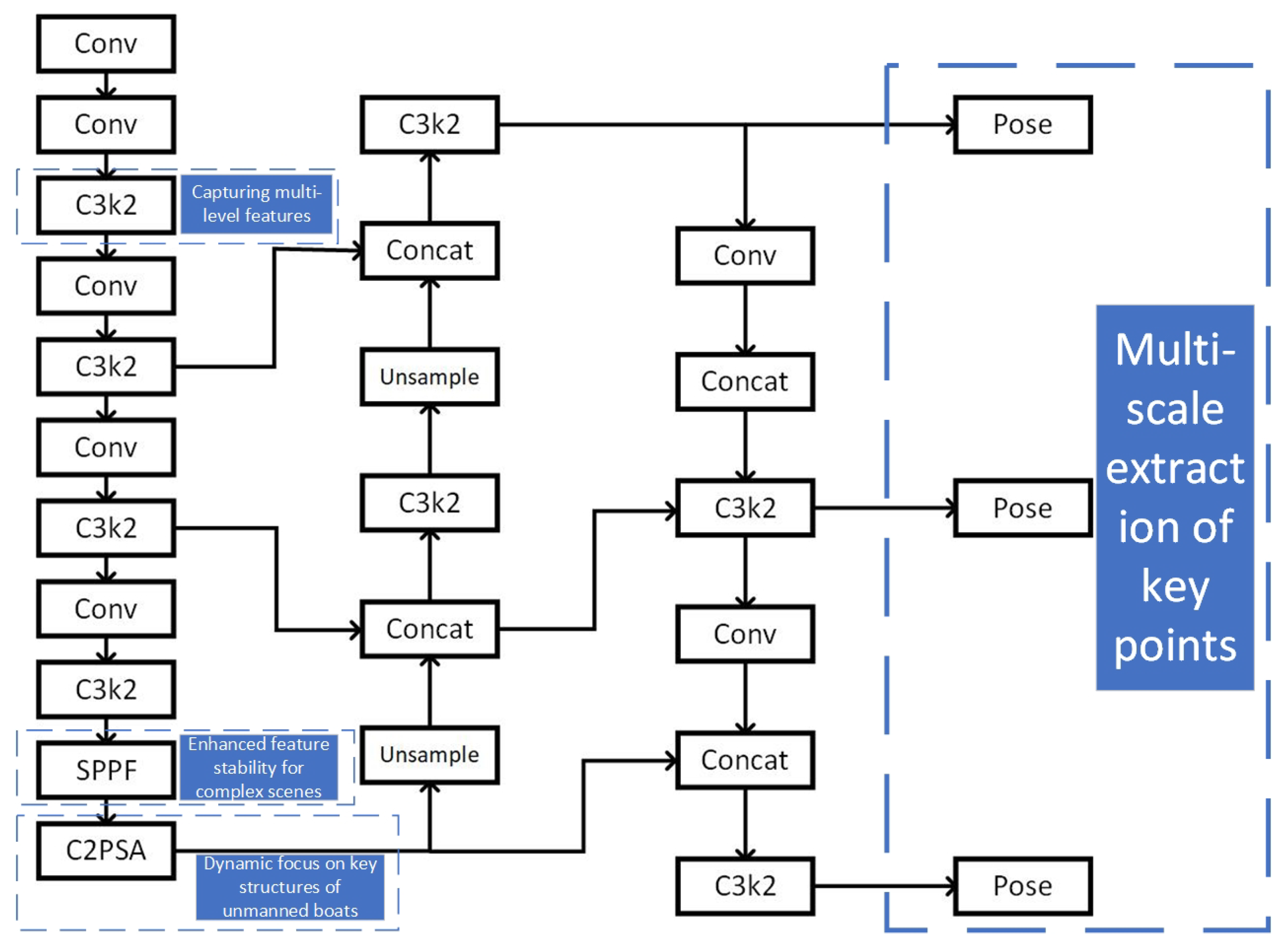
2.2. Critical Point Detection Model

Yolov11m-pose as a key point detection model is mainly used in the field of human posture detection, and also has better results in the field of unmanned boat key point detection. Compared to the previous generation version, Yolov11-pose has the added C3K2 mechanism, which realizes multi-channel feature fusion through two parallel convolutional operations, improving the speed of the network to extract the key features of the ship and ensuring the accuracy of the network while making efficient inference.
In addition, C2PSA is also an important module added to Yolov11-pose, which divides the feature map into two channels, one of which connects the feature map directly to the next layer, while the other channel connects the feature map to the lower layer of the network after processing by the PSA attention mechanism. This not only retains the original information of the feature map, but also dynamically adjusts the attention so that the network can reasonably distribute the attention to the various regions of the image and enhance the model’s ability to focus on key areas such as the ship and enhance its ability to reason about these key areas. By dynamically adjusting the attention, the network can reasonably allocate the attention to each region of the image, enhance the model’s attention to key features such as the contour of the unmanned boat, and improve the detection capability of the network in complex scenes. Moreover, the module improves the network’s ability to detect unmanned boats at different scales through multi-scale convolution and improves the distance extraction capability of the distance detection model for unmanned boats at different distances. The structure of the module is shown in Figure 2.
Yolov11-pose adopts a new network framework to better handle the key point extraction task of unmanned boats in complex navigation contexts. The whole network structure diagram of yolov11-pose is shown in Figure 3.

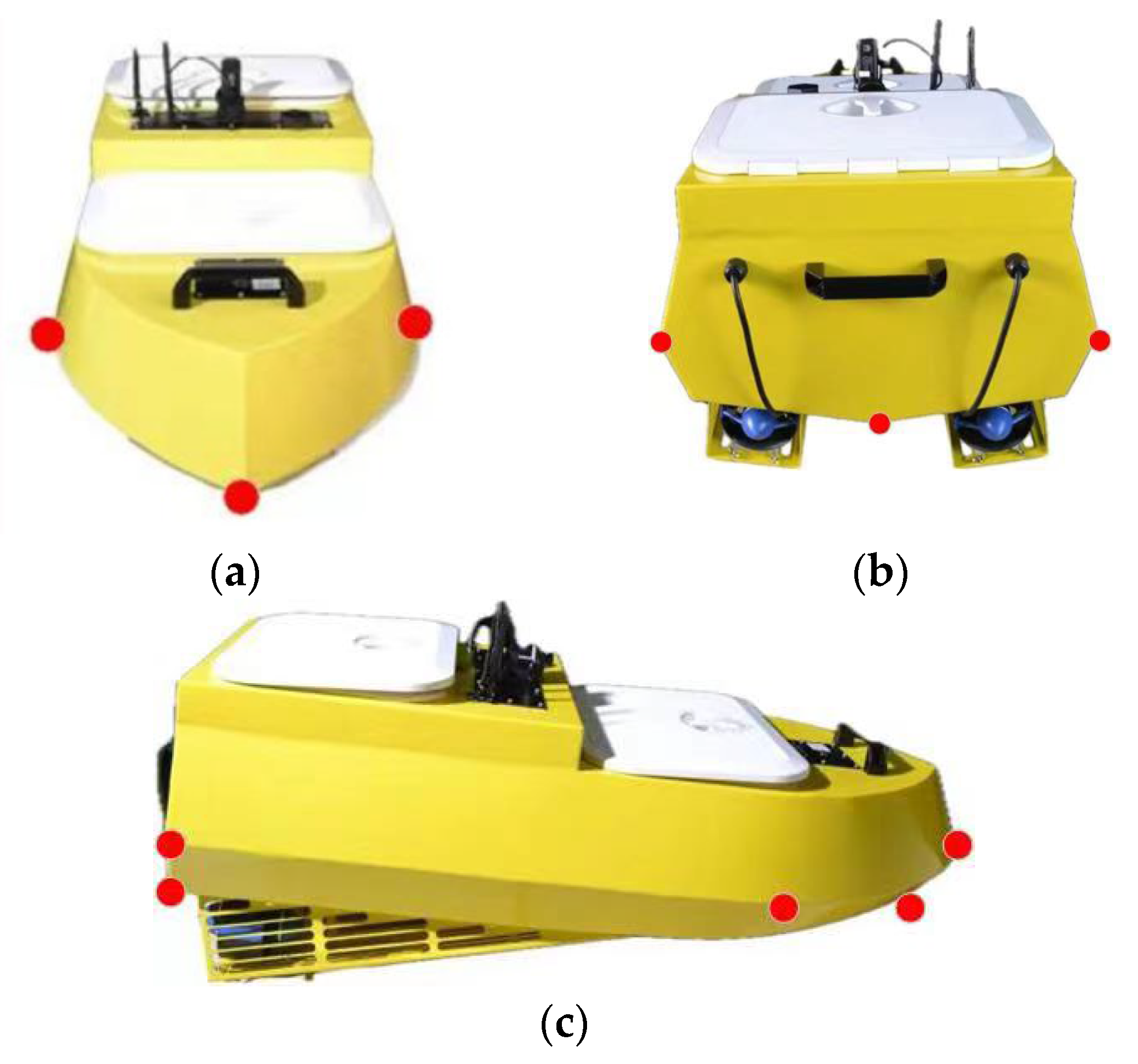
2.3. Key Point Selection

The experiment selects seven key points in the hull of the USV model as the target points of the key point detection model. The seven key points are located in the bow, the left side of the bow, the right side of the bow, the bottom of the bow, the left side of the stern, the right side of the stern and the bottom of the stern. These seven selected key points on the USV model can help the model to understand the physical structure of the USV. The model can better reflect the sailing angle of the USV, such as the attitude information. The two key points at the bottom are closer to the water surface and can be used as the conversion points for physical distance mapping to more accurately convert the actual distance of the USV. The distribution of the key points is shown in Figure 4.

3. Camera Internal Reference Calibration

Camera internal reference acquisition is a key step of the experiment, and obtaining accurate camera parameters is crucial to the accuracy of the physical distance mapping. This experiment uses Zhang’s camera calibration method to obtain the camera internal reference. The Zhang Zhengyou calibration method, also known as Zhang’s calibration method, is widely used in the field of machine vision for its simplicity and effectiveness [33]. This method is used to accurately obtain the internal reference and external reference of the camera, and can be effectively carried out in the camera. The material needed for this method is a fixed-size black-and-white checkerboard grid. The grid is photographed at different angles and calculated using a single-stress matrix to establish the mapping relationship between the 2D image points and the 3D calibration plate points. The specific formulae are as follows:
s u v 1 = H X Y 1 ,   H = K r 1 r 2 t
where u and v denote the pixel coordinates in the image coordinate system and represent the position of a 2D image point, s is the scale factor, H is the uni-responsive matrix, K is the desired camera internal reference matrix, r1 and r2 are the first two columns of the rotation matrix, and t is the translation variable.

4. Physical Distance Mapping Principle

The physical distance mapping model mainly relies on the projection transformation principle. The position of the pixel points in the two-dimensional plane in the image, combined with the camera internal parameter calculation, are used to obtain the three-dimensional world and the real physical distance. The physical distance mapping needs the camera internal parameter, which can be expressed as K:
K = f x 0 u 0 0 f y v 0 0 0 1
where f x and f y are the focal lengths of the x-axis and y-axis of the camera image, and u 0 and v 0 are the positions of the camera’s principal points, respectively.
In addition, the image coordinate system is a two-dimensional coordinate system established with the midpoint of the image as the coordinate origin, and the horizontal and vertical coordinates are the positions of the pixel points in the image. Note that the coordinates of the physical distance mapping points in the image coordinate system are as follows:
Q = x c e n t e r u 0 y p o s e v 0 1
where u0, v0 are the coordinates of the main point, xcenter is the x-axis coordinate position of the key point, and ypose is the y-axis coordinate position of the key point of the unmanned ship closest to the water surface. Q is the form of chi-square coordinates after translation.
The coordinates of an object in the real world are the coordinates of a coordinate system with the camera as the origin, and the matrix consisting of the target’s coordinates (xcam, ycam, zcam) in a three-digit coordinate system is denoted as P:
P = x c a m y c a m z c a m
The three parameters in the P matrix are the real world coordinate system, with the camera position as the origin coordinates and the target distance in the x-axis, y-axis and z-axis directions, respectively. The P matrix can be calculated by the projection mapping relationship, which is given in the following formula:
P = x c a m y c a m z c a m = z c a m K 1 Q = z c a m f x 0 0 0 f y 0 u 0 v 0 1 x c e n t e r u 0 y p o s e v 0 1
The calculation of depth z is the key to distance mapping, which is mainly based on the principle of similar triangles. This principle mainly relies on the conversion between the physical reference height in the real world and the pixel height and pixel focal length of the reference object in the image and in the experiment. The height of the camera from the water surface under the simulated sailing state is taken as the known reference height in the physical world, and the difference between the y-coordinate of the center point of the image and the key point of the physical distance mapping is calculated as the pixel height. The difference between the y-coordinate of the image center point and the key point of the physical distance mapping is calculated as the pixel height, and the actual distance is calculated by adding the camera parameters obtained through Zhang’s calibration method. The specific calculations are as follows:
z c a m = h sin ( β ) cos ( γ )
where γ = arctan ( Q [ 1 ] f y ) is key point pixel pitch, β = α + γ is the angle between the optical axis of the camera and the horizontal plane, α is the pitch angle of the camera, and h is the height of the camera from the horizontal plane. Up to this point, all the variables are known. The distance D of the USV from the camera is obtained by the P-matrix calculation, and the specific formula is as follows:
D = | | P | | 2 = x c a m 2 + y c a m 2 + z c a m 2

5. Experimental Verification

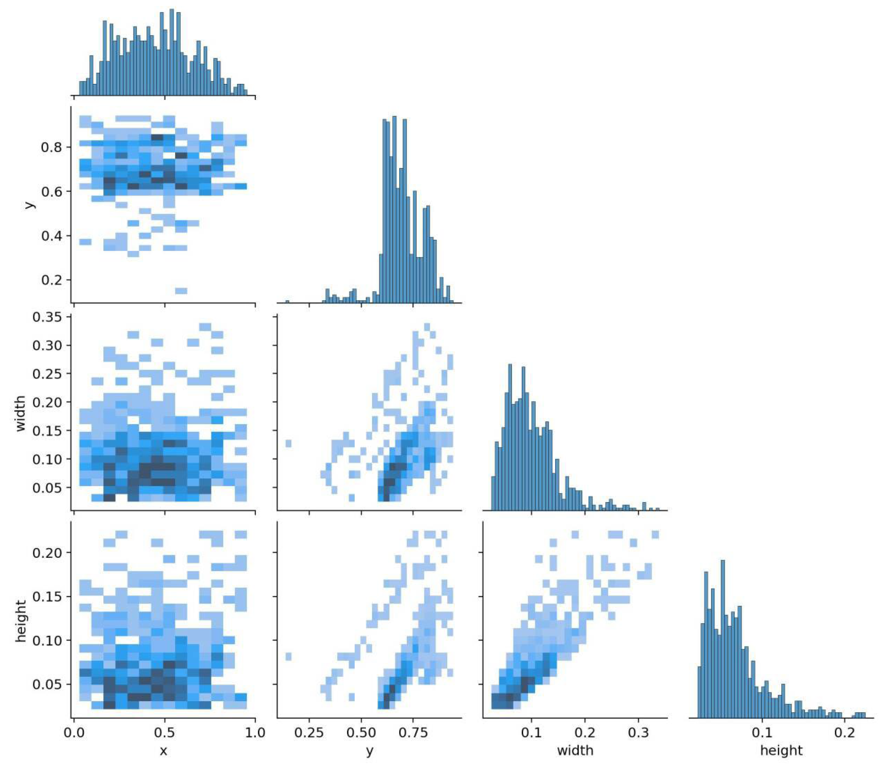
5.1. Introduction to the Dataset
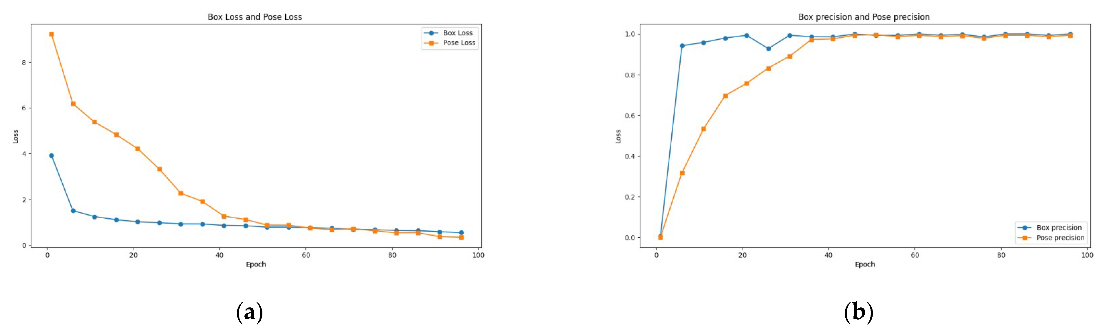
The experiment employs real navigation video data of an unmanned boat model on the water surface for the training and validation datasets of the key point detection model. A total of 996 images were extracted from the video as the model dataset, of which, 712 were used as the training dataset and 284 as the validation dataset.
The experimental simulation of the unmanned boat navigation includes multiple scenarios. The navigation scenario with strong light near the unmanned boat is defined as Scene I. The navigation environment in this scenario is often accompanied by strong light on the water surface, with a mirror effect producing a reflection of the unmanned boat, which affects the accuracy of the unmanned boat’s key point positioning and increases the distance mapping error. The unmanned boat navigation scenario with strong light far away is defined as Scene II. In this scenario, not only does the water surface reflection interfere with the unmanned boat ranging factors, it also has the following characteristics. With the small size of the drone boat imaging, locating the key point is difficult, so the drone boat key point detection model requires better feature extraction ability. Dark light near the drone boat is defined as Scene III. This scene tends to have a dim environment, and the drone boat is not easy to detect, but compared to the other three scenes, it has large-sized imaging of the drone boat and the surface of the water produces less interference. This scene has a small degree of difficulty, with dark light in the distance. In the sailing scene defined as Scene IV, the USV imaging size is small and requires the model to fully learn the USV features. Meanwhile, in order to test the low visibility problem caused by sea fog in a sea surface navigation environment, the experiment defines the scenario with an unmanned boat sailing nearby under foggy conditions with poor visibility as Scene V. Sailing far away under foggy conditions is defined as Scene VI. In the foggy day sailing scenario, the unmanned boat imaging has problems with fuzzy shape and edge features, and the key points are difficult to detect, which greatly tests the robustness of the network. A sample training dataset is shown in Figure 5.
The real distance dataset of the unmanned boat model is collected from a fixed camera position. Ensuring that the optical center of the camera is placed horizontally, the real distance from the camera to the unmanned boat model is measured by a laser rangefinder. A total of 76 typical representative real unmanned boat ranging samples are measured in the four scenarios.

5.2. Model Training

The Yolov11m-pose model architecture is implemented based on pytorch and trained by RTXA5000 GPU with 16 GB of GPU graphics memory for 100 cycles, with eight samples in each training batch. The model uniformly compresses the input image data to a 640 × 640 resolution size. An automatic optimizer selection strategy was used for training and a warm-up strategy was introduced. Also, the dynamic covariate momentum was set to 0.937. The specific training parameters are shown in the Table 1 below.
In addition, to evaluate the performance of the model in the ship attitude recognition task, the experiments were statistically analyzed on the self-constructed dataset. The distribution of the specific dataset is shown in Figure 6. The results show that the distributions of width and height are obviously small, and the height is concentrated in a small range, reflecting that the unmanned ship target is relatively small and difficult to detect. An automatic optimizer selection strategy was used for training, and a warm-up strategy was introduced.
When the training is complete, all the loss functions converge to a stable value and the prediction accuracy stabilizes at a high value, proving the effectiveness of this dataset in the network The results of the training are shown in Figure 7.

5.3. Comparative Testing of Key Point Detection

For the evaluation of the unmanned boat detection model, the four key evaluation indexes used in image recognition were Precision, Recall, mAP50 and mAP50-95.
Among them, Precision indicates the proportion of total samples that are positively predicted by the model. A higher Precision value indicates that more samples are correctly predicted by the model. Precision is mainly used for evaluating the accuracy of the model and preventing the model from making inaccurate detections. The formula is as follows:
P r e c i s i o n = T P T P + F P
where TP is the number of correctly detected targets and FP is the number of samples that were incorrectly detected as a target.
Recall focuses more on those samples whose target areas are missed, and a higher recall value indicates a better model robustness. Recall is used to evaluate the model’s coverage of positive samples, and its formula is expressed as follows:
R e c a l l = T P T P + F N
where FN is the number of targets missed by the model.
The mAP50 index refers to the accuracy of the model when the model intersection and integration ratio (IOU) is greater than 0.5. This ratio mainly reflects the distance between the predicted key points of the unmanned aerial vehicle prediction and its real key points. The closer the predicted key points are to the real key points, the higher the value of mAP50 and the better the robustness of the model. The index is expressed by the following formula.
I o U = A r e a   o f   I n t e r s e c t i o n A r e a   o f   U n i o n
Experiments were performed using the unmanned boat dataset to compare the indicators of different models of YOLO-pose, and YOLOv11m-pose was selected as the detection model in the unmanned boat ranging module. The specific indicators are shown in Table 2.
Yolov11m-pose has a moderate number of parameters, which ensures that it can adequately learn the characteristics of the unmanned boat voyage at the same time. This ensures that the network will not be too large due to the parameter overfitting problems. For rest of the networks such as Yolov11n-pose, the small number of parameters leads to insufficient learning, resulting in low accuracy in predicting the key points of USVs, while the networks such as Yolov11x-pose have a large number of parameters, which leads to overfitting. As a result, the accuracy decreases in the sailing scenarios in the validation set that are missing from the training set and the model migrates poorly. The networks with a large number of parameters such as Yolov11m-pose are optimal in all the metrics. These experiments illustrate the robustness of the structure in the unmanned boat critical point detection task.

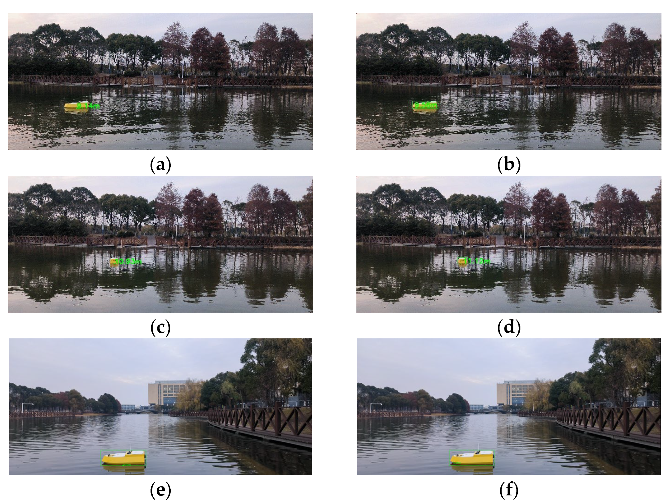
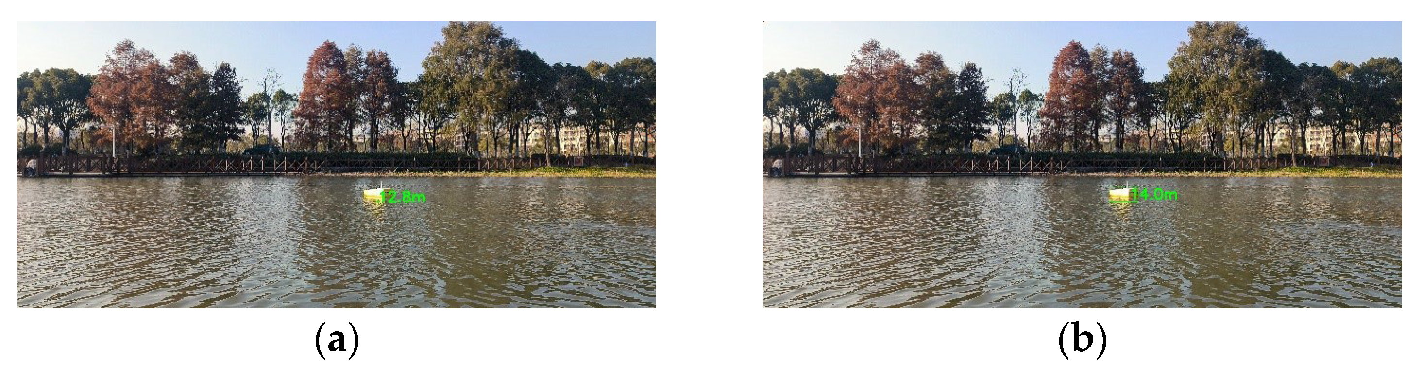
5.4. Distance Mapping Comparison Test

The experiment demonstrates the advantages of the key point-based detection method for ship distance detection by comparing the specific metrics of the original ranging method and the key point-based ranging method. The experiment uses the statistical methods of mean square error (MSE), root mean square error (RMSE), and mean absolute error (MAE) to test the indicators of the two methods.
Among them, the mean square error (MSE) is the average of the squares of the difference between the predicted value and the true value. This index is more sensitive to the large error samples in the experimental data due to the existence of the squares of the difference, and its specific formula is as follows:
M S E = 1 n i = 1 n ( y i y ^ i ) 2
where y i is the true value, y ^ i is the predicted value, and n is the number of samples. A lower value of the mean square error indicates that the predicted value is closer to the true value.
The root mean square error (RMSE) is the square root of the mean square error, which is the unit of the difference with the sample, and can more intuitively respond to the size of the difference between the true value and the predicted value. Its specific formula is as follows:
R M S E = 1 n i = 1 n ( y i y ^ i )
RMSE is also sensitive to outliers with large error values and is the same as the unit of difference, which can reflect the performance of the prediction method more intuitively. The smaller the RMSE is, the more accurate the prediction method is.
The mean absolute error (MAE) is the average of the absolute value of the difference between the predicted value and the true value of all the data samples in the dataset. It is not sensitive to the samples with large errors and can better respond to the effectiveness of the prediction method. Lower values of MAE indicate that the prediction method is more robust. Its calculation method is shown below:
M A E = 1 n i = 1 n | y i y ^ i |
The statistical metrics of the original ranging method and the key point-based ranging show that the key point-based ship distance method basically shows the best performance in each metric for each scenario. The specific metrics are shown in the Table 3 below.

5.5. Sensitivity Analysis

Experiments were conducted to analyze the stability of the hyperparameters on the training results during the training process of the key point detection model. The effects of the number of training rounds and the learning rate on the experimental results are mainly analyzed. The number of training rounds was considered as a way to reduce the size of the test, with ten, fifty rounds and one hundred rounds used as intervals. The experimental results are shown in Table 4.
The experimental results are realistic; as the number of training rounds increases, the accuracy of the given metrics gradually improves. The accuracy of the key point prediction stabilizes near one hundred rounds and meets the requirements of the ranging task.
In addition, an experimentally selected portion of the data samples were analyzed regarding the sensitivity of the physical distance mapping model. The effect of this parameter on the distance mapping system of the unmanned ship was tested by changing the value of the camera focal length measured in the experiment. The specific experimental indexes are shown in Table 5 below.
The experimental results realistically show that changes to the camera focal length parameter introduce some error into the physical distance mapping, and the larger the error in the camera parameter, the larger the error in the distance to the unmanned ship measured by the model.

5.6. Analysis of Results

This paper proposes to sense the distance of an unmanned boat based on key point detection. Compared with the original method, the unmanned boat distance-sensing method based on key point detection can more accurately obtain the key points of distance mapping and improve the accuracy of the distance sensing of the unmanned boat, as shown in Figure 8.
In the dark light environment, due to the irregular attitude of the unmanned boat and the imprecise fitting of the detection frame to the unmanned boat, the unmanned boat distance-sensing method based on the bottom of the detection frame makes the key points of the physical distance mapping inaccurate, resulting in an error in the mapping. In Figure 8a, the actual distance measured by the laser rangefinder is 10.16 m, while the physical distance mapping method based on the bottom of the detection frame measures the distance to be 9.14 m, which is an error of about 10%, making the distance based on the key point detection method more precise. Regarding the error, the unmanned boat ranging method based on key point detection selects a more accurate key point position of the unmanned boat than the physical distance mapping key position of the ship. The measured distance is 9.56, with an error of 5.9%, and the problem of the large detection error is increased due to the inaccuracy of the ship’s attitude and the calibration frame fit. The same physical mapping method based on key points in Figure 8c,d has improved the accuracy of distance measurement. In addition to the different navigation environments, as shown in Figure 8e,f, the data show that the physical distance mapping method based on key points also outperforms the distance mapping method based on detection frames. This illustrates the robustness under different navigation environments of the unmanned boat distance mapping method proposed in this paper.
Under the strong light environment shown in Figure 9, the water surface reflection interferes with the unmanned boat detection. The calibration frame detects the water surface reflection as an unmanned boat, which makes the ranging key point deviate substantially, and the physical distance mapping accuracy decreases. When the water surface unmanned boat reflection is detected as the calibration frame in Figure 9a, the physical distance mapping point is in large error. The measured distance is 12.8 m, which is a 1 m error from the distance measured by the laser rangefinder, 13.8 m, representing an error rate of 7.2%. The method of mapping the actual distance based on the key points of the unmanned boat has a higher accuracy due to the physical distance mapping points being closer to the unmanned boat; thus, the distance of the ship predicted by this method is 14 m, with an error of 0.2 m, and the error rate is 1.4%, which is a greatly reduced error rate. This method better fulfills the task of distance prediction of the unmanned boat under the bright light environment. As shown in Figure 10, the foggy sailing environment resulted in unmanned boat feature extraction difficulties, but the key points of the unmanned boat could still be accurately detected, and the predicted distance of the unmanned boat shows a relatively small error compared with the real value. Meanwhile, regarding the traditional bounding box ranging, due to the interference of the fog and the inaccuracy of the definition of the bounding box, the ranging value has a larger error, which proves that the method based on the detection of the key points still maintains a better robustness in the foggy sea environment.
The statistical indicators of the two methods for unmanned boats in the low-light near-point environment, low-light far-point environment, strong-light near-point environment, and strong-light far-point environment were tested using a real unmanned boat surface navigation dataset. The results show that the physical distance mapping methods based on the unmanned boat’s key points in weak light near point environment, weak light far point environment, and strong light near point environment reach the optimal indicators in MSE, RMSE, and MAE. The MSE and RMSE indicators reached optimal levels in the weak-light far-point environment, and especially in the strong-light environment, while the effect is especially obvious in the strong-light near-point environment. The physical distance mapping method based on the key points of an unmanned boat in the strong-light near-point environment had about 10% greater accuracy than the method based on the bottom of the detection frame, according to the MSE, RMSE, and MAE indicators. Considering the key point mapping method in the strong-light far-point environment, the MSE is improved by 18.9%, while the RMSE and MAE are also improved by about 10%. It is verified that the key point-based physical distance mapping method solves the effects of water reflection and inaccurate calibration frame on the physical distance mapping and improves the robustness of the distance-sensing method in the strong-light environment. In the low-light near-point environment, all the indexes are also improved to a certain extent, which verifies the effectiveness of mapping physical distance based on key points in the low-light environment. At the same time, experiments were conducted in a foggy sailing environment. Due to the ship imaging edge blurring in this scenario, the shape feature extraction is difficult. However, the method proposed in this paper based on YOLO-POSE for key point extraction can efficiently extract the key points of the unmanned boat for physical distance mapping. The experimental results show that under foggy conditions, for the long-distance and near-distance scenarios, the MSE, RMSE, MAE values do not differ greatly from those under clear weather. All the indexes for the method based on key point detection are better than those of the physical distance mapping based on detection frame, which shows that the proposed method can cope with the influence of water vapour, fog and other harsh conditions on the distance mapping of unmanned craft in the marine navigation environment.
The network model for unmanned boat key points detection was also experimentally selected, with yolov11x-pose best predicting the key point locations in the detection task using a real sailing dataset. This model had predicted key points closer to the real key points of the ship. A more accurate prediction of the key point locations of the unmanned boat is crucial for the selection of the real physical distance mapping of key points. By comparing the model’s Precision, Recall, mAP50, and mAP50-95 metrics using the real unmanned boat water surface dataset, we demonstrated the validity of the method for selecting Yolov11x-pose. The results show that Yolov11x-pose optimizes Precision, Recall, and mAP50 metrics based on the real unmanned boat surface navigation dataset, and can more accurately provide a ship’s key points for physical distance mapping.

6. Conclusions

In this paper, we design a distance-sensing framework based on the sailing scene of an unmanned boat. The key point detection model extracts the USV feature detection target to obtain the USV key point, the key point closest to the horizontal plane is used as the distance mapping point combined with the in-camera reference for coordinate transformation to obtain the actual distance from the USV to the camera. The robustness of the selected key point detection model in the task of USV key point acquisition is also illustrated by the Precision, recall, mAP50, and mAP50-95 metrics, and the selected USV key point detection model is able to accurately extract USV key points. Additionally, the metrics such as MSE RMSE MAE illustrate the advantages of the physical distance mapping method based on key points, as well as the previous physical distance mapping method based on detection frames in the common USV navigation environment. The advantages of the physical distance mapping method based on key points and the previous physical distance mapping method based on detection frame are illustrated through the mean square error, root mean square error and average absolute error indexes, while the advantages of the physical distance mapping method based on key points and the previous physical distance mapping method based on detection frame in the common USV navigation environment are explained [34,35,36]. Future research will be directed towards more complex autonomous sensing of unmanned ship navigation [37,38,39,40,41].

Author Contributions

Y.W., conceptualization; Y.S., framework implementation, algorithmic metrics comparison and part of the paper writing; X.C., framework design; Y.Y., dataset collection; H.Z., dataset collection; Z.W., part of the paper writing. O.P. is responsible for the research status survey. All authors have read and agreed to the published version of the manuscript.

Funding

This work was jointly supported by the National Natural Science Foundation of China (52472347, 52331012, 52071200), and the Open Fund of Chongqing Key Laboratory of Green Logistics Intelligent Technology (Chongqing Jiaotong University) (No.KLGLIT2024ZD001).

Data Availability Statement

The data presented in this study are available on request from the corresponding author.

Conflicts of Interest

Author Yuzhen Wu, was employed by the SPG Qingdao Port Group Co., Ltd. Author Zichuang Wang, was employed by the Shanghai Ship and Shipping Research Institute Co., Ltd. The remaining authors declare that the research was conducted in the absence of any commercial or financial relationships that could be construed as a potential conflict of interest.

References

  1. Ismail, A.H.; Song, X.; Ouelhadj, D.; Al-Behadili, M.; Fraess-Ehrfeld, A. Unmanned surface vessel routing and unmanned aerial vehicle swarm scheduling for off-shore wind turbine blade inspection. Expert Syst. Appl. 2025, 284, 127534. [Google Scholar] [CrossRef]
  2. Novák, F.; Báča, T.; Procházka, O.; Saska, M. State estimation of marine vessels affected by waves by unmanned aerial vehicles. Ocean. Eng. 2025, 323, 120606. [Google Scholar] [CrossRef]
  3. Ng, Y.H.; Hou, Y.; Yuan, Y.; Chang, C.W. Underactuated Unmanned Surface Vessel Coverage Path Planning for Marine Pier Inspection. In Proceedings of the OCEANS 2024-Singapore, Singapore, 15–18 April 2024. [Google Scholar]
  4. Nguyen, T.-T.; Hamesse, C.; Dutrannois, T.; Halleux, T.; De Cubber, G.; Haelterman, R.; Janssens, B. Visual-based localization methods for unmanned aerial vehicles in landing operation on maritime vessel. Acta IMEKO 2024, 13, 1–13. [Google Scholar] [CrossRef]
  5. Zhang, H.; Fan, J.; Zhang, X.; Xu, H.; Soares, C.G. Unmanned Surface Vessel–Unmanned Aerial Vehicle Cooperative Path Following Based on a Predictive Line of Sight Guidance Law. J. Mar. Sci. Eng. 2024, 12, 1818. [Google Scholar] [CrossRef]
  6. Li, Y.; Wang, X. Enhancing offshore parcel delivery efficiency through vessel-unmanned aerial vehicle collaborative routing. Int. J. Prod. Res. 2024, 63, 1–27. [Google Scholar] [CrossRef]
  7. Wang, X.; Zhao, J.; Pei, X.; Wang, T.; Hou, T.; Yang, X. Bioinspiration review of aquatic unmanned aerial vehicle (AquaUAV). Biomim. Intell. Robot. 2024, 4, 100154. [Google Scholar] [CrossRef]
  8. Collin, A.; James, D.; Lamontagne, N.; Hardy, R.; Monpert, C.; Feunteun, E. Ultra-high-resolution bathymetry estimation using a visible airborne drone, photogrammetry and neural network. In Proceedings of the XVIIIèmes Journées Nationales Génie Côtier—Génie Civil, Anglet, France, 27 June 2024. [Google Scholar]
  9. Ding, G.; Liu, J.; Li, D.; Fu, X.; Zhou, Y.; Zhang, M.; Li, W.; Wang, Y.; Li, C.; Geng, X. A Cross-Stage Focused Small Object Detection Network for Unmanned Aerial Vehicle Assisted Maritime Applications. J. Mar. Sci. Eng. 2025, 13, 82. [Google Scholar] [CrossRef]
  10. Li, J.; Liu, Q.; Lai, J.; Li, R. A Novel Marine Ranching Cages Positioning System on Unmanned Surface Vehicles Using LiDAR and Monocular Camera Fusion. In Proceedings of the 2024 14th International Conference on Information Science and Technology (ICIST), Chengdu, China, 6–9 December 2024. [Google Scholar]
  11. Vergine, V.; Benvenuto, F.L.; de Giuseppe, S.; Spedicato, M.; Largo, A. An Innovative Monitoring System Based on UAV and Auto-Remote Surface Vessel. In Proceedings of the 2024 9th International Conference on Smart and Sustainable Technologies (SpliTech), Bol and Split, Croatia, 25–28 June 2024. [Google Scholar]
  12. Zhang, G.; Zhang, G.; Yang, H.; Wang, C.; Bao, W.; Chen, W.; Cao, J.; Du, H.; Zhao, Z.; Liu, C. Flexible on-orbit calibration for monocular camera and laser rangefinder integrated pose measurement system. IEEE Trans. Instrum. Meas. 2023, 72, 1–16. [Google Scholar] [CrossRef]
  13. Liu, M.; Feng, G.; Liu, F.; Wei, Z. Accurate 3D Positioning of Aircraft Based on Laser Rangefinder Combining Monocular Vision Measurement. IEEE Trans. Instrum. Meas. 2024, 73, 5036613. [Google Scholar]
  14. Tang, Z.; Xu, C.; Yan, S. A laser-assisted depth detection method for underwater monocular vision. Multimed. Tools Appl. 2024, 83, 64683–64716. [Google Scholar] [CrossRef]
  15. Trinh, H.L.; Kieu, H.T.; Pak, H.Y.; Pang, D.S.C.; Tham, W.W.; Khoo, E.; Law, A.W.-K. A comparative study of multi-rotor unmanned aerial vehicles (UAVs) with spectral sensors for real-time turbidity monitoring in the coastal environment. Drones 2024, 8, 52. [Google Scholar] [CrossRef]
  16. Kieu, H.T.; Yeong, Y.S.; Trinh, H.L.; Law, A.W.-K. Enhancing turbidity predictions in coastal environments by removing obstructions from unmanned aerial vehicle multispectral imagery using inpainting techniques. Drones 2024, 8, 555. [Google Scholar] [CrossRef]
  17. Xie, Z.; Yang, C. Binocular Visual Measurement Method Based on Feature Matching. Sensors 2024, 24, 1807. [Google Scholar] [CrossRef]
  18. Yang, M.; Qiu, Y.; Wang, X.; Gu, J.; Xiao, P. System structural error analysis in binocular vision measurement systems. J. Mar. Sci. Eng. 2024, 12, 1610. [Google Scholar] [CrossRef]
  19. Nguyen, K.; Dang, T.; Huber, M. Real-time 3d semantic scene perception for egocentric robots with binocular vision. arXiv 2024, arXiv:240211872. [Google Scholar]
  20. Wei, B.; Liu, J.; Li, A.; Cao, H.; Wang, C.; Shen, C.; Tang, J. Remote distance binocular vision ranging method based on improved YOLOv5. IEEE Sens. J. 2024, 24, 11328–11341. [Google Scholar] [CrossRef]
  21. Lv, H.; Du, Y.; Ma, Y.; Yuan, Y. Object detection and monocular stable distance estimation for road environments: A fusion architecture using yolo-redeca and abnormal jumping change filter. Electronics 2024, 13, 3058. [Google Scholar] [CrossRef]
  22. Li, J.; Zheng, H.; Cui, Z.; Huang, Z.; Liang, Y.; Li, P.; Liu, P. D-LDRNet: Monocular vision framework merging prior LiDAR knowledge for all-weather safe monitoring of vehicle in transmission lines. IEEE Trans. Intell. Veh. 2024, 1–13. [Google Scholar] [CrossRef]
  23. Liu, J.; Xu, D. A vehicle monocular ranging method based on camera attitude estimation and distance estimation networks. World Electr. Veh. J. 2024, 15, 339. [Google Scholar] [CrossRef]
  24. Li, C.; Yue, C.; Liu, Y.; Bie, M.; Li, G.; Lv, Z.; Li, J. An Improved MonoDepth2 Algorithm for Vehicle Monocular Depth Estimation. Optik 2024, 311, 171936. [Google Scholar] [CrossRef]
  25. Li, H.; Li, L.; Lv, X.; Zhao, R. Intelligent Monocular Visual Dynamic Detection Method for Safe Distance of Hot Work Operation. In Proceedings of the 2025 IEEE 5th International Conference on Power, Electronics and Computer Applications (ICPECA), Shenyang, China, 17–19 January 2025. [Google Scholar]
  26. Wang, J.; Guan, Y.; Kang, Z.; Chen, P. A robust monocular and binocular visual ranging fusion method based on an adaptive UKF. Sensors 2024, 24, 4178. [Google Scholar] [CrossRef] [PubMed]
  27. Jin, Y.; Shi, Z.; Xu, X.; Wu, G.; Li, H.; Wen, S. Target localization and grasping of NAO robot based on YOLOv8 network and monocular ranging. Electronics 2023, 12, 3981. [Google Scholar] [CrossRef]
  28. Qin, Q.; Qiu, C.; Zhang, Z. A Monocular Ranging Method Based on YOLOv8 for UAV Formation. In Proceedings of the 2024 4th International Conference on Computer, Control and Robotics (ICCCR), Shanghai, China, 19–21 April 2024. [Google Scholar]
  29. Parikh, D.; Khowaja, H.; Thakur, R.K.; Majji, M. Proximity operations of CubeSats via sensor fusion of ultra-wideband range measurements with rate gyroscopes, accelerometers and monocular vision. arXiv 2024, arXiv:240909665. [Google Scholar]
  30. Ott, N.; Flegel, T.; Bevly, D. Vehicle to Pedestrian Relative State Estimation via Fusing Ultrawideband Radios and a Monocular Camera; SAE International: Amsterdam, The Netherlands, 2024. [Google Scholar]
  31. Wang, Z.; Li, X.; Chen, P.; Luo, D.; Zheng, G.; Chen, X. A Monocular Ranging Method for Ship Targets Based on Unmanned Surface Vessels in a Shaking Environment. Remote Sens. 2024, 16, 4220. [Google Scholar] [CrossRef]
  32. Wang, G.; Huang, J. Unmanned Ship Ranging and Error Correction Method Based on Monocular Vision. In Proceedings of the 2023 International Conference on Intelligent Perception and Computer Vision (CIPCV), Hangzhou, China, 19–21 May 2023. [Google Scholar]
  33. Zhang, Z. Flexible camera calibration by viewing a plane from unknown orientations. In Proceedings of the Seventh IEEE International Conference on Computer Vision, Corfu, Greece, 20–27 September 1999; Volume 1, pp. 666–673. [Google Scholar]
  34. Zou, Y.; Xiao, G.; Li, Q.; Biancardo, S.A. Intelligent Maritime Shipping: A Bibliometric Analysis of Internet Technologies and Automated Port Infrastructure Applications. J. Mar. Sci. Eng. 2025, 13, 979. [Google Scholar] [CrossRef]
  35. Xiao, G.; Pan, L.; Lai, F. Application, opportunities, and challenges of digital technologies in the decarbonizing shipping industry: A bibliometric analysis. Front. Mar. Sci. 2025, 12, 1523267. [Google Scholar] [CrossRef]
  36. Chen, X.; Wu, S.; Shi, C.; Huang, Y.; Yang, Y.; Ke, R.; Zhao, J. Sensing data supported traffic flow prediction via denoising schemes and ANN: A comparison. IEEE Sens. J. 2020, 20, 14317–14328. [Google Scholar] [CrossRef]
  37. Liu, X.; Qiu, L.; Fang, Y.; Wang, K.; Li, Y.; Rodríguez, J. Event-Driven Based Reinforcement Learning Predictive Controller Design for Three-Phase NPC Converters Using Online Approximators. IEEE Trans. Power Electron. 2024, 40, 4914–4926. [Google Scholar] [CrossRef]
  38. Chen, X.; Hu, R.; Luo, K.; Wu, H.; Biancardo, S.A.; Zheng, Y.; Xian, J. Intelligent ship route planning via an A∗ search model enhanced double-deep Q-network. Ocean. Eng. 2025, 327, 120956. [Google Scholar] [CrossRef]
  39. Sun, Y.; Zhu, H.; Liang, Z.; Liu, A.; Ni, H.; Wang, Y. A phase search-enhanced Bi-RRT path planning algorithm for mobile robots. Intell. Robot. 2025, 5, 404–418. [Google Scholar] [CrossRef]
  40. Zeng, T.; Zhu, D.; Gu, C.; Yang, S.X. An effective fault-tolerant control with slime mold algorithm for unmanned underwater vehicle. Intell. Robot. 2025, 5, 276–291. [Google Scholar] [CrossRef]
  41. Meng, Y.; Liu, C.; Zhao, J.; Huang, J.; Jing, G. Stackelberg game-based anti-disturbance control for unmanned surface vessels via integrative reinforcement learning. Intell. Robot. 2025, 5, 88–104. [Google Scholar] [CrossRef]
Figure 1. Diagram showing overall architecture for distance mapping of unmanned vessels.
Jmse 13 01172 g001
Figure 2. Schematic diagram of C2PSA module structure.
Jmse 13 01172 g002
Figure 3. Schematic structure of key point detection model for unmanned boats.
Jmse 13 01172 g003
Figure 4. The key point views of the front, rear, and side of the USV, where (a) is the front key point view of the USV, (b) is the rear key point view of the USV, and (c) is the side key point view of the USV.
Jmse 13 01172 g004
Figure 5. Sample dataset diagram. (a) sample of Scene I, (b) sample of Scene II, (c) sample of Scene III, (d) sample of Scene IV, (e) sample of Scene V, (f) sample of Scene VI.
Jmse 13 01172 g005
Figure 6. Statistical distribution of datasets.
Jmse 13 01172 g006
Figure 7. (a) The loss function of the detection frame and pose; (b) the change in the prediction accuracy of the detection frame and pose with the number of iterations. In order to facilitate the display of the curve trend, the values for once every five rounds are shown.
Jmse 13 01172 g007
Figure 8. Ranging effect of the unmanned boat, where (a) is based on the actual distance of 10.16 from the bottom of the detection frame, (b) is based on the actual distance of 10.16 from the key point, (c) is based on the actual distance of 12.58 from the bottom of the detection frame, and (d) is based on the actual distance of 12.58 from the key point. (e,f) The value of 5.02 is based on the detection frame method, while the actual distance 5.28, and 5.29 is based on the key point method.
Jmse 13 01172 g008
Figure 9. Ranging effect diagram of the unmanned boat, where (a) is based on the actual distance from the bottom of the detection frame (13.8), and (b) is based on the actual distance from the key point (13.8).
Jmse 13 01172 g009
Figure 10. Ranging samples of unmanned boat sailing scenarios in foggy weather. (a,b) Scenario 5 with an actual distance of 5.284, (a) based on detection frame ranging, (b) based on key point ranging. (c,d) Scenario 6 with an actual distance of 11.56, (c) based on detection frame ranging, (d) based on key point ranging.
Jmse 13 01172 g010
Table 1. Model training parameters.
Parameter TypeParameter Value
Epoch100
Batch size8
Initial learning rate0.01
Weight decay0.0005
Box loss weights7.5
Categorised loss weights0.5
Weights for pose12
IOU0.7
Table 2. Comparison of prediction accuracy metrics for key point detection models.
Precision-PoseRecall-PosemAP50-PosemAP50-95-Pose
Yolov8-pose0.6910.6020.6180.276
Yolov8-pose-P60.8830.7670.7870.518
Yolov11n-pose0.5450.4180.3220.206
Yolov11s-pose0.8170.6970.7140.451
Yolov11l-pose0.9170.7890.8250.567
Yolov11x-pose0.9350.8130.8900.670
Yolov11m-pose0.9400.8450.8980.757
Table 3. Comparison of Accuracy of Physical Distance Mapping Methods.
Based on Detection FrameBased on Key Points
MSERMSEMAEMSERMSEMAE
Scene I0.3950.6280.5080.2840.5330.416
Scene II2.3951.5481.1821.9421.3941.051
Scene III0.9180.9580.7200.9170.9570.716
Scene IV2.8591.6911.2882.8411.6861.466
Scene V1.0961.0470.8690.3430.5860.470
Scene VI3.1731.7821.4992.5701.6031.258
Table 4. Experimental results of training rounds sensitivity analysis.
Precision-PoseRecall-PosemAP50-PosemAP50-95-Pose
50epoch0.9030.7080.7580.524
60epoch0.9120.7490.8120.654
70epoch0.9170.7710.8360.688
80epoch0.9330.8230.8680.719
90epoch0.9360.8270.8720.762
100epoch0.9400.8450.8980.757
Table 5. Sensitivity analysis of physical distance mapping models.
MSERMSEMAE
original + 1501.8171.3481.174
original + 1001.6741.2941.144
original + 501.5521.2461.111
original1.4521.2051.078
Disclaimer/Publisher’s Note: The statements, opinions and data contained in all publications are solely those of the individual author(s) and contributor(s) and not of MDPI and/or the editor(s). MDPI and/or the editor(s) disclaim responsibility for any injury to people or property resulting from any ideas, methods, instructions or products referred to in the content.

