Article

Design and Innovative Application of Ship CCUS Technology Under the Requirements of Green Shipping

1
CAS Key Laboratory of Low-Carbon Conversion Science and Engineering, Shanghai Advanced Research Institute, Chinese Academy of Sciences, Shanghai 201210, China
2
University of Chinese Academy of Sciences, Beijing 100049, China
3
School of Maritime Economics and Management, Dalian Maritime University, Dalian 116026, China
4
CIMC Offshore Co., Ltd., Shenzhen 518000, China
*
Authors to whom correspondence should be addressed.
J. Mar. Sci. Eng. 2025, 13(6), 1157; https://doi.org/10.3390/jmse13061157
Submission received: 7 May 2025 / Revised: 6 June 2025 / Accepted: 8 June 2025 / Published: 11 June 2025
(This article belongs to the Special Issue Sustainable and Efficient Maritime Operations)

Abstract

In the context of green shipping, carbon capture, utilization, and storage (CCUS) technology is widely recognized as an effective approach for maritime emission reduction. However, existing onboard CO2 capture systems (OCCS) face challenges including high retrofit complexity, operational limitations, significant deadweight tonnage loss, and compromising feasibility. This study addresses these issues through modular redesign and standardization of two core components: the capture device and CO2 storage system. We developed clustered storage units to ensure secure CO2 storage while maximizing economic efficiency, with optimal deployment determined through parameter optimization. The work further examines post-capture processing methods and implementation barriers for onboard CCUS, establishing practical pathways to advance decarbonization technologies and mature maritime CCUS industry chains.

1. Introduction

Following the establishment of a global consensus on carbon emission reduction, various industries have implemented mitigation measures [1,2]. However, according to the IEA Global Energy Report 2025 [3,4], global CO2 emissions from energy combustion and industrial processes have continued to rise due to increasing energy demand over the period 1900–2023 [5], reaching 37.6 gigatons (Gt) in 2024 (Figure 1a). In 2018, CO2 emissions from shipping alone amounted to 1.056 billion tons (Figure 1b), representing approximately 3% of global carbon emissions [6], with a more recent update suggesting that this share may be approaching 6% [7]. According to the OECD 2023 report, container ships continue to contribute the highest share of CO2 emissions among all ship types [8] (Figure 1c). Furthermore, the United Nations Conference on Trade and Development (UNCTAD), in its Review of Maritime Transport 2024, emphasizes the urgent need to accelerate decarbonization efforts to achieve the long-term goal of green shipping [9]. This concept focuses on transporting goods through methods that mitigate environmental impact and optimize resource consumption [10,11]. The International Maritime Organization (IMO) projects that, without effective intervention, CO2 emissions from shipping could rise to 1.6 billion tons annually by the mid-21st century (Figure 1d).
In recent years, major international organizations have been actively establishing regulatory frameworks to standardize green shipping practices [9,14,15,16,17,18,19]. The International Maritime Organization (IMO) introduced its Initial Strategy on the Reduction of Greenhouse Gas Emissions from Ships in 2018 [6,20], and subsequently released the 2023 IMO Strategy on Reduction of GHG Emissions from Ships, which included the first revision of the guidelines on the full life-cycle greenhouse gas (GHG) intensity of marine fuels [21]. This revision also updated the global carbon reduction targets for the shipping sector, stating that “carbon intensity should be reduced by at least 40% by 2030 compared to 2008, and total annual GHG emissions from shipping should be reduced by at least 20% by 2030, with a view to achieving a 30% reduction; by at least 70% by 2040, with a view to achieving an 80% reduction; and ultimately to reach net-zero emissions around 2050.” The IMO has also developed comprehensive guidelines for full life-cycle GHG calculations applicable to all types of marine fuels [22]. In addition, the European Union has incorporated the shipping sector into the EU Emissions Trading System (EU ETS) as of 2024 [23].
Under the requirements of green shipping, achieving the aforementioned carbon reduction targets necessitates the adoption of effective emission reduction technologies for ships. Currently, three primary categories of energy-saving and emission-reduction measures are employed in the maritime industry: improvements in energy efficiency, operational management strategies, and the adoption of alternative fuels [24]. Efforts have initially focused on upgrading the primary source of shipboard carbon emissions—the diesel engine—by exploring alternative propulsion technologies such as new energy systems, fuel cells, lithium batteries, and hybrid power systems. However, the relatively low energy density of batteries limits their ability to meet the high-power demands of ocean-going vessels, and their adoption also requires advanced charging infrastructure and substantial port-side support systems. These challenges make large-scale implementation difficult in the near term.
The maritime industry has shifted toward alternative clean fuels to replace fossil fuels and reduce substantial CO2 emissions from combustion. Explored green fuels include liquefied natural gas (LNG), methanol, ammonia, hydrogen, and biofuel [7,17,25,26,27,28,29,30,31,32,33,34,35,36]. Notably, no single alternative energy source can simultaneously achieve high emission reduction rates and low costs. Compared to conventional fossil fuels, the overall emission reduction effect of these alternative fuels ranges from 20% to 95% [37]. For instance, green methanol and ammonia exhibit 60–95% emission reduction efficiencies, highlighting significant decarbonization potential, but their production costs remain high. The liquefied natural gas (LNG) industry is relatively mature, yet its emission reduction efficiency is only about 30%, limiting short-term benefits. As a result, the widespread adoption of alternative fuels is currently constrained. Future research and development may overcome existing production cost barriers.
According to the Intergovernmental Panel on Climate Change (IPCC), carbon capture, utilization, and storage (CCUS) is a foundational technology for achieving significant carbon reductions. This technology aims to capture CO2 generated from energy production and industrial activities, either for direct utilization or long-term storage by injection into suitable geological formations. By doing so, it prevents CO2 from entering the atmosphere and achieves substantial carbon emission reductions [38,39]. As a result, CCUS technology is currently one of the most viable short-term solutions for reducing carbon emissions from ships and meeting international climate targets [40,41,42,43].
The maturity of onshore carbon capture, utilization, and storage (CCUS) technologies positions ship-based CCUS as a promising approach for carbon reduction in the shipping industry. Multiple studies have verified its technical and economic feasibility through full-scale ship trials and simulation analyses [44,45,46,47,48]. Domestic and international researchers have conducted multidimensional studies on shipboard carbon capture technologies, covering applications of carbon solidification methods, optimized system capacity configuration, and energy consumption analysis [45,46,48,49]. These studies confirm that the technology can significantly reduce maritime carbon emissions in the short-term and meet International Maritime Organization (IMO) emission reduction targets [50,51,52]. Some research also indicates that integrating ship-based carbon capture systems with existing infrastructure is feasible, reducing additional investments while supporting zero-carbon emissions goals [53]. The selection of ship-based CCUS technology routes should prioritize efficiency and economy, with capture rate and energy consumption serving as key evaluation metrics. Some studies have optimized energy consumption and costs across system components [41,54,55]. Novel technical solutions—like solid-state carbon storage [56] and membrane capture-liquefaction systems—have been proposed to improve cost-effectiveness. Comparative analyses across vessel types (e.g., LNG carriers, oil tankers) indicate that CCUS technology is most economically viable for ships with high sailing speeds and freight values [57].
Onboard Carbon Capture Systems (OCCS), a key application of CCUS technology in the maritime sector, involve the separation and capture of CO2 from ship exhaust gases, followed by storage and transport for either resource utilization or long-term sequestration underground or at the seabed, thereby achieving permanent CO2 emission reductions [58]. According to an analysis by the China Classification Society (CCS), OCCS technology on ultra-large container ships offers greater economic advantages compared to clean energy alternatives when considering initial capital investment, incremental operating costs, and potential savings on carbon taxes [59]. Researchers have developed predictive models and proposed long-term implementation strategies for this technology [40,43,60,61,62,63].
Recent pilot projects have validated the real-world feasibility of ship-based carbon capture. For example, the ethylene carrier Clipper Eris was retrofitted with a 7 MW amine-based CO2 capture system capable of removing about 70% of CO2 from its main engine exhaust [64]. This project—a collaboration between Solvang, Wärtsilä, and others—includes onboard CO2 liquefaction and storage for later offloading. Similarly, an advanced pilot onboard Crowley’s MV K-Storm container ship [65] will field-test a modular carbon capture unit housed in two 40 ft deck containers (plus a 20 ft CO2 tank), designed to minimize vessel modifications. This system is projected to capture approximately 1 tonne of CO2 daily from the ship’s exhaust. Industry consortia such as Project REMARCCABLE [66] (Stena Bulk, Global Centre for Maritime Decarbonisation, OGCI, etc.) are advancing plans to test CCUS on commercial medium-range tankers within the next few years. These pioneering demonstrations underscore that onboard carbon capture, utilization, and storage (CCUS) has transitioned from conceptual research to deployment on operational vessels. Insights from Clipper Eris, K-Storm, and similar initiatives directly inform the design and innovative application of ship-based CCUS technology under contemporary green shipping imperatives.
However, OCCS systems face a range of specialized requirements, primarily in two areas: capture equipment design, including technological integration, spatial arrangement, and stability under hull motion, and CO2 storage device design [42,67,68]. Hence, how to optimize the CO2 capture and storage system for ships through better design becomes one of the key issues.
The limitations of existing OCCS devices significantly hinder their widespread adoption: firstly, most OCCS systems require customization for specific carbon sources, increasing the complexity of equipment design, production, and operational costs. Conventional ship-based CO2 capture systems typically rely on tall separation towers, resulting in prohibitively bulky installations that challenge spatial constraints aboard vessels. This lack of standardization also hampers system reusability across different scenarios and limits the development of an industrial supply chain. Secondly, current CO2 capture devices fail to adequately address practical challenges such as large variations in flue gas flow, spatial constraints, and integration difficulties with existing ship systems. These systems also lack effective modular design and adaptable pipeline connection solutions, which are critical for practical implementation [41,69].
The limitations of current shipboard CO2 storage systems are also significant, with cost being the primary concern: due to the high material and fabrication costs of high-pressure storage tanks, current CO2 storage systems operate at relatively low pressures (around 1.5 MPa) [70]. Additionally, the tanks are large and bulky, occupying valuable space and reducing cargo capacity, thereby increasing transportation costs [41].
As illustrated in Figure 2, this paper presents a modular OCCS device designed for variable emission sources, achieved through the standardization and modularization of functional units. This design addresses the emission reduction needs and process flexibility requirements of mobile carbon sources such as ships, enhancing the adaptability of the OCCS to varying flue gas flow rates and conditions. It enables timely adjustments in equipment operation based on variations in gas volume and composition, facilitating the installation, maintenance, upgrades, and operation of the OCCS in diverse scenarios. By reducing production costs and technical barriers, this approach ultimately aids in the formation of a standardized equipment industry chain for OCCS, supporting mass production, installation, maintenance, and upgrades across various operational scenarios.
To address the limitations of existing CO2 storage devices, this paper proposes a “small-sized CO2 storage unit group” that can be integrated into a standard container, while simultaneously improving the maximum limit of CO2 storage pressure (exceeding 1.5 MPa) and reducing storage tank costs, overcoming the limitations of low-pressure CO2 storage on ships. Additionally, the most appropriate CO2 storage unit size and layout within the container are determined through economic analysis.
To address the limitations of conventional maritime CO2 capture and storage systems this study proposes the following innovations: Section 2 introduces a modular ship-based CO2 capture system designed for containerized integration, demonstrating adaptable assembly configurations and scalable gas-processing capabilities. Section 3 presents a compact, container-compatible CO2 storage unit. By defining two critical performance metrics (cost per unit capacity and mass per unit capacity), this section derives an optimized design through parametric analysis and validates its economic superiority via case studies. Section 4 critically examines systemic challenges of maritime CCUS adoption, including technical implementation barriers, safety and regulatory protocols, logistical coordination gaps, and economic viability constraints. Section 5 synthesizes the study’s contributions and outlines actionable pathways to advance the commercial maturity of ship-based CCUS technologies.
In summary, the design proposed in this paper demonstrates theoretical innovativeness and provides practical inspiration for advancing green ship carbon-reduction technologies.

2. Design of CO2 Capture System for Marine Vessels

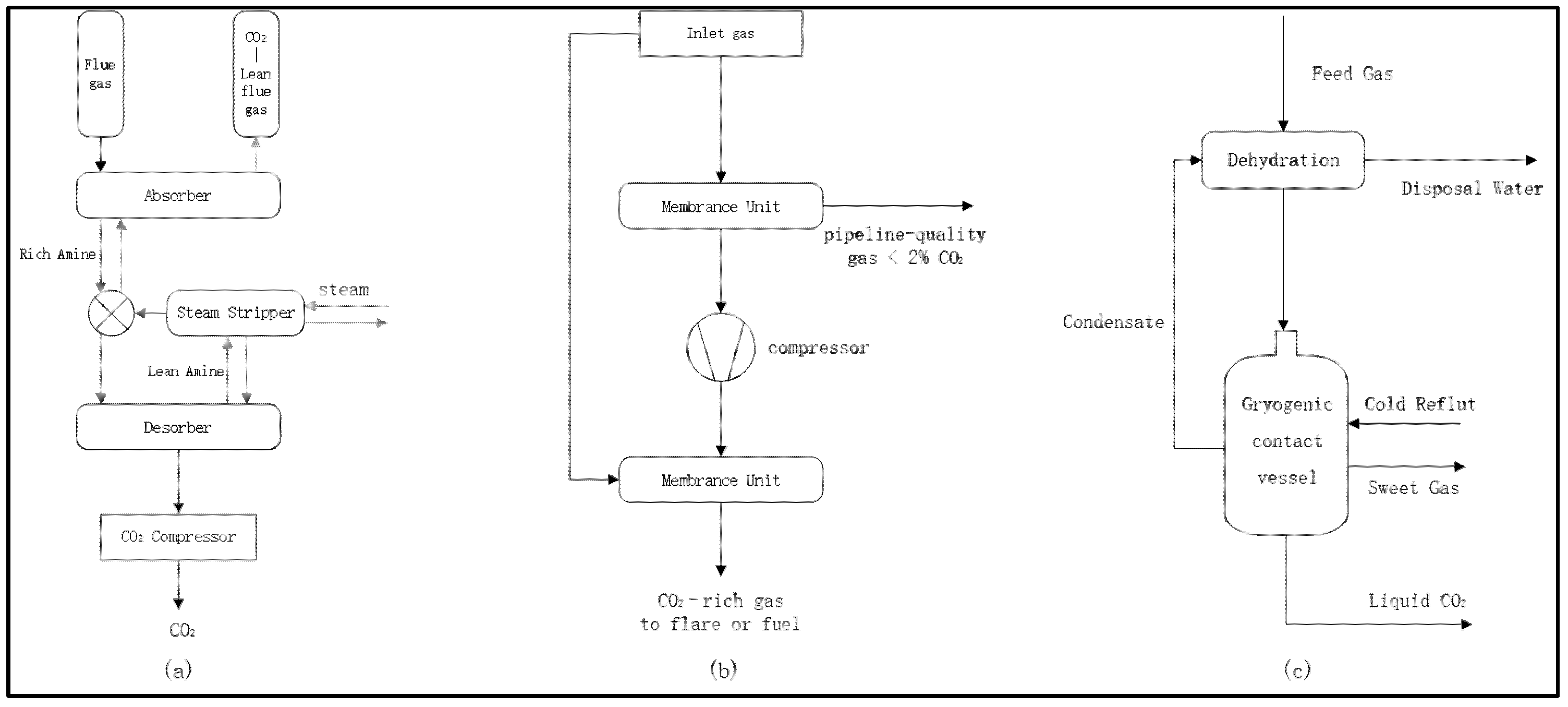
2.1. Analysis of Ship Flue Gas Components and Existing Capture Technology

Exhaust gases emitted from ships are primarily generated by the combustion of engine fuels. The chemical composition of these gases includes gaseous substances such as carbon dioxide (CO2), carbon monoxide (CO), nitrogen oxides (NOx), sulfur dioxide (SO2), and volatile organic compounds (VOCs), along with particulate matter like black carbon (BC) and particulate organic matter (POM) [71]. Among these, CO2 is the primary product of combustion. Several countries and regions have now established clear limits on ship emissions [7].
CO2 emissions are typically calculated based on fuel consumption and serve as a benchmark for estimating other pollutants. Under normal combustion conditions, almost all of the carbon in fuel is converted to CO2, with only a small fraction remaining in the form of CO and hydrocarbons (HC).
The main methods used to estimate emissions from ships are generally categorized into two approaches: the “top-down approach” [72,73] and the “bottom-up method” [74]. Table 1 [75,76,77,78,79,80] presents the annual fuel consumption and various types of emissions from ships.
Under normal operating conditions, the exhaust manifold temperature of ocean-going vessels exceeds 500 °C, while the temperature after the waste heat recovery system remains above 150 °C. The exhaust pressure typically ranges between 0.1 and 0.2 MPa. The total exhaust gas volume is substantial, while the CO2 partial pressure remains low. For most vessel types, CO2 accounts for 3–7% of the exhaust volume, with a theoretical maximum of 15%. The exhaust gas also contains a high concentration of nitrogen (N2 > 70%) and other gases [81].
According to the IPCC Carbon Sequestration Report [82], the four fundamental CO2 capture technologies are pre-combustion capture, oxygen-enriched combustion capture, post-combustion capture, and industrial process capture systems. Common CO2 capture methods for onshore power plants and industrial processes include chemical absorption, physical absorption, physical adsorption, membrane separation, and emerging low-temperature liquefaction and separation techniques. When applied to the limited space available on ships, chemical absorption, membrane separation, and cryogenic separation are considered the most promising options for CO2 reduction [24,83]. Figure 3 below illustrates the general design of these three different CO2 capturing processes. Table 2 compares these capture methods in terms of efficiency, energy demand, space/weight requirements, and operational considerations. Miller et al. [84] provided an economic comparison of various CO2 capture methods, summarized in Table 3.
Chemical absorption suffers from bulky equipment, excessive energy consumption, and corrosion risks. The cryogenic separation method is extremely energy-intensive, carries safety risks of pipeline clogging due to dry ice, and remains insufficiently mature for current research applications.
In comparison, despite the challenges of separation efficiencies of membrane separation methods, membrane systems are compact and chemical-free, which is a great advantage for confined spaces like ships. Therefore, the membrane separation method remains the primary candidates for ship CCUS in the near term.
Polyimide-based membranes [91,92] represent a high-performance material for CO2 capture due to their exceptional CO2 selectivity, permeability, thermal stability, and chemical-mechanical durability [93]. For marine applications, these membranes offer distinct advantages: outstanding resistance to salt spray corrosion, moisture-heat aging, and contamination; low water absorption; long-term reliability; and modular design feasibility. Compared to zeolite molecular sieves [94], polyimide membranes require less extensive flue gas pretreatment. Relative to metal-organic framework (MOF) membranes [95], they demonstrate superior thermal stability and enhanced tolerance to humidity, elevated temperatures, and harsh marine operating conditions. Thus, in the Section 2.2.1, polyimide membranes are selected as the exemplary material for system design.

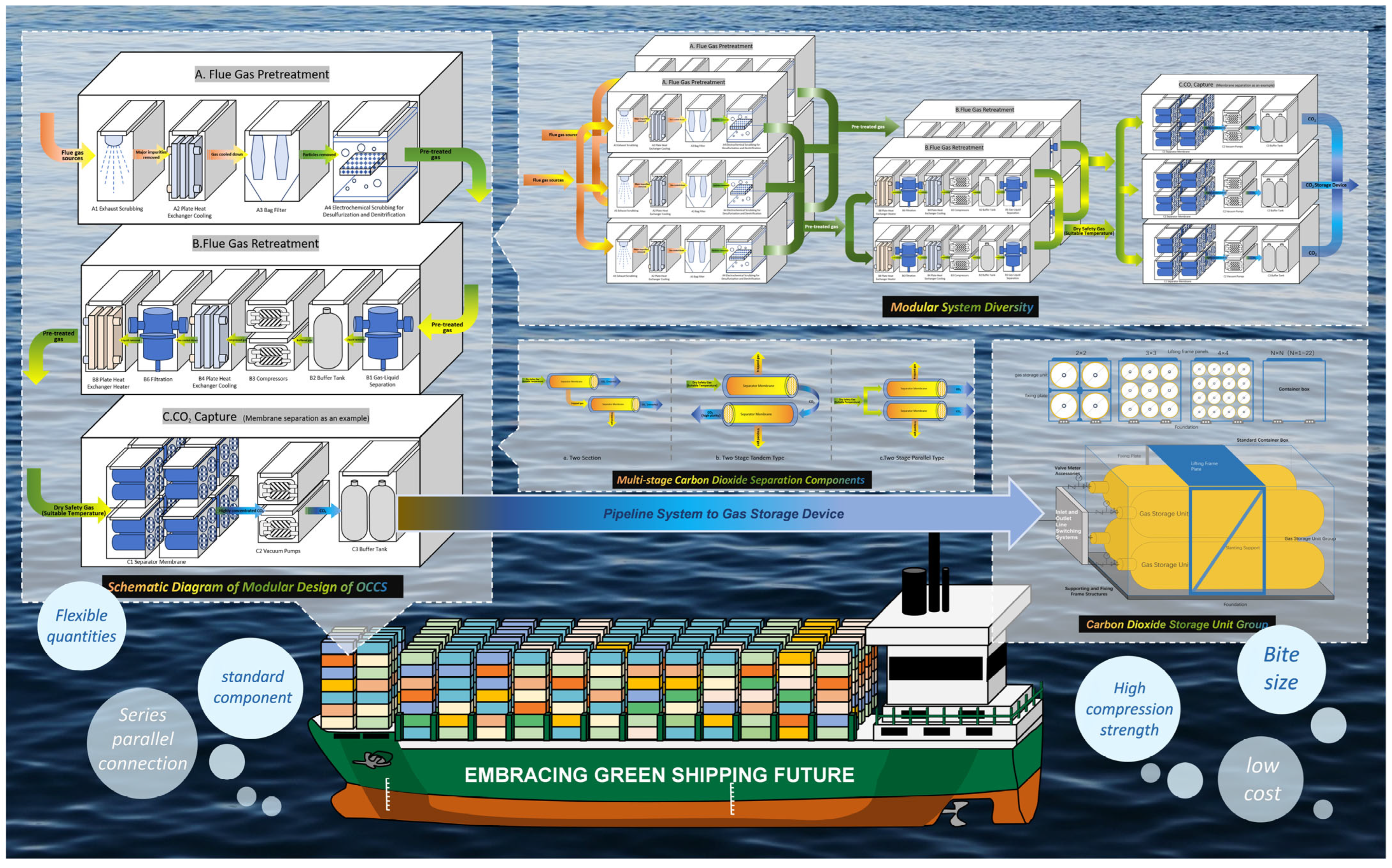
2.2. Modularized Ship CO2 Capture System Design

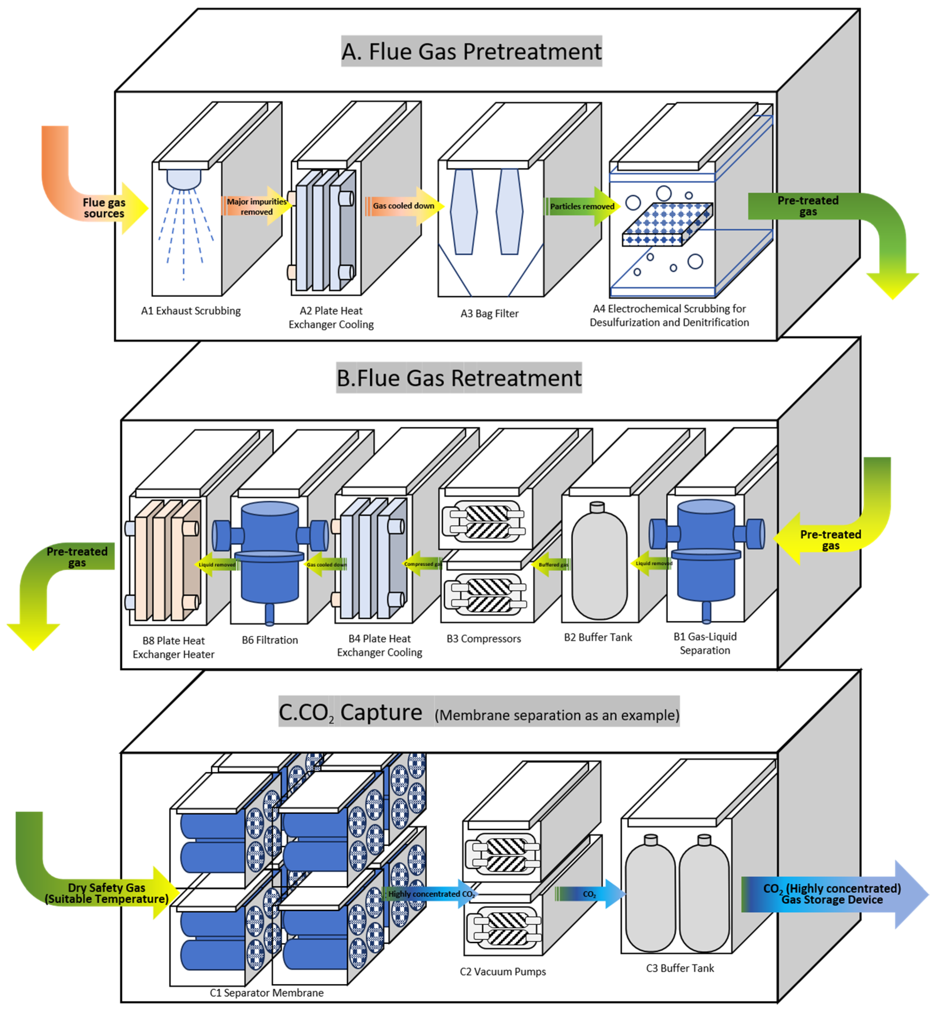
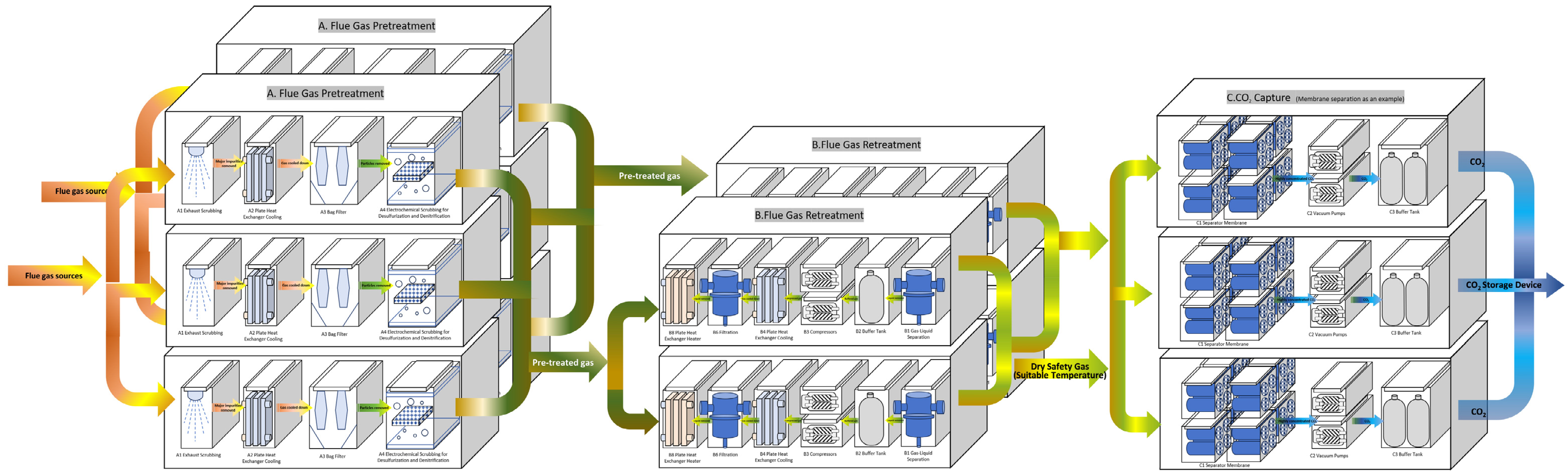
2.2.1. Functional Unit Standard Parts Design

Table 4 outlines the three primary modules of the carbon capture process proposed in this study, along with their respective internal functional units.
All functional units mentioned above are standardized in design, featuring uniform base dimensions, frame structures, and other components, enabling auxiliary units to be easily integrated into standard containers. The sequence and number of these functional units are not rigidly fixed; they can be flexibly adjusted based on the characteristics of the incoming gas. Units can be added, removed, or rearranged in series or parallel configurations, as the modular container system is pre-designed with reserved space for various processing components, allowing for adaptable reconfiguration. The foundational schematic of the overall design is illustrated in Figure 4.
The flue gas, transported via pipeline at a very high temperature (typically 300 °C or higher), enters Module A for pretreatment. The process involves sprinkler scrubbing and coil cooling to achieve preliminary temperature reduction and overall heat energy decrease. The flue gas then passes through a dedusting unit and a desulphurization-denitrification unit to remove impurities before entering Module B. In Module B, a gas-liquid separator removes most water from the gas, a compressor increases gas pressure, and a coil cooler cools the gas to prevent overheating. A reserved coil heater can be activated if the gas temperature is too low, ensuring suitable temperature and pressure conditions before the gas enters the CO2 separation unit.
  • Module A. Flue gas pretreatment (Figure 5)
A1. Tail Gas Washing Unit: This unit removes major impurities from the incoming flue gas, adjusts its composition, and prevents particulate matter from clogging pipelines and downstream components. For instance, when the flue gas contains high concentrations of acidic gases, a tailored scrubbing solution can be applied in the washing section to remove acidic and soluble impurities via spray treatment. Combined with a graded filtration system (coarse, medium, and fine), the unit effectively eliminates large dust particles, fine particulates, and micro-impurities, thereby protecting the integrity of the subsequent membrane module.
A2. Cooling Unit: This unit lowers the temperature of the incoming flue gas to minimize water vaporization and prevent high temperatures from compromising equipment, piping, and valve integrity. For example, a high-efficiency air-cooled or water-cooled heat exchanger can be employed to bring the gas to an optimal temperature for subsequent filtration and treatment.
A3. Dedusting Unit: This unit ensures the effective removal of fine particulate matter from the flue gas. A multi-stage electrostatic precipitator combined with bag-type dust collectors may be used to achieve high-efficiency particulate capture.
A4. Desulfurization and Denitrification Units: These units target the removal of acidic gases and nitrogen oxides from the flue gas to prevent rapid corrosion of downstream systems. In scenarios where sulfur and nitrogen content is elevated, advanced treatment technologies such as membrane absorption coupling and electrochemical scrubbing can be employed. These methods utilize membrane separation and electrochemical oxidation-reduction reactions to reduce sulfur and nitrogen levels, followed by micro-channel selective catalytic reduction (SCR) to convert residual compounds into harmless nitrogen and water.
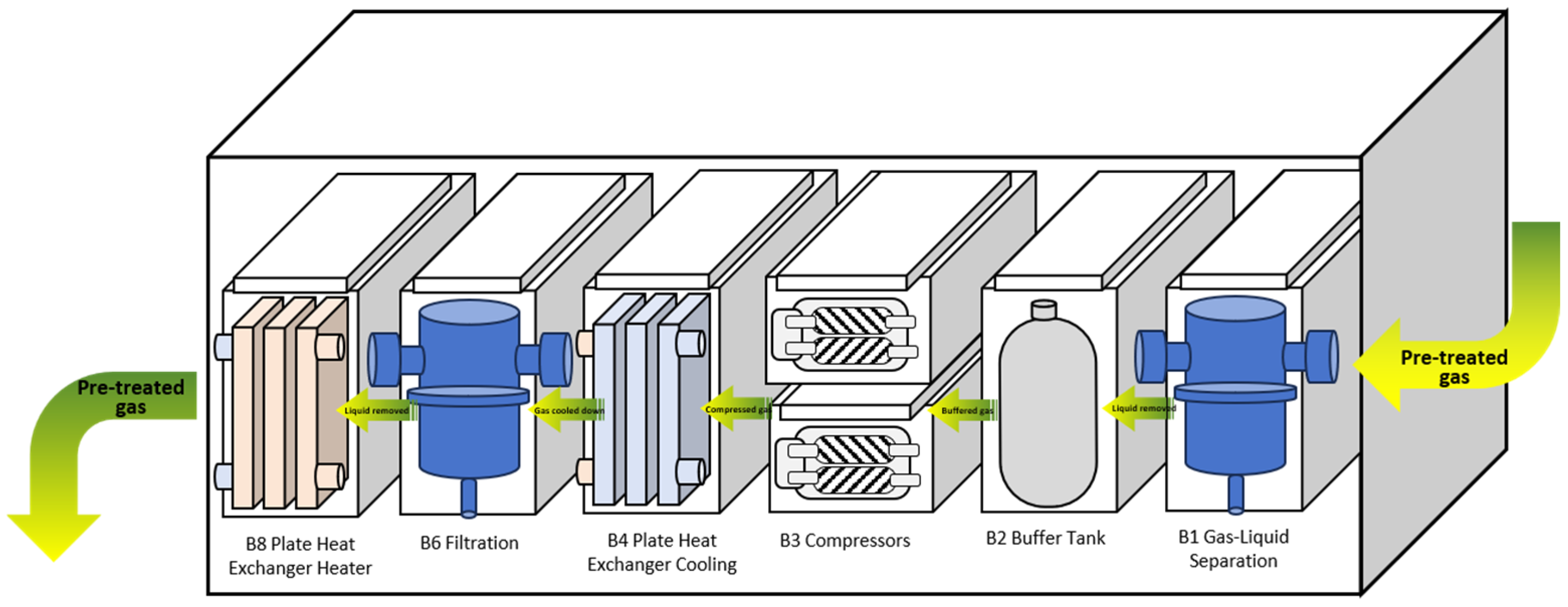
  • Module B. Flue gas reprocessing (Figure 6)
B1. Gas-Liquid Separation Unit: Used to initially separate gas and entrained liquid impurities. The purified gas continues to downstream processing, while the separated liquid is periodically discharged into a designated recovery tank via external piping.
B2. Buffer Tank Unit: This unit stabilizes the pressure and flow rate of the gas stream to ensure smooth operation of subsequent components.
B3. Compression Unit: Used to increase the gas pressure to meet CO2 separation requirements. Typically, an integrated scroll or screw compressor is utilized; under specific conditions, a multi-stage compressor may also be considered.
B4. Cooling Unit: A heat exchanger is employed to further reduce the gas temperature, thereby enhancing the efficiency of subsequent CO2 separation processes.
B5. Secondary Gas-Liquid Separation Unit: This stage removes residual water droplets from the gas stream, ensuring minimal moisture content.
B6. Filtration Unit: High-precision filters are used to eliminate residual fine particulate matter and ensure the cleanliness of the gas.
B7. Buffer Tank Unit: Provides additional pressure stabilization to maintain operational consistency before CO2 separation.
B8. Heating Unit: The gas may be appropriately heated based on process requirements to meet the temperature requirements for the next step of membrane separation.
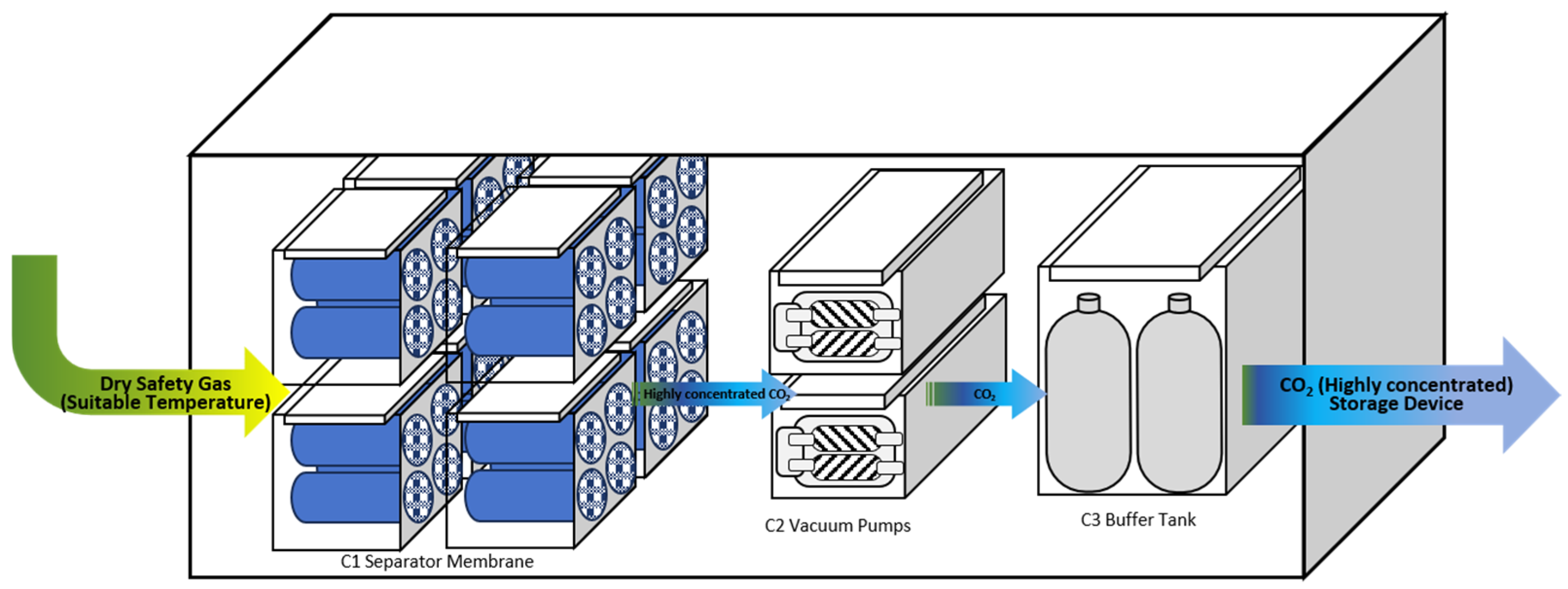
  • Module C. CO2 Membrane Separation (Figure 7)
This stage applies to various CO2 separation technologies, including chemical adsorption, physical adsorption, membrane separation, and low-temperature distillation. Considering the spatial and operational constraints of shipboard environments, this section adopts the membrane separation method for the demonstration of the modular standard parts process design.
C1. Membrane Module: This unit employs composite membrane materials with high CO2 selectivity and permeability. A common choice is a polyimide-based membrane doped with specific metal ions or nanoparticles to enhance separation performance.
The membrane module design is flexibly configurable based on the required CO2 capture purity, flue gas composition, and flow rate. Key design features such as internal gas distributors and deflectors ensure uniform gas distribution across the membrane surface, mitigate concentration polarization, and enhance CO2 separation efficiency and membrane stability.
C2. Vacuum Pump: Activated under conditions of low inlet pressure, volume, or CO2 concentration. It assists in drawing the gas stream through the membrane, improving separation performance under suboptimal conditions.
C3. Buffer Tank Unit: Temporarily stores the captured CO2 and serves as a pressure buffer to stabilize flow before compression or storage stages.
To improve overall energy efficiency and reduce operating costs, waste heat recovery or other integrated heat exchange systems [96] may be incorporated into the design where feasible.
After the CO2 capture system, the CO2 in the buffer tank C3 has reached the purity required for capture, and it can be connected to the transport pipework onboard the ship via a double-valve connector after being compressed into a stable liquid phase and then transported to the CO2 storage unit.
To support the proposed modular OCCS design, physical fabrication of the system’s key components has been carried out in collaboration with China International Marine Containers (Group) Co., Ltd. (Shenzhen, China) As of the time of writing, major units—including the membrane separation housings, absorption modules, CO2 liquefaction chambers, and pressure vessels—have been individually manufactured and dry-tested. Also, module-to-module mechanical integration has been iteratively tested to evaluate physical interface compatibility, structural tolerances, and operational layout. Membrane selection is a key part in this system, tested membranes are purchased from different suppliers. See Figure 8 below for the schematic design of this system.
The system employs a two-stage membrane separation configuration to progressively concentrate CO2 from an initial ~7% concentration in the exhaust gas. Stage 1 involves compression, heat exchange, and a primary membrane unit, achieving ~20–30% CO2 capture. The permeate stream from this stage (containing ~30–40% CO2) undergoes further compression before entering Stage 2 for secondary separation, yielding product gas with over 50% CO2 concentration. Vacuum pumps are integrated to enhance the membrane driving force, while partial gas recycling improves overall efficiency. Buffer tanks stabilize system pressure and facilitate modular integration.
In parallel, ongoing research focuses on membrane performance screening and long-term operational validation under a separate track. Upon completion, these findings will be reported in a dedicated publication addressing system efficiency, material selection, and performance stability, with explicit reference to the design framework outlined herein.

2.2.2. Diversity in System Construction

  • Module C. Lap Diversity for CO2 Separation (Membrane Separation as an Example)
Depending on the specific application scenario, this module can be used with multi-stage, multi-stage parallel or series-connected membrane module units. As an example, the concept of “multi-stage CO2 separation modules” is introduced with two-stage, two-stage series and two-stage parallel CO2 separation modules:
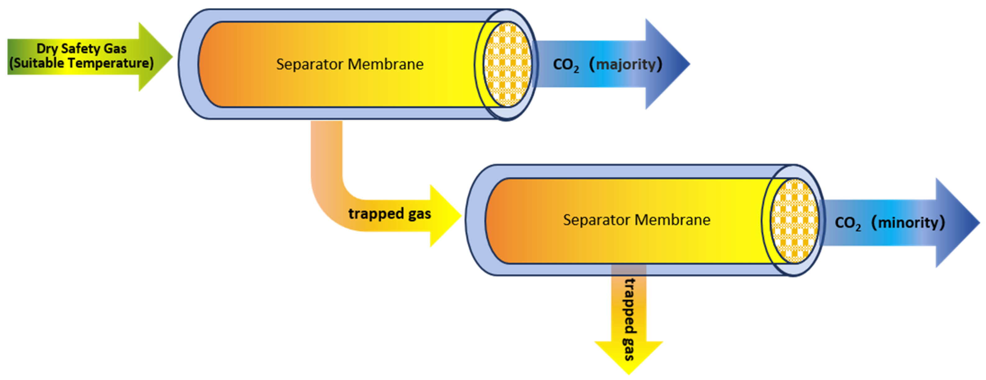
  • Two-stage: As illustrated in Figure 9, the two-stage structure is typically used to increase the total amount of carbon dioxide separated and the proportion of carbon dioxide separated from the mixture. First, after a series of treatments, the gas enters the first-stage CO2 separation unit. Driven by a certain pressure or concentration difference, CO2 begins to permeate through the first-stage membrane module unit to the opposite side of the membrane, while the remaining gas is retained on the feed side. The separated CO2 gas is drawn by a vacuum pump into the buffer tank unit and then injected directly into the storage module. The retained gas from the first stage is directed via pipeline to the second-stage CO2 separation unit for secondary separation of any remaining CO2.
  • Two-stage tandem connection: As illustrated in Figure 10, the tandem structure is primarily used to improve the purity of separated CO2. After the gas undergoes a series of treatments, it enters the first stage of the CO2 separation unit. Driven by a pressure or concentration difference, the CO2 begins to permeate through the first stage membrane module, while the remaining gas is left outside the membrane. Since this retained gas is already clean, it can be uniformly discharged through the external exhaust pipeline. Depending on the pressure on both sides of the membrane, the vacuum pump unit may be activated to accelerate CO2 filtration. The gas is then buffered in the tank and sent to the second stage of the CO2 separation unit. The second stage operates similarly to the first stage, further filtering and purifying the CO2. It is important to note that the materials used for each stage of the CO2 separation process can vary and be customized based on the components and filtration sequence.
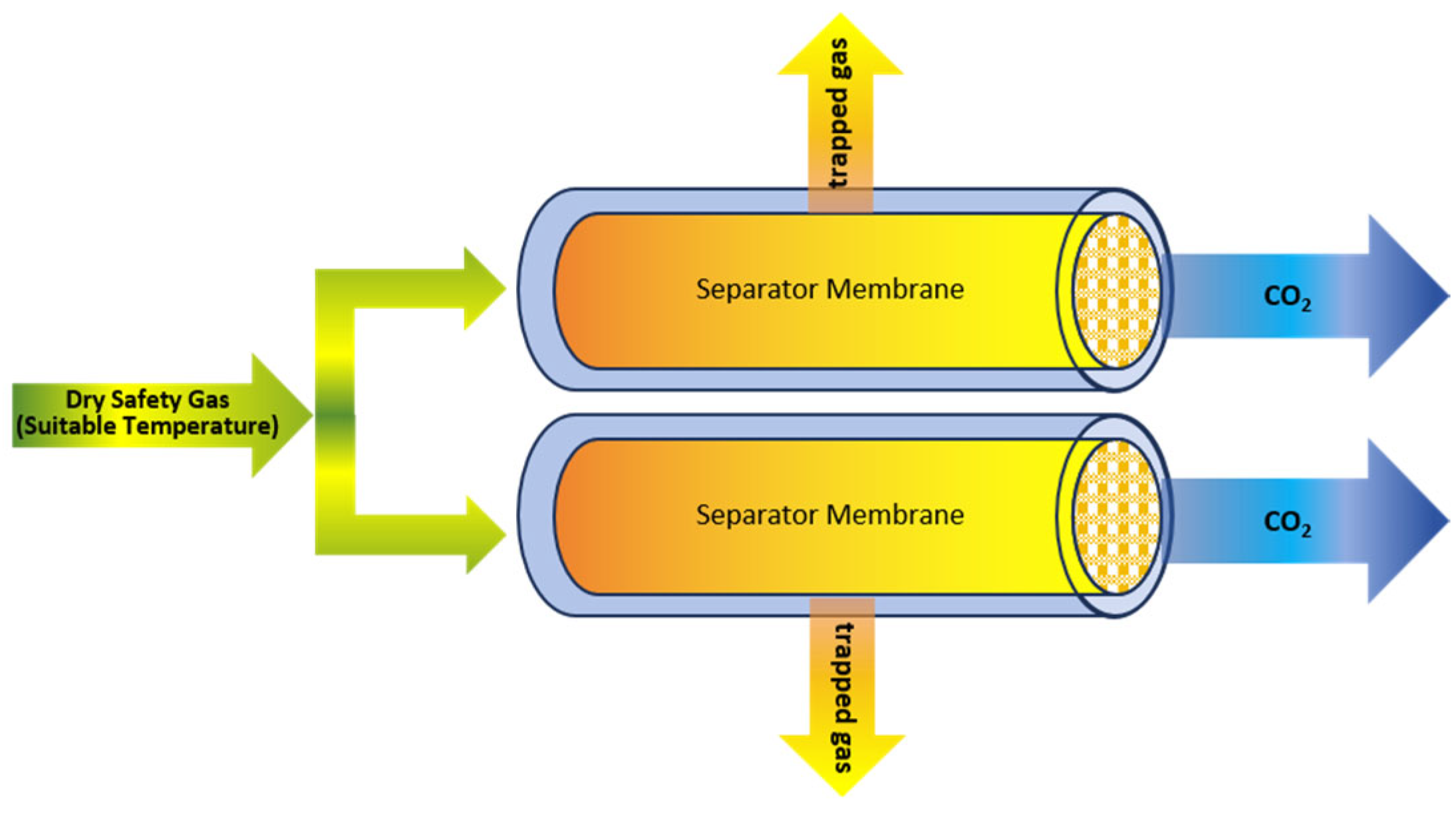
  • Two-stage parallel connection: As illustrated in Figure 11, the parallel connection structure is primarily used to reduce CO2 separation processing time and increase the amount of CO2 captured simultaneously. When the incoming gas flow rate increases significantly, this method allows for an increased total gas handling capacity of the system. It can be understood as a direct parallel connection of two primary membrane separation units.
In special application scenarios, a combination of multi-stage and series-parallel configurations can be used to further enhance both the purity and capture rate of CO2. Each stage of the membrane material can be selected individually based on the actual gas composition, flow rate, and target capture purity. Additionally, the inclusion of three-way valves and piping between membrane modules allows for flexible strategy adjustments and synergistic operation.
  • Diversity of the CO2 capture system
As illustrated in Figure 12, due to variations in application scenarios, gas composition, and flow rate, the standard modules designed in this paper allow for flexible series and parallel configurations of different modules in the CO2 capture system. This enables adjustment of the output of individual functional units, reordering of unit sequences, and modification of connection methods and numbers across modules. As a result, the system achieves both large-scale flue gas processing and high-precision CO2 capture without being constrained by fixed processing capacities, and without the need to compromise between throughput and accuracy under special conditions.

2.2.3. Advantage: Modular Design and Standardized Components

  • Standardization advantages: Standardized dimensions can facilitate serial and parallel integration, easy installation on fixed-size base supports, and the formation of a “containerized” complete process system. This allows for flexible disassembly, assembly, maintenance, and adjustment across different ship scenarios, ultimately reducing industrial production costs and promoting the development of a dedicated equipment processing industry chain.
  • Economic and efficient: The modular design significantly reduces equipment manufacturing, installation, and maintenance costs, improving long-term operational economy.
  • High flexibility, small volume, and compactness: Modular design enables each unit to be flexibly assembled or disassembled based on actual flue gas emissions, space layout, and operational needs in different applications.
  • High-quantity, high purity, high-speed: Through optimized flue gas pretreatment and multi-stage membrane module separation, the system can efficiently capture CO2 from the incoming flue gas, enhance both the capture rate and purity.

3. Design of CO2 Storage and Transportation System for Marine Vessels

A study [70] indicates that as liquefaction pressure increases, the cost of liquefaction and pumping systems decreases, but the cost of storage tanks and CO2 carriers rises. Therefore, high-pressure storage tank costs directly affect marine CO2 storage.
Current Pilot OCCS systems often use a single-tank storage. Although a single tank may seem more material-efficient in terms of wall-to-volume ratio, it presents significant limitations in terms of handling, maintenance, and safety.
Therefore, to resolve these challenges, this study proposes a modular CO2 storage unit compatible with standardized containers, which can ensure secure storage while maximizing economic efficiency. Modular vessels can be manufactured using seamless steel pipes, improving safety and reducing production complexity and cost. The smaller-unit design also improves operational flexibility and fault isolation, since a failure in one vessel does not compromise the entire system. By replacing conventional large-scale storage tanks with a standardized container framework, this design enables scalable deployment, rapid installation, and adaptability to diverse storage volumes and pressure-phase conditions.
This study rigorously analyzes material costs, pressure resistance, weight, and structural integrity of the CO2 storage unit, introducing two critical performance metrics—‘cost per unit capacity’ and ‘weight per unit capacity’—to compare designs across material choices and dimensional configurations, ultimately identifying the optimal unit dimensions that balance safety and cost-effectiveness. Furthermore, the system integrates structural reinforcements, valve-meter assemblies, and auxiliary components to ensure operational stability, thereby improving the efficiency and adaptability of maritime CO2 storage systems while complying with high-pressure safety standards and minimizing costs.

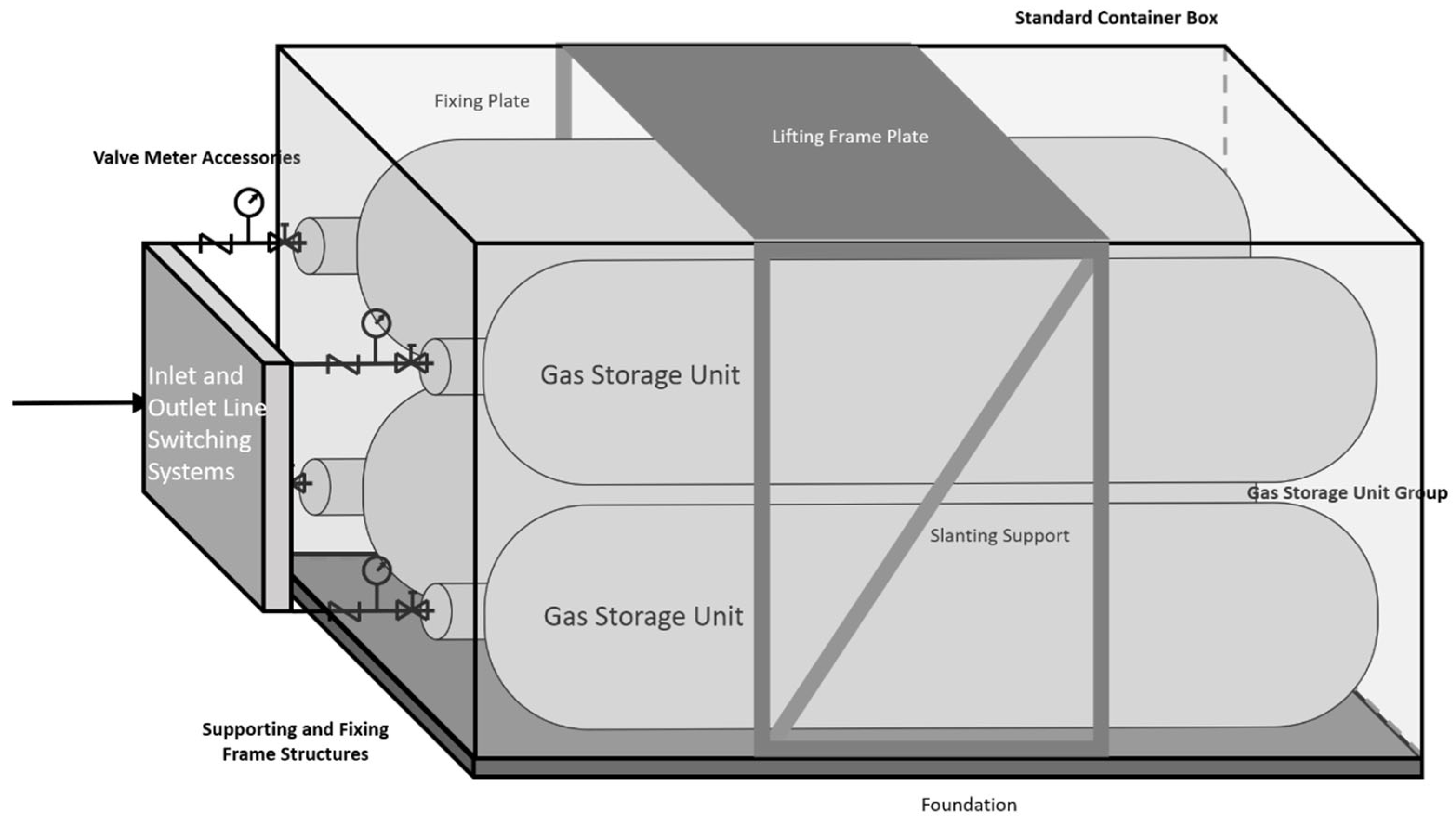
3.1. Design of Small-Sized CO2 Storage Units and Their Fittings

The CO2 storage units are interconnected via a modular high-strength framework fabricated from lightweight, corrosion-resistant, and pressure-tolerant advanced materials, such as aluminum alloys or high-strength steel alloys. Additionally, the incorporation of composite materials—such as carbon fiber-reinforced polymer matrix composites—leverages their high strength-to-weight ratio to minimize unit weight and structural load while maintaining pressure integrity. Each unit is securely anchored within a standardized container, forming an integrated assembly that ensures structural stability during transit. This configuration prevents displacement, collisions, or hazardous scenarios, even under mechanical stresses such as vibrations or impacts.

3.1.1. CO2 Storage Unit Group Tank Structure

The CO2 storage unit design must accommodate CO2 phase behavior. As CO2 is typically liquefied for large-scale transport, storage temperature and pressure must be maintained between the triple point (−56.6 °C, 0.518 MPa) and critical point (30.98 °C, 7.377 MPa) to prevent phase transitions [70,97,98]. Ambient temperature fluctuations induce internal pressure variations, necessitating precise control systems. To ensure secure storage while maximizing economic efficiency, this study proposes a high-pressure CO2 storage device compatible with standardized containers (Figure 13). The vessel features a maximum pressure tolerance of 7.35 MPa (operational pressure < 7 MPa), achieved through reduced tank diameter. This design simultaneously enhances structural integrity, lowers fabrication costs, and enables flexible spatial configuration through modular assembly within the containerized framework.
The CO2 storage units are configured in two primary orientations: horizontal grid-based arrays and vertical stacks. Deployment quantities are adaptable based on the stored gas’s target pressure and phase conditions. For horizontal configurations, modular scaling permits array dimensions ranging from 1 × 1 to 20 × 20 units. Vertical single-layer arrangements accommodate 2–120 units, with capacity determined by the storage unit diameter to maintain structural integrity.
The quantity of CO2 storage units within a modular group can be dynamically optimized based on the stored gas’s pressure, phase state, and operational requirements. For instance, systems storing high-pressure liquefied gases may scale unit quantities proportionally to accommodate large-capacity storage demands, whereas configurations handling gases with significant pressure fluctuations often minimize unit counts to amplify the pressure-carrying capacity of individual units.

3.1.2. Auxiliary Safety Devices

Safety is paramount in high-pressure vessel design. As illustrated in Figure 14, this system incorporates auxiliary safety mechanisms—including valve-gauge assemblies and structural reinforcements—to mitigate risks for modular storage units during dynamic maritime operations.
The modular gas storage unit, designed as a cylindrical pressure vessel, integrates pressure sensors, flow sensors, liquid-level detectors, safety-relief valves, and an emergency venting system. These components transmit real-time telemetry (temperature, pressure, liquid level) to centralized monitoring systems while autonomously initiating emergency protocols (e.g., pressure relief, alarms) during abrupt fluctuations.
The compact gas storage unit is secured within the container via a reinforced framework (supports, bases, fixed plates, inclined braces, and lifting plates) to ensure structural stability. Vibration-damping interfaces (e.g., rubber gaskets) at support-unit contact surfaces mitigate mechanical stresses induced by maritime turbulence. Additionally, continuous sensor-based monitoring ensures real-time detection of operational anomalies, enabling prompt safety interventions.

3.2. Comparison of Economic Safety of CO2 Storage Unit Size

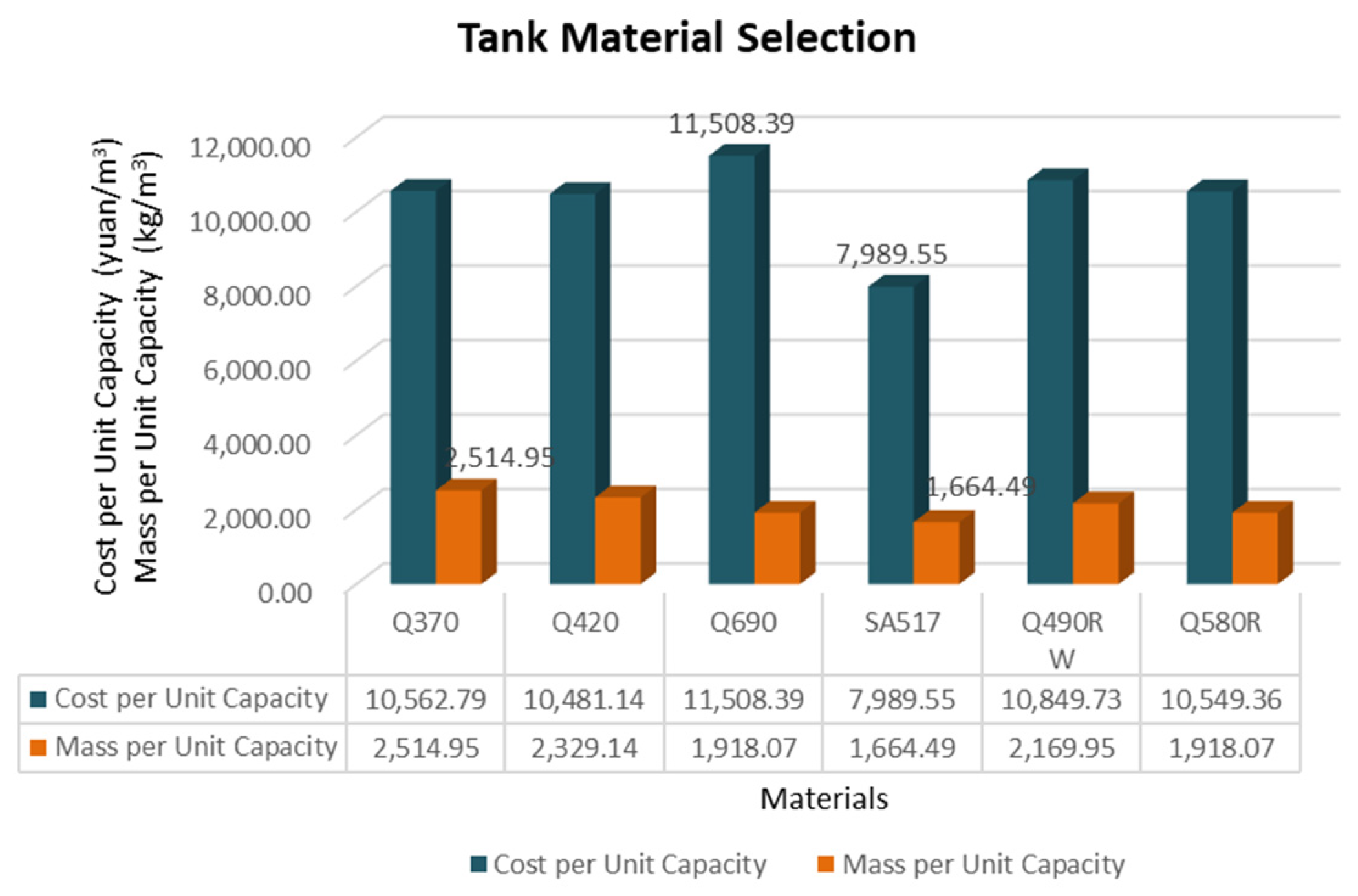
3.2.1. Comparison Parameters

In this paper, the following two economic parameters need to be introduced to the design of CO2 storage unit size:
  • Cost per Unit Capacity: the cost of tank construction and operation per unit of storage capacity.
  • Mass per Unit Capacity: the mass of the tank per unit capacity.
The calculation of these two parameters is governed by Equations (1) and (2):
Cost per Unit Capacity = P × (M1 + M2 × a)/(V1 + V2)
Mass per Unit Capacity = ρ × (M1 + M2)/(V1 + V2)
where: P is the Unit price of steel materials (yuan: CNY currency); M1 is the quality of the cylinder; M2 is the quality of storage tank heads; M1 is the volume of the cylinder; M2 is the volume of storage tank heads; a is the price cost factor of tank heads; ρ is the density of steel.
The cost per unit capacity directly affects the CO2 storage cost and thus the overall operating cost of the ship, the weight per unit capacity takes up the effective cargo capacity of the ship and affects the operating income of the ship, and a larger weight per unit capacity will increase the resistance of the ship’s voyage and increase the cost of fuel consumption, so it is hoped that, under the premise of guaranteeing the safe storage of CO2, and by taking into account the material of the storage tanks, the strength of the materials, the price, and other factors, it is possible to measure the following Minimum unit capacity cost and unit capacity weight.

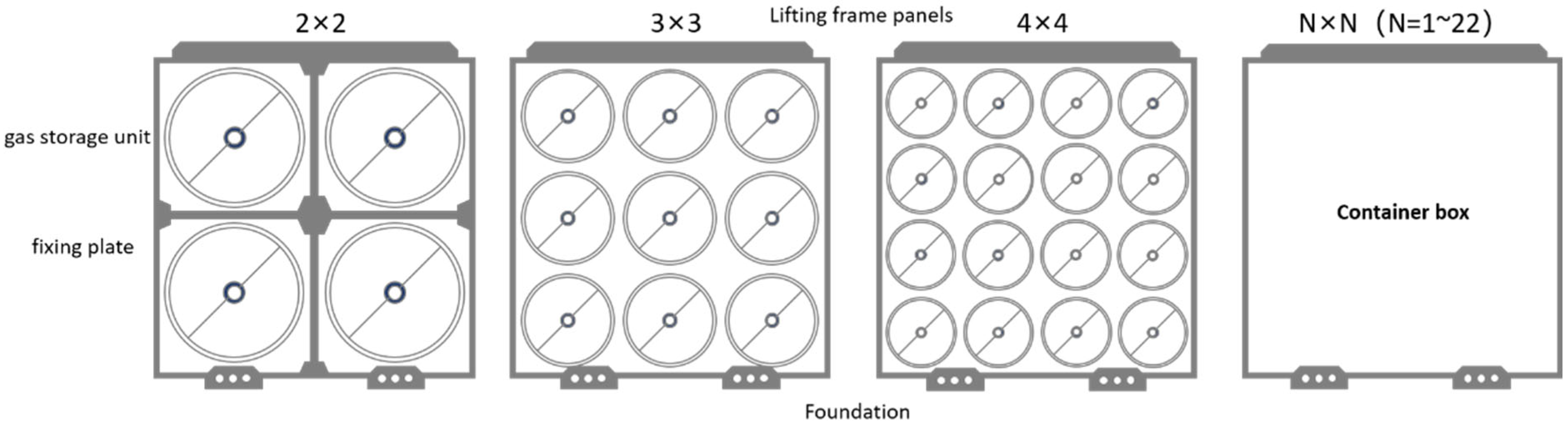
3.2.2. Comparison Results and Explanation of the Layout of CO2 Storage Units

  • Comparison of materials for CO2 storage unit
The vessel-wall thickness calculation is governed by Equation (3):
t = (P × R)/(σ × φ − 0.6 × P) + C
where: t is the wall thickness (mm); P is the design pressure (MPa); R is the inner radius of the container (mm); σ is the permissible stress of the material (MPa) determined by the material properties and operating temperatures; φ is the coefficient of welded joints (no welding is 1, welded joints are usually 0.85~1.0); 0.6P is the pressure correction; C is the corrosion margin (mm).
Taking into account the fluctuations and differences in international steel market prices, we have selected the Chinese steel market in Asia as the focus of our recent market research. A comprehensive market survey was conducted on six candidate tank materials—Q370, Q420, Q690, SA517, Q490RW, and Q580R [99,100,101]—encompassing parameters such as price, tensile strength, density, and yield strength. The findings are tabulated in Table 5. Preliminary analysis indicates that the SA517 model exhibits the optimal cost-performance ratio, although detailed engineering calculations remain imperative before finalizing the material selection.
The same design constraints (pressure, geometry, temperature) were applied to the six aforementioned steel materials and the Cost per Unit Capacity and Mass per Unit Capacity were calculated for all materials using Equations (1)–(3). As illustrated in Figure 15, SA517-grade steel exhibits a Cost per Unit Capacity of 7989.55 yuan/m3 and a Mass per Unit Capacity of 1664.49 kg/m3—both representing the lowest values among the materials. This demonstrates its exceptional economic performance relative to other options. Consequently, the subsequent design of the CO2 storage tank in this paper will select SA517 for further optimization, including layout design.
  • CO2 storage unit size (diameter, height) design comparison
This study proposes the integration of compact CO2 storage units within standardized containers. The design process prioritizes spatial configuration (horizontal and vertical orientation) and modular scalability to optimize container utilization. Using standardized containers as modular frameworks, cost-effectiveness metrics were evaluated across varying layouts and unit dimensions. This analysis identified the optimal CO2 storage unit size, balancing structural efficiency and economic viability.
Horizontal Layout: Assuming a working pressure of 7 MPa and a maximum design pressure of 7.35 MPa, the CO2 storage units are arranged in a horizontal grid configuration. Each unit is equipped with hemispherical headers of uniform dimensions at both ends. To identify the optimal design scheme, we evaluate and optimize the number of storage units, the inner and outer diameters of the tanks, and the length of the cylindrical body. This optimization is conducted for two standard container sizes (20-inch and 40-inch), with a focus on minimizing both the cost per unit capacity and the mass per unit capacity.
The optimization calculation results are visualized in Figure 16. Under the specified conditions and horizontal network configuration, the most economically efficient layout for the 20-inch container is a 3 × 3 arrangement of CO2 storage units, each with a diameter of 690 mm and a cylindrical height of 4700 mm. In contrast, for the 40-inch container, a 2 × 2 arrangement with a unit of 1030 mm in diameter and 4300 mm in cylindrical height is both safer and more cost-effective. Overall, the 2 × 2 ( ϕ : 1030 mm, H: 4300 mm), 3 × 3 ( ϕ : 690 mm × H: 4700 mm), and 4 × 4 ( ϕ : 510 mm × H: 4800 mm) configurations are considered the most reasonable layout options based on a balance of safety and economic performance.
Vertical Placement: Assuming a working pressure of 7 MPa and a maximum design pressure of 7.35 MPa, the CO2 storage units are arranged in a single-layer vertical configuration. Each unit is designed with a hemispherical head at the top and a flat bottom. To determine the optimal design scheme, we optimize the number of storage units, the inner and outer diameters of the tanks, and the length of the cylindrical body. This optimization is carried out for two standard container sizes (20-inch and 40-inch), with consideration given to two key performance indicators: tank mass per unit capacity and tank cost per unit capacity.
The optimization results are presented in Figure 17. Under the specified conditions, the most favorable outcome is achieved with CO2 storage units having a diameter of 690 mm and a cylindrical height of 1455 mm, arranged in a single vertical layer of 16 units. Alternative configurations—such as units with a diameter of 1030 mm and a cylindrical height of 1285 mm (10 units), or units with a diameter of 510 mm and a cylindrical height of 1545 mm (21 units)—yield slightly less optimal, yet still viable, economic performance.

3.2.3. Case Analysis

Through comprehensive market research and database queries [102,103,104,105], this study has compiled many existing ship data and operational insights—encompassing ship tonnage, energy consumption, average daily CO2 emissions, standard container capacity, and voyage duration—to establish the parameter specifics of the ocean-going vessel X, as tabulated in Table 6. These data facilitate the calculation and comparison of different CO2 storage schemes for the vessel.
Taking into account the target CO2 avoidance rate (set at 30%) and a voyage duration of 20 days, it is necessary to store a minimum of 8347 tons of CO2. For each scheme, the CO2 storage temperature and pressure are specified, followed by calculating the storage density using the CO2 phase diagram (These calculations are supported by REFPROP [106], a mature thermodynamic and transport property calculation software developed by the National Institute of Standards and Technology (NIST) of the United States. Widely adopted in both industry and academia, this software is used to calculate and predict the thermodynamic properties of various working fluids, encompassing physical properties, thermodynamic properties, and transport properties). Finally, the required CO2 storage space for each scheme is derived from fundamental mass-volume formulas. Three existing design options are considered, and the calculation basis and results for each are presented below in Equation (4) and Table 7.
Annual DWT (Deadweight Tonnage) loss cost:
C l o s t = T E U × ρ × c T E U l o s t × φ
where: TEU represents the total container capacity of the vessel; ρ denotes the loss rate of deadweight tonnage; C T E U l o s t is the cost of lost cargo space (according to Korberg [36], the value of 900 EUR/TEU/trip was obtained in this case); and φ indicates the frequency of the liner’s voyages per year ( φ = 20 in this case).
As shown in Table 7, with the same CO2 storage capacity (8347 tonnes), this case compares three different CO2 storage units: a large C-Tank, an individual containerized tank, and a storage unit system within containers.
  • C-Tank: Due to its large dimensions, this tank must be pre-installed at a designated hull position, leading to significant deadweight tonnage loss. In the early stage of CO2 storage, substantial free space exists inside the tank, resulting in an additional container space occupancy rate of 7.61%. The annual cost of deadweight tonnage loss amounts to USD 12,191,220.
  • Individual Containerized Tank: Calculations show that 406 TEU tanks meet the total CO2 storage requirement, with an additional space occupancy rate of 4.56%. The annual cost of lost deadweight ton is USD 7,305,120.
  • Small Storage Units in Containers: Due to the more efficient use of container space, 320 TEU with small storage units satisfy the storage requirement, achieving an additional space occupancy rate of only 3.6%. The annual deadweight tonnage loss cost is USD 5,767,200.
Comparisons have shown that the small CO2 storage units system proposed in this study, integrated into standard-size containers, demonstrates a significantly lower additional occupancy rate and deadweight loss cost compared to the C-Tank. Specifically, its annual cost of lost deadweight ton is 52.2% lower than the C-Tank, highlighting its economic superiority.
Furthermore, these small-sized storage units provide other operational advantages, such as easier lifting and unloading during docking, enabling more flexible and timelier reallocation of cargo space.

3.3. Advantage: Small Size CO2 Storage Unit Group Design

  • High use flexibility: By reducing the tank diameter, a higher-pressure design is achieved, enabling the device to safely store CO2. Compared to conventional large-diameter CO2 storage tanks, the system offers more stable and reliable pressure-bearing performance, effectively mitigating safety risks associated with stress concentration within the tank structure. Additionally, the number of CO2 storage units can be flexibly adjusted, allowing the system to be optimized based on actual gas pressure and phase transitions.
  • Efficient space utilization and convenient transportation: Multiple CO2 storage units are integrated into standard containers, optimizing the use of container space, enabling a compact layout, and enhancing space utilization. The standard container design also facilitates lifting and transportation, making full use of existing logistics and transportation networks and infrastructure. This design enables efficient transfer, thereby improving equipment mobility and adaptability.
  • Almost no downtime maintenance period: In the event of a failure of an individual container CO2 storage unit, it can be bypassed, allowing continued operation with minimal disruption. The equipment maintenance time is extremely short, making it more convenient compared to traditional large CO2 storage tanks. Additionally, this design has almost no impact on the vessel’s normal navigation, CO2 capture, or storage operations.

4. Discussion

This subsection critically examines unresolved technical and operational challenges in maritime CCUS systems, including practical implementation constraints and design compatibility, safety and environmental risks of onboard CO2 storage, CO2 offloading logistics, infrastructure, and risks, empirical economic data and feasibility analysis, advantages and disadvantages of modality, regulatory framework and incentives, and integration with broader decarbonization strategies.

4.1. Practical Implementation Constraints and Design Compatibility

Deploying CCUS on ships poses significant practical challenges [107] that must be addressed in design and operation. Key constraints include:
  • Space and Weight Limitations: Onboard space and deck area is limited, installing CCUS unit can encroach on cargo holds or deck area, especially in retrofits. Careful naval architecture assessments are needed to integrate the CCUS system without exceeding stability and strength limits. Newbuild designs can plan for this from the beginning, whereas retrofitting existing ships is far more challenging, requiring creative use of available spaces and perhaps relocating or upgrading other equipment to make room.
  • Power and Utility Integration: CO2 capture systems demand considerable energy and utility support (steam, cooling water, electricity, etc.). The ship’s existing engines and generators must accommodate the parasitic load of carbon capture. These integration issues mean that comprehensive engineering and possibly engine re-tuning are needed when retrofitting CCUS.
  • Operational Complexity and Crew Training: Crew members will need to learn the normal operation of the capture plant, routine maintenance, such as replacing filters or membranes, and respond to emergencies such as leaks or high CO2 levels. Updating safety procedures and documentation is essential for safe operation
  • Regulatory and Classification Compliance: Since regulations and classification standards are still catching up, shipowners may be reluctant to invest without assured compliance pathways. The ongoing development of IMO’s framework is expected to provide more clarity in the near future.
By recognizing and addressing these practical constraints—spatial, integrational, human, and regulatory—designers can better ensure that shipboard CCUS systems are compatible with vessel operations. Early pilots have highlighted these issues. For instance, the K-Storm project [108] aims to minimize onboard modifications by using self-contained modules. Despite these challenges, a small number of ships are already running CCUS systems safely, thanks to comprehensive training and risk management practices.

4.2. Safety and Environmental Risks of Onboard CO2 Storage

Storing CO2 onboard at high-pressure and low temperature introduces specific safety and environmental risks. There is an explosion risk associated with pressurized CO2 tanks. Therefore, tanks must have over-pressure protection such as pressure relief valves or rupture discs. CO2 is also odorless, colorless, and an asphyxiant gas. A leak in an enclosed compartment could quickly create a life-threatening atmosphere. Thus, crew training on CO2 leak response is critical. As discussed, pure CO2 has the peculiarity of a triple point at 5.17 bar, –56.6 °C [109]. When the storage tank or associated piping falls below these conditions, dry ice will form. Solid CO2 can cause blockages in valves or lines and can also lead to pressure spikes as it warms and re-sublimates in confined spaces. Even though CO2 is not toxic, a sudden large release in port or an enclosed waterway could lower air quality and, if it dissolves, locally acidify the water.
Overall, the storage of CO2 on ships demands engineering and operational controls comparable to those for LPG/LNG carriers, with knowledge on the unique properties of CO2. Although formal regulations are still in development, industry consensus holds that onboard CO2 storage risks can be managed to an acceptable level, analogous to other hazardous cargoes.

4.3. CO2 Offloading Logistics, Infrastructure, and Risks

Once CO2 is captured onboard, a critical challenge is how to offload and handle the CO2 at port. The current infrastructure at ports worldwide is largely inadequate to receive and manage captured CO2 in large quantities. A recent joint study by the Global Centre for Maritime Decarbonisation (GCMD) [110], Lloyd’s Register and others identified low port readiness as a major bottleneck to the adoption of onboard carbon capture. While the technologies for transferring liquid CO2 exist, safe and efficient operational procedures have not yet been demonstrated at scale. As shown in Figure 18, there are a few pathways for offloading captured CO2 from a vessel:
  • Ship-to-Shore: The ideal scenario is a ship arriving at a port equipped with a CO2 reception facility. The vessel would connect to a shore-based tank via insulated cryogenic transfer hoses or loading arms. However, only a few ports involved in pilot projects are installing the refrigerated storage tanks, vaporizers, and pumps needed. Most ports do not have plans to install shore-based tanks until upstream supply and downstream subsurface or usage is clear. Shipowners are depending on a developed discharging network for their onboard CCUS installation.
  • Ship-to-Ship: Another approach is transferring the CO2 to a smaller shuttle vessel or barge outfitted to carry LCO2, which then delivers it to a storage hub. This avoids complicated terminal retrofits at every port and instead relies on a few CO2 aggregation vessels shuttling to sequestration sites. This study ranked ship-to-ship and ship-to-shore via an intermediary vessel as the top options for scaling up offloading, since they reduce port-side bottlenecks.
  • Containerized (ISO Tank) Offloading: In this approach, captured CO2 is liquefied onboard and pumped into portable tank containers (usually 20- or 40-foot ISO tanks) which are then landed by crane at port and transported by truck or rail. This method is highly flexible and leverages existing container logistics, requiring minimal new infrastructure at the port aside from perhaps a refrigeration hookup to keep the CO2 cold. It is already in use in one system: the Value Maritime OCCS [111], which fills a swap-out CO2 absorption cartridge that is simply offloaded at port.
In any offloading scenario, infrastructure for onward transport or storage of the CO2 is vital. The GCMD survey of planned CO2 hubs worldwide shows that port infrastructure for handling CO2 must be scaled up along with these projects to achieve economies of scale. Until large storage or utilization sites are operational, ships might be limited to discharging at a few specialized ports (e.g., terminals associated with carbon storage projects in the North Sea or Gulf of Mexico [112,113]).
Despite these challenges, some early operations have been successful. Notably, in 2024, Evergreen Marine reported [114] that its 14,000 TEU Ever Top containership offloaded captured CO2 to a shore facility for reuse, and was able to deduct this CO2 from its emissions for IMO Carbon Intensity rating purposes. CO2 offloading is currently a weak link in CCUS chain, but initiatives are underway to close this gap by building infrastructure and establishing safe operating guidelines.

4.4. Empirical Economic Data and Feasibility Analysis

A crucial aspect of onboard CCUS is its economic viability. At the current stage, empirical data is limited to pilot projects and techno-economic studies, but these provide valuable insights. Generally, onboard carbon capture is found to increase fuel consumption, energy penalty and entail high capital and operating costs, leading to a significant cost per tonne of CO2 emission reduced. Here, we compile data from recent projects and studies to quantify these trade-offs.
In Table 8, Stena Impero Pilot (REMARCCABLE Project) [115] is a First-of-a-kind retrofit pilot; relatively high abatement cost due to pioneering nature and small-scale demonstration. Costs are expected to decrease significantly with larger scale and standardization. VLCC Newbuild [116] Study completed theoretical analysis projecting cost efficiencies for large-scale implementation; cost per ton significantly reduced due to economies of scale and optimized ship integration. Wärtsilä OCCS System [117] (Clipper Eris) reported significantly lower estimated abatement costs through industrial scaling and optimized integration; limited detailed financial data publicly disclosed. Value Maritime [111] Modular System compact modular solution targeting small ships, offering low complexity and minimal integration challenges, though detailed economic data remain limited.
The REMARCCABLE engineering study (2024) [122] retrofitted a carbon capture system on the medium-range tanker Stena Impero. The calculated abatement cost for this prototype was approximately USD 769 per tonne of CO2. This figure is high—by comparison, many shore-based industrial CCS projects target costs in the USD 50–150/ton range—reflecting the early stage and small-scale of maritime CCUS.
At a different scale, a scenario analysis by the Mærsk Mc-Kinney Møller Center (2022) [123] found that for a VLCC newbuild, which can more easily accommodate a large capture system, the CO2 abatement cost could range USD 220–290 per ton for ~75% net emissions reduction. This result brings CO2 capture into a range where a combination of carbon pricing and efficiency gains could make it viable.
Beyond the capital expenditure of installing the equipment, operating costs can be significant. Major components of OPEX for an onboard capture system should include fuel penalty, solvent and consumables, maintenance and crew labor, CO2 offloading and logistics.
Overall, current empirical data indicate that shipboard CCUS is technically feasible but economically challenging today. The cost per ton of CO2 is presently high, but there is a credible trajectory for cost reduction. Key to improving economics will be scaling up system size, optimizing current system, introducing new approaches with efficiency advantages, such as Modular systems.

4.5. Trade-Offs and Design Considerations for Modular CCUS Systems

Modular ship CCUS systems package the capture equipment into compact units that can be more easily installed, removed, or scaled. This approach offers clear benefits for retrofitting, flexibility and cost reduction, but it also comes with trade-offs in performance and ship integration. Here, we discuss the implications of modular design versus fully integrated design.
  • Ease of Retrofit and Installation: Modular CCUS units are typically self-contained skids that can be fabricated and tested onshore, then lifted onto the vessel.
  • Cost Considerations: Modular units, especially if containerized, open up the possibility of manufacturing in series, turning CO2 capture systems into a commodity that can be produced in factories at lower unit cost. This could drive down prices significantly if demand scales up.
  • Deadweight tonnage consumption: Traditional systems are bulky with irregular shapes, often featuring tall towers or tanks. In contrast, modular container-integrated capture systems offer greater practicality and are often preferred by cost-conscious shipowners.
  • Performance and Efficiency: A potential drawback of self-contained modular systems is that they might not be as optimized or efficient as a fully integrated system. For example, a containerized capture module might carry its own small CO2 compressor and chiller powered by an independent diesel genset or the ship’s electrical grid, rather than tapping directly into the ship’s main engine waste heat or excess steam.
  • Operational management flexibility: A modular system’s failure affects only part of the capture capacity, whereas a single integrated system is a single point of failure for capture functionality. This redundancy aspect may make modular attractive for reliability.
The industry is currently experimenting with both approaches. Clipper Eris (Sol-vang/Wärtsilä) [120] represents an integrated retrofit. In contrast, K-Storm (Crow-ley/Carbon Ridge) is a clear modular retrofit, aiming for minimal ship impact and easy installation [124]. Another example, Eastern Pacific Shipping’s tanker Pacific Cobalt, will use a Value Maritime module, essentially bolting on a prefabricated capture and filter unit to achieve about 40% CO2 capture [125]. This is low-hanging fruit—it may not maximize capture, but its relatively low complexity.

4.6. Regulatory Framework and Incentives (IMO, EU ETS, Etc.)

The regulatory landscape for shipping CCUS is rapidly evolving, as international and regional bodies recognize the need to accommodate and encourage carbon capture in maritime decarbonization.

4.6.1. IMO’s Developing Framework

At present, there are no explicit IMO rules that either mandate or comprehensively regulate onboard carbon capture systems. However, the IMO has moved quickly in the past two years to acknowledge OCCS. In 2021–2023, various IMO committees (MPC, MSC) began discussions on how to handle novel GHG reduction methods, including CCUS. Most significantly, in April 2025 during MEPC 83, the IMO approved a work plan to develop a full regulatory framework for onboard carbon capture and storage [126]. Also, the IMO’s Working Group on GHG has been tasked to figure out how to account for captured CO2 in the IMO DCS (Data Collection System) [127] and CII (Carbon Intensity Indicator) schemes [128]. By around 2028, the IMO is expected to roll out: safety guidelines and accounting mechanisms so that captured CO2 can be deducted from a ship’s reported emissions. Already, IMO’s revised GHG Strategy (2023) [129] includes “mid-term measures should encourage innovation like CCUS”, viewing it as a complementary measure alongside alternative fuels. This top-level recognition means any carbon pricing or fuel standard the IMO implements could include credits for OCCS [130].

4.6.2. EU Regulations—Emissions Trading System (ETS)

The EU has been more immediately prescriptive by extending its Emissions Trading System to shipping. From 2024, large ships must account for their CO2 emissions on voyages to, from, and between EU ports, and surrender carbon allowances accordingly [130]. ETS creates a direct monetary incentive: every tonne of CO2 one can legally declare as captured and stored saves the cost of an allowance [130]. It is important that the infrastructure to realize this must exist, and the EU recognizes this and is funding CO2 transport and storage projects that could interface with shipping.
Moreover, Norway has its own aggressive climate targets and is currently funding pilots like Clipper Eris. The UK is considering how to treat captured CO2 in its MRV system. In absence of full regulations, classification societies and some flag administrations are issuing interim standards. Lloyd’s Register’s first OCCS class notation shows that class can formalize requirements for construction and trials [131]. ABS has released guide-lines on safety and is likely to offer similar notations. Amendments in 2009 to the London Protocol now also allow cross-border transport of CO2 for the purpose of geological storage [132]. All these effort supports the improvement of CO2 credit mechanisms and economic incentive systems.

4.7. Integration with Broader Decarbonization Strategies

The IMO’s 2050 goals cannot be met by one technology alone, which needs to combine CCUS with other measures, such as alternative fuels, energy efficiency, operational changes, and possibly carbon offsetting. In this section, we discuss how onboard CCUS can integrate with and complement other decarbonization approaches for ships.

4.7.1. Bridge Strategy: Complementary to Alternative Fuels

The industry is exploring new fuels like LNG, methanol, ammonia, hydrogen, biofuels, etc., each with pros and cons. While fuels like green ammonia and hydrogen could eventually become the best zero-carbon options, building the necessary production and fueling infrastructure will take time and heavy investment. Meanwhile, ships can still run on traditional fuels or a mix of fuels, using CCUS technology to trap the CO2 emissions. This ‘bridge’ approach helps reduce emissions early on without waiting for the perfect fuel. Industry experts recognize that adding CCUS to existing ships is a smart way to cut emissions now, whereas many alternative fuels are more suited for new ships or vessels that can be converted. For example, installing CCUS on current ships now can help meet 2030 emission goals, with plans to retire or upgrade these ships to zero-emission vessels by 2035.

4.7.2. Integrate with Efficiency Measures

Energy efficiency measures will reduce the amount of fuel burned and hence CO2 produced through better hull designs, propulsion improvements, wind-assisted devices, speed optimization, etc. Reducing the amount of exhaust CO2 helps lighten the load on a CCUS system. When there is less CO2 to capture, a smaller or less powerful system might do the job, or the existing one could run more efficiently, saving energy. In practice, shipowners will likely do both: take steps to improve fuel efficiency and use CCUS to catch most of the remaining CO2. Combining these approaches can lead to bigger reductions than doing either alone. Also, slowing down the ship means less exhaust flow and potentially cooler exhaust. This might make capturing CO2 easier because the gas stays in the absorber longer, and waste heat could be more readily available relative to engine output.

4.7.3. Integrate with Operational Strategies

If carbon costs are introduced, an operator might do cost-optimization: only capture CO2 until the marginal cost of capture equals the levy cost of emitting. Basically, they would only capture CO2 until the expense of capturing equals what they would pay if they emitted it anyway. Think of it like how power plants sometimes only run carbon capture systems when carbon prices are high. In a broader strategy, using CCUS becomes just one of several tools to control emissions—alongside things like scheduling when and where they operate, choosing routes that avoid high-emission areas, and other operational decisions.

4.7.4. Integrate with Infrastructure and End-Use Integration

If ports develop CO2 utilization hubs, then a ship capturing CO2 essentially becomes part of a larger carbon circular economy. This synergy amplifies the impact of CCUS beyond just the ship itself and could attract cross business investment.
In summary, using onboard carbon capture alongside other strategies like switching to alternative fuels, improving energy efficiency, making operational tweaks, and possibly offsetting carbon is the way forward. The key here is combining these methods because ships are complex systems, and decarbonization is not just about one fix. As industry rules and regulations become clearer and more established, industry players can find the best mix of solutions that work for their circumstances.

5. Conclusions

Global carbon emission reduction efforts are increasing, shipping as one of the important sources of carbon emissions, there is an urgent need for technological upgrading in response to the IMO and other international organizations to reduce emissions targets, OCCS technology came into being, this paper focuses on the existing two major problems of OCCS technology, capture equipment and CO2 storage device to design technology upgrades to provide design assistance for the eventual formation of OCCS batch standardized equipment industry chain. The key contributions of this paper are summarized as follows:
(1)
This paper designs a “modular OCCS device”, which is more flexible to meet the emission reduction demand and process flexibility adjustment of such mobile carbon sources as ships. Modular design of standardized parts improves the adaptability of OCCS to different flue gas flow rates and working conditions. The series-parallel assembly method is convenient to meet the requirements of incoming gas volume and working conditions, and facilitates the installation, maintenance, upgrading and use in various scenarios, thus reducing the cost of industrial production in the long run.
(2)
This paper breaks the cost limitation of low-pressure storage of CO2 in ships by designing a “small-size CO2 storage units” that can be loaded into a standard container, and improves high-pressure storage safety with guaranteed economy. Adopting standard container box as the outer frame instead of traditional large-size storage tanks, it can realize universal transportation, rapid deployment and flexible deployment of quantity, and meet the requirements of different CO2 storage volume and gas pressure phase state. Considering the material cost, pressure strength, weight and other factors of the CO2 storage device, we introduce the two core parameters of “cost per unit capacity” and “mass per unit capacity” to compare the design of different materials and sizes of the CO2 storage unit, and finally calculate the safest and most economical size of the CO2 storage unit.
(3)
When the CO2 storage units are arranged in a horizontal grid configuration, the 2 × 2 ( ϕ : 1030 mm, H: 4300 mm), 3 × 3 ( ϕ : 690 mm × H: 4700 mm), and 4 × 4 ( ϕ : 510 mm × H: 4800 mm) configurations are considered the most reasonable layout options based on a balance of safety and economic performance. When the CO2 storage units are arranged in a single-layer vertical configuration, the most favorable outcome is achieved with CO2 storage units having a diameter of 690 mm and a cylindrical height of 1455 mm.
Future work will report the experimental validation results, including system operational stability, capture rate, and membrane optimization strategies, in a dedicated follow-up paper referencing this foundational design study.
In addition, this paper thoroughly discusses unresolved technical and operational challenges in maritime CCUS systems. In summary, the design proposed in this paper demonstrates theoretical innovativeness and offers practical inspiration for advancing green ship carbon reduction technologies. As for how the CO2 captured by ships can be properly disposed of, how to ensure that it is no longer released into the atmosphere, and how to achieve the most convenient and efficient storage and resource utilization should be given enough attention. It is believed that under the background of green ship, CCUS technology will be used in synergy with other ship emission reduction technologies, and make a bottom-up guarantee for carbon emission reduction of ships.

Author Contributions

Conceptualization, N.Z. and X.L.; methodology, N.Z. and X.L.; validation, C.W., Z.P., Y.C., L.L., L.C., J.H. and W.W.; writing—original draft preparation, N.Z., X.L. and X.W.; writing—review and editing, N.Z., X.L. and X.W.; visualization, N.Z., C.W. and Z.P.; supervision, X.L., C.W. and W.W. All authors have read and agreed to the published version of the manuscript.

Funding

This research was supported by the Key R&D Program of Shandong Province, China (2022CXGC020303).

Data Availability Statement

The original contributions presented in this study are included in the article. Further inquiries can be directed to the corresponding author.

Conflicts of Interest

Authors Youxiao Chen, Lianhao Liu and Lijie Chen are employed by the company CIMC Offshore Co., Ltd. The remaining authors declare that the research was conducted in the absence of any commercial or financial relationships that could be construed as a potential con-flict of interest.

Abbreviations

The following abbreviations are used in this manuscript:
CCUSCarbon dioxide Capture, Utilization and Storage
OCCSOnboard Carbon Capture Systems
LNGLiquefied Natural Gas
TEUTwenty-Foot Equivalent Unit
DWTDeadweight Tonnage

References

  1. Crippa, M.; Guizzardi, D.; Banja, M.; Solazzo, E.; Muntean, M.; Schaaf, E.; Pagani, F.; Monforti-Ferrario, F.; Olivier, J.; Quadrelli, R.; et al. CO2 Emissions of All World Countries. JRC Publications Repository. Available online: https://publications.jrc.ec.europa.eu/repository/handle/JRC130363 (accessed on 28 April 2025).
  2. Chen, S.; Miao, C.; Zhang, Q. Understanding the Evolution of China’s Green Shipping Policies: Evidence by Social Network Analysis. J. Clean. Prod. 2024, 482, 144204. [Google Scholar] [CrossRef]
  3. IEA. Global CO2 Emissions from Energy Combustion and Industrial Processes and Their Annual Change, 1900–2023—Charts—Data & Statistics. Available online: https://www.iea.org/data-and-statistics/charts/global-CO2-emissions-from-energy-combustion-and-industrial-processes-and-their-annual-change-1900-2023 (accessed on 1 May 2025).
  4. IEA. CO2 Emissions in 2023—Analysis. Available online: https://www.iea.org/reports/CO2-emissions-in-2023 (accessed on 28 April 2025).
  5. Luo, X.; Wang, M. Study of Solvent-Based Carbon Capture for Cargo Ships through Process Modelling and Simulation. Appl. Energy 2017, 195, 402–413. [Google Scholar] [CrossRef]
  6. Fourth Greenhouse Gas Study 2020. Available online: https://www.imo.org/en/OurWork/Environment/Pages/Fourth-IMO-Greenhouse-Gas-Study-2020.aspx (accessed on 28 April 2025).
  7. Wang, Y.; Cao, Q.; Liu, L.; Wu, Y.; Liu, H.; Gu, Z.; Zhu, C. A Review of Low and Zero Carbon Fuel Technologies: Achieving Ship Carbon Reduction Targets. Sustain. Energy Technol. Assess. 2022, 54, 102762. [Google Scholar] [CrossRef]
  8. OECD. CO2 Emissions from Global Shipping. Available online: https://doi.org/10.1787/bc2f7599-en (accessed on 1 May 2025).
  9. Review of Maritime Transport 2024 | UN Trade and Development (UNCTAD). Available online: https://unctad.org/publication/review-maritime-transport-2024 (accessed on 1 May 2025).
  10. Green Shipping: Innovations, Strategies, And Trends. Available online: https://www.gocomet.com/blog/what-is-green-shipping/ (accessed on 24 May 2025).
  11. Green Ship: Green Technologies in Shipping Industry. Available online: https://marine-digital.com/article_green_ship (accessed on 24 May 2025).
  12. IEA. CO2 Emissions from Energy Combustion and Industrial Processes, 1900–2021—Charts—Data & Statistics. Available online: https://www.iea.org/data-and-statistics/charts/CO2-emissions-from-energy-combustion-and-industrial-processes-1900-2021 (accessed on 1 May 2025).
  13. Joung, T.-H.; Kang, S.-G.; Lee, J.-K.; Ahn, J. The IMO Initial Strategy for Reducing Greenhouse Gas(GHG) Emissions, and Its Follow-up Actions towards 2050. J. Int. Marit. Saf. Environ. Aff. Shipp. 2020, 4, 1–7. [Google Scholar] [CrossRef]
  14. DNV. Nordic Roadmap Conference Brings Together Partners to Accelerate Decarbonization Through Green Shipping Corridors. Available online: https://www.dnv.com/news/nordic-roadmap-conference-brings-together-partners-to-accelerate-decarbonization-through-green-shipping-corridors-235672/ (accessed on 24 May 2025).
  15. Tiuttu, T.-A. Green Shipping: What It Is & Why Is It Important. SDG Monitor. Available online: https://www.sdgmonitor.co/post/green-shipping-what-it-is-why-is-it-important (accessed on 24 May 2025).
  16. World Economic Forum. Green Infrastructure Can Protect Ports from Growing Environmental Risks. Here’s How. Available online: https://www.weforum.org/stories/2022/08/ports-green-infrastructure-environmental-risks-climate/ (accessed on 24 May 2025).
  17. Future Fuels Nordic—A Nordic Roadmap for Introduction of Zero Emission Fuels in Shipping. Available online: https://futurefuelsnordic.com/ (accessed on 24 May 2025).
  18. Green Shipping Corridors. C40 Cities. Available online: https://www.c40.org/what-we-do/scaling-up-climate-action/ports-and-shipping/green-shipping-corridors/ (accessed on 24 May 2025).
  19. Announcements at COP29—Green Shipping Challenge. Available online: https://greenshippingchallenge.org/announcements-at-cop29/ (accessed on 24 May 2025).
  20. Hua, R.; Yin, J.; Wang, S.; Han, Y.; Wang, X. Speed Optimization for Maximizing the Ship’s Economic Benefits Considering the Carbon Intensity Indicator (CII). Ocean Eng. 2024, 293, 116712. [Google Scholar] [CrossRef]
  21. IMO Framework on Life Cycle GHG Intensity of Marine Fuels (LCA). Available online: https://www.imo.org/en/OurWork/Environment/Pages/Lifecycle-GHG---carbon-intensity-guidelines.aspx (accessed on 2 May 2025).
  22. Bilgili, L.; Ölçer, A.I. IMO 2023 Strategy-Where Are We and What’s next? Mar. Policy 2024, 160, 105953. [Google Scholar] [CrossRef]
  23. Reducing Emissions from the Shipping Sector-European Commission. Available online: https://climate.ec.europa.eu/eu-action/transport/reducing-emissions-shipping-sector_en (accessed on 2 May 2025).
  24. Xing, H.; Spence, S.; Chen, H. A Comprehensive Review on Countermeasures for CO2 Emissions from Ships. Renew. Sustain. Energy Rev. 2020, 134, 110222. [Google Scholar] [CrossRef]
  25. Melideo, D.; Desideri, U. The Use of Hydrogen as Alternative Fuel for Ship Propulsion: A Case Study of Full and Partial Retrofitting of Roll-on/Roll-off Vessels for Short Distance Routes. Int. J. Hydrog. Energy 2024, 50, 1045–1055. [Google Scholar] [CrossRef]
  26. Ustolin, F.; Campari, A.; Taccani, R. An Extensive Review of Liquid Hydrogen in Transportation with Focus on the Maritime Sector. J. Mar. Sci. Eng. 2022, 10, 1222. [Google Scholar] [CrossRef]
  27. Mao, X.; Ying, R.; Yuan, Y.; Li, F.; Shen, B. Simulation and Analysis of Hydrogen Leakage and Explosion Behaviors in Various Compartments on a Hydrogen Fuel Cell Ship. Int. J. Hydrog. Energy 2021, 46, 6857–6872. [Google Scholar] [CrossRef]
  28. Schwarzkopf, D.A.; Petrik, R.; Hahn, J.; Ntziachristos, L.; Matthias, V.; Quante, M. Future Ship Emission Scenarios with a Focus on Ammonia Fuel. Atmosphere 2023, 14, 879. [Google Scholar] [CrossRef]
  29. Fu, H.B.; Shang, G.F.; Lin, J.; Hu, Y.J.; Hu, Q.Q.; Guo, L.; Zhang, Y.C.; Chen, J.M. Fractional Iron Solubility of Aerosol Particles Enhanced by Biomass Burning and Ship Emission in Shanghai, East China. Sci. Total Environ. 2014, 481, 377–391. [Google Scholar] [CrossRef]
  30. Feng, Y.; Zhu, H.; Dong, Z. Simultaneous and Global Optimizations of LNG-Fueled Hybrid Electric Ship for Substantial Fuel Cost, CO2, and Methane Emission Reduction. IEEE Trans. Transp. Electrif. 2023, 9, 2282–2295. [Google Scholar] [CrossRef]
  31. Hwang, S.; Jeong, B.; Jung, K.; Kim, M.; Zhou, P. Life Cycle Assessment of LNG Fueled Vessel in Domestic Services. J. Mar. Sci. Eng. 2019, 7, 359. [Google Scholar] [CrossRef]
  32. Svanberg, M.; Ellis, J.; Lundgren, J.; Landälv, I. Renewable Methanol as a Fuel for the Shipping Industry. Renew. Sustain. Energy Rev. 2018, 94, 1217–1228. [Google Scholar] [CrossRef]
  33. Ushakov, S.; Stenersen, D.; Einang, P.M. Methane Slip from Gas Fuelled Ships: A Comprehensive Summary Based on Measurement Data. J. Mar. Sci. Technol. 2019, 24, 1308–1325. [Google Scholar] [CrossRef]
  34. Bicer, Y.; Dincer, I. Clean Fuel Options with Hydrogen for Sea Transportation: A Life Cycle Approach. Int. J. Hydrog. Energy 2018, 43, 1179–1193. [Google Scholar] [CrossRef]
  35. Rehbein, M.C.; Meier, C.; Eilts, P.; Scholl, S. Mixtures of Ammonia and Organic Solvents as Alternative Fuel for Internal Combustion Engines. Energy Fuels 2019, 33, 10331–10342. [Google Scholar] [CrossRef]
  36. Korberg, A.D.; Brynolf, S.; Grahn, M.; Skov, I.R. Techno-Economic Assessment of Advanced Fuels and Propulsion Systems in Future Fossil-Free Ships. Renew. Sustain. Energy Rev. 2021, 142, 110861. [Google Scholar] [CrossRef]
  37. Prussi, M.; Yugo, M.; De, P.L.; Padella, M.; Edwards, R.; Lonza, L. JEC Well-to-Tank Report v5; JRC Publications Repository; Publications Office of the European Union: Luxembourg, 2020. [Google Scholar]
  38. IPCC. Global Warming of 1.5°C: IPCC Special Report on Impacts of Global Warming of 1.5°C above Pre-Industrial Levels in Context of Strengthening Response to Climate Change, Sustainable Development, and Efforts to Eradicate Poverty, 1st ed.; Cambridge University Press: Cambridge, UK, 2022. [Google Scholar]
  39. Calvin, K.; Dasgupta, D.; Krinner, G.; Mukherji, A.; Thorne, P.W.; Trisos, C.; Romero, J.; Aldunce, P.; Barrett, K.; Blanco, G.; et al. IPCC, 2023: Climate Change 2023: Synthesis Report; Intergovernmental Panel on Climate Change (IPCC): Geneva, Switzerland, 2023.
  40. Sheng, X.; Lin, S.; Liang, W.; Xie, H.; Liu, M. Optimal Long-Term Planning of CCUS and Carbon Trading Mechanism in Offshore-Onshore Integrated Energy System. Appl. Energy 2025, 379, 124983. [Google Scholar] [CrossRef]
  41. Wu, H.; Zhang, X.; Wu, Q.; Zhou, X.; Yue, S. Readiness and Challenges of Carbon Capture Technologies Based on the Shipping Industry. Mar. Pollut. Bull. 2024, 207, 116878. [Google Scholar] [CrossRef]
  42. Wang, Z.; Lu, M.; Dong, S.; Tang, M.; Yan, X.; Li, K.; Yang, H. Study of Ship-Based Carbon Capture Optimization Considering Multiple Evaluation Factors and Main Engine Loads. J. Clean. Prod. 2024, 478, 143996. [Google Scholar] [CrossRef]
  43. Tsimplis, M.; Noussia, K. The Use of Ships within a CCUS System: Regulation and Liability. Resour. Conserv. Recycl. 2022, 181, 106218. [Google Scholar] [CrossRef]
  44. Zhao, T.; Li, R.; Zhang, Z.; Song, C. Current Status of Onboard Carbon Capture and Storage (OCCS) System: A Survey of Technical Assessment. Carbon Capture Sci. Technol. 2025, 15, 100402. [Google Scholar] [CrossRef]
  45. Stec, M.; Tatarczuk, A.; Iluk, T.; Szul, M. Reducing the Energy Efficiency Design Index for Ships through a Post-Combustion Carbon Capture Process. Int. J. Greenh. Gas Control 2021, 108, 103333. [Google Scholar] [CrossRef]
  46. Wang, H.; Zhou, P.; Wang, Z. Reviews on Current Carbon Emission Reduction Technologies and Projects and Their Feasibilities on Ships. J. Marine. Sci. Appl. 2017, 16, 129–136. [Google Scholar] [CrossRef]
  47. Wang, H.; Zhou, P.; Wang, Z. Experimental and Numerical Analysis on Impacts of Significant Factors on Carbon Dioxide Absorption Efficiency in the Carbon Solidification Process. Ocean Eng. 2016, 113, 133–143. [Google Scholar] [CrossRef]
  48. Fang, S.; Xu, Y.; Li, Z.; Ding, Z.; Liu, L.; Wang, H. Optimal Sizing of Shipboard Carbon Capture System for Maritime Greenhouse Emission Control. IEEE Trans. Ind. Appl. 2019, 55, 5543–5553. [Google Scholar] [CrossRef]
  49. Zhang, Y.; Xu, H.; Xu, J.; Zhang, X. Advancements and Challenges in Chemical Absorption Technologies for Shipborne Carbon Capture Applications: Absorbent Development, Improvement of Absorption Towers, and System Integration. J. Energy Chem. 2025, 106, 880–910. [Google Scholar] [CrossRef]
  50. Kotzampasakis, M. Maritime Emissions Trading in the EU: Systematic Literature Review and Policy Assessment. Transp. Policy 2025, 165, 28–41. [Google Scholar] [CrossRef]
  51. Oh, J.; Anantharaman, R.; Zahid, U.; Lee, P.; Lim, Y. Process Design of Onboard Membrane Carbon Capture and Liquefaction Systems for LNG-Fueled Ships. Sep. Purif. Technol. 2022, 282, 120052. [Google Scholar] [CrossRef]
  52. Buirma, M.; Vleugel, J.; Pruyn, J.; Doedée, V.; Schott, D. Ship-Based Carbon Capture and Storage: A Supply Chain Feasibility Study. Energies 2022, 15, 813. [Google Scholar] [CrossRef]
  53. García-Mariaca, A.; Llera-Sastresa, E. Review on Carbon Capture in ICE Driven Transport. Energies 2021, 14, 6865. [Google Scholar] [CrossRef]
  54. Awoyomi, A.; Patchigolla, K.; Anthony, E.J. Process and Economic Evaluation of an Onboard Capture System for LNG-Fueled CO2 Carriers. Ind. Eng. Chem. Res. 2020, 59, 6951–6960. [Google Scholar] [CrossRef]
  55. Feenstra, M.; Monteiro, J.; van den Akker, J.T.; Abu-Zahra, M.R.M.; Gilling, E.; Goetheer, E. Ship-Based Carbon Capture Onboard of Diesel or LNG-Fuelled Ships. Int. J. Greenh. Gas Control 2019, 85, 1–10. [Google Scholar] [CrossRef]
  56. Zhou, P.; Wang, H. Carbon Capture and Storage—Solidification and Storage of Carbon Dioxide Captured on Ships. Ocean Eng. 2014, 91, 172–180. [Google Scholar] [CrossRef]
  57. Güler, E.; Ergin, S. An Investigation on the Solvent Based Carbon Capture and Storage System by Process Modeling and Comparisons with Another Carbon Control Methods for Different Ships. Int. J. Greenh. Gas Control 2021, 110, 103438. [Google Scholar] [CrossRef]
  58. Wang, H. Analyzing the Current State and Future Development of Carbon Capture, Utilization and Storage (CCUS) Strategies and Technologies in China. J. Phys. Conf. Ser. 2023, 2608, 012061. [Google Scholar] [CrossRef]
  59. China Classification Society Releases ‘Shipping Low-Carbon Development Outlook 2023’. Available online: https://www.ccs.org.cn/ccswz/articleDetail?id=202312081257422748 (accessed on 1 May 2025).
  60. El-Kady, A.H.; Amin, M.T.; Khan, F.; El-Halwagi, M.M. Analysis of CO2 Pipeline Regulations from a Safety Perspective for Offshore Carbon Capture, Utilization, and Storage (CCUS). J. Clean. Prod. 2024, 439, 140734. [Google Scholar] [CrossRef]
  61. Vakili, S.; Manias, P.; Armstrong, L.-M.; Turnock, S.; Teagle, D.A.H. Technical, Economic, and Environmental Assessment of CO2 Ship Transport in Carbon Capture and Storage. J. Environ. Manag. 2025, 373, 123919. [Google Scholar] [CrossRef]
  62. Li, J. Accelerating the Offshore CCUS to Carbon-Neutral China. Fundam. Res. 2025, 5, 715–726. [Google Scholar] [CrossRef] [PubMed]
  63. Al Baroudi, H.; Awoyomi, A.; Patchigolla, K.; Jonnalagadda, K.; Anthony, E.J. A Review of Large-Scale CO2 Shipping and Marine Emissions Management for Carbon Capture, Utilisation and Storage. Appl. Energy 2021, 287, 116510. [Google Scholar] [CrossRef]
  64. Vessel Characteristics: Ship CLIPPER ERIS (LPG Tanker) Registered in Norway. Available online: https://www.marinetraffic.com/en/ais/details/ships/shipid:5868406/mmsi:257083750/imo:9834727/vessel:CLIPPER_ERIS (accessed on 26 May 2025).
  65. Vessel Characteristics: Ship STORM (Container Ship) Registered in Antigua Barbuda. Available online: https://www.marinetraffic.com/en/ais/details/ships/shipid:364287/mmsi:305350000/imo:9389435/vessel:STORM (accessed on 26 May 2025).
  66. GCMD. PROJECT REMARCCABLE (Realising Maritime Carbon Capture to Demonstrate the Ability to Lower Emissions). Available online: https://gcformd.cldy.asia/projects/project-remarccable/ (accessed on 26 May 2025).
  67. Lim, Y.K.; Lee, S.G.; Ko, M.; Park, K.; Lee, J.M. Operational Strategy of Pre-Cooling Process of CO2 Storage Tank in CCS Ship Transportation Using Model-Based Optimization. Chem. Eng. Res. Des. 2016, 109, 770–779. [Google Scholar] [CrossRef]
  68. Zhang, T.; Gao, H. Experimental investigation on performance of absorption refrigeration unit under ship swing condition. J. Eng. Thermophys. 2019, 40, 246–251. [Google Scholar]
  69. Visonà, M.; Bezzo, F.; d’Amore, F. Techno-Economic Analysis of Onboard CO2 Capture for Ultra-Large Container Ships. Chem. Eng. J. 2024, 485, 149982. [Google Scholar] [CrossRef]
  70. Seo, Y.; Huh, C.; Lee, S.; Chang, D. Comparison of CO2 Liquefaction Pressures for Ship-Based Carbon Capture and Storage (CCS) Chain. Int. J. Greenh. Gas Control 2016, 52, 1–12. [Google Scholar] [CrossRef]
  71. Sarbanha, A.-A.; Larachi, F.; Taghavi, S.-M.; Thiboutot-Rioux, M.; Boudreau, A.; Dugas, G. Mitigation of Ship Emissions: Overview of Recent Trends. Ind. Eng. Chem. Res. 2023, 62, 1707–1724. [Google Scholar] [CrossRef]
  72. Gan, L.; Che, W.; Zhou, M.; Zhou, C.; Zheng, Y.; Zhang, L.; Rangel-Buitrago, N.; Song, L. Ship Exhaust Emission Estimation and Analysis Using Automatic Identification System Data: The West Area of Shenzhen Port, China, as a Case Study. Ocean Coast. Manag. 2022, 226, 106245. [Google Scholar] [CrossRef]
  73. Chen, Y.-F.; Guo, N.; Wu, D.-S.; Hu, R. Numerical Investigation on Immiscible Displacement in 3D Rough Fracture: Comparison with Experiments and the Role of Viscous and Capillary Forces. Adv. Water Resour. 2018, 118, 39–48. [Google Scholar] [CrossRef]
  74. Vutukuru, S.; Dabdub, D. Modeling the Effects of Ship Emissions on Coastal Air Quality: A Case Study of Southern California. Atmos. Environ. 2008, 42, 3751–3764. [Google Scholar] [CrossRef]
  75. Corbett, J.J.; Fischbeck, P.S.; Pandis, S.N. Global Nitrogen and Sulfur Inventories for Oceangoing Ships. J. Geophys. Res. Atmos. 1999, 104, 3457–3470. [Google Scholar] [CrossRef]
  76. Eyring, V.; Köhler, H.W.; van Aardenne, J.; Lauer, A. Emissions from International Shipping: 1. The Last 50 Years. J. Geophys. Res. Atmos. 2005, 110, D17305. [Google Scholar] [CrossRef]
  77. Lauer, A.; Eyring, V.; Hendricks, J.; Jöckel, P.; Lohmann, U. Global Model Simulations of the Impact of Ocean-Going Ships on Aerosols, Clouds, and the Radiation Budget. Atmos. Chem. Phys. 2007, 7, 5061–5079. [Google Scholar] [CrossRef]
  78. Endresen, Ø.; Sørgård, E.; Behrens, H.L.; Brett, P.O.; Isaksen, I.S.A. A Historical Reconstruction of Ships’ Fuel Consumption and Emissions. J. Geophys. Res. Atmos. 2007, 112, D12301. [Google Scholar] [CrossRef]
  79. Endresen, Ø.; Sørgård, E.; Sundet, J.K.; Dalsøren, S.B.; Isaksen, I.S.A.; Berglen, T.F.; Gravir, G. Emission from International Sea Transportation and Environmental Impact. J. Geophys. Res. Atmos. 2003, 108, 4560. [Google Scholar] [CrossRef]
  80. Corbett, J.J.; Koehler, H.W. Updated Emissions from Ocean Shipping. J. Geophys. Res. Atmos. 2003, 108, 4650. [Google Scholar] [CrossRef]
  81. Qu, Z.; Kong, Z.; Yin, H.; Zhang, D.; Du, M. Study on carbon capture technology and development trend of exhaust gas from ocean-going ships. J. Environ. Eng. Technol. 2024, 14, 17–24. [Google Scholar]
  82. Carbon Dioxide Capture and Storage—IPCC. Available online: https://www.ipcc.ch/report/carbon-dioxide-capture-and-storage/ (accessed on 3 May 2025).
  83. Balcombe, P.; Brierley, J.; Lewis, C.; Skatvedt, L.; Speirs, J.; Hawkes, A.; Staffell, I. How to Decarbonise International Shipping: Options for Fuels, Technologies and Policies. Energy Convers. Manag. 2019, 182, 72–88. [Google Scholar] [CrossRef]
  84. Miller, D.C.; Litynski, J.T.; Brickett, L.A.; Morreale, B.D. Toward Transformational Carbon Capture Systems. AIChE J. 2016, 62, 2–10. [Google Scholar] [CrossRef]
  85. Rochelle, G.T. Amine Scrubbing for CO2 Capture. Science 2009, 325, 1652–1654. [Google Scholar] [CrossRef]
  86. Habibic, A. “World’s First” Ship with Full-Scale Onboard CCS Ready for Pilot Testing. Offshore Energy. Available online: https://www.offshore-energy.biz/worlds-first-ship-with-full-scale-onboard-ccs-ready-for-pilot-testing/ (accessed on 26 May 2025).
  87. Favre, E. Membrane Processes and Postcombustion Carbon Dioxide Capture: Challenges and Prospects. Chem. Eng. J. 2011, 171, 782–793. [Google Scholar] [CrossRef]
  88. Scholes, C.A.; Stevens, G.W.; Kentish, S.E. Membrane Gas Separation Applications in Natural Gas Processing. Fuel 2012, 96, 15–28. [Google Scholar] [CrossRef]
  89. Song, C.; Liu, Q.; Deng, S.; Li, H.; Kitamura, Y. Cryogenic-Based CO2 Capture Technologies: State-of-the-Art Developments and Current Challenges. Renew. Sustain. Energy Rev. 2019, 101, 265–278. [Google Scholar] [CrossRef]
  90. Tuinier, M.J.; van Sint Annaland, M.; Kuipers, J.A.M. A Novel Process for Cryogenic CO2 Capture Using Dynamically Operated Packed Beds—An Experimental and Numerical Study. Int. J. Greenh. Gas Control 2011, 5, 694–701. [Google Scholar] [CrossRef]
  91. Jankowski, A.; Grabiec, E.; Nocoń-Szmajda, K.; Marcinkowski, A.; Janeczek, H.; Wolińska-Grabczyk, A. Polyimide-Based Membrane Materials for CO2 Separation: A Comparison of Segmented and Aromatic (Co)Polyimides. Membranes 2021, 11, 274. [Google Scholar] [CrossRef] [PubMed]
  92. Mehrabi, M.; Vatanpour, V. Polyimide-Based Separation Membranes for Liquid Separation: A Review on Fabrication Techniques, Applications, and Future Perspectives. Mater. Today Chem. 2024, 35, 101895. [Google Scholar] [CrossRef]
  93. CO2 Removal from Natural Gas & Hydrocarbon Recovery—MTRINC. MTR Industrial Separations. Available online: https://www.mtrinc.com/natural-gas/CO2-removal-from-natural-gas/ (accessed on 1 June 2025).
  94. Donald Carruthers, J.; Petruska, M.A.; Sturm, E.A.; Wilson, S.M. Molecular Sieve Carbons for CO2 Capture. Microporous Mesoporous Mater. 2012, 154, 62–67. [Google Scholar] [CrossRef]
  95. Demir, H.; Aksu, G.O.; Gulbalkan, H.C.; Keskin, S. MOF Membranes for CO2 Capture: Past, Present and Future. Carbon Capture Sci. Technol. 2022, 2, 100026. [Google Scholar] [CrossRef]
  96. Ros, J.A.; Skylogianni, E.; Doedée, V.; van den Akker, J.T.; Vredeveldt, A.W.; Linders, M.J.; Goetheer, E.L.; Monteiro, J.G.M. Advancements in Ship-Based Carbon Capture Technology on Board of LNG-Fuelled Ships. Int. J. Greenh. Gas Control 2022, 114, 103575. [Google Scholar] [CrossRef]
  97. Dong, C.-Y.; Cho, K.-H. An Optimally Evolved Connective Ratio of Neural Networks That Maximizes the Occurrence of Synchronized Bursting Behavior. BMC Syst Biol 2012, 6, 23. [Google Scholar] [CrossRef]
  98. Ghorbani, B.; Miansari, M.; Zendehboudi, S.; Hamedi, M.-H. Exergetic and Economic Evaluation of Carbon Dioxide Liquefaction Process in a Hybridized System of Water Desalination, Power Generation, and Liquefied Natural Gas Regasification. Energy Convers. Manag. 2020, 205, 112374. [Google Scholar] [CrossRef]
  99. Wang, J.; Li, L.; Qu, G.; Cheng, M.; Ren, Y.; Lu, P.; Zhang, T.; Wang, Y.; Wu, F. Advanced Materials for CO2 Capture and Storage: A Comprehensive Review of Current Progress and Future Prospects. J. Environ. Chem. Eng. 2025, 13, 115881. [Google Scholar] [CrossRef]
  100. Materials of CO2 Storage Tanks—Jianshen Tank. Available online: https://www.jianshentank.com/storagetank/materials-of-co2-storage-tanks.html (accessed on 6 June 2025).
  101. A Complete Guide to Tank Materials (Updated for 2020). GSC Tanks. Available online: https://www.gsctanks.com/tank-materials/ (accessed on 6 June 2025).
  102. IMO | Global Integrated Shipping Information System (GISIS). Available online: https://gisis.imo.org/Public/Default.aspx (accessed on 6 June 2025).
  103. Shipping Intelligence Network. Available online: https://sin.clarksons.net/ (accessed on 6 June 2025).
  104. Tian, Z.; Zhou, Y.; Zhang, Y.; Gao, W. Design Principle, 4E Analyses and Optimization for Onboard CCS System under EEDI Framework: A Case Study of an LNG-Fueled Bulk Carrier. Energy 2024, 295, 130985. [Google Scholar] [CrossRef]
  105. Sinotech. Ecochlor. Available online: https://ecochlor.com/sinotech-ccs/ (accessed on 6 June 2025).
  106. Welcome to REFPROP’s Documentation—REFPROP 10.0 Documentation. Available online: https://refprop-docs.readthedocs.io/en/latest/ (accessed on 6 June 2025).
  107. Storrs, K.; Lyhne, I.; Drustrup, R. A Comprehensive Framework for Feasibility of CCUS Deployment: A Meta-Review of Literature on Factors Impacting CCUS Deployment. Int. J. Greenh. Gas Control 2023, 125, 103878. [Google Scholar] [CrossRef]
  108. K STORM, Container Ship, IMO 9389435. Available online: https://www.balticshipping.com/vessel/imo/9389435 (accessed on 25 May 2025).
  109. Trædal, S.; Stang, J.H.G.; Snustad, I.; Johansson, M.V.; Berstad, D. CO2 Liquefaction Close to the Triple Point Pressure. Energies 2021, 14, 8220. [Google Scholar] [CrossRef]
  110. GCMD. Our Publications. Available online: https://gcformd.org/our-publications/ (accessed on 1 June 2025).
  111. Value Maritime’s OCCS Achieves First LR Class Notation on EPS Tanker. Available online: https://bunkermarket.com/value-maritimes-occs-achieves-first-lr-class-notation-on-eps-tanker/ (accessed on 25 May 2025).
  112. North Sea Port Reports Modest Growth in 2024 World Cargo News. Available online: https://www.worldcargonews.com/ports-terminals/2025/01/north-sea-port-reports-modest-growth-in-2024/ (accessed on 26 May 2025).
  113. Ros, M.; Read, A.; Uilenreef, J.; Limbeek, J. Start of a CO2 Hub in Rotterdam: Connecting CCS and CCU. Energy Procedia 2014, 63, 2691–2701. [Google Scholar] [CrossRef]
  114. WorldCargo News. Evergreen Vessel Captures CO2 at Sea. Available online: https://www.worldcargonews.com/news/2024/10/evergreens-container-ship-captures-CO2-at-sea/ (accessed on 26 May 2025).
  115. OGCI | Project REMARCCABLE | Report. Available online: https://www.ogci.com/project-remarccable (accessed on 30 May 2025).
  116. Report: VLCC Best Business Case for Onboard Carbon Capture | News | Motorship. Available online: https://www.motorship.com/carbon-capture/report-vlcc-best-business-case-for-onboard-carbon-capture/1476926.article (accessed on 28 May 2025).
  117. Onboard Carbon Capture and Storage: Pioneering Solution for Ships. Available online: https://www.wartsila.com/marine/products/exhaust-treatment/carbon-capture-and-storage (accessed on 28 May 2025).
  118. Case Study: Onboard CCS Would Result in 10% Fuel Penalty. Available online: https://www.marinelink.com/news/case-study-onboard-ccs-result-fuel-517971 (accessed on 30 May 2025).
  119. Tanker Operator Final Report Released of Onboard Carbon Capture Pilot on mr Tanker Stena Impero. Available online: https://www.tankeroperator.com/news/final-report-released-of-onboard-carbon-capture-pilot-on-mr-tanker-stena-impero/14484.aspx (accessed on 30 May 2025).
  120. Wärtsilä Completes Commercial Launch of Onboard Carbon Capture Solution. Available online: https://article.wn.com/view/2025/05/08/W_rtsil_Completes_Commercial_Launch_of_Onboard_Carbon_Captur/ (accessed on 30 May 2025).
  121. What Are the Key Considerations for Onboard Carbon Capture? | Hellenic Shipping News Worldwide. Available online: https://www.hellenicshippingnews.com/what-are-the-key-considerations-for-onboard-carbon-capture/ (accessed on 30 May 2025).
  122. Kok, C. Engineering Study Charts Potential of Carbon Capture Technology to Help Decarbonize Shipping. GCMD. Available online: https://gcformd.org/engineering-study-charts-potential-of-carbon-capture-technology-to-help-decarbonize-shipping/ (accessed on 28 May 2025).
  123. Maritime Decarbonization Strategy 2022. Maersk Zero Carbon Shipping. Available online: https://www.zerocarbonshipping.com/publications/maritime-decarbonization-strategy (accessed on 28 May 2025).
  124. Mandra, J.O. Crowley to Trial Carbon Ridge’s Onboard Carbon Capture Solution. Offshore Energy. Available online: https://www.offshore-energy.biz/crowley-to-trial-carbon-ridges-onboard-carbon-capture-solution/ (accessed on 30 May 2025).
  125. Desai, C. Eastern Pacific Shipping. Available online: https://www.epshipping.com.sg/eps-and-value-maritime-install-carbon-capture-solution-on-mr-tanker/ (accessed on 30 May 2025).
  126. Marine Environment Protection Committee (MEPC 83), 7 to 11 April 2025. Available online: https://www.imo.org/en/MediaCentre/MeetingSummaries/Pages/MEPC-83rd-session.aspx (accessed on 30 May 2025).
  127. IMO Data Collection System (DCS). Available online: https://www.imo.org/en/OurWork/Environment/Pages/Data-Collection-System.aspx (accessed on 1 June 2025).
  128. DNV. Carbon Intensity Indicator (CII): INSIGHTS & Support. Available online: https://www.dnv.com/maritime/insights/topics/CII-carbon-intensity-indicator/ (accessed on 1 June 2025).
  129. 2023 IMO Strategy on Reduction of GHG Emissions from Ships. Available online: https://www.imo.org/en/OurWork/Environment/Pages/2023-IMO-Strategy-on-Reduction-of-GHG-Emissions-from-Ships.aspx (accessed on 28 April 2025).
  130. EU Emissions Trading System (EU ETS)—European Commission. Available online: https://climate.ec.europa.eu/eu-action/eu-emissions-trading-system-eu-ets_en (accessed on 30 May 2025).
  131. First LR Class Notation for Onboard Carbon Capture System Assigned to Eastern Pacific Shipping Tanker | LR. Available online: https://www.lr.org/en/knowledge/press-room/press-listing/press-release/2024/first-lr-class-notation-for-onboard-carbon-capture-system-assigned-to-eastern-pacific-shipping-tanker/ (accessed on 30 May 2025).
  132. London Convention (LDC,LC) and London Protocol (LP). Available online: https://www.imo.org/en/KnowledgeCentre/IndexofIMOResolutions/Pages/LDC-LC-LP.aspx (accessed on 30 May 2025).
Figure 1. Status of global green shipping: (a) Global CO2 emissions from energy combustion and industrial processes, 1900–2023 (Modified from reference [12]); (b) Total annual global CO2 emissions from shipping, 1990–2021 (Modified from reference [1]); (c) Share (%) of global shipping CO2 emissions by ship type, 2019–2022 (Modified from reference [8]); (d) Trends in CO2 emissions from international shipping (Modified from reference [13]).
Jmse 13 01157 g001
Figure 2. A schematic diagram of the general design of the ship’s carbon dioxide capture and storage system.
Jmse 13 01157 g002
Figure 3. Schematic diagram illustrates the three main CO2 capture processes: (a) chemical absorption with an amine absorber/desorber loop, (b) a membrane module array, (c) a cryogenic cooling unit.
Jmse 13 01157 g003
Figure 4. Schematic diagram of modularized design of OCCS.
Jmse 13 01157 g004
Figure 5. Schematic diagram of module A: flue gas pretreatment.
Jmse 13 01157 g005
Figure 6. Schematic diagram of Module B: flue gas reprocessing.
Jmse 13 01157 g006
Figure 7. Schematic diagram of Module C: CO2 Membrane Separation.
Jmse 13 01157 g007
Figure 8. Process verification diagram for a membrane-based modular CO2 capture system.
Jmse 13 01157 g008
Figure 9. Schematic diagram of two-section membrane separation method.
Jmse 13 01157 g009
Figure 10. Schematic diagram of two-stage tandem membrane separation method.
Jmse 13 01157 g010
Figure 11. Schematic diagram of two-stage parallel membrane separation method.
Jmse 13 01157 g011
Figure 12. Schematic diagram of series-parallel combination lap of OCCS system.
Jmse 13 01157 g012
Figure 13. Schematic design of containerized CO2 storage unit set.
Jmse 13 01157 g013
Figure 14. Schematic sketch of container frame and horizontal arrangement.
Jmse 13 01157 g014
Figure 15. Results of material selection for CO2 storage unit.
Jmse 13 01157 g015
Figure 16. Comparison of CO2 storage unit sizes (horizontal layout in container): (a) for 20-inch container; (b) for 40-inch container.
Jmse 13 01157 g016
Figure 17. Comparison of CO2 storage unit sizes (vertical single layer layout in container): (a) for 20-inch container; (b) for 40-inch container.
Jmse 13 01157 g017
Figure 18. A schematic illustration of the possible offloading setups and the associated flow of CO2 to its destination.
Jmse 13 01157 g018
Table 1. Ship emissions estimates and related fuel consumption1 (Modified according to references [75,76,77,78,79,80]).
MethodsFuel Quantity/MtCO2/MtNO2/MtSO2/MtReference
Top-down methods140~14745110.128.48[75]
200634\8.50[78]
Bottom-up methods16655711.926.82[79]
28081321.3812.03[80]
28991222.5712.98[76]
Table 2. A summary of the key parameters of chemical absorption vs. membrane vs. cryogenic capture for ships.
ParameterChemical Absorption (Amine)Membrane SeparationCryogenic Separation
Typical CO2 Capture EfficiencyHigh (80–90%+) [85,86]Medium (40–60%) [87,88]High 90%+ possible [88,89]
Energy Requirement/tCO2High (~3–4 GJ heat/t CO2) [85]Low (~150–250 kWh electricity/t CO2) [87,88]High (~400–600 kWh electricity/t CO2 cooling) [89,90]
Footprint and WeightLarge towers, pumps, solvent storage tanks (bulky, heavy) [86]Compact, modular units (small footprint) [87]Compact cryocooler and storage tanks, moderate weight [89,90]
Operability IssuesSolvent corrosion, solvent degradation, large equipment requires maintenance, complex solvent management [85,86]Membrane performance affected by impurities, moisture, periodic membrane replacement required [87,88]Risk of CO2 solidification (dry ice) causing blockages, managing extreme low temperatures, equipment reliability [89,90]
CO2 Product PurityHigh purity achievable (>99%) [86]Moderate purity (80–90%), multiple stages needed for higher purity [88]Very high purity achievable (>99%) [89]
Maturity LevelMature, proven technology in industrial CCS; early marine demonstration projects (Clipper Eris, Stena Impero) [85,86]Moderate maturity, mature on offshore platform. limited marine deployment experience [87,88]Proven onshore in industrial settings; limited marine trials, emerging marine applications [89,90]
Table 3. Economic comparison of various CO2 capture methods (Modified according to reference [84]).
Capture MethodsCO2 Removal Rate/%Decarbonization Cost/(USD·t−1)
Chemical absorption method9035
Membrane separation method9247
Pressure swing adsorption method8584
Table 4. List of three modules and each functional unit in OCCS design.
No.ModuleFunctional Units
1Flue gas pretreatment moduleexhaust gas scrubbing unit, cooling unit, dust removal unit, desulfurization unit, denitrification unit
2Flue gas reprocessing modulegas-liquid separation unit, buffer tank unit, compression unit, cooling unit, gas-liquid separation unit, filtration unit, buffer tank unit, electric heating unit;
3CO2 separation module(taking the “membrane separation” method as an example) membrane module unit, vacuum pump unit, buffer tank unit
Table 5. Parameters of six candidate tank materials.
Material Price (yuan/t) Strength (MPa) Yield Strength (MPa) Welding Coefficient
Q3704200220≥3700.955
Q4204500237≥420
Q6906000287≥690
SA5174800331550~860
Q490RW5000254≥490
Q580R5500287≥580
Table 6. Relevant parameters of the case vessel.
Gross Tonnage/(t)TEU 1 StandardTEU ActualAverage Daily CO2 Emission/(t per Day)
148,66714,0008900292.13
1 TEU: Twenty-Foot Equivalent Unit.
Table 7. Comparative analysis of CO2 storage options for case ships.
OptionLarge C-Tank20-Inch Containerized
Storage Tank (One)
20-Inch Containerized CO2 Storage Unit (2 × 2)
Operating temperature and pressure238 K
19 bar
238 K
19 bar
243 K
40 bar
CO2 storage density1143.8 Kg/m31143.8 Kg/m31085 Kg/m3
storage space required7298 m37298 m37694 m3
Parameters of equipmentC-Tank 3750 m3Single Tank Storage Volume 18 m3Single Tank Storage Volume 6 m3
Number of equipmentTwo C-Tank406 TEU320 TEU
Additional occupancy rate of container space7.61%4.56%3.6%
Annual cost of lost deadweight ton (USD)12,191,2207,305,1205,767,200
Table 8. Comparison of Onboard Carbon Capture and Storage (OCCS) performance and economic data from recent studies and projects.
Project or StudyShip Type/SizeCO2 Capture RateFuel PenaltyCap Ex Cost (USD)Estimated Abatement Cost (USD/ton CO2)
Stena Impero Pilot
(REMARCCABLE Project)
MR (Medium Range) tanker~30% [118]~10% increase in fuel consumption [118]13.6 million~769 [119]
VLCC Newbuild Feasibility Study
(The Mærsk Mc-Kinney Møller Center)
Very Large Crude Carrier (VLCC)~75%~8% (assumed)Not stated220–290
Wärtsilä OCCS System on Ethane Carrier
(Clipper Eris)
Ethane Carrier (Clipper Eris)~70%Not publicly detailedNo data~60 [120]
Value Maritime System (small-scale modular)Small Tanker (~10,000–20,000 DWT)~20% [121]Negligible (uses auxiliary boilers)Lower Cap Ex, but no detailsNot available
Disclaimer/Publisher’s Note: The statements, opinions and data contained in all publications are solely those of the individual author(s) and contributor(s) and not of MDPI and/or the editor(s). MDPI and/or the editor(s) disclaim responsibility for any injury to people or property resulting from any ideas, methods, instructions or products referred to in the content.

