Article

Design and Performance Study of a Six-Bar Mechanism Underwater Robot Based on Cownose Ray Bionics

1
School of Mechanical Engineering and Automation, Northeastern University, Shenyang 110819, China
2
Beijing Lindong Bionic Science and Technology Limited Company, Beijing 100080, China
3
Mechanical Engineering and Applied Mechanics, University of Pennsylvania, 3231 Walnut Street, Philadelphia, PA 19104, USA
*
Author to whom correspondence should be addressed.
J. Mar. Sci. Eng. 2025, 13(6), 1156; https://doi.org/10.3390/jmse13061156
Submission received: 11 May 2025 / Revised: 7 June 2025 / Accepted: 9 June 2025 / Published: 11 June 2025
(This article belongs to the Section Ocean Engineering)

Abstract

:
This paper focuses on the formidable challenges that underwater robots encounter in complex marine environments. To address these issues, inspired by the cownose ray, an innovative scheme is proposed, utilizing four six-bar mechanisms to mimic its pectoral fin movement. Subsequently, the paper elaborates on the design, computation, and simulation of the bionic pectoral fin mechanism. A Watt-type six-bar mechanism is adopted, and by axially overlaying two scaled-identical mechanisms and setting a phase difference, the pectoral fin waving of the cownose rays is simulated. SolidWorks and ADAMS are employed for precise modeling and simulation. Following this, an experimental prototype is constructed, with the rod assembly produced by subtractive machining. Motion capture and six-dimensional force experiments are then conducted to evaluate its motion dynamics and propulsion efficacy. The experimental results demonstrate that when the two pectoral fins on either side flap synchronously or inversely, the robot can generate varying thrust, lift, and lateral forces, enabling smooth advancement and turning. These findings validate the feasibility and efficacy of bionic design, offering innovative concepts and methodologies for underwater robot development.

1. Introduction

Underwater robotics is progressively transcending the constraints of conventional propeller propulsion and advancing towards a profound fusion of biomimetic design and intelligent drive systems. In intricate marine habitats, effective propulsion [1], low-disturbance motion [2], and multi-task adaptability [3] have emerged as primary problems for underwater operations, leading researchers to concentrate on the evolutionary optimization mechanisms of marine creatures [4]. In recent years, bionic underwater robots have markedly enhanced energy utilization efficiency by emulating motion patterns like fish tail propulsion [5] and squid jet propulsion [6]; yet their mobility and adaptation to complicated flow fields remain constrained by localized driving mechanisms [7]. Wei Wang et al. [8] engineered a miniature jellyfish-inspired robotic system incorporating a cylindrical cam, planar linkage, and flywheel steering, facilitating a compact design, autonomous three-dimensional locomotion, and a degree of flexibility. Nevertheless, the propulsive force remains relatively constrained, and the stability of underwater movement is inadequate. Hareesh Godaba et al. [9] innovatively created a jellyfish robot utilizing a dielectric elastomer actuator, which exhibits significant deformation capacity and high energy density akin to those of biological muscles. However, its motion flexibility in water is insufficient, and it is challenging to achieve sustained propulsion. Jindong Liu et al. [10] devised a method to simulate the swimming dynamics of fish within the Mollusca family, employing a multi-jointed robotic fish for enhanced swimming posture optimization. Nonetheless, the robotic fish still demonstrates inadequate speed and agility. Shuaizheng Yan et al. [11] created a bionic robotic shark featuring a two-stage structure, integrated high-torque servo motors, and multiple sensors, achieving a compact design and agile movement. However, the stability of the robotic shark’s movement and propulsion is considerably compromised by environmental disturbances, indicating potential for further enhancement.
Underwater bionic robots that emulate the locomotion of fish tails and squid jets exhibit relatively high energy utilization efficiency, yet they demonstrate little stability in motion [12]. In comparison to the jet propulsion and tail swing propulsion schemes, which generate thrust at the rear of the bionic robot, the underwater bionic robot employing hydrofoil propulsion [13,14,15] and the one utilizing paired fins [16,17,18] exhibit superior stability. Underwater bionic robots employing the paired-fin drive method [19] can be classified into three categories: multi-fin flapping [20], pectoral-fin flutter gliding [21], and swing-fin propulsion [22]. This year, the distinctive flat morphology of ray-finned species and the oscillatory propulsion mechanism of their pectoral fins have inspired innovative ideas for underwater mobility characterized by enhanced stability and thrust. For instance, Lingkun Chen et al. [23] created a biomimetic cownose ray featuring three-dimensional flexible pectoral fins and a multi-degree-of-freedom propulsion mechanism, drawing inspiration from cownose rays through the development of a kinematic model of the pectoral fins, a high-fidelity geometric model, and the design of an innovative propulsion mechanism. Similarly, Yueri Cai et al. [24] utilized cownose rays as a biomimetic reference to formulate a mathematical model by analyzing their motion, subsequently optimizing fin distances and structure through the application of the minimum area error method. Zhiwei Yu et al. [25] created a ray-inspired bionic ray robot propelled by two pairs of tandem pectoral fins through theoretical analysis of pectoral fin kinematic deformations, fluid simulations, and experimental assessments of the propulsive capabilities of the anterior and posterior fins across varying phase differences. Concurrently, Junjie He et al. [26] designed a novel bionic manta ray robot characterized by enhanced stability and maneuverability, achieved by simplifying the pectoral fin motion of manta rays and constructing the pectoral fin endoskeleton with a cross-spring pivot as the core. Additionally, Ruiqian Wang et al. [27] developed another bionic manta ray robot with similar stability and maneuverability by optimizing the bionic muscle actuator control system, also inspired by manta rays. Junjie He and colleagues [28] built a bionic pectoral fin modeled like cownose rays by designing fins and utilizing fabric skin. An experimental platform was constructed to measure propulsion-related data under varying parameters, facilitating an investigation into the impact of the spreading flexibility of the bionic pectoral fin on propulsive performance.
This paper, inspired by the cownose ray, proposes a scheme to mimic the pectoral fin motion of the cownose ray using four six-bar mechanisms. The simulation of the pectoral fin waving motion of a cownose ray is realized by setting two six-bar mechanisms with the same theoretical configuration in the axial direction, superimposed on one side of the biomimetic cownose ray, but with the same size scaling in the axial direction and synchronizing the motion with a fixed phase difference. The course of motion in a single cycle is shown in Figure 1. By reducing the dependence on the number of drive motors, the bionic cownose ray achieves excellent thrust and lift performance with a small length and wingspan, which is important for the enhancement of the robot’s flexibility. It is important for the bionic cownose ray to carry out tasks such as salvage and rapid inspection in a small space.

2. Mechanism Design and Analysis

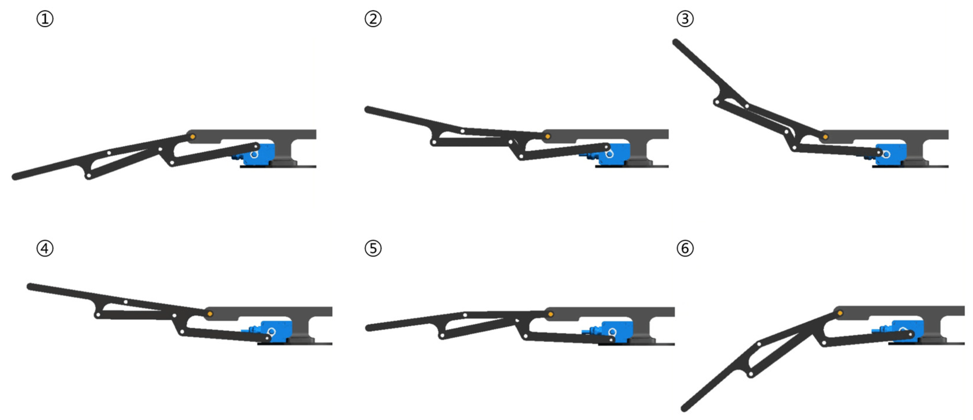
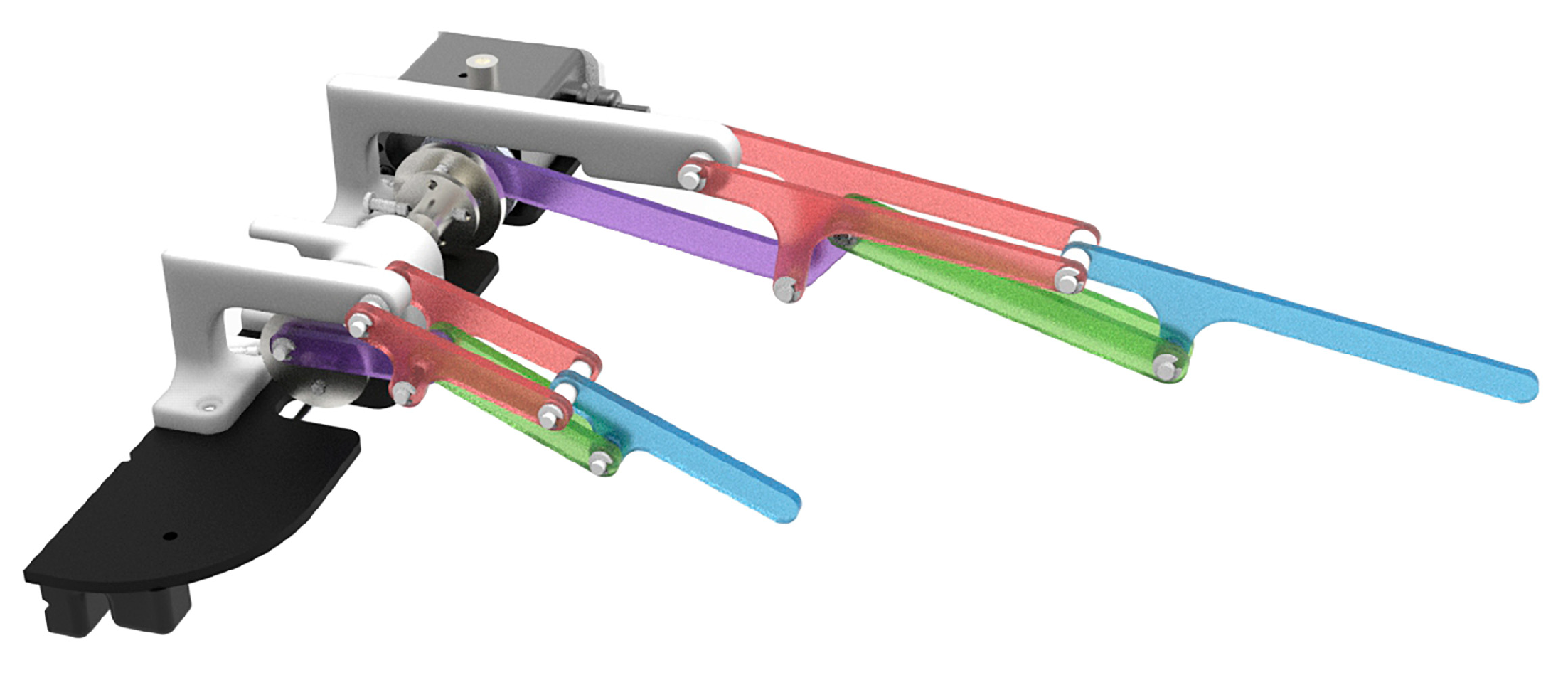
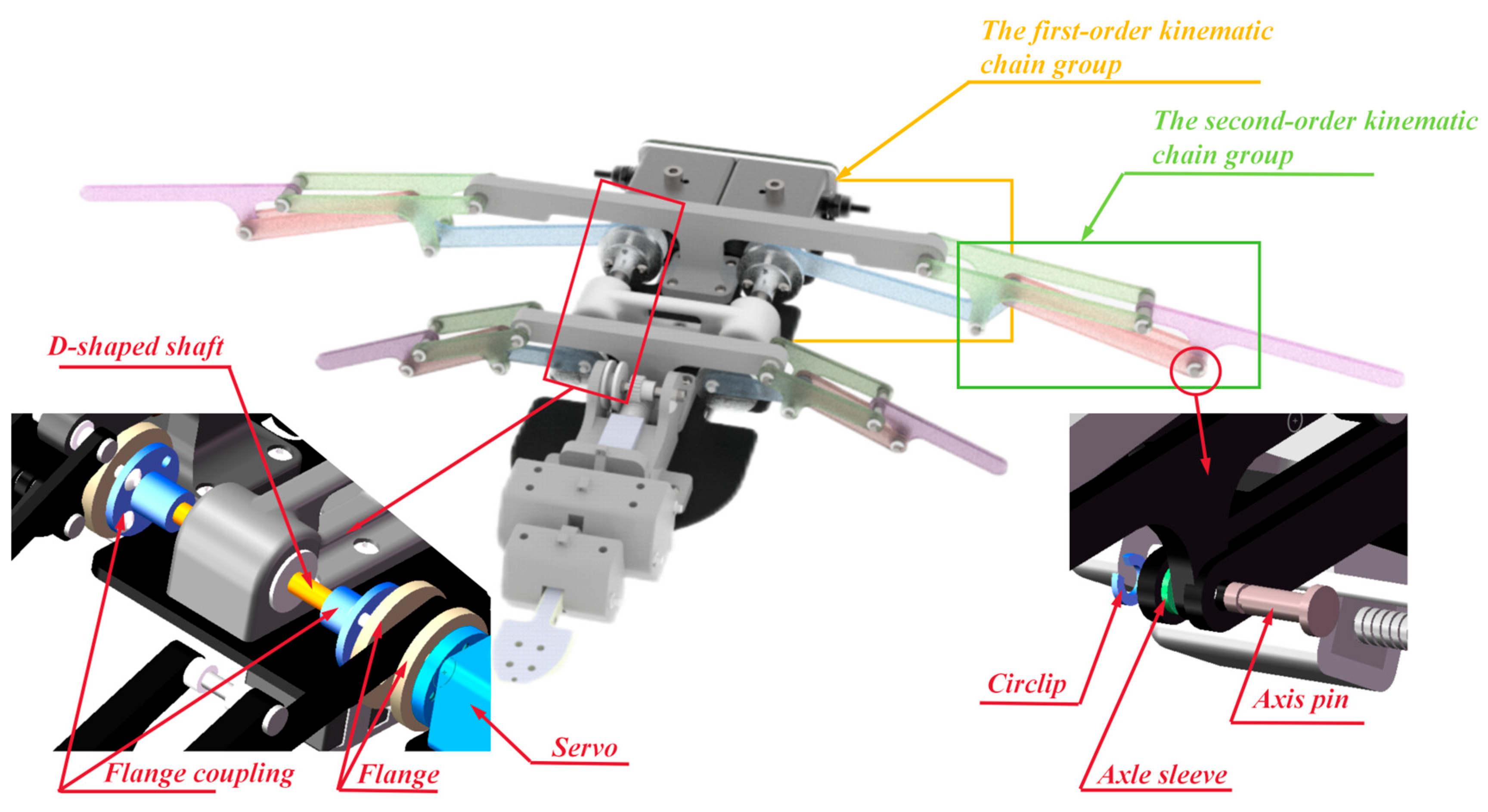
2.1. Bionic Pectoral Fin Mechanism

The section of the pectoral fin mechanism is vital in the construction of the bionic cownose ray. In selecting the bionic linkage mechanism, two fundamental criteria must be met: first, it must possess a single degree of freedom to guarantee stable and controllable motion; second, it must create a closed chain which meets the criteria for planar mechanisms with multiple closed chains and a single degree of freedom for the pectoral fins. The Kutzbac criterion [29] stipulates that the quantity of rods and the number of moving pairs in a mechanism should satisfy a specific relationship, with the number of rods needing to be even, and both the number of moving pairs and the number of moving rings must be integers. To simulate the bending state of the pectoral fins of actual cownose rays during locomotion, the bionic pectoral fin mechanism must incorporate a minimum of two tiers of motion mechanisms; thus, a six-rod mechanism is utilized. The initial tier of the fin tail in the six-rod mechanism comprises a minimum of four secondary rods. According to the Accyp principle [30], there are specific restrictions on the distribution of revolute pairs on the rod. For these four secondary rods, they are arranged in two ways, 220 and 211, on the three edges. The 220 configuration means that the numbers of secondary rods on the three edges are 2, 2, and 0, respectively, while the 211 configuration means that the numbers of secondary rods on the three edges are 2, 1, and 1. The two configurations correspond to the Watt type [31] and the Stephenson type [32]. In comparison to the Stephenson rod set, the Watt rod set exhibits superior structural characteristics for facilitating pectoral fin locomotion while adhering to fundamental design criteria. Additionally, the Watt rod set outperforms the Stephenson rod set in transmission smoothness, power transfer efficiency, and adaptability to the intricate locomotion patterns of bionic cownose rays, making it more suitable for bionic cownose rays’ locomotion requirements. After the improvement of the component length, the bionic pectoral fin of the Watt-type six-rod configuration comprises five movable elements, with a degree of freedom of 1, and the motion is determined. This arrangement satisfactorily fulfills the design specifications, as shown in Figure 2a for the mechanism sketch and Figure 2b for the 3D model rendering.
To facilitate the pectoral fin mechanism of the bionic cownose ray in generating adequate thrust during locomotion, equal proportions of bionic mechanisms are superimposed along the axial direction of the cownose ray, building upon a singular bionic pectoral fin mechanism. Based on the cownose ray’s movement attitude, the period of the pectoral fin portion’s waving movement near the head is equivalent to that of the pectoral fin portion near the tail during forward swimming. However, the waving movement of the pectoral fin portion near the head is slightly earlier than the waving movement of the pectoral fin portion near the tail. Consequently, as seen in Figure 3, two bionic mechanisms derived from a Watt-type six-bar mechanism, featuring synchronized motion and reduced size dimensions, are aligned along the axial direction of the cownose ray within the bionic cownose ray mechanism. A phase difference is established for the active parts of these two bionic mechanisms to achieve the design of the bionic mechanism.

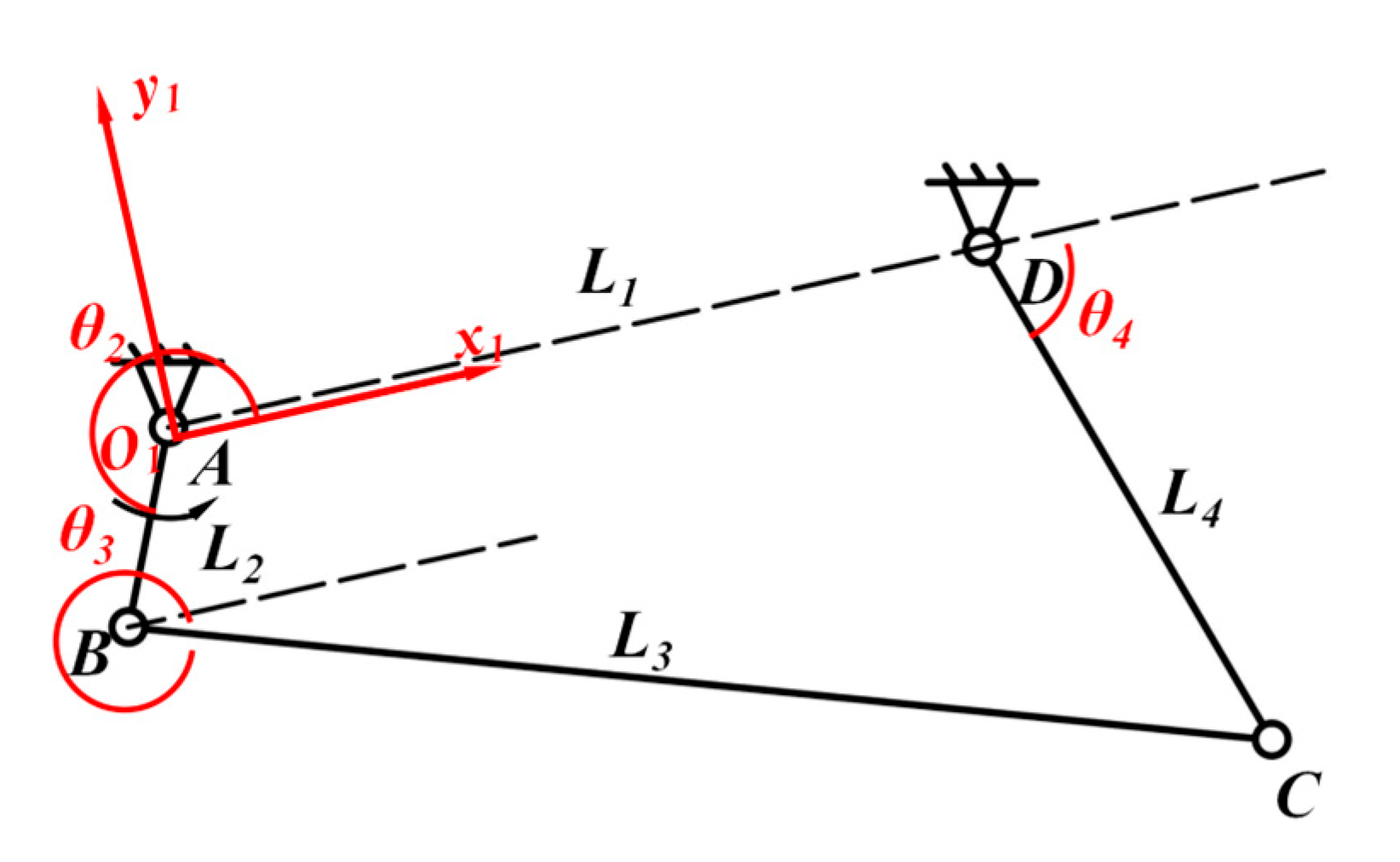
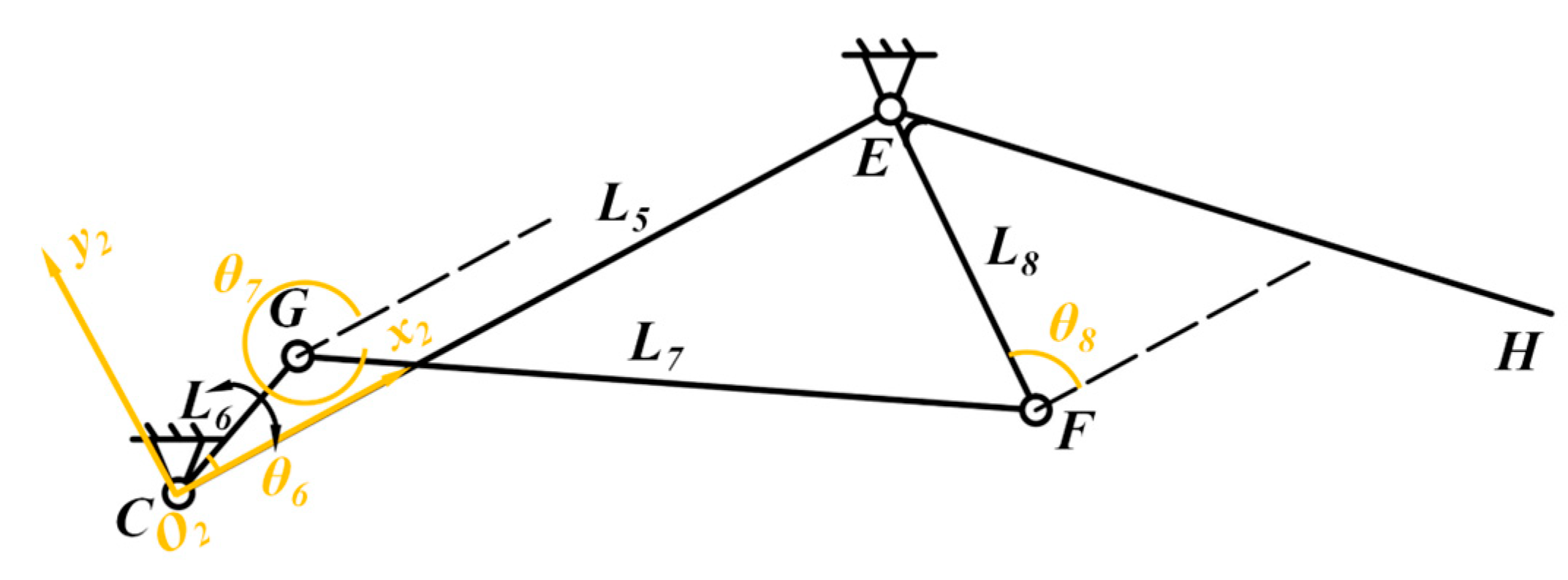
2.2. Bionic Pectoral Fin Mechanism Calculations

As shown in Figure 4, the first level of the bionic pectoral fin six-rod mechanism can be simplified to consist of components ABCD, with the AD rod serving as the fixed frame attached to the body of the bionic cownose ray and AB functioning as the active part. The entire bionic pectoral fin mechanism is actuated by the active crank AB rod, which rotates at a constant velocity for a full circle, while CDE represents the crank-rocker mechanism with the working rod. The coordinate system x1O1y1 is defined using point A as the origin and AD as the positive x-axis direction. L1, L2, L3, and L4 correspond to the four rods AD, AB, BC, and CD, respectively. l1, l2, l3, and l4 represent the lengths of the four bars L1, L2, L3, and L4, respectively. θ1, θ2, θ3, and θ4 denote the angles between L1, L2, L3, and L4 and the positive x-axis of the coordinate system x1O1y1, respectively. ω1, ω2, ω3, and ω4 denote the angular velocities of the movements of L1, L2, L3, and L4, respectively. α1, α2, α3, α4 denote the angular velocities of L1, L2, L3, and L4, respectively. The closed vector equations are derived using the vector method:
L 2 + L 3 = L 1 + L 4
It is expressed in plural form as:
l 2 e i θ 2 + l 3 e i θ 3 = l 1 e i θ 1 + l 4 e i θ 4
In the coordinate system x1O1y1, L1 coincides with the positive direction of the x-axis, so θ1 = 0. Applying Euler’s formula e = cos θ + isin θ yields a system of nonlinear equations:
f 1 ( θ 3 , θ 4 ) = l 2 cos θ 2 + l 3 cos θ 3 l 1 l 4 cos θ 4 = 0 f 1 ( θ 3 , θ 4 ) = l 2 sin θ 2 + l 3 sin θ 3 l 4 sin θ 4 = 0
The angular velocity and angular acceleration of the BC and CD rods can be solved by transforming the equations and performing derivatives:
l 2 ω 2 sin θ 2 l 3 ω 3 sin θ 3 = l 4 ω 4 sin θ 4 l 2 ω 2 cos θ 2 + l 3 ω 3 cos θ 3 = l 4 ω 4 cos θ 4
ω 3 = ω 2 l 2 sin θ 2 θ 4 l 3 sin θ 4 θ 3
ω 4 = ω 2 l 2 sin θ 2 θ 3 l 4 sin θ 4 θ 3
l 4 α 4 sin θ 4 l 3 α 3 sin θ 3 = l 2 ω 2 2 cos θ 2 + l 3 ω 3 2 cos θ 3 r 4 ω 4 2 cos θ 4 l 4 α 4 cos θ 4 l 3 α 3 cos θ 3 = l 2 ω 2 2 sin θ 2 + l 3 ω 3 2 sin θ 3 r 4 ω 4 2 sin θ 4
α 3 = ω 2 2 l 2 cos ( θ 2 θ 4 ) ω 3 2 l 3 cos ( θ 3 θ 4 ) + ω 4 2 l 4 l 3 sin ( θ 4 θ 3 )
α 4 = ω 2 2 l 2 cos ( θ 2 θ 3 ) ω 4 2 l 4 cos ( θ 4 θ 3 ) + ω 3 2 l 3 l 4 sin ( θ 4 θ 3 )
Due to the rigid fixation of rod CD and rod DE (Figure 2a), the angular velocity and angular acceleration of the motion of rod DE, the first-level actuating component of the pectoral fin mechanism of the bionic cownose ray, are ω4, α4, respectively.
The movement of the second-level mechanism of the bionic pectoral fin is driven by the CDE rod in conjunction with the BCG rod (as can be seen in Figure 2a). To enable the computation of the angular velocity and angular acceleration of the working rods, the initial coordinate system, x1O1y1, is transformed into the new coordinate system, x2O2y2, through translation and rotation. As seen in Figure 5, the simplified second-level kinematic mechanism of the bionic pectoral fin designates CE as a fixed rack and establishes the transformed coordinate system x2O2y2 with C as the origin and CE as the positive x-axis direction. Since the rods CE and CD are rigidly fixed, the transformation parameters for the coordinate system can be derived. The panning coordinate is:
l 1 + l 4 cos ω 4 t , l 4 sin ω 4 t
Rotation angle:
φ = π ω 4 t D C E
The rotation matrix R, the translation matrix T, and the transformation matrix M can be obtained from the translation coordinates and the rotation angle, respectively:
R = cos φ sin φ 0 sin φ cos φ 0 0 0 1
T = 1 0 l 1 + l 4 cos ω 4 t 0 1 l 4 sin ω 4 t 0 0 1
M = R T = cos φ sin φ l 1 + l 4 cos ω 4 t sin φ cos φ l 4 sin ω 4 t 0 0 1
Following the transformation of the coordinate system, the secondary mechanism of the pectoral fin of the bionic cownose ray may be distilled into a double-rocker mechanism, with CE serving as the fixed frame and CG as the active lever. L5, L6, L7, and L8 correspond to the four EC, CG, GF, and FE rods, respectively. θ5, θ6, θ7, and θ8 denote the angles formed by the positive x-axis with lines L5, L6, L7, and L8 relative to the coordinate system x2O2y2. ω6′, ω7′, and ω8′ denote the angular velocities of L6, L7, and L8, respectively, along the positive x-axis direction inside the coordinate system x2O2y2. ω7′ and ω8′ denote the angular velocities of L6, L7, and L8. ω7 and ω8 denote the angular velocities of the motions of L6, L7, and L8 inside the coordinate system x1O1y1, respectively. α8 denotes the angular acceleration of L8 within the x1O1y1 coordinate system. Since the bar CG is rigidly fixed to the BC bar, the velocity of motion of the bar CG within the coordinate system x2O2y2 is:
ω 6 = ω 3 + R
The angular velocities of rod EF and rod GF in the coordinate system x2O2y2 can be calculated by the same process of calculating the closed vector equations based on the vector method:
ω 8 = ω 6 l 6 sin θ 6 θ 7 l 8 sin θ 8 θ 7
ω 7 = ω 6 l 6 sin θ 6 θ 7 l 7 sin θ 8 θ 7
Combined with the angular velocity under the coordinate system x2O2y2, the angular velocity and angular acceleration of the rod EF can be solved by transforming the coordinate system. Due to the rigid fixation of rod EH and rod EF, the angular velocity and angular acceleration of the motion of rod EF, the second-level actuating component of the pectoral fin mechanism of the bionic cownose ray, are ω8, α8, respectively.
ω 8 = ω 3 + R l 6 sin θ 6 θ 7 l 8 sin θ 8 θ 7 R
ω 7 = ω 3 + R l 7 sin θ 6 θ 7 l 8 sin θ 8 θ 7 R
α 8 = ω 3 + R 2 l 6 cos ( θ 6 θ 7 ) ω 8 2 l 4 cos ( θ 8 θ 7 ) + ω 7 2 l 7 l 8 sin ( θ 8 θ 7 )

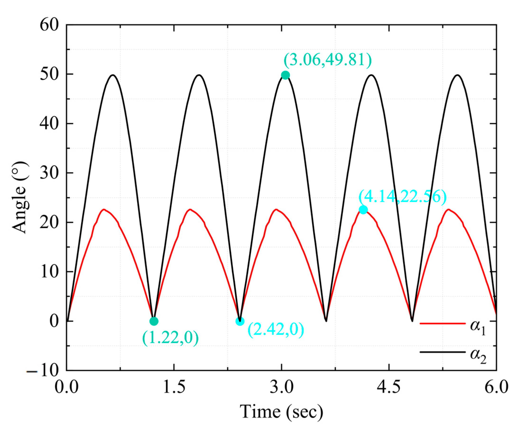
2.3. Bionic Pectoral Fin Mechanism Simulation

Based on the design outcomes, SolidWorks 2021 software is employed to create the 3D parametric model of the complete mechanism of the bionic cownose ray. SolidWorks software, which supports accurate geometric modeling and assembly analysis, is a mainstream 3D modeling tool in the field of mechanical design. To validate the kinematic feasibility of the theoretical model, the dynamic simulation software ADAMS 2020 is employed for kinematic simulation analysis. ADAMS, as a multi-body dynamics simulation software, is used to simulate the kinematic characteristics of the mechanism and verify the motion feasibility of the theoretical model by setting the rotating sub constraints and driving angular velocities. Both of these are industry-standard software and are available through academic institutional licenses or commercial licenses. In the simulation setup, the ambient gravity parameter is established at zero, the bionic cownose robot frame is rigidly fixed to the inertial reference system via fixed vice constraints, and rotating vice constraints are imposed among the components of the six-bar kinematic mechanism. The angular velocity of the servo drive for the active crank is established at 300 degrees per second to finalize the kinematic simulation. In Figure 2a, α1 and α2 are designated as the angular variables of rods DE and EH, respectively, to the global coordinate system x1 during the motion process. The simulation results, as shown in Figure 6, indicate that α1 and α2 oscillate sinusoidally in conjunction with the cyclic motion of the bionic pectoral fin, with α1 fluctuating between 0° and 22.56° and α2 varying between 0° and 49.81°.

3. Prototyping and Experimentation

3.1. Prototype Design

The experimental prototype of the bionic cownose ray was designed based on the theoretical schematic of its pectoral fin mechanism. The experimental prototype of the bionic cownose ray was created by 3D modeling and SolidWorks software. In the FDM 3D printing process, the anisotropic nature of the printing pattern results in considerable variations in the bending resistance of the completed components depending on their orientation. To safeguard the bionic mechanism of the experimental prototype of the bionic manta ray during in-water testing, the rod assembly of the pectoral fin mechanism was produced using subtractive machining. A 300 mm by 400 mm polycarbonate sheet was used as a raw material, and a micro milling machine was employed to fabricate the components. Figure 7 shows that the rods in the bionic pectoral fin mechanism are linked by axis pins, and 3D-printed axle sleeves are employed to regulate the axial positioning of the rods, thereby preventing interference during movement. The pectoral fin mechanisms on both the left and right sides of the bionic cownose ray are operated by two distinct waterproof servos. In the experiment, an external direct-current regulated power supply is adopted to supply power to two waterproof servos through waterproof cables, and the power supply is connected to the servo system via waterproof interfaces to ensure water tightness. The semi-autonomous operation of pectoral fin flapping, either synchronized or reversed, is accomplished by regulating the servo’s forward and backward rotation and speed via pre-programmed commands. Synchronized flapping of the pectoral fins generates forward force and upward lift, while steering is accomplished through the movement of a single servo or the differential action of two servos. The watertight servo is linked to a flange coupling with an inner diameter of 6 mm via the servo flange, and torque is conveyed through an eyelet connection on the flange. The two axially superimposed mechanisms are synchronized in rotation by a D-shaped shaft with a diameter of 6 mm. The torque is conveyed between the flange coupling and the D-shaped shaft through synchronized rotation secured by a top wire on the coupling. The distance from the center of the eyelet on the flange coupling to the center of the flange serves as the crank length for driving the motion of the two bionic mechanisms. The two superimposed mechanisms regulate their movement sequence through changes in the hole positions of the connecting flanges.

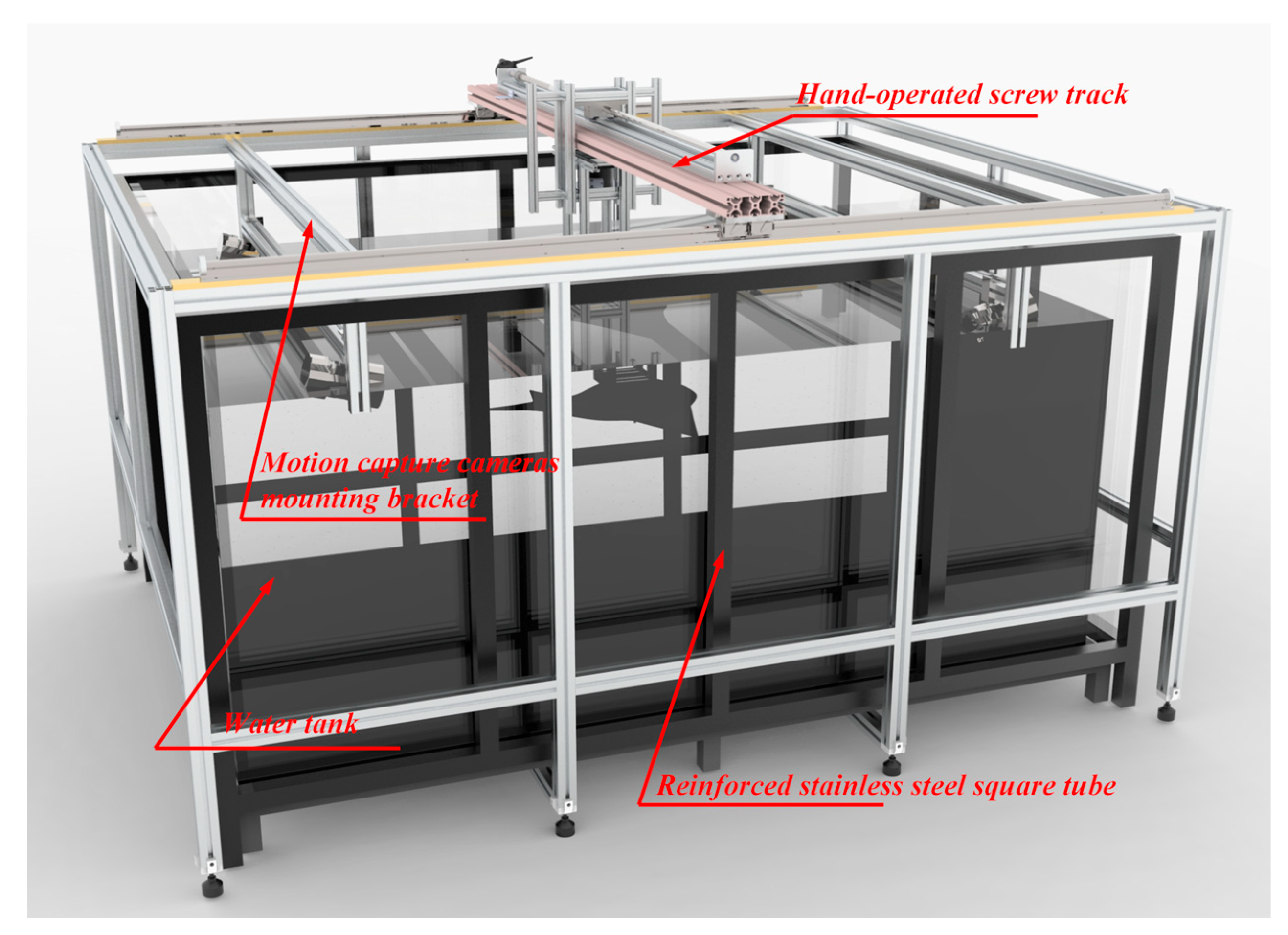
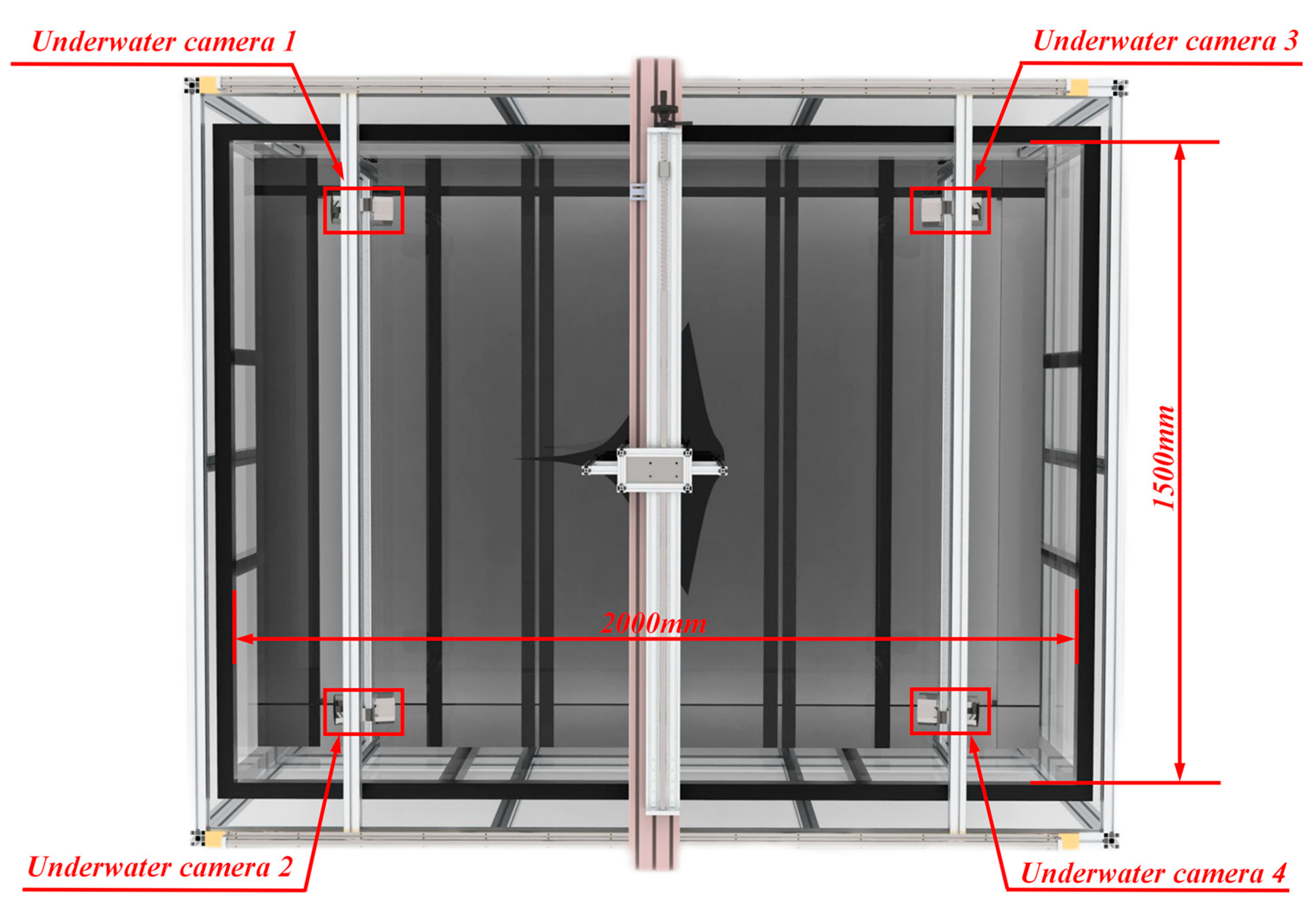
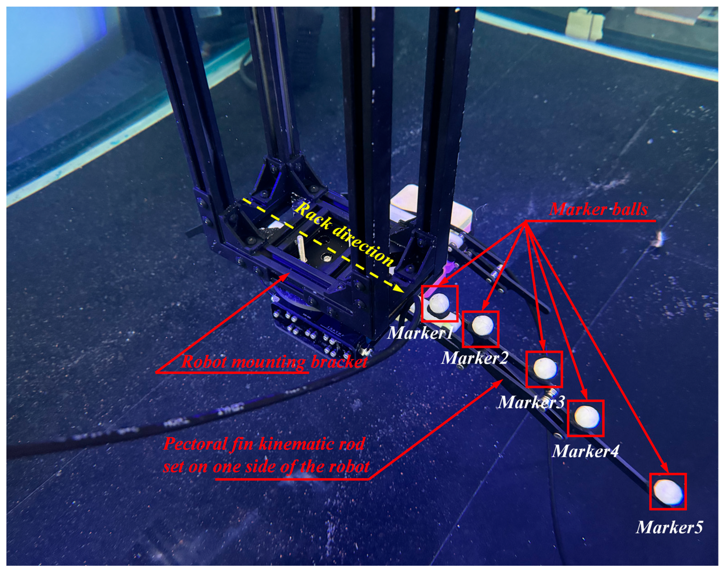
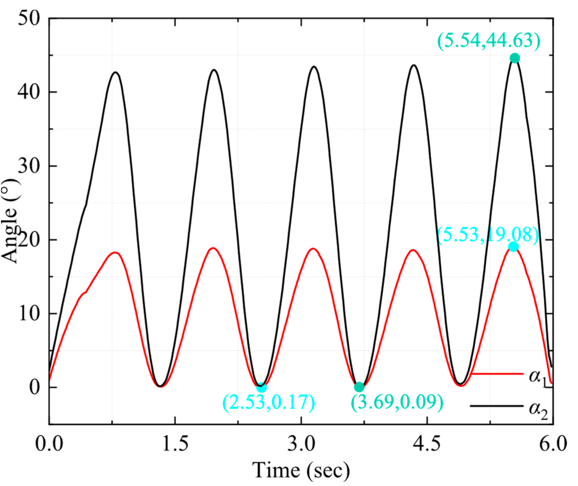
3.2. Underwater Motion Capture Experiment

To test the motion effect of the experimental prototype of the bionic cownose ray, a motion capture experiment was designed to verify the motion parameters of the experimental prototype of the bionic cownose ray. As shown in Figure 8, the experimental platform used a transparent glass pool with a length of 2000 mm, a width of 1500 mm, and a height of 1000 mm. The pool was reinforced with black lacquered stainless steel square tubes around and at the bottom. The periphery of the pool was made of 40 mm × 40 mm European standard aluminum profiles to set up a track parallel to the long side of the experimental pool, and a movable crossbeam made of 40 mm × 80 mm European standard aluminum profiles was used on the track to connect the vertical aluminum profile bracket for fixing the experimental prototype to the hand-cranked screw on the crossbeam, which was used to adjust the position of the experimental prototype in the experimental pool.
The NOKOV Motion Capture System was employed in the motion capture experiment to record and analyze the movements of the experimental prototype of the bionic cow nose ray’s motion mechanism. This experiment employed a passive marker-point optical motion capture system, with four NOKOV Motion Capture Cameras positioned at each corner of the pool to ensure the maximized capture range, as shown in Figure 9. In the motion capture experiments, to eliminate deviations in the skeletal motion data of the experimental prototype of the bionic cownose ray caused by the differing refractive indices of air and water, NOKOV’s underwater motion capture camera was employed, with the lens fully submerged to avert errors arising from the transition between media.
As shown in Figure 10, the skeletal motion of the bionic cownose ray experimental prototype was detected and spatially localized by attaching several bright reflective spheres to its skeleton, which was not covered by the bionic cownose ray’s skin. The reflective spheres reflected the LED irradiation light from the motion-capture lens back to the motion-capture camera. Given the prototype’s symmetry, it was sufficient to capture only one side. In the experiment, the prototype’s frame was fixed to the end of an adjustable vertical bracket, which could be locked in position to eliminate data variation caused by the prototype’s movement. The experimental prototype was fixed in the middle of the tank by means of a hand-crank screw so that its center axis was exactly 1000 mm and 750 mm away from the wide and long sides of the tank to determine the specific positioning of the robot. The length of the fixed bracket and the distance between each marker and the center of the frame at initial standstill can be used to determine the specific initial position of the markers in three-dimensional space. At the beginning of the experiment, the drive servo of the bionic mechanism on the side of the marker was energized, and the motion data of the bionic mechanism was acquired by NOKOV’s underwater motion-capture camera and communicated to the computer. Five sets of motion-capture data were obtained by repeatedly performing the motion of the bionic mechanism to reduce random and systematic faults. The angle between the line connecting Marker 2 and Marker 3 and the direction of the rack depicted in Figure 10 are designated as α1, while the angle between the line connecting Marker 4 and Marker 5 and the direction of the rack in Figure 10 are designated as α2. The variation curves of α1 and α2 during the robot’s motion are illustrated in Figure 11. The research reveals that the angle α1 of the first-level actuator varies between 0° and 20° during motion, while the angle α2 changes between 0° and 45°, with α1 reaching a maximum of 19.08° and α2 a maximum of 44.63°. In comparison to the ADAMS simulation results shown in Section 2.3, the two angles obtained from the underwater motion capture tests are smaller. This discrepancy arises because the ADAMS simulation operates under vacuum conditions, devoid of motion resistance effects. The turbulence and eddies of the water current, along with the interference from the surrounding flow during actual underwater experiments, create additional fluid resistance and unstable forces on the robot, impeding the movement of the rods and consequently diminishing the motion angles.

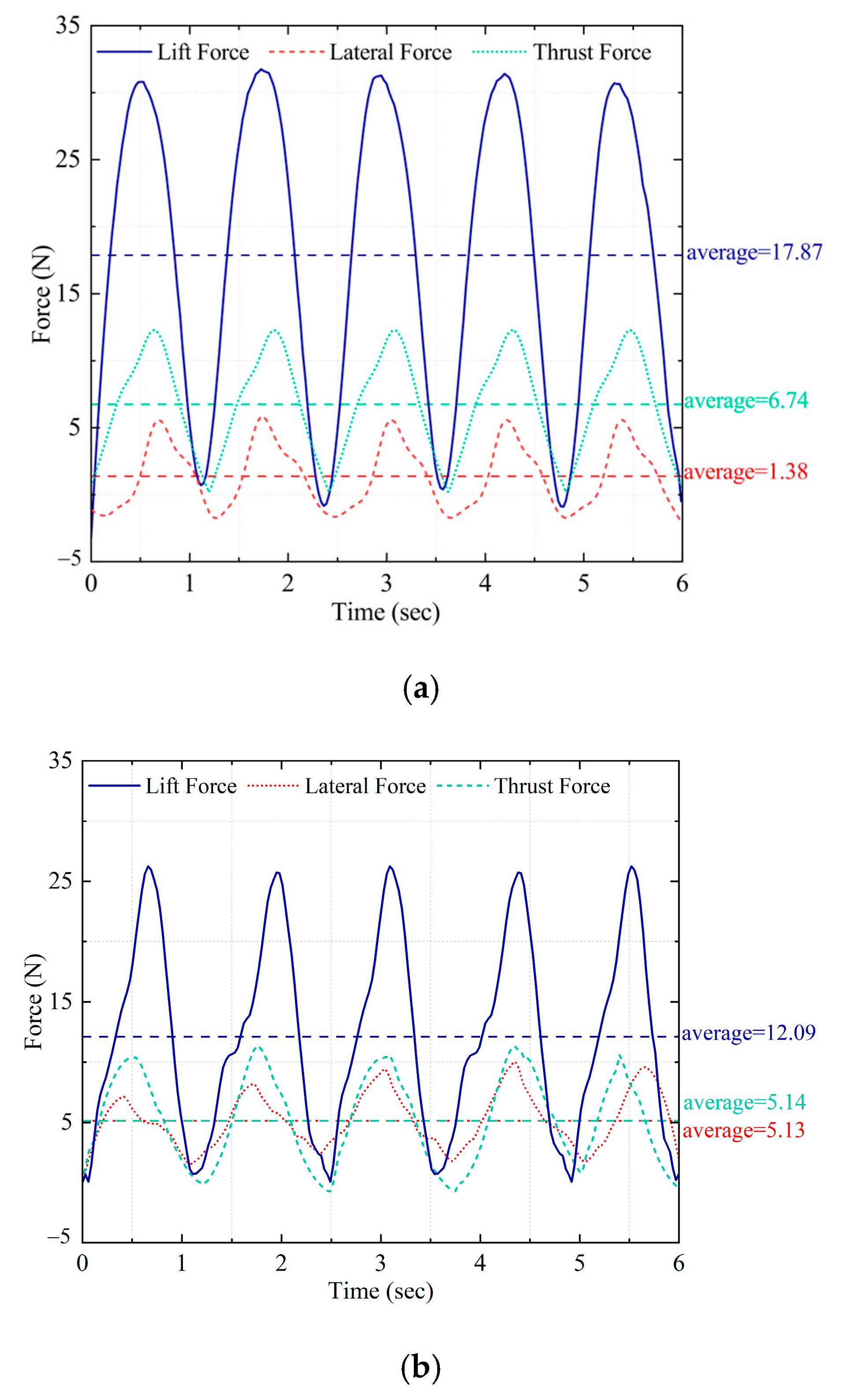
3.3. Underwater Six-Dimensional Force Experiment

The motion-capture markings on the experimental prototype of the bionic cownose ray were removed following the completion of the experiment. To further examine the propulsive efficacy of the bionic cownose ray robot during underwater locomotion, a six-dimensional force sensor was employed in the same experimental pool. Figure 12 shows that a 0.5 mm black silicone layer was used to laminate the bionic skin of the experimental prototype of the bionic cownose ray, enabling it to generate a greater reaction force during underwater locomotion. The coated bionic cownose ray was fixed to the end of a vertical aluminum profile holder equipped with a six-dimensional force sensor. Initially, the drive motors of the bionic mechanism on either side were activated. By modulating the motors’ rotational speed, the pectoral fins of the bionic manta ray robot were synchronized and inverted, while data from their movements were recorded and transmitted to the computer. Numerous collections of six-dimensional force data were acquired by repeatedly executing the bionic mechanism motions to reduce random and systematic errors. The collected data were averaged and analyzed, revealing that all three forces exhibited periodic variations, as shown in Figure 13. Figure 13a shows the thrust, lift, and lateral force profiles during the synchronized flapping of the pectoral fins on each side of the bionic cownose ray robot. The analysis indicates that the synchronized flapping of the robot’s pectoral fins produces a positive thrust force, averaging approximately 6.74 N. The vertical lift force is comparatively greater, averaging 17.87 N, thus enhancing the robot’s swimming capability in the vertical direction. The mean lateral force is around 1.38 N, and the yaw force is minimal, suggesting that the robot can achieve smooth forward motion during the synchronized flapping of the pectoral fins on either side. Figure 13b shows the thrust, lift, and lateral force profiles of the bionic cownose ray robot during the reverse-phase flapping of the pectoral fins on both sides. The comparison indicates that the robot can produce positive propulsion during the asynchronous flapping of both pectoral fins; however, the thrust force is lower than that of synchronous flapping, averaging approximately 5.14 N. The vertical lift force is comparatively reduced, averaging approximately 12.09 N. The average lateral force is comparatively greater, at approximately 5.13 N, allowing the robot to execute a turning motion due to the lateral force generated during the inverse movement of the pectoral fins on both sides. The robot can execute a turning motion by the lateral force generated during the retraction of the two pectoral fins.

4. Conclusions

This paper proposes a biomimetic design strategy to replicate the pectoral fin movement of a cownose ray using four six-bar systems. The design criteria for stable and controllable movement of the biomimetic mechanism, along with the establishment of a closed chain, were fulfilled by selecting the Watt-type six-bar mechanism. Additionally, the axial superposition of the mechanism and the adjustment of the phase difference effectively simulate the pectoral fin waving of the cownose ray. Underwater passive marking point optical motion-capture experiments revealed that the motion range of the first stage of the six-rod mechanism at the anterior section of the bionic manta ray’s pectoral fin is 0–19.08°, while the motion range of the second stage is 0–44.63°, which were smaller than those of the ADAMS mechanism simulation results. This discrepancy stems from fluid drag, turbulence, and mechanical friction in the actual water flow, verifying that the simulation environment does not fully model the effects of dynamic drag. The angular range of motion is diminished compared to the ADAMS mechanism simulation findings because of resistance and current interference in the water; nonetheless, the trend of both variations remains consistent, demonstrating the kinematic viability of the theoretical model. The six-dimensional force experiments indicate that when the bionic cownose ray’s pectoral fins flap synchronously, they produce an average forward thrust of approximately 6.74 N and a lift of up to 17.87 N, while the lateral force is merely about 1.38 N, realizing smooth forward motion. Conversely, when flapping in opposite phases, both thrust and lift are reduced. However, the average lateral force of approximately 5.13 N allows for effective turning maneuvers, which demonstrates good propulsive performance and motion control capabilities. This study presents an innovative concept for underwater robot design, with the proposed bionic design scheme demonstrating significant advantages in locomotion performance. It offers exceptional thrust and lift capabilities for the bionic cownose ray, characterized by a compact fuselage and wingspan, thereby augmenting the robot’s flexibility. In future work, the research will focus on introducing computational fluid dynamics (CFD) modeling in simulation tests to change the kinematic model to improve the model’s adaptability to the real environment. Based on this, adaptive control algorithms will be developed to compensate for motion degradation caused by drag. Adopting high-performance flexible bionic materials can reduce water disturbance and improve energy transfer efficiency to further enhance the robot’s stability and operational capability in complex flow fields.

Author Contributions

Conceptualization, Y.C. and X.W.; methodology, Y.C.; software, X.W.; validation, Y.C. and T.H.; formal analysis, Y.D.; investigation, T.H.; resources, T.Y.; data curation, Y.C.; writing—original draft preparation, Y.C. and X.W.; writing—review and editing, Y.C.; visualization, Y.F.; supervision, Y.C.; project administration, Y.C.; funding acquisition, T.Y. All authors have read and agreed to the published version of the manuscript.

Funding

This research was funded by the National Natural Science Foundation of China (U23B20106).

Data Availability Statement

The data presented in this study are available on request from the corresponding author.

Conflicts of Interest

Author Yichen Chu was employed by the Beijing Lindong Bionic Science and Technology Limited Company. The remaining authors declare that the research was conducted in the absence of any commercial or financial relationships that could be construed as a potential conflict of interest.

References

  1. Li, S.; Wu, Z.; Wang, J.; Feng, Y.; Tan, M.; Yu, J. Towards Efficient Intermittent-Propulsion Mode of a Novel Bioinspired Underwater Vehicle. IEEE Trans. Intell. Veh. 2024, 1–13. [Google Scholar] [CrossRef]
  2. Liu, T.; Liu, Y.; Zeng, R.; Gan, B.; Zhang, M.; Li, H.; Qu, S.; Zhou, H. A Bioinspired Multimotion Modality Underwater Microrobot. Sci. Adv. 2025, 11, eadu2527. [Google Scholar] [CrossRef] [PubMed]
  3. Ma, S.; Guo, W.; Song, R.; Liu, Y. Unsupervised Learning Based Coordinated Multi-Task Allocation for Unmanned Surface Vehicles. Neurocomputing 2021, 420, 227–245. [Google Scholar] [CrossRef]
  4. Prakash, A.; Nair, A.R.; Arunav, H.; Rthuraj, P.R.; Akhil, V.M.; Tawk, C.; Shankar, K.V. Bioinspiration and Biomimetics in Marine Robotics: A Review on Current Applications and Future Trends. Bioinspiration Biomim. 2024, 19, 031002. [Google Scholar] [CrossRef]
  5. Hussein, A.A.; Ragab, S.A.; Hajj, M.R.; Patil, M.J. Material and Geometric Effects on Propulsion of a Fish Tail. Bioinspiration Biomim. 2021, 16, 066008. [Google Scholar] [CrossRef] [PubMed]
  6. Luo, Y.; Xiao, Q.; Zhu, Q.; Pan, G. Jet Propulsion of a Squid-Inspired Swimmer in the Presence of Background Flow. Phys. Fluids 2021, 33, 031909. [Google Scholar] [CrossRef]
  7. Cui, Z.; Li, L.; Wang, Y.; Zhong, Z.; Li, J. Review of Research and Control Technology of Underwater Bionic Robots. Intell. Mar. Technol. Syst. 2023, 1, 7. [Google Scholar] [CrossRef]
  8. Wang, W.; Li, W.; Xu, J.; Dong, J.; Xiang, C.; Guan, Y.; Zhang, T. Design and Implementation of a Miniature Jellyfish-Inspired Robot. IEEE Robot. Autom. Lett. 2023, 8, 3134–3141. [Google Scholar] [CrossRef]
  9. Godaba, H.; Li, J.; Wang, Y.; Zhu, J. A Soft Jellyfish Robot Driven by a Dielectric Elastomer Actuator. IEEE Robot. Autom. Lett. 2016, 1, 624–631. [Google Scholar] [CrossRef]
  10. Liu, J.; Hu, H. Biological Inspiration: From Carangiform Fish to Multi-Joint Robotic Fish. J. Bionic Eng. 2010, 7, 35–48. [Google Scholar] [CrossRef]
  11. Yan, S.; Wu, Z.; Wang, J.; Huang, Y.; Tan, M.; Yu, J. Real-World Learning Control for Autonomous Exploration of a Biomimetic Robotic Shark. IEEE Trans. Ind. Electron. 2023, 70, 3966–3974. [Google Scholar] [CrossRef]
  12. Wang, R.; Wang, S.; Wang, Y.; Cheng, L.; Tan, M. Development and Motion Control of Biomimetic Underwater Robots: A Survey. IEEE Trans. Syst. Man. Cybern. Syst. 2022, 52, 833–844. [Google Scholar] [CrossRef]
  13. Zeng, X.; Xia, M.; Luo, Z.; Shang, J.; Xu, Y.; Yin, Q. Design and Control of an Underwater Robot Based on Hybrid Propulsion of Quadrotor and Bionic Undulating Fin. J. Mar. Sci. Eng. 2022, 10, 1327. [Google Scholar] [CrossRef]
  14. Shen, Y.; Ding, Z.; Wang, X.; Mao, Z.; Huang, Z.; Chen, B. Biomimetic Hydrofoil Propulsion: Harnessing the Propulsive Capabilities of Sea Turtles and Penguins for Robotics. Biomimetics 2025, 10, 272. [Google Scholar] [CrossRef]
  15. Song, Z.; Zhu, J.; Wang, C. Optimization of Semi-Active Hydrofoil Propulsion Performance Based on CFD Taguchi Method and Neural Network. Eur. J. Mech. B Fluids 2024, 105, 327–337. [Google Scholar] [CrossRef]
  16. Wang, Z.; Zheng, A.; Guo, S. Dynamics Evaluation of a Magnetic Actuated Soft Bionic Minirobot with Paired Fin. In Proceedings of the 2024 IEEE International Conference on Mechatronics and Automation (ICMA), Tianjin, China, 4–7 August 2024; pp. 674–678. [Google Scholar]
  17. Su, Z.; Yu, F.; Zhu, B.; Han, W.; Wang, Q.; Li, W. Dynamic Analysis of the Sinusoidal Actuation of a Flexible Fin for Paired Fin Propulsion. Phys. Fluids 2022, 34, 051909. [Google Scholar] [CrossRef]
  18. Shi, X.; Chen, Z.; Zhang, T.; Li, S.; Zeng, Y.; Chen, L.; Hu, Q. Hydrodynamic Performance of a Biomimetic Undulating Fin Robot under Different Water Conditions. Ocean Eng. 2023, 288, 116068. [Google Scholar] [CrossRef]
  19. Xu, L.; Mei, T.; Huan, J.; Luo, M.; Wei, X.; Cao, K. Research on Dynamical Mechanism and Propulsion System of a Biped Robot Walking on Water. Robot 2013, 35, 257. [Google Scholar] [CrossRef]
  20. Mignano, A.P.; Kadapa, S.; Drago, A.C.; Lauder, G.V.; Kwatny, H.G.; Tangorra, J.L. Fish Robotics: Multi-Fin Propulsion and the Coupling of Fin Phase, Spacing, and Compliance. Bioinspiration Biomim. 2024, 19, 026006. [Google Scholar] [CrossRef]
  21. Luo, Y.; Hou, Z.; Chen, D.; Xu, T.; Huang, Q.; Ye, P.; Pan, G. Study on the Hydrodynamics of a Cownose Ray’s Flapping Pectoral Fin Model near the Ground. J. Mar. Sci. Eng. 2024, 12, 2024. [Google Scholar] [CrossRef]
  22. Zhang, L.; Bi, S.; Cai, Y.; Niu, C.; Ma, H. Effect Analysis of Chordwise Flexibility on Propulsion Performance of Oscillating Pectoral Foils. In Proceedings of the 2012 IEEE International Conference on Robotics and Biomimetics (ROBIO), Guangzhou, China, 11–14 December 2012; pp. 765–770. [Google Scholar]
  23. Chen, L.; Bi, S.; Cai, Y.; Cao, Y.; Pan, G. Design and Experimental Research on a Bionic Robot Fish with Tri-Dimensional Soft Pectoral Fins Inspired by Cownose Ray. J. Mar. Sci. Eng. 2022, 10, 537. [Google Scholar] [CrossRef]
  24. Cai, Y.; Bi, S.; Zheng, L. Design Optimization of a Bionic Fish with Multi-Joint Fin Rays. Adv. Robot. 2012, 26, 177–196. [Google Scholar] [CrossRef]
  25. Yu, Z.; Li, K.; Ji, Y.; Yang, S.X. Fast Motion Performance of a Bionic Ray Robot with Serial Pectoral Fins. IEEE Robot. Autom. Lett. 2023, 8, 7218–7225. [Google Scholar] [CrossRef]
  26. He, J.; Cao, Y.; Huang, Q.; Cao, Y.; Tu, C.; Pan, G. A New Type of Bionic Manta Ray Robot. In Proceedings of the Global Oceans 2020: Singapore—U.S. Gulf Coast, Online, 5–30 October 2020; pp. 1–6. [Google Scholar]
  27. Wang, R.; Zhang, C.; Zhang, Y.; Yang, L.; Qin, H.; Zhang, Q.; Yang, Y.; Liu, L. Soft Manta Ray Robot Based on Bilateral Bionic Muscle Actuator. IEEE Robot. Autom. Lett. 2024, 9, 7723–7730. [Google Scholar] [CrossRef]
  28. He, J.; Cao, Y.; Huang, Q.; Pan, G.; Dong, X.; Cao, Y. Effects of Bionic Pectoral Fin Rays’ Spanwise Flexibility on Forwarding Propulsion Performance. J. Mar. Sci. Eng. 2022, 10, 783. [Google Scholar] [CrossRef]
  29. Sameh, A.; Fanni, M.; Parque, V.; Mohamed, A.M. Development of a Balanced 3D Translational Interconnected Manipulator with Solely Rotary Joints/Actuators and Free-Internal-Singularity Workspace. IEEE Access 2021, 9, 167880–167899. [Google Scholar] [CrossRef]
  30. Sun, Q.; Wu, J.; Sheng, C.; Hu, S.; Wang, Z.; Huang, H. Design and Implementation of Multi-Level Linkage Mechanism Bionic Pectoral Fin for Manta Ray Robot. Ocean. Eng. 2023, 284, 115152. [Google Scholar] [CrossRef]
  31. Zhang, Y.; Deng, X.; Zhou, B.; Zhao, P. Design and Optimization of a Multi-Mode Single-DOF Watt-I Six-Bar Mechanism with One Adjustable Parameter. In Proceedings of the Advances in Mechanism, Machine Science and Engineering in China. CCMMS 2022, Yantai, China, 30 July–1 August 2022; Lecture Notes in Mechanical Engineering. Springer: Singapore, 2023; pp. 1373–1390. [Google Scholar] [CrossRef]
  32. Tuleshov, A.; Halicioglu, R.; Shadymanova, A.; Kuatova, M. Kinematic Synthesis Method and Eccentricity Effects of a Stephenson Mechanism. Mech. Sci. 2021, 12, 1–8. [Google Scholar] [CrossRef]
Figure 1. Motion processes in a single cycle of a bionic cownose ray robot. (① Pectoral fin initiation phase; ② Pectoral fin upward lift propulsion phase; ③ Pectoral fin movement peak; ④ Pectoral fin downward push thrust; ⑤ Pectoral fin downward push recovery preparation phase; ⑥ Pectoral fin movement trough).
Jmse 13 01156 g001
Figure 2. Pectoral fin mechanism of a bionic cownose finch ray based on Watt-type six-bar mechanism design: (a) Mechanism sketch; (b) 3D model rendering.
Jmse 13 01156 g002
Figure 3. Axially superimposed bionic cownose ray mechanism.
Jmse 13 01156 g003
Figure 4. Simplified first-level mechanism of the bionic pectoral fins.
Jmse 13 01156 g004
Figure 5. Simplified second-level mechanism of the bionic pectoral fins.
Jmse 13 01156 g005
Figure 6. Variation curves of angle α1 and α2 during robot motion in ADAMS simulation environment.
Jmse 13 01156 g006
Figure 7. Installation schematic of the bionic cownose ray robot.
Jmse 13 01156 g007
Figure 8. Schematic diagram of motion capture experiment platform.
Jmse 13 01156 g008
Figure 9. Distribution of motion capture cameras in the overhead platform view.
Jmse 13 01156 g009
Figure 10. Schematic diagram of the robot skeleton and reflective ball marking points.
Jmse 13 01156 g010
Figure 11. Angle changes of the first- and second-level actuators in underwater motion-capture experiments.
Jmse 13 01156 g011
Figure 12. Six-dimensional force experiments on a bionic cownose ray robot after lamination.
Jmse 13 01156 g012
Figure 13. Six-dimensional force data for a bionic cownose ray robot: (a) Six-dimensional force data for synchronized movement of both pectoral fins; (b) Six-dimensional force data for the reversed-phase motion of both pectoral fins.
Jmse 13 01156 g013
Disclaimer/Publisher’s Note: The statements, opinions and data contained in all publications are solely those of the individual author(s) and contributor(s) and not of MDPI and/or the editor(s). MDPI and/or the editor(s) disclaim responsibility for any injury to people or property resulting from any ideas, methods, instructions or products referred to in the content.

