1. Introduction
Over the past three decades, turbo equalizers have become extensively utilized in inter-symbol interference (ISI) channels, such as typical shallow water acoustic channels [
1,
2,
3], owing to their robust detection capabilities, which enable performance close to channel capacity. Typically, turbo equalization operating with channel coding is referred to as conventional turbo equalization (CTE). In CTE, channel coding plays a crucial role by assisting in the construction of a soft decoder behind the equalizer, thereby providing prior information for subsequent iterations.
Extensive research by scholars has delved into CTE since 1995 [
4]. The early turbo equalization employs the BCJR algorithm based on maximum a posteriori (MAP) for optimal detection performance [
5], albeit at the cost of significant computational load. Subsequently, sub-optimal algorithms like the minimum mean square error (MMSE) linear equalizer and the MMSE decision feedback equalizer (DFE) are introduced [
6]. Still, they involve matrix inversion operations for equalizer coefficient solving, leading to other, lower-complexity equalizers with slight performance trade-offs [
7], such as low-complexity fully adaptive turbo equalization [
8]. In addition to the above-mentioned CTEs based on channel estimation, adaptation-based CTE approaches exist that differ in external information computation but converge quickly after a few iterations [
9]. Benefiting from the improvement of bit error rate (BER), CTE is widely used in single carrier (SC) [
1], orthogonal frequency division multiplexing (OFDM), and orthogonal time frequency space (OTFS) [
9,
10]. Practical applications of CTE must also contend with time-varying channel characteristics, especially in complex environments like underwater acoustic channels. Consequently, methods such as basis decomposition, Bayesian learning, joint iteration, expectation propagation, factor graph, and deep learning in the turbo equalization framework have demonstrated superior performance [
11,
12,
13,
14,
15,
16]. However, CTE relies on channel coding for error control by adding redundancy, which inevitably reduces the communication rate, presenting a notable drawback.
Turbo equalization without channel coding (TECC) refers to turbo equalization that does not rely on channel coding for iteration and external information exchange. TECC can offer a notable boost in communication throughput compared with CTE. It is particularly well suited for scenarios where minor bit errors can be tolerated, such as real-time voice communication and live image transmission. However, TECC has not been studied yet, and some literature with similar concepts can still be found, which is classified in
Table 1. For instance, to effectively mitigate ISI, the chip-interleaved code-division multiple access (CDMA) system treats Pseudorandom noise (PN) sequence modulation as a form of channel coding and applies the principles of turbo equalization for iterative processing [
17]. The PN sequence modulation and channel are analogous to two turbo-code encoders. This approach has also been extended to power-interleaved CDMA systems [
18]. Some works [
19,
20] do not use turbo equalization but have also achieved performance improvements through iterative processing ideas without relying on channel coding. For example, the “operator-perturbation technique” is used to iteratively eliminate inter-subcarrier interference in OFDM systems [
19]. In SC systems, a novel decision-aided phase noise compensation scheme has been proposed, where data decisions from previous iterations are used to estimate and compensate for phase noise effects [
20]. In OTFS, the author in [
21] shows that the performance gain due to iterations comes from the non-Gaussian constellation constraint in the delay-Doppler domain. These approaches showcase the potential for achieving effective equalization and interference mitigation without explicit reliance on channel-coding paradigms.
Currently, most of the research focuses on CTE, which relies on channel coding and turbo iteration to reduce the bit error rate. This is a technology that requires channel coding. However, there is little research on TECC, which does not require channel coding. This paper aims to fill this research gap and proposes a TECC structure that implements turbo iteration through a virtual decoder.
For TECC, handling the transmission of external information poses a challenging problem. Without channel coding, the absence of a decoder means that external information transfer cannot be achieved. However, creating a suitable virtual decoder makes it possible to realize the transfer of external information. This forms the central focus of TECC research explored in this paper. Consequently, this paper introduces a TECC structure based on a virtual decoder, with the specific contributions as follows:
- (a)
A new concept of TECC based on a virtual decoder is proposed, implementing turbo iteration, without introducing rate reduction, and reducing the bit error rate.
- (b)
The corresponding way of decoding output and external information transmission in the virtual decoder is also given, which is based on bidirectional processing. A practical implementation of TECC structure with MMSE-DFE is proposed, and its convergence and superiority are verified through numerical simulations.
- (c)
We successfully applied TECC-MMSE-DFE to actual underwater acoustic communication scenarios, achieving better error performance than traditional algorithms
The rest of this paper is organized as follows.
Section 2 provides a concise overview of the principles behind CTE, followed by an explanation of the principles underlying TECC.
Section 3 introduces the specific TECC-MMSE-DFE structure and reveals its acceptable complexity. The BER performance of the proposed TECC is presented and compared in
Section 4 through numerical simulations. Experimental verification based on underwater acoustic communication is described in
Section 5.
Section 6 summarizes the conclusions drawn from our study.
2. The Structure of Proposed TECC
Consider linear modulation over a baseband, discrete-time, symbol-spaced channel corrupted by additive white Gaussian noise (AWGN). When the channel is time-invariant, the received symbol at time
n is given by
where
h = [
]
T
is the channel impulse response,
is the kth tap of
,
L is the tap length of the channel under the symbol interval,
is the
nth transmitted symbol, and
is AWGN with variance
. When the channel is time-variant, the received symbol at time
n is given by
where
is the channel impulse response at time
n, and
is the kth tap of
. It is assumed that
,
, and
are all known to the receiver. For simplicity, the entire paper is derived and analyzed using binary phase shift keying (BPSK) modulation without loss of generality. The transmitted bits are given by
, where
and
N is the number of the transmitted bits.
In this section, the principle of CTE is briefly reviewed. Then, the structure of TECC is shown, and the implementation of a virtual decoder from the perspective of bidirectional processing is displayed.
2.1. A Brief Principle Review of CTE
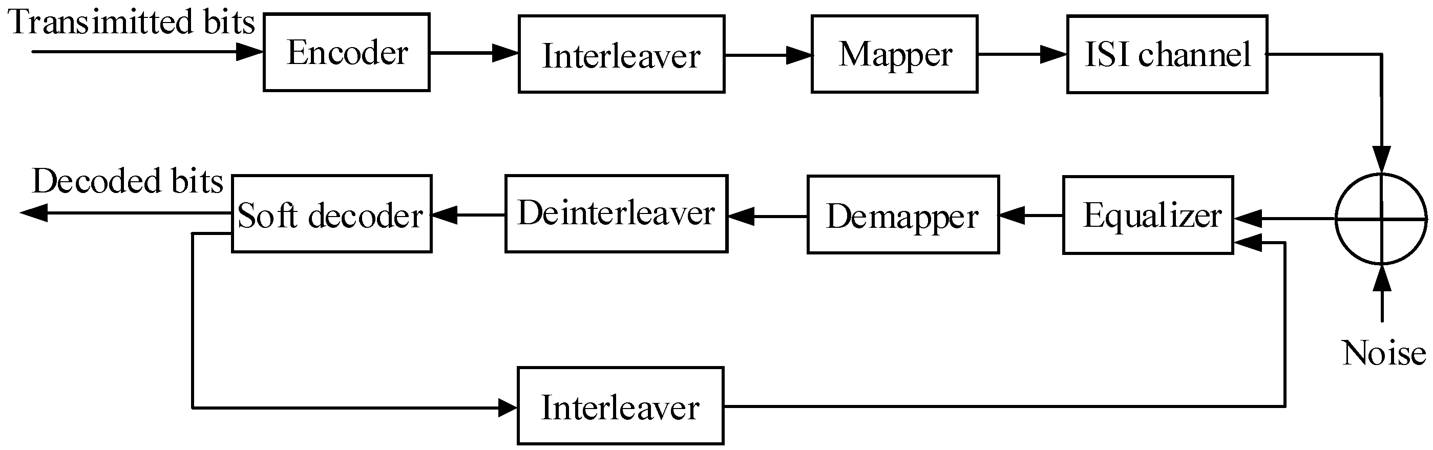
As shown in
Figure 1, the transmitter corresponding to CTE comprises an encoder, interleaver, and mapper, while the receiver includes an equalizer, demapper, deinterleaver, interleaver, and soft decoder. The external information is transferred between the equalizer and the soft decoder, thereby improving the bit error rate of the output bits.
The equalizer receives external information from the previous iteration and provides the soft decoder with external information. Conversely, the soft decoder receives the external information from the equalizer of this iteration, thereby providing more accurate external information to the equalizer of the next iteration. As the number of iterations increases, the results of the equalizer and decoder gradually improve, leading to CTE’s performance approaching the channel capacity. In CTE, the interleaver and deinterleaver play a significant role in soft information conversion by assuming that adjacent bits are uncorrelated. The interleaved sequence’s random arrangement satisfies this requirement.
However, in the absence of channel coding, the soft decoder becomes redundant. Since no soft decoder provides external information, the equalizer cannot output accurate external information in the next iteration. Therefore, the presence of channel coding is crucial in CTE.
2.2. Structure of TECC
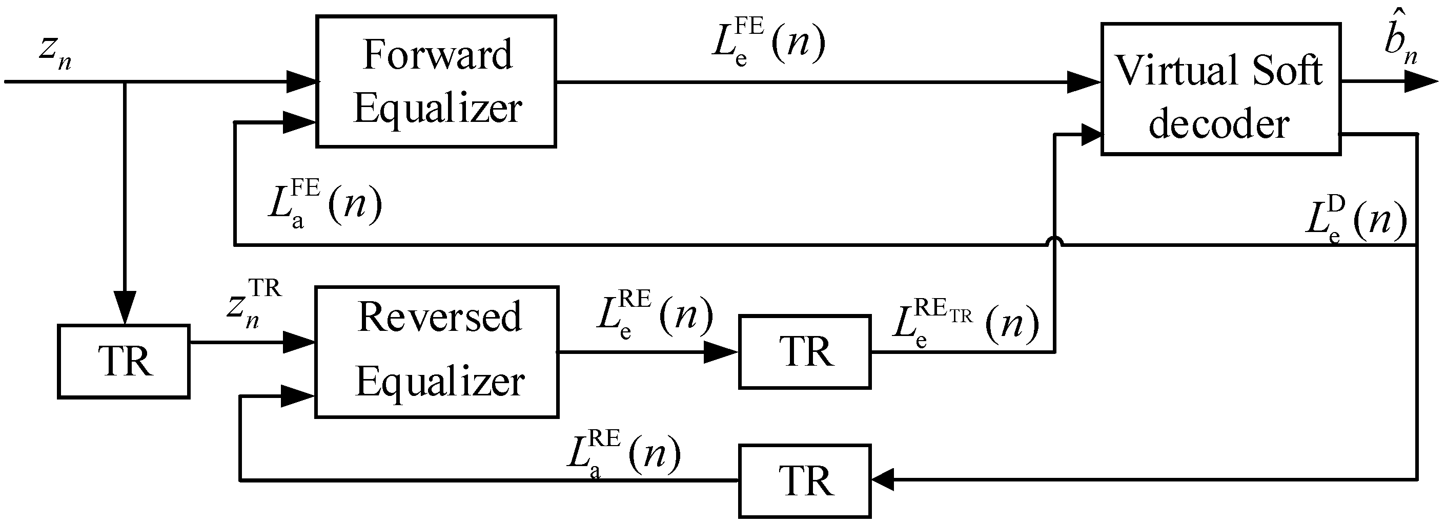
The specific TECC structure is shown in
Figure 2, where TECC consists of a forward equalizer (FE), a reverse equalizer (RE), time reversal (TR) operations, and a virtual soft decoder (VSD). VSD is a decoder that decodes symbol information into bit information and outputs external information. Since CTE needs to rely on channel coding to make the soft decoder run, this paper constructs a virtual decoder without channel coding to achieve the same function as the soft decoder in CTE. The FE and RE filter the received symbol
and
, respectively, to remove ISI, and
is given by
The input of VSD consists of external information
and
.
is given by
The one output of VSD is external soft information
, which provides a priori information
for the FE and a priori information
for the RE.
and
are given by
Another output of VSD is the final decoded bit . The presence of VSD enables TECC to perform external information transmission, similar to the functionality of the soft decoder in CTE. It is important to note that in TECC, the bits in the source data are uncorrelated (ignoring the effects of source coding), and operations such as interleaving and deinterleaving are no longer required.
2.3. VSD Based on Bidirectional Processing
We propose a VSD based on bidirectional processing (VSD-BP). Bidirectional processing combines the outputs of FE and RE to obtain bidirectional equalization gain and improve equalization performance, which was first proposed in [
22]. Bidirectional processing is a technology that combines the forward and reverse signal processing paths to suppress interference and improve communication quality. Its core is to improve channel characteristics using time reversal (TR) technology and diversity gain. Bidirectional processing is combined with MIMO, DFE, turbo, and other structures to improve BER performance, such as bidirectional turbo equalization [
23,
24,
25,
26]. In general, the channel impulse responses experienced by FE and RE are different. This dissimilarity makes the error and error location at the output ends of the two equalizers different. Consequently, the correlation between errors is low, thereby furnishing diversity gain for bidirectional combination. Secondly, error propagation is an approximately random phenomenon. During the FE process, if a decision error occurs in the current symbol, the decision of the next symbol will be affected. The direction of error propagation at this time is from front to back. On the contrary, the direction of error propagation in RE is from back to front. Bidirectional processing combines the results from both FE and RE, reducing the estimation error for each symbol and thus reducing error propagation. From another perspective, bidirectional processing has two opportunities to avoid error propagation, which requires two error propagation events to have a bit error. In contrast, DFE only requires one error event to cause a bit error to occur [
27]. Therefore, the bidirectional processing structure can effectively combat the error propagation problem and obtain better BER performance.
By combining the outputs of the FE and RE, the bidirectional processing method improves bit errors, so the operation corrects some of the errors that occur in the unidirectional equalization. This capability of error correction shows that bidirectional processing has capabilities similar to those of traditional soft decoders of CTE.
Therefore, we use bidirectional processing to build a virtual soft decoder and design an algorithm to output soft information. VSD-BP is shown in Algorithm 1 where
rand is a random number uniformly distributed within 0~1 and function Dec(
x) is given by
VSD-BP decodes based on the external information from FE and RE. When the signs of the external information for a specific symbol are consistent, VSD can be viewed as a two-person voter: if both agree the value is greater than 0, it outputs external information
q; if both agree the value is less than 0, it outputs external information -
q. However, if they are not consistent, arbitration must be performed between the two estimates: (1) Each estimate of the transmitted data block is convolved with the channel response to form an estimate of the received sequence without noise. (2) Subsequently, the degree of match between the received sequence and the calculator’s received sequence is compared using the Euclidean distance, thus helping find the nearest symbol estimate. (3) To avoid errors in the above process as much as possible and also to avoid too much external solid information feedback, an operation called dropout of external information is proposed: setting the external information output
to 0 with the probability of
, where
P is the total number of iterations, and
iter is the current number of iterations.
| Algorithm 1 VSD-BP |
|
3. Implementation of TECC
In the previous section, we introduced the structure of TECC and the implementation of the virtual decoder. Next, we focus on the implementation of TECC using MMSE DFE (TECC-MMSE-DFE) and provide a specific iterative solving process. In practical applications, the channel can be obtained through channel estimation methods, so it is assumed that the channel is known in this paper.
3.1. TECC-MMSE-DFE
The principle of TECC-MMSE-DFE is essentially to replace the equalizer of TECC with a DFE equalizer, and its coefficients are solved using the MMSE criterion. In TECC, the coefficient solving and extrinsic information calculation of the forward and backward equalization branches are similar. Therefore, we take the example of solving the coefficients of the forward equalization branch.
The DFE consists of a length
feedforward filter and a length
feedback filter. The following results can be acquired by reference [
7]:
where
is the feedforward filter,
Hn is the channel convolution matrix composed of the channel impulse response
h (time-invariant channel) or
(time-variant channel), (·)
T is the transpose operation, (·)
H is the conjugate transpose operation,
is
matrix containing all zeros,
is the
identity matrix,
is the prior mean vector composed of
causal decided symbols and
noncausal prior means,
is the prior variance vector. The prior mean and variance of each symbol are calculated by
Note that when iterating for the first time, no a priori information is provided, leading to
and
. In addition, the external information from the FE is calculated by
In the backward equalization branch,
can be obtained using the same steps as above. It should be noted that the channel impulse response brought in at this time should be the time reversal of the forward channel. In the case of time-invariant channels,
In the case of time-variant channels,
Then, turns to after TR. Though VSD-BP, is acquired and transferred to the two equalizers of the next iteration.
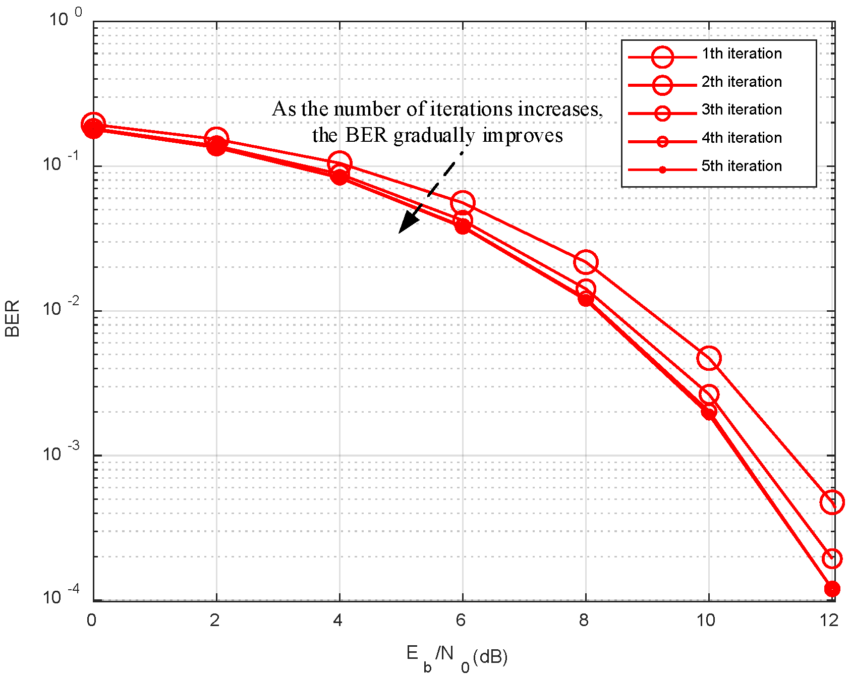
The above operations describe the single iteration process of TECC-MMSE-DFE in detail. Through the preset number of iterations P, BER is gradually improved.
3.2. Computational Complexity
We assume that when the complexity is the sum of high-order and low-order terms, the complexity of the low-order terms can be ignored. Based on this principle, we have provided simplified estimates of the complexities of various algorithms, as shown in
Table 2. The complexity of MAP is the highest, being exponential. Matrix inversion constitutes the major computational load in MMSE-DFE, bidirectional MMSE-DFE (Bi-MMSE-DFE), and TECC-MMSE-DFE. Bi-MMSE-DFE involves bidirectional processing. Hence, its complexity is double that of MMSE-DFE. Due to the presence of iterations, the complexity of TECC-MMSE-DFE is related to the number of iterations P. Meanwhile, VSD-BP mainly consists of linear operations (low-order), so its contribution to complexity can be disregarded. Therefore, the computational load of TECC-MMSE-DFE is 2P times that of MMSE-DFE. In practical applications,
P is generally set to less than 10 iterations, so compared to MMSE-DFE, the complexity of TECC-MMSE-DFE slightly increases but is still acceptable.
The current application scenario is underwater acoustic communication. The underwater sound wave propagation speed is slow, and the bandwidth is narrow, which makes the communication rate slow and time-delayed, making underwater acoustic communication less stringent in terms of real-time requirements. For example, the communication can be carried out by storing the entire signal and then demodulating it and decoding it by running the demodulation program on the computer.
5. Experiments of Underwater Acoustic Communication
In this section, the performance of TECC-MMSE-DFE in underwater acoustic communication is demonstrated, analyzed, and compared with that of MMSE-DFE and Bi-MMSE-DFE by a sea trial.
5.1. Experimental Setup
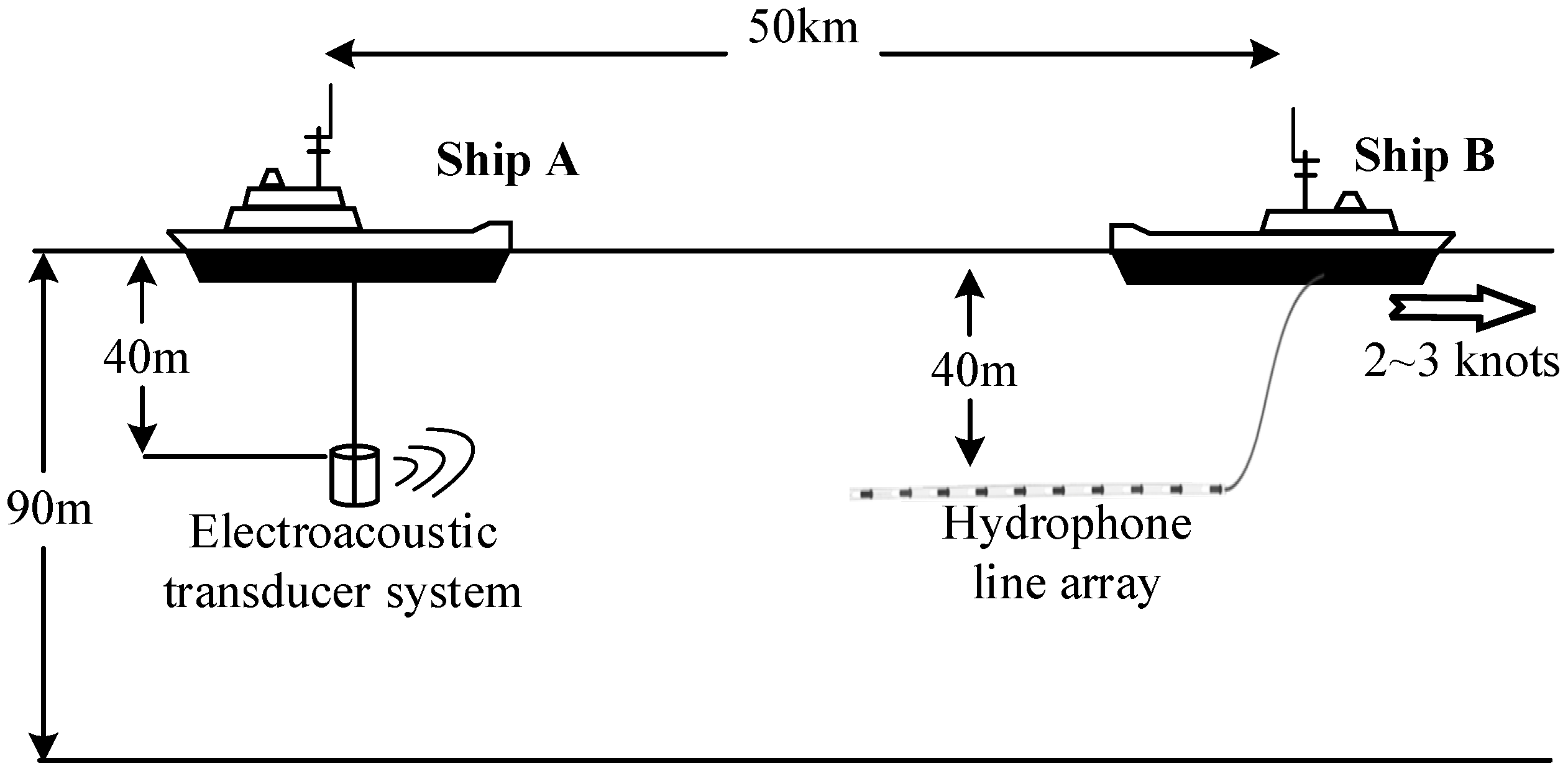
The sea trial involving two experimental ships in the South China Sea was held in October 2022. As shown in
Figure 8, Ship A was equipped with the software and hardware required for the electroacoustic transducer system at the source level of 175 dB. Ship A served as the transmitter of the communication and sent the modulated acoustic signal. Ship B was roughly 50 km from Ship A and equipped with the software and hardware required for the hydrophone line array, moving at a speed of about 2~3 knots. Ship B received the acoustic signal using a hydrophone and then demodulated the communication data using the equipment on board.
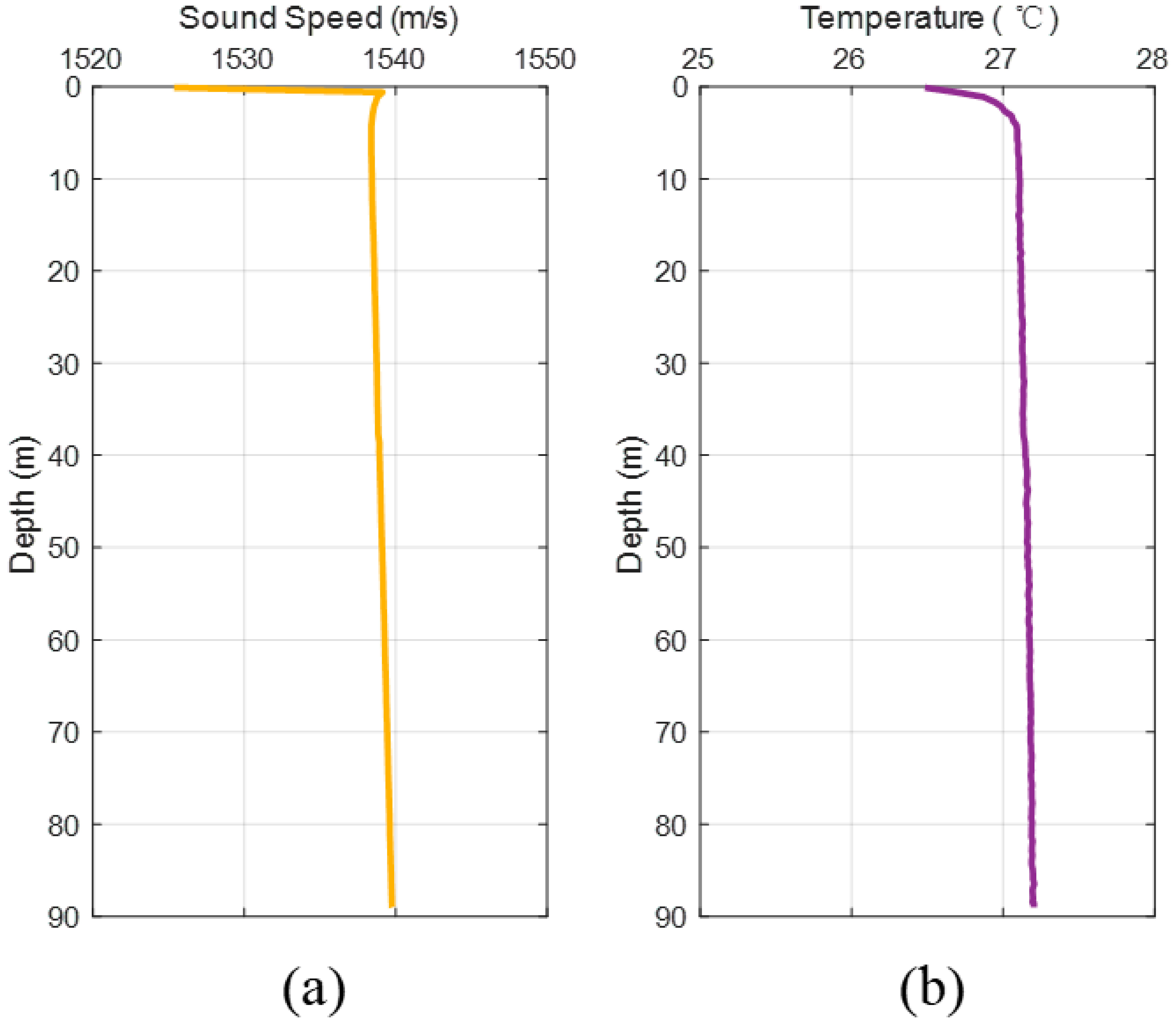
The sound speed profile and temperature profile are shown in
Figure 9. Since seawater temperature does not change significantly with distance, the sound speed shows a characteristic of approximately isosonic velocity gradient, which is conducive to the propagation of sound waves over long distances underwater.
In this communication experiment, the carrier frequency is 400 Hz, the baud rate is 100 symbols/s, and the modulation is BPSK. For time synchronization and wideband Doppler estimation, two segments of linear frequency modulation (LFM) signals are placed at the front and back ends of the communication signal, respectively. They are separated from the BPSK signal by a guard interval. To solve the forward channel h and reversed channel hTR, two training sequences are placed at the front end and back end of BPSK, respectively.
Due to long-distance propagation, the received signal is very weak. Therefore, time-domain beamforming is used to improve the signal-to-noise ratio while converting multi-channel data into single-channel data [
30]. In the time synchronization operation, normalized matched filtering of the LFM signal is used to determine the time of arrival [
31]. In the Doppler estimation and compensation operation, the time interval between two LFM segments is used to determine the Doppler factor, and then resampling is applied to the BPSK signal [
32]. In channel estimation, the least squares method is used, where
h is solved by the first training sequence, and
hTR is solved by the second training sequence. Although there are many advanced channel estimation methods, this paper mainly focuses on the improvement of analysis equalization technology, so we fixed a channel estimation method for comparison.
5.2. BER Performance
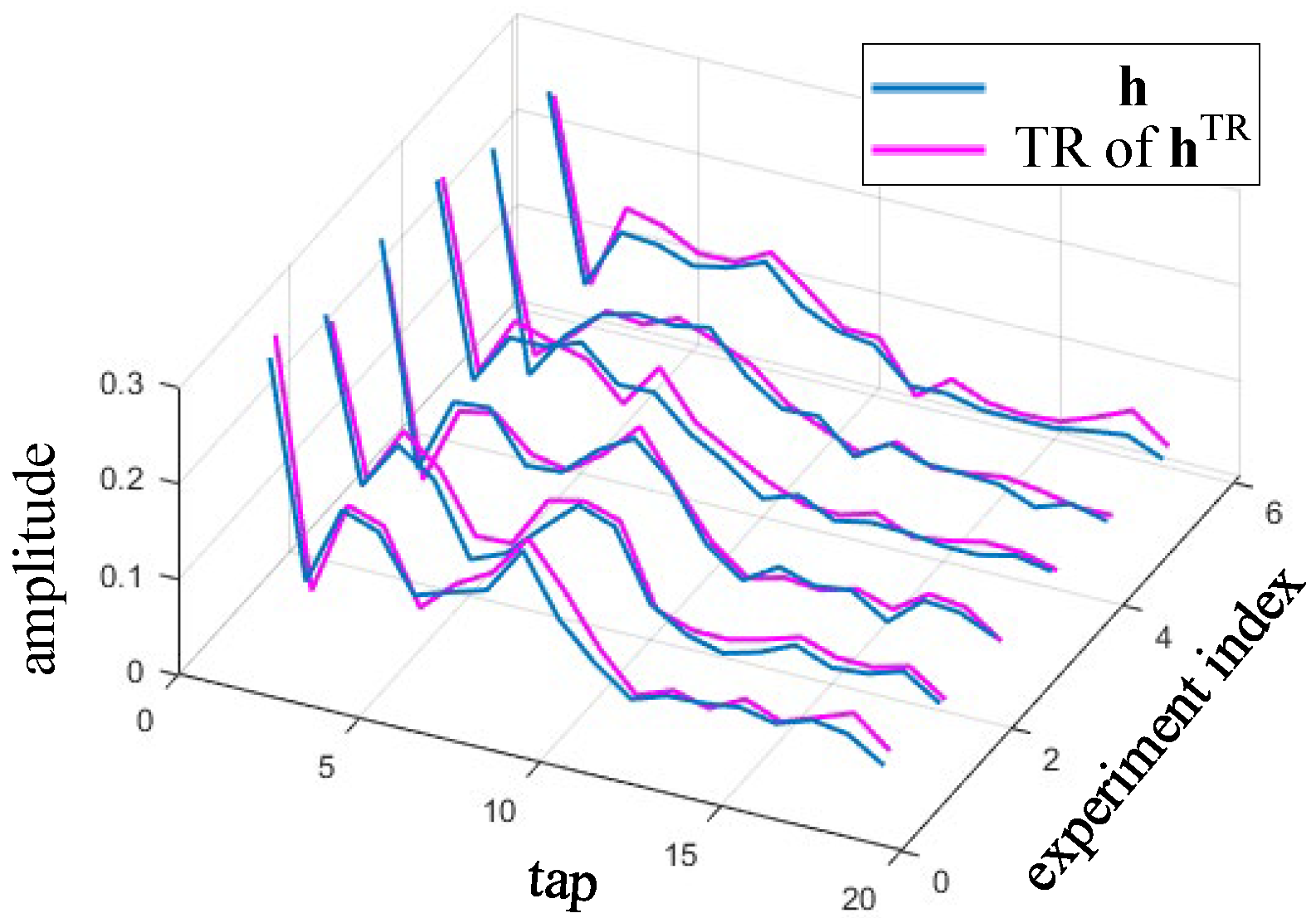
Through the training sequence and channel estimation, the forward channel and the reverse channel are obtained. As shown in
Figure 10, it can be observed that the front and rear channels are very similar. At this time, it can be approximated as a time-invariant channel. This is because the main time variation is removed by the resampling step. In the forward equalization branch,
h estimated from the first training sequence is used. However,
hTR is not obtained from
h but is estimated from the second training sequence.
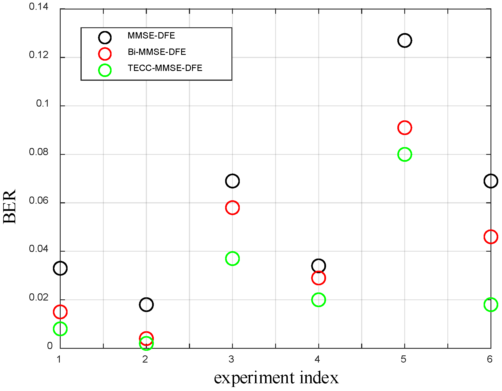
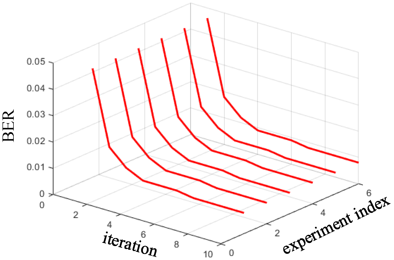
The following performance results are obtained with six experiments. We observe the following from
Figure 11 and
Figure 12.
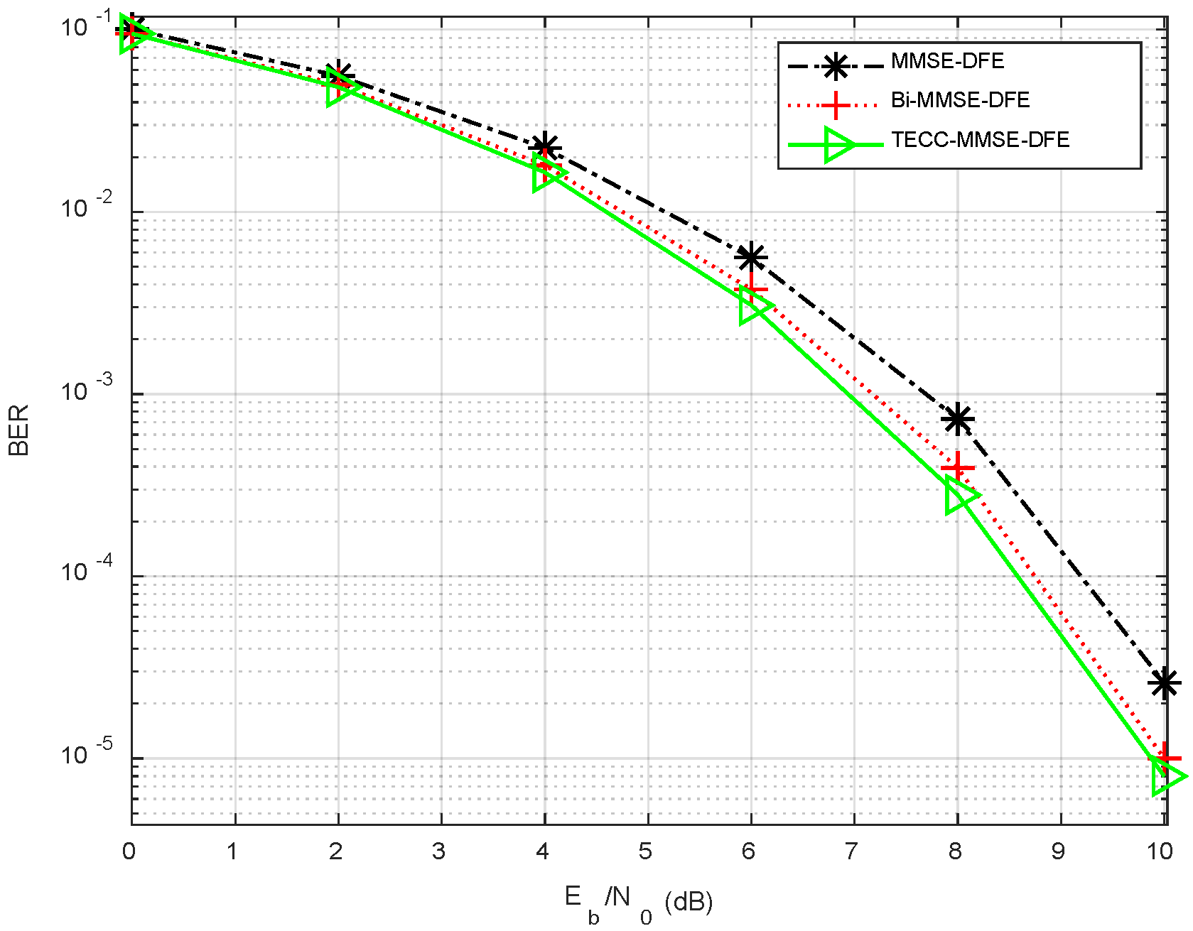
- (1)
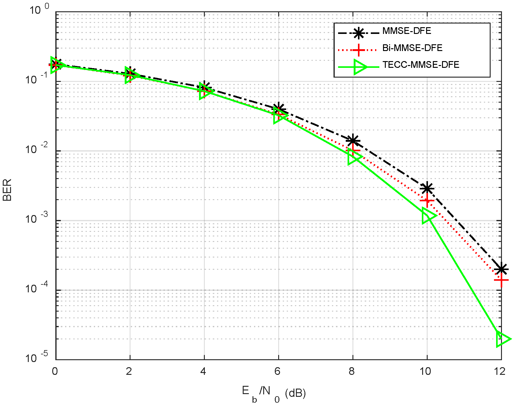
The BER of MMSE-DFE is the largest, and it can reach 0.13 in the most severe cases.
- (2)
Compared with MMSE-DFE, Bi-MMSE-DFE can further reduce the bit error rate through bidirectional processing.
- (3)
The BER of TECC-MMSE-DFE is the smallest. The BER is gradually reduced through iterative processing and becomes stable after three to four iterations.
The experimental results of underwater acoustic communication show that when TECC-MMSE-DFE is applied to actual communication systems, the BER performance can still be significantly improved. Therefore, TECC-MMSE-DFE has obvious engineering significance.
The data analysis here adopts a simple time-invariant channel estimation method, and the equalization operates according to the symbol interval. Therefore, it can be expected that TECC can further improve the bit error rate through a more accurate time-varying channel tracking method combined with a fractional interval equalizer.


