1. Introduction
As a core power unit in marine resource exploration, underwater engineering operations, and national defense equipment, the hydrodynamic performance and acoustic stealth characteristics of underwater propulsion systems directly determine the operational capability and environmental adaptability of submersible vehicles. With the rapid advancement of deep-sea exploration technologies, high-performance vessels, and underwater unmanned systems (UUVSs), conventional propellers are increasingly constrained by performance bottlenecks due to cavitation effects and noise issues. In particular, under the strategic guidance of the “Dual Carbon” objectives, the International Maritime Organization (IMO)’s mandatory requirements for the Energy Efficiency Existing Ship Index (EEXI) and underwater equipment noise emissions have further driven technological innovations in propulsion systems towards enhanced efficiency, noise reduction, and intelligentization. In this context, toroidal propellers have emerged as a key research direction in high-efficiency, low-noise propulsion design, demonstrating significant advantages in improving propulsion efficiency, reducing turbulent fluctuating noise, and suppressing cavitation. Consequently, the development of this novel propulsion technology holds strategic significance for reducing maritime carbon emissions, preserving marine acoustic ecology, and enhancing the stealth penetration capabilities of defense equipment. The research outcomes will substantially promote the coordinated realization of green shipping technological advancements and the strategic goals of building China into a maritime power.
At present, hydrodynamic research on toroidal propellers remains in the theoretical exploration and engineering validation stages, with critical gaps in understanding their propulsion mechanisms and unsteady cavitating flow characteristics. In terms of engineering applications, Sharrow Marine proposed a patented toroidal propeller design in 2018 [
1] and developed corresponding commercial products by 2023. From a theoretical exploration perspective, a research team at the Massachusetts Institute of Technology (MIT) investigated the feasibility of applying toroidal propellers in aerospace, experimentally validated their noise reduction performance advantages, and filed a related patent [
2]. Regarding theoretical modeling, Ye et al. established a three-dimensional geometric characterization framework for toroidal propellers by defining key geometric parameters, including the axial pitch, outer inclination angle, side rake angle, and vertical tilt angle [
3].
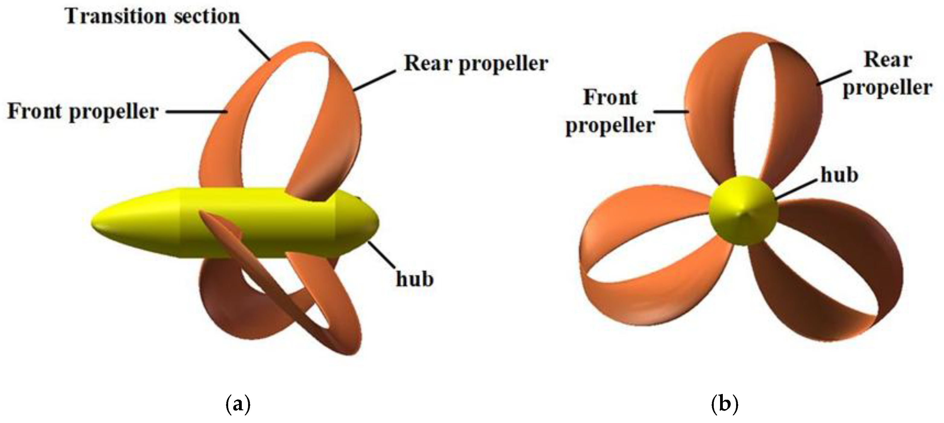
The innovative structure of the toroidal propeller can be conceptualized as a synthesis of tip-loaded and tandem propellers. A tip-loaded propeller (CLT) is characterized by an end plate at the blade tip, which is curved to physically constrain eddy current leakage at the blade tip, thereby significantly reducing ship noise and exciting forces while enhancing propulsion efficiency [
4]. Chang Xin et al. utilized the Delayed Detached Eddy Simulation (DDES) method to investigate the wake field and tip vortex characteristics of a propeller [
5]. Chao Wang et al. examined the hydrodynamic characteristics of CLT propellers using Large Eddy Simulation (LES), identifying a novel mutual induction mechanism for wake instability in CLT propellers [
6]. Gaggero analyzed the flow fields of both conventional and “new-generation” CLT propellers under varying load conditions through Improved Delayed Detached Eddy Simulation (IDDES) [
7]. Ebrahimi employed the Reynolds-Averaged Navier–Stokes (RANS) numerical method to study the impact of different end-plate geometries on the performance of five-blade B-series propellers with positive and forward inclination [
8].
A tandem propeller system constitutes a propulsion configuration wherein two conventional propellers are coaxially mounted on a common tail shaft, rotating synchronously in identical directions while maintaining a prescribed axial separation distance [
9]. Du Xiaoxu et al. numerically simulated and analyzed the cavitation performance of tandem propellers, revealing comparable cavitation characteristics to single propellers. However, under specific advance coefficient and cavitation number conditions, enhanced cavitation phenomena were observed in the aft propeller compared to its forward counterpart. Notably, cavitation instabilities were found to diminish with increasing advance coefficients or cavitation numbers [
10]. Yao et al. investigated the hydrodynamic performance of a novel canard-wing-configured tandem propeller using RANS methodologies, conducting comparative analyses against conventional tandem propeller architectures [
11]. Varghese et al. demonstrated, through the Vortex Lattice Lifting Line Method (VLLM) with lifting surface corrections, that geometric parameter optimization—particularly the pitch distribution derived from the VLLM—effectively eliminated adverse pressure distributions near the blade root regions of aft-positioned propellers [
12].
Currently, the application of Computational Fluid Dynamics (CFD) methodologies for hydrodynamic performance prediction has become an indispensable methodological paradigm in the design of novel propulsion systems. Researchers selectively employ distinct modeling frameworks to analyze propeller performance, balancing computational accuracy and efficiency based on specific investigative objectives [
13,
14,
15,
16]. Sikirica et al. evaluated the predictive accuracy of realizable
k-ε and SST
k-ω turbulence models in assessing marine propeller performance [
17]. Furthermore, Baltazar et al. leveraged RANS solvers to predict propeller performance under open-water conditions across varying Reynolds numbers [
18]. Hu Jian et al. conducted an investigation into the unsteady hydrodynamic performance of contra-rotating propellers (CRPs) in uniform flow conditions through numerical simulations employing a RANS solver integrated with an SST
k-ω turbulence model [
19]. To sum up, comparative analyses of CFD methodologies for propeller studies demonstrate that the synergistic implementation of Moving Reference Frame (MRF) techniques with RANS formulations demonstrates superior efficacy for rapid design iterations, whereas the sliding mesh (SM) approach exhibits enhanced capability in resolving transient flow characteristics with temporal precision.
In summary, there is limited research on toroidal propellers. This paper will establish a numerical simulation model to analyze their hydrodynamic performance, flow field, and vortex structure characteristics, aiming to explore the propulsion mechanism of toroidal propellers and provide theoretical support for the development of this technology.
4. Numerical Calculation
4.1. Numerical Validation and Grid Independence Test
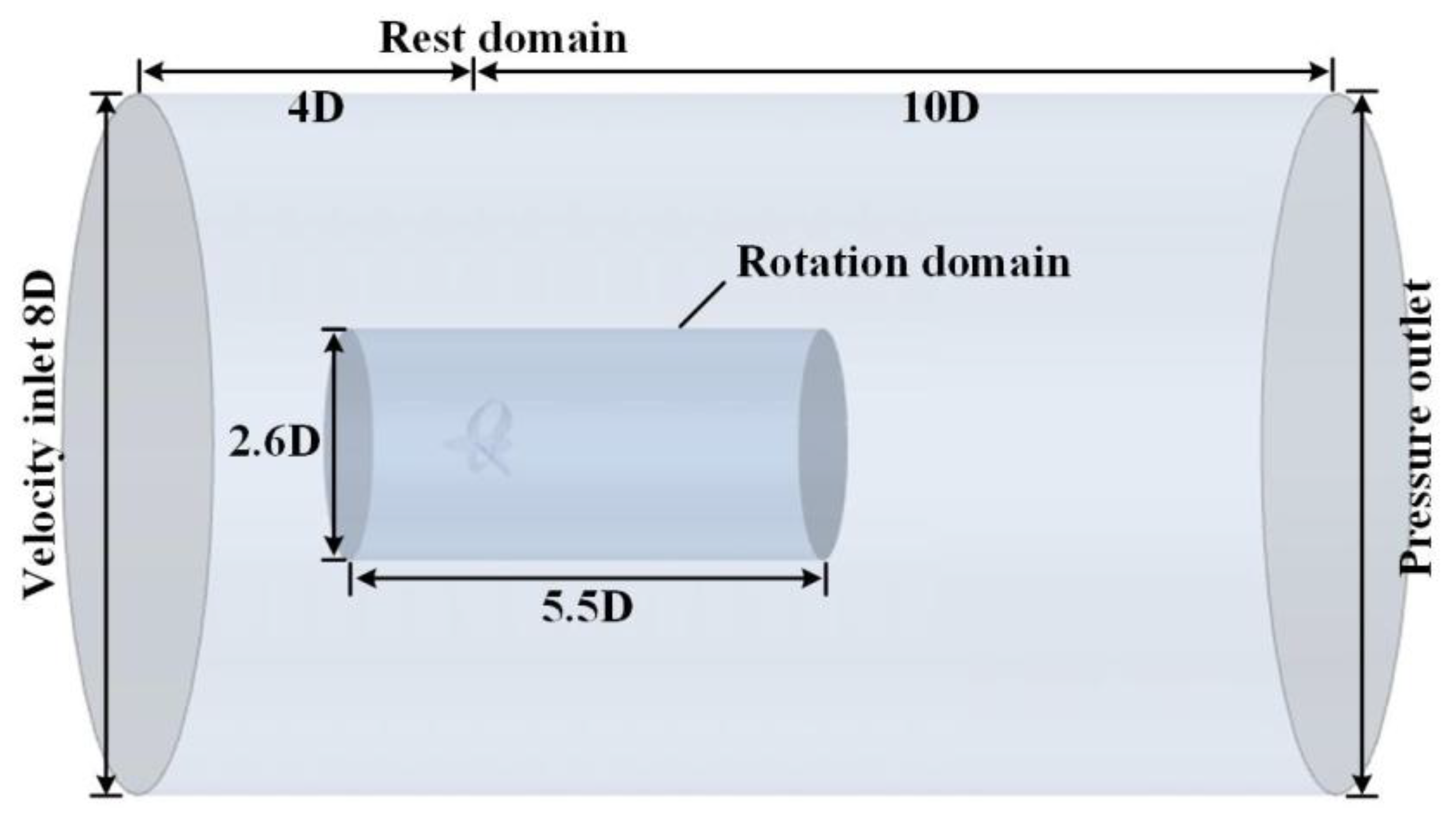
To ensure the reliability of the numerical methodology for predicting the hydrodynamic performance of propellers, experimental validation is conventionally employed for validation. Given the lack of publicly available experimental data for toroidal propellers as a novel propulsion system, this study adopted the extensively validated E779A standard propeller as the benchmark for methodological validation. The E779A propeller with a diameter
D = 0.27 m was selected for systematic numerical validation within the advance coefficient range of
J = 0.3–0.7 using 7.65 million grid cells after grid independence validation, while maintaining identical computational domain configuration, meshing strategy, turbulence model (SST
k-ω), and motion parameter settings with the toroidal propeller. As demonstrated in
Figure 4, comparative analysis between the numerical results and experimental measurements for the thrust coefficient
KT and the torque coefficient 10
KQ reveals strong congruence, with maximum relative errors confined within 5%. This validation protocol conclusively establishes the accuracy and reliability of the adopted numerical framework, thereby providing a robust methodological foundation for subsequent hydrodynamic investigations of toroidal propellers.
To minimize the impact of mesh size on numerical calculation results, this paper conducted a mesh independence analysis at advance coefficients of
J = 0.4, 0.8, and 1.2.
Table 2 presents the thrust coefficient
KT and torque coefficient 10
KQ for coarse, medium, and fine mesh configurations. As shown in
Table 3, the maximum rate of change is 6.5%. The increase in mesh density has a minimal effect on the calculation of the propeller’s thrust and torque coefficients. Therefore, to balance computational accuracy and cost, a mesh size of 6.86 million cells is deemed sufficient to meet the calculation requirements.
4.2. Hydrodynamic Performance Prediction of Toroidal Propeller
A systematic multi-condition numerical investigation of the toroidal propeller’s open-water hydrodynamic performance was conducted utilizing the RANS methodology coupled with the SST
k-ω turbulence closure model.
Figure 5 illustrates the evolution laws of the thrust coefficient
KT, torque coefficient
KQ, and propulsion efficiency
η under varying advance coefficients. These parameters are defined as follows:
The advance coefficient of the propeller is:
where
T represents the total thrust (N) exerted by the toroidal propeller,
Q denotes the total torque generated by the toroidal propeller (N·m),
signifies the density of water (kg/m
3),
n indicates the rotational speed (r/s),
D corresponds to the diameter of the propeller (m), and
VA represents the advance speed (m/s).
Figure 5.
Hydrodynamic performance curve of the toroidal propeller.
Figure 5.
Hydrodynamic performance curve of the toroidal propeller.
As illustrated in
Figure 5, both the thrust coefficient
KT and the torque coefficient
KQ exhibit a nonlinear decreasing trend as the advance coefficient
J increases. The propulsive efficiency
η shows continuous improvement within the range of
J = 0.2 to 1.1, reaching its peak between
J = 1.1 and 1.2, after which it decreases with further increases in the advance speed coefficient. Compared to traditional propellers, the highest efficiency point for toroidal propellers corresponds to higher speed coefficients, which is advantageous for enhancing the design speed of underwater vehicles. Moreover, the efficiency curve demonstrates a gradual attenuation near its peak value, allowing the underwater vehicle to maintain high efficiency even when operating speeds fluctuate around the design point. Consequently, the underwater vehicle can achieve greater efficiency across a broader range of speeds. Additionally, compared to conventional propellers, toroidal propellers provide superior thrust at lower speed coefficients while also increasing torque, thereby offering performance advantages in applications with limited diameter.
4.3. Surface Pressure Distribution Characteristics of the Toroidal Propeller
Given that the toroidal propeller attains peak propulsive efficiency within the advance coefficient range of
J = 1.0–1.2, the operational condition at
J = 1.1 was selected for a detailed hydrodynamic force analysis.
Figure 6 presents the pressure distribution of the toroidal propeller under this specific advance coefficient.
Figure 6a delineates the pressure distribution on the blade back of the propeller, while
Figure 6b illustrates the pressure profile on the blade face.
As depicted in
Figure 6, under the operational condition of an advance coefficient of
J = 1.1, the toroidal propeller exhibits distinct pressure distribution characteristics: a low-pressure zone forms on the blade back, while a high-pressure zone dominates the blade face. This pressure gradient constitutes the primary source of propulsive force. Notably, the pressure differential across the front propeller blade significantly exceeds that of the rear propeller blade, resulting in dominant thrust generation by the front propeller.
On the blade back, the pressure distribution demonstrates a progressive decrease from the blade root to the tip, coupled with gradual pressure recovery from the leading edge to the trailing edge. A pronounced low-pressure band is observed along the leading-edge periphery, consistent with predictions from cavitation inception theory, indicating elevated cavitation susceptibility in this region. Comparative analysis reveals that the spatial extent and pressure intensity of the low-pressure zone on the front propeller blade substantially surpass those on the rear propeller blade.
On the blade face, peak pressure values manifest at the leading edge near the tip of the front propeller blade, exhibiting an increasing pressure gradient from root to tip. Particularly, the transition region between the front and rear propellers exhibits significant pressure gradients, while multiple strip-like low-pressure zones emerge along the leading edge of the pressure side. This phenomenon critically influences both the cavitation performance and structural integrity of the toroidal propeller. Comparative analysis further confirms that the spatial coverage and pressure magnitude of the high-pressure region on the front propeller blade markedly exceed those on the rear propeller blade.
Through CFD calculation, the pressure distribution data on the propeller surface can be obtained. The focus of the comparative analysis is the section at r/R = 0.5, 0.7, and 0.9, where R is the radius of the propeller and r is the radius at a certain position of the propeller, as shown in
Figure 7.
In
Figure 7, the vertical axis
CP represents the pressure coefficient, which is defined as:
where
P is the pressure value and
VW is the tangential velocity at r/R.
In
Figure 7, it can be observed that the front propeller exhibits a significant pressure difference at the leading edge, generating substantial thrust, while the rear propeller demonstrates high pressure values at the leading edge but with minimal pressure differential variation.
To further investigate the influence of varying advance coefficients on the pressure distribution of the toroidal propeller,
Figure 8 presents the pressure distribution on both the blade back and blade face under advance coefficients
J = 0.3, 0.6, 0.9, and 1.2.
Based on the pressure distribution characteristics illustrated in
Figure 8a, it can be observed that the blade back pressure field of the propeller exhibits an overall upward trend with an increasing advance coefficient
J. The front propeller blades consistently demonstrate lower pressure magnitudes compared to the rear propeller blades, with an increasing pressure gradient distributed from the leading edge to the trailing edge. Under low
J conditions, the minimum pressure region on the front propeller blades extends from the blade root to the transition segment. As
J increases, this low-pressure zone progressively contracts and ultimately concentrates within the transition segment.
As shown in
Figure 8b, the blade face pressure field of the toroidal propeller displays a global downward trend with rising
J, where the front propeller blades maintain higher pressure magnitudes than the rear counterparts, accompanied by a decreasing pressure gradient from the leading edge to the trailing edge. Pressure maxima are predominantly localized near the leading edge of the front propeller blades. With increasing
J, the spatial extent of this high-pressure region gradually diminishes and eventually shifts toward the leading edge of the transition segment.
4.4. Evolution Characteristics of the Velocity Field in the Toroidal Propeller
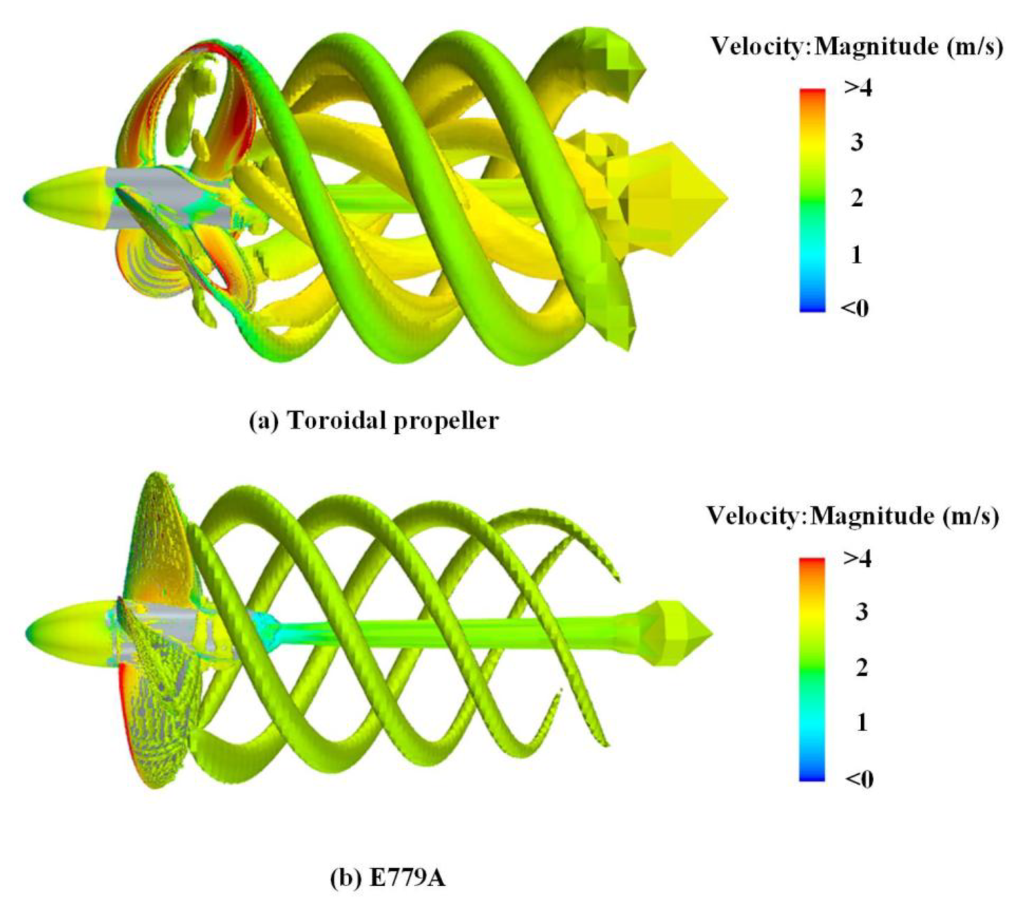
To investigate the flow field characteristics of the toroidal propeller, a comparative analysis of its velocity field with the E779A propeller was conducted at an advance coefficient of
J = 1.1, as illustrated in
Figure 9.
As evidenced by
Figure 9, under identical operational conditions, the toroidal propeller exhibits velocity maxima concentrated within the transition section, whereas the E779A propeller demonstrates peak velocities localized near the blade tip and root regions. The front propeller of the toroidal configuration induces a pronounced suction effect, significantly accelerating the incoming flow prior to blade interaction. A distinct high-velocity region persists between the front and rear propellers, with the fluid undergoing further acceleration through the rear propeller passage. The comparison shows that the fluid only accelerates once through the E779A propeller, and the velocity field is relatively uniform.
Figure 10 delineates the velocity distribution of the toroidal propeller across varying advance coefficients
J. A persistent low-velocity zone is identified upstream of the hub. Within the axial range
X = −0.1–0.05, fluid acceleration induced by the front propeller’s suction effect generates a high-velocity region near the hub between the front and rear propellers. The flow field maintains dominant high velocities across
X = 0.05–0.4, though a banded low-velocity zone emerges downstream of the hub. Notably, the velocity magnitude within high-velocity regions exhibits significant enhancement with increasing
J. Under low
J conditions, the wake downstream demonstrates turbulent characteristics with lateral divergence tendencies. As
J increases, the wake progressively contracts toward the central axis, while longitudinal velocity profiles homogenize.
4.5. Vortical Dynamics Characteristics of the Toroidal Propeller
Vortex structures constitute one of the critical hydrodynamic features within propeller flow fields. To elucidate the propulsion mechanisms of the toroidal propeller, comparative analyses of wake vortices between the toroidal and E779A propellers were conducted employing the Q-criterion, as depicted in
Figure 11.
Figure 11 illustrates the vortex structure distributions of the toroidal propeller and the E779A propeller. The vortical structures surrounding the propellers serve as critical indicators for understanding hydrodynamic flow evolution. The vorticity field of the toroidal propeller is divided into three distinct components: the tip vortices generated by the front propeller, the rear propeller-induced vortices, and the hub vortex originating from the hub region. In contrast, the E779A propeller exhibits only blade-induced vortices and a hub vortex.
To investigate the influence of the advance coefficient
J on the wake vortical structures of the toroidal propeller,
Figure 12 presents Q-criterion isosurface visualizations and velocity distributions at
J = 0.3, 0.6, 0.9, and 1.2. The vortical structures are visualized using an isosurface threshold of
Q = 150/s
2.
In
Figure 12, under the low advance coefficient condition
J = 0.3, the toroidal propeller exhibits complex vortical structures in proximity to its blades. The toroidal propeller blade system, comprising the front propeller, rear propeller, and transition section, generates significant vortical structures in the front propeller region due to its unique geometric configuration. Specifically, the mid-section of the front propeller produces vortices that transiently merge with the tip vortices of the front propeller. Additionally, the front propeller tip simultaneously generates two vortices of differing scales—a larger primary vortex and a smaller secondary vortex. The smaller vortex dissipates shortly after formation, leaving the larger tip vortex as the dominant component of the toroidal propeller’s wake.
A particularly distinctive feature is the merging of tip vortices shed from one blade with those generated by adjacent blades, followed by downstream development. In contrast, the mid-section vortices of the front propeller and the vortices generated by the rear propeller remain independent, evolving separately as they propagate downstream.
The vortical structures exhibit distinct characteristics as the advance coefficient J varies. Under higher advance coefficients, the tip vortices of the front propeller and the vortices generated by the rear propeller maintain a helical distribution without merging. As J increases, the mid-section vortices of the front propeller gradually weaken. The velocity characteristics of the vortical structures demonstrate significant differences across advance coefficients. At low J, the internal vortices within the front propeller exhibit substantially higher velocities compared to the external tip vortices. However, as J increases, the velocity of the tip vortices rises accordingly, thereby reducing the velocity disparity between internal and external regions.
To elucidate the evolution of the toroidal propeller’s vorticity field, detailed analyses were conducted at J = 0.3, 0.6, 0.9, and 1.2.
Figure 13 illustrates the evolution of the vorticity field in the toroidal propeller across varying advance coefficients
J. Under all operational conditions, sheet-like vortices of varying scales emerge downstream of the blade tips, with vorticity magnitude decaying as distance increases. This phenomenon is attributed to rotational effects within the slipstream region. The research results clearly reveal the influence law of the advance coefficient
J on the vorticity field of toroidal propellers: as the J value increases, the vorticity intensity decreases significantly while demonstrating distinct periodic variation characteristics.
The toroidal propeller features a distinct hub vortex, with vorticity downstream of the hub manifesting as a jet-like structure. The peak vorticity magnitude occurs in the region X = 0.15–0.4 behind the hub. Notably, the intensity of the hub vortex remains relatively insensitive to changes in J.


