Article

Dynamic Modeling and Experimental Validation of Shock Isolation Performance for Shipborne Stewart-Platform-Based Bumper

College of Marine Equipment and Mechanical Engineering, Jimei University, Xiamen 361021, China
*
Author to whom correspondence should be addressed.
J. Mar. Sci. Eng. 2025, 13(6), 1007; https://doi.org/10.3390/jmse13061007
Submission received: 26 April 2025 / Revised: 15 May 2025 / Accepted: 21 May 2025 / Published: 22 May 2025
(This article belongs to the Section Ocean Engineering)

Abstract

:
The Stewart-platform-based bumper plays a critical role in shipborne strap-down inertial navigation systems (SINSs), effectively mitigating shock-induced disturbances to ensure measurement accuracy. Dynamic modeling for the bumper under a huge impact is a key issue in predicting the shock isolation performance of the bumper. In this paper, the dynamic modeling of shock isolation performance for Stewart-platform-based bumpers under huge impacts is proposed and validated experimentally. Firstly, a model of a Stewart-platform-based bumper is established considering the geometric configuration and dynamic parameters of the bumper by calculating the Jacobian matrix, stiffness matrix, damping matrix and mass matrix. Secondly, an analytic simulation of the impact is presented based on the measured impact acceleration, and the impact force on the load is derived according to the non-displacement assumption in the impact stage. Then, the Lagrangian formulation was systematically applied to establish governing equations characterizing the six-degree-of-freedom (DOF) dynamics of the bumper, incorporating both inertial coupling effects and nonlinear shock energy dissipation mechanisms. Afterwards, dynamic equations were solved via the Runge–Kutta method to obtain the theoretical results. Finally, the proposed dynamic modeling and shock isolation performance analysis method was validated via impact experiments for the bumper.

1. Introduction

As the central sensor in marine GPS/SINS (global positioning system/strap-down inertial navigation system) integrated navigation architectures, SINSs provide autonomous full-state motion parameter estimation, establishing the industry-standard solution for ship attitude determination [1,2,3]. Despite advanced isolation systems, SINSs remain vulnerable to broad-spectrum vibration threats in marine environments, particularly high-g mechanical shocks (>40 g, 1–5 ms duration) from propeller cavitation, wave slamming forces and underwater explosion phenomena [4,5]. Experimental evidence demonstrates that high-g mechanical shocks induce catastrophic performance degradation in SINSs [6]. To address this critical vulnerability, a vibration isolation system must be strategically implemented within the shock transmission pathway connecting the SINSs and hull structure to dissipate impact energy prior to inertial sensor excitation.
The bumper for SINSs to deal with huge impacts is designed to absorb shock, while the restoration accuracy requirement of the bumper is stringent because of the high attitude accuracy of SINSs. Due to the significant advantages in terms of dynamic properties, load-carrying capacity, accuracy, stiffness and stability of Stewart platforms [7,8,9], Stewart-platform-based bumpers have become prevalent in precision engineering applications, particularly exemplified by six-DOF electromagnetic active isolation systems designed for high-precision payload stabilization [10], a single-gimbal control gyro stabilization system with adaptive damping [11], a satellite-deployed six-DOF active micro-vibration isolation platform [12], a high-precision six-DOF vibration suppression system specifically engineered for orbital instrumentation [13] and other Stewart-platform-constructed bumpers.
For SINSs, reference [14] developed a Stewart-platform-based vibration isolation system that achieves dual objectives: (1) attenuating high-energy impact transmission, and (2) maintaining structural repositioning accuracy. The system’s kinematic architecture employs six symmetrically distributed damping struts, each incorporating dual spherical joints at terminal connections, thereby enabling full 6-DOF motion decoupling between the inertial measurement unit (moving platform) and vessel structure (static base). But reference [14] only focused on the geometric configuration optimal design for restoration accuracy and did not analyze the dynamic properties of the bumper. However, dynamic analysis for bumpers is a key issue in predicting the shock isolation performance of the bumper and optimal design for buffer bars. So, a dynamic analysis should be performed for the bumper.
More recently, studies of dynamic analyses for Stewart-platform-based parallel mechanisms have been the focus of plenty of scholars. Yang et al. [15] established a complete inverse dynamics model of the 6-DOF micro-vibration simulator using the Kane method. Paper [16] studied the dynamic response of a manipulator under specific external loads. Chen et al. [17] put forward a new scenario for the dynamic modeling of a Stewart platform parallel mechanism based on the transfer matrix method for linear multi-body systems. Bernal et al. [18] formulated a non-minimal coordinate dynamic modeling framework for parallel manipulators, employing redundant generalized coordinates to circumvent the singularity-induced computational instabilities inherent in conventional Lagrangian formulations. Shao et al. [19] proposed a finite and instantaneous screw based method for the dynamic modeling of a two-DOF parallel robot.
All dynamic analyses for Stewart-platform-based parallel mechanisms mentioned previously focused on the moving dynamic performance or vibration isolation performance of the platforms. However, there are significant differences between dynamic analyses of shock isolation performance under a huge impact and dynamic analyses of moving dynamic performance or vibration isolation performance [20,21]. Dynamic analyses of shock isolation performance should be separately investigated from studies of moving dynamic performances or vibration isolation performance for isolators. Shu et al. [22] studied the shock robustness of a head actuator assembly subjected to half-sine acceleration pulses. Harmoko et al. [23] analyzed the shock isolation performance of an operating hard disk drive in a harsh environment. Paper [24] presented an analytical model to obtain the response of a vibration absorber system under impulse excitation. Yan et al. [25] studied the shock isolation performance of a GAS isolator subjected to double-sided compensation half-sine shock input. He et al. [26] conducted a study on the analysis and design of the Stewart-platform-based parallel support bumper for an inertially stabilized platform. All of these studies of the shock isolation performance of absorbers proposed individual dynamic analysis methods according to the corresponding structures of absorbers.
As mentioned above, the Stewart platform is a complicated parallel mechanism and its shock isolation performance under a huge impact has not been studied completely. However, the shock performance analysis of the Stewart-platform-based SINS’s bumper is a key issue in predicting the performance of the bumper in the design and optimal design of buffer bars. In this paper, a new approach for the dynamic modeling and shock isolation analysis of the Stewart-platform-based SINS’s bumper under impact is proposed. The innovation points and new contributions of this study are as follows.
(1)
A dynamic model of a Stewart-platform-based bumper under impact is derived;
(2)
An experimental/analytical simulation of impact is established;
(3)
Dynamic analyses of the bumper considering the dynamic properties and impact condition are conducted.
The remainder of this paper is organized as follows. Section 2 gives an overview of the Stewart-platform-based SINS’s bumper, including the mechanism composition, anti-shock principle and mechanical configuration of the bumper. In Section 3, a model of the bumper is established first by calculating the Jacobian matrix, stiff matrix, damping matrix and mass matrix of the bumper; then, an analytic simulation of impact is presented based on the experimental measured impact acceleration, and the impact force on the load is derived according to the non-displacement assumption in the impact stage; and finally, dynamic equations of the bumper under impact are derived based on the model of the bumper and impact using the Lagrange method. Later, in Section 4, dynamic equations are solved by the Runge–Kutta method and an impact experiment is conducted to verify the proposed method for the dynamic modeling and shock isolation performance analysis of the bumper. Lastly, conclusions are given in Section 5.

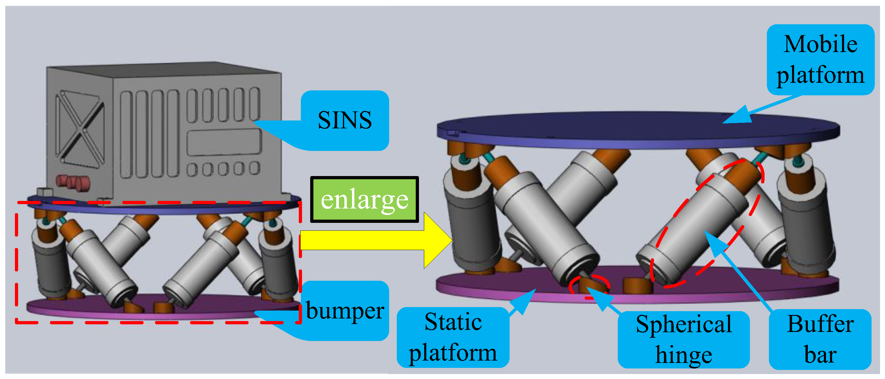
2. Stewart-Platform-Based Bumper

2.1. Anti-Shock Principle

Firstly, the system architecture was delineated through a Stewart-platform-based vibration isolation mechanism integrated with the SINS. Figure 1 illustrates the operational configuration where (1) the isolation assembly is rigidly anchored to the vessel’s structural deck, and (2) the SINS module is kinematically coupled to the platform’s upper mobile stage. Structurally, this 6-DOF isolation system comprises three principal subsystems: a base platform (fixed to the hull), a payload interface platform (the SINS mounting surface) and six identical damping struts arranged in dual tetrahedral configurations. Each strut incorporates two spherical joints at terminal connections, totaling twelve precision articulation points across the assembly [27]. The 6-SPS parallel kinematic architecture, by virtue of its hexapodal configuration with six independently controllable degrees of freedom [28], enables full-spectrum vibration isolation across all six spatial axes (surge, sway, heave, roll, pitch and yaw), effectively decoupling the SINS from hull-borne shock vectors propagating through the deck structure.
Figure 2 presents detailed cross-sectional and exploded views of a damping strut to elucidate the Stewart-platform-based isolation system’s shock mitigation mechanics. Each strut integrates two mechanically constrained helical compression springs with identical stiffness and damping coefficients, symmetrically arranged within precision-machined cylindrical housings. During shock transmission from the hull, struts execute controlled axial displacements along their principal axes, achieving kinetic energy dissipation through this three-stage thermodynamic conversion process. As a result, the anti-shock principle of the bumper is based on energy storage via the deformation of springs in buffer bars while shock occurs and energy dissipation via the damping of buffer bars to minimize the residual vibration when the shock has finished.

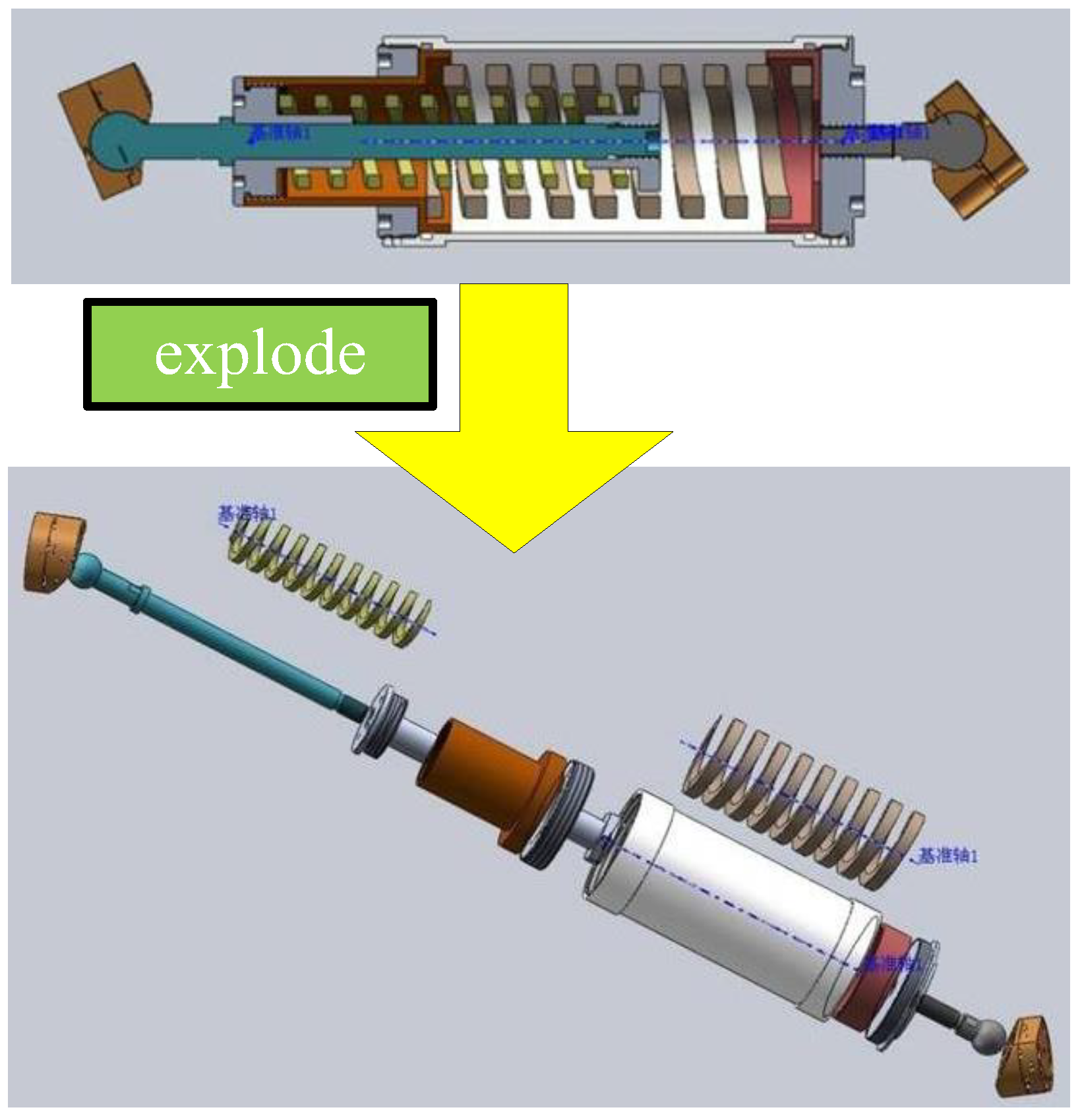
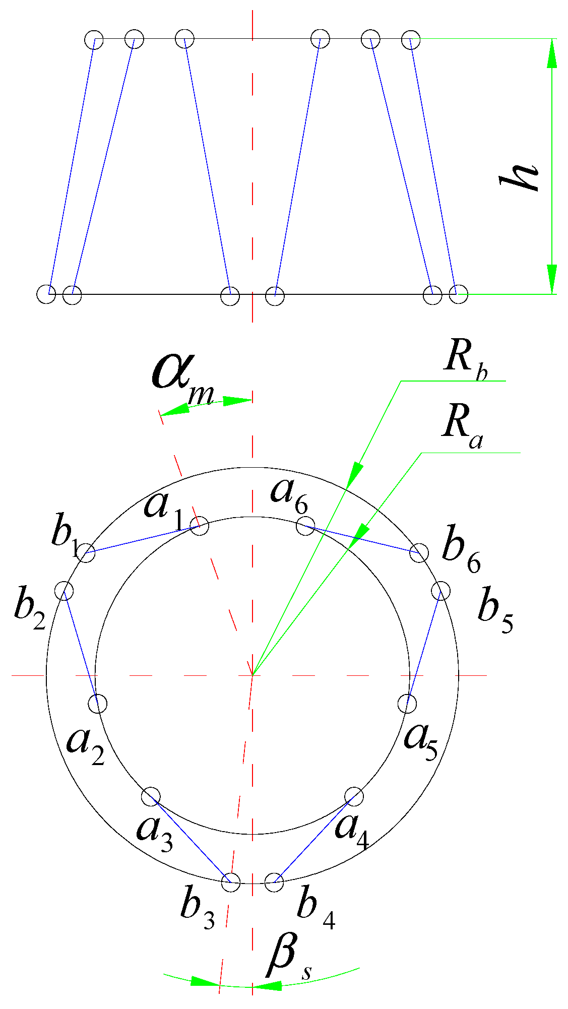
2.2. Mechanical Configuration

As shown in Figure 3, the mechanical configuration of the bumper depends on the structural parameters of the bumper, including height h , the radius of the static platform R b , the radius of the mobile platform R a , the half-flare angle of adjoining spherical hinge on static platform β s and the half-flare angle of the adjoining spherical hinge on the mobile platform α m . All structural parameters of the bumper were optimized in our previous work [14] for restoration accuracy and are listed in Table 1. The length of the buffer bar is 223 mm.

3. Dynamic Modeling

3.1. Dynamic Model of Bumper

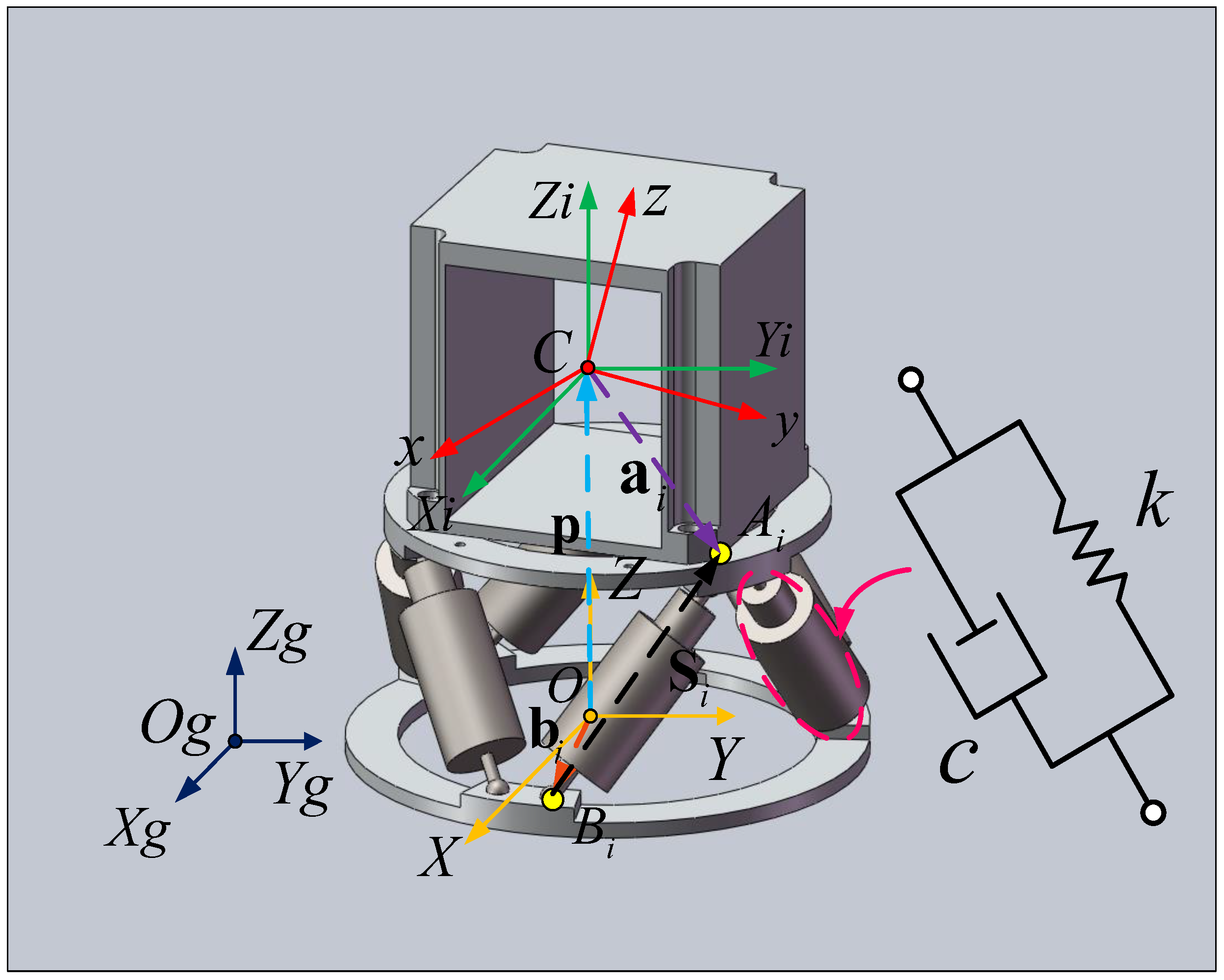
3.1.1. Coordinate Definition

To derive the dynamic equations of the bumper, kinematic reference frames and lumped parameter model of marine SINS isolation platform were established and are shown in Figure 4. O X Y Z is the static platform frame. C x y z is the load frame. C X i Y i Z i is the intermediate frame of load. O g X g Y g Z g is the ground frame.
Vector p = x p y p z p T denotes the position vector of point C in O X Y Z ; points A i ( i = 1 , 2 , , 6 ) are the center of the upper spherical hinges and vectors a i ( i = 1 , 2 , , 6 ) are the coordinates of the A i ( i = 1 , 2 , , 6 ) in C x y z ; points B i ( i = 1 , 2 , , 6 ) are the center of the lower spherical hinges and vectors b i ( i = 1 , 2 , , 6 ) are the coordinates of the B i ( i = 1 , 2 , , 6 ) in O X Y Z ; vectors S i ( i = 1 , 2 , , 6 ) are the vectors of each buffer bar, which spans from B i to A i in O X Y Z . The attitude of mobile platform related to static platform is defined as Euler angles Φ = α β γ T , in which mobile platform firstly rotates α around axis C X i , then rotates β around axis C Y i and finally rotates γ around axis C Z i . Moreover, vector q is the generalized coordinate of the mobile platform and can be written as follows.
q = p Φ T = x p , y p , z p , α , β , γ T .

3.1.2. Jacobian Matrix

Based on the kinematic reference frames illustrated in Figure 4, kinematic model was firstly set up to find the relationship between the mobile platform’s generalized velocity and the buffer bars’ velocities. Kinematic model could be written using the Jacobian matrix [29]. Jacobian matrix analysis for kinematics of the bumper is derived as follows.
S i can be expressed as follows.
S i = p + R a i b i ,
where R is the rotation matrix between C x y z and C X i Y i Z i if the Euler angle is small, and R can be written as follows.
R = 1 γ β γ 1 α β α 1 .
Both sides of Equation (2) are differentiated by time as follows.
S ˙ i = p ˙ + ω × R a i ,
where ω is the rotation angular velocity vector of mobile platform related to static platform.
We define s i ( i = 1 , 2 , , 6 ) as the unit vector of each buffer bar, and l i ( i = 1 , 2 , , 6 ) is set as the length scalar of each buffer bar. The differential of l i related to time can be rewritten as follows.
l ˙ i = s i T · S ˙ i .
Equation (4) is substituted into Equation (5), and then Equation (5) can be rewritten as follows.
l ˙ i = s i T · p ˙ + s i T · ( ω × R a i ) .
According to the computational formula for mixed products of three vectors, Equation (6) can be transformed as follows.
l ˙ i = s i T · p ˙ + ( c i × s i ) T · ω ,
where c i = R a i .
As i = 1 , 2 , , 6 , Equation (7) can be rewritten to matrix form as follows.
l ˙ = J q · q ˙ ,
where l is a vector constructed by all six length scalars of buffer bars, J q is the Jacobian matrix from 6-DOF movement of mobile platform to bidirectional linear displacements of buffer bars and l and J q can be expressed as follows.
l = l 1 l 2 l 3 l 4 l 5 l 6 T
J q = s 1 T ( c 1 × s 1 ) T s 2 T ( c 2 × s 2 ) T s 6 T ( c 6 × s 6 ) T 6 × 6 .
The workspace of bumper is nonsingular, so J q is a nonsingular matrix and J q 1 exists [30]. By substituting J q 1 into both sides of Equation (8), Equation (8) can be written as follows.
q ˙ = J q 1 · l ˙ = J l · l ˙ ,
where J l is the Jacobian matrix from bidirectional linear displacements of buffer bars to 6-DOF movement of mobile platform and J l = J q 1 .
When shock occurs or finishes, the movement of mobile platform related to static platform is small, so the changes in lengths of buffer bars are small. Finally, the Jacobian matrix when shock occurs or finishes can be ignored, according to Equation (10). Thus, Jacobian matrices J q and J l are regarded as constant matrices decided by static configuration of the bumper.

3.1.3. Stiffness Matrix and Damping Matrix

As shown in Figure 4, each buffer bar is modeled as a spring/damper consisting of a spring and a damper in parallel, and the stiffness and damping of the buffer bar’s model are k and c , respectively. Based on the Jacobian matrix, stiffness matrix and damping matrix of the bumper can be derived using the principle of virtual work. F k and F c are defined as the generalized forces on load due to elastic forces f k and damping forces f c of buffer bars, respectively. f k and f c can be expressed as follows.
f k = k · Δ l = k · Δ l 1 Δ l 2 Δ l 3 Δ l 4 Δ l 5 Δ l 6 T
f c = c · l ˙ = c · l ˙ 1 l ˙ 2 l ˙ 3 l ˙ 4 l ˙ 5 l ˙ 6 T .
For stiffness matrix, according to the principle of virtual work, the work of F k on tiny change of q is equal to the work of f k on small variation of l , as follows.
F k T · Δ q = f k T · Δ l .
Equations (8) and (12) are substituted into Equation (14), and Equation (14) can be written as follows.
F k = K · Δ q = ( k J q T J q ) · Δ q ,
where K is the stiffness matrix of the bumper and can be expressed as follows.
K = k J q T J q .
Similarly, C is the damping matrix of the bumper and can be expressed as follows.
C = c J q T J q .
Because Jacobian matrices J q and J l are regarded as constant matrices decided by static configuration of the bumper, stiffness matrix K and damping matrix C are also constant matrices relying on the static mechanism of the bumper.

3.1.4. Mass Matrix

It is essential to calculate the mass matrix for dynamic analysis of the bumper. The mass matrix of the bumper with respect to point O in frame O X Y Z can be written as follows [31].
M = m I 3 × 3 0 3 × 3 0 3 × 3 I O ,
where m is the mass of the load, I 3 × 3 is 3 × 3 identity matrix, 0 3 × 3 is 3 × 3 null matrix and I O is the inertial tensor with respect to point O in frame O X Y Z . Inertial tensor with respect to point C in frame C x y z is I C written as follows.
I C = I x x I x y I x z I x y I y y I y z I x z I y z I z z .
According to the parallel axis theorem and rotation transformation of coordinate systems, I O can be expressed using p = x p y p z p T , R and I C , as follows.
I O = R I x x + m ( y p 2 + z p 2 ) I x y + m x p y p I x z + m x p z p I x y + m x p y p I y y + m ( x p 2 + z p 2 ) I y z + m y p z p I x z + m x p z p I y z + m y p z p I z z + m ( x p 2 + y p 2 ) R T .
Moreover, the dynamic parameters of the model of the bumper are listed in Table 2.

3.2. Dynamic Model of Impact

An experimental/theoretical integrated method was used to simulate the impact on bumper analytically. Firstly, impact experiments were conducted and accelerometer was fixed on static platform to measure the real impact acceleration. Then, an analytic simulation was presented based on the experiment results to express the impact acceleration analytically. Finally, impact forces on the load were derived according to the non-displacement hypothesis for load in impact stage.

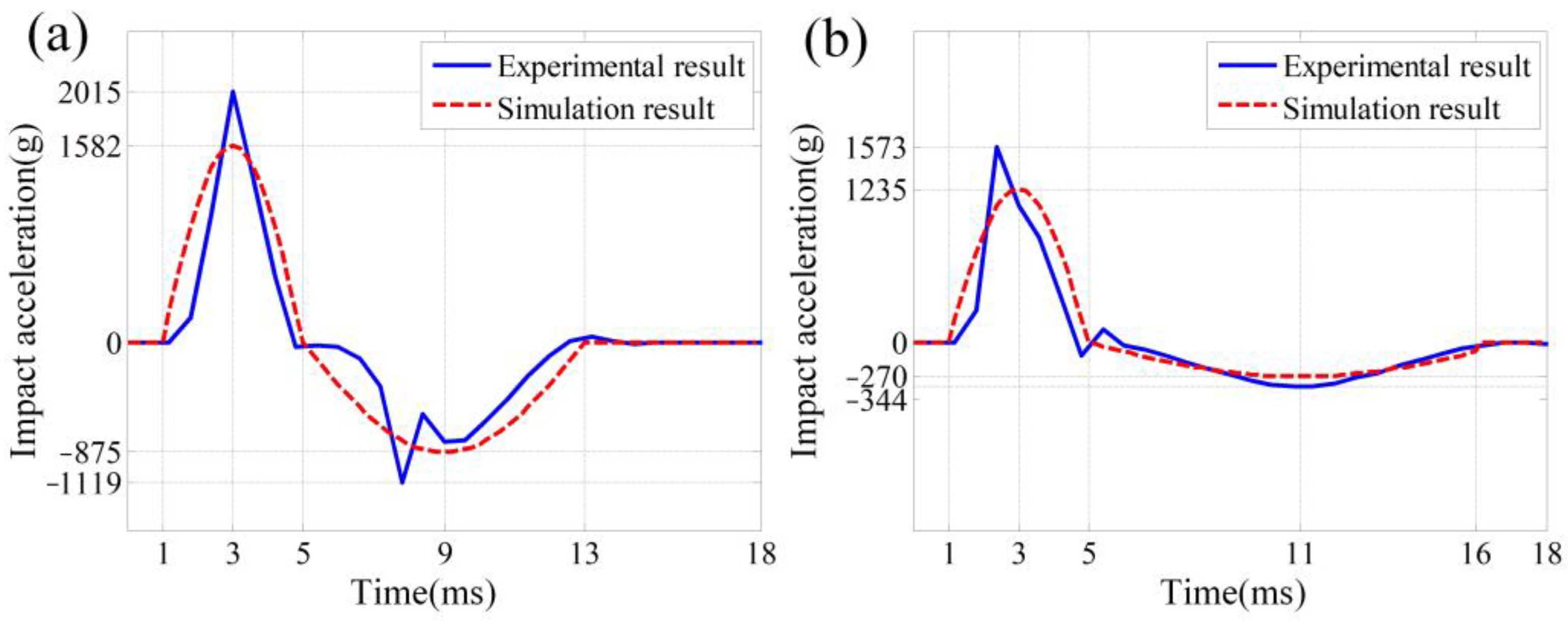
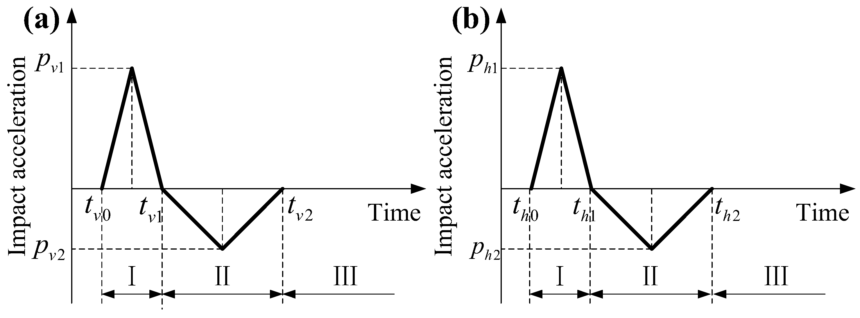
3.2.1. Simulation of Impact

An impact experiment was conducted firstly to measure the actual acceleration of huge impact. As shown in Figure 5, an impact testing machine consists of a pendulum hammer and a vertical hammer. The impact of pendulum hammer produces horizontal shocks and the impact of vertical hammer produces vertical shocks. The metal frame has the same dynamic properties ( m and I C ) as SINSs to simulate the SINS, which were verified using 3D modeling software, and is fixed on the mobile platform. Accelerometer on static platform of bumper can be fixed vertically or horizontally to measure the vertical and horizontal impacts, respectively. Finally, a portable data acquisition device for accelerometer gathers the data of accelerometer on static platform. Actual vertical and horizontal accelerations of huge impacts measured by accelerometer are plotted in Figure 6a and Figure 6b, respectively.
As shown in Figure 6a,b, the shape of actual impact is a curve consisting of two approximate triangle pulses, and each half triangle pulse of the curve has different amplitude and duration. According to BV043/85 criterion for shock analysis in the time domain, the experimental date of shock can be presented using an equivalent acceleration time–domain curve with a plus-minus half-sine acceleration wave [32]. The duration of each sine pulse is equal to the duration of each triangle pulse. The power of experimental results is assumed to be same as the power of simulation results. So, the amplitude of sine pulse is π / 4 times as the amplitude of triangle pulse, according to the power calculation of each pulse.
As illustrated in Figure 7, the amplitudes of first triangle pulses for vertical and horizontal impact are defined as p v 1 and p h 1 , respectively; the amplitudes of second triangle pulses for vertical and horizontal impact are defined as p v 2 and p h 2 , respectively; the intersections of vertical impact curve and time axis are defined as t v 0 , t v 1 and t v 2 , successively; and the intersections of horizontal impact curve and time axis are defined as t h 0 , t h 1 and t h 2 , successively. Each parameter can be obtained from Figure 6 and is listed in Table 3.
p v ( t ) = 0 , ( π / 4 ) · p v 1 sin ( 2 π / T v 1 ) · ( t t v 0 ) ] , ( π / 4 ) · p v 2 sin ( 2 π / T v 2 ) · ( t t v 1 ) ] , 0 , 0 t t v 0 t v 0 t t v 1 t v 1 t t v 2   , t t v 2 T v 1 = 2 ( t v 1 t v 0 ) , T v 2 = 2 ( t v 2 t v 1 )
p h ( t ) = 0 , 0 t t h 0 ( π / 4 ) · p h 1 sin ( 2 π / T h 1 ) · ( t t h 0 ) ] , t h 0 t t h 1 ( π / 4 ) · p h 2 sin ( 2 π / T h 2 ) · ( t t h 1 ) ] , t h 1 t t h 2   , 0 , t t h 2 T h 1 = 2 ( t h 1 t h 0 ) , T v 2 = 2 ( t h 2 t h 1 )
where p v ( t ) and p h ( t ) are simulation functions for vertical and horizontal impact, respectively. T v 1 and T v 2 are the durations of first and second sine curves for vertical impact simulation function. T h 1 and T h 2 are the durations of first and second sine curves for horizontal impact simulation function.

3.2.2. Impact Force

In order to analyze the impact-induced load response, stage when impact occurs and stage when impact finishes should be divided [33]. As shown in Figure 7, impact-induced load response is divided into three stages (Stage I, Stage II and Stage III).
Impact occurs in Stage I and Stage II. Impact stage is divided into two stages because the impact curve consists of two different triangle curves. In Stage I and Stage II, the mobile platform starts moving under impact and the bumper stores the impact energy. In Stage I and Stage II, non-displacement assumption is used: considering the instantaneity and significant amplitude of the impact as well as the inertia of load, it is assumed that mobile platform moves with acceleration same as the impact acceleration, but load is in non-displacement state. In Stage III, impact finishes and the free vibration of the load is decided by the displacement and the velocity at the end of Stage II.
According to the non-displacement hypothesis of the load during impact, the impact force can be derived. As shown in Figure 8, bumper with load is modeled as a spring-damping system using the definitions of stiffness, damping and mass matrices previously described. In static state, mobile platform and load are in their initial position. When impact occurs, mobile platform moves but load is still in its initial position. After impact, mobile platform stops motion immediately at the moment of the end of Stage II. So, in Stage I and II, using the dynamic model and movement of the mobile platform, the force on the load can be expressed as follows.
Q = K u + C u ˙ ,
where Q is the impact force on the load and u and u ˙ are displacement and velocity of the mobile platform in impact process, respectively.

3.3. Dynamic Equations of Bumper Under Impact

Lagrange’s equation was used to derive the dynamic equation of bumper under impact.
The general form of Lagrange’s equation is expressed as follows.
d d t T U q ˙ i T U q i + D q ˙ i = Q i i = 1 , 2 , , 6 ,
where T and U are the kinetic energy and potential energy of the system; D is dissipation function of the system; q i and q ˙ i are generalized displacement and generalized velocity of the load in corresponding generalized coordinates, respectively; and Q i is the generalized external forces on the load.
Before establishing dynamic equations of bumper under huge impact, two extra simplifications were listed: (1) the kinetic energy of buffer bars was ignored as mass of buffer bars was small relative to load and (2) gravitation of load was ignored because gravitation of load was negligible compared with the huge impact.
The kinetic energy of the load is expressed as follows.
T = 1 2 ω T I O ω + 1 2 m p ˙ T p ˙ .
The potential energy of the buffer bars is written as follows.
U = 1 2 Δ q T K Δ q .
The dissipation function of the buffer bars can be obtained as follows.
D = 1 2 q ˙ T C q ˙ .
Then, Equation (24) can be written as follows.
M q ¨ + C q ˙ + K q = Q .
Q is different in impact process and Stage III, so dynamic equations should be set up for impact process and Stage III separately.

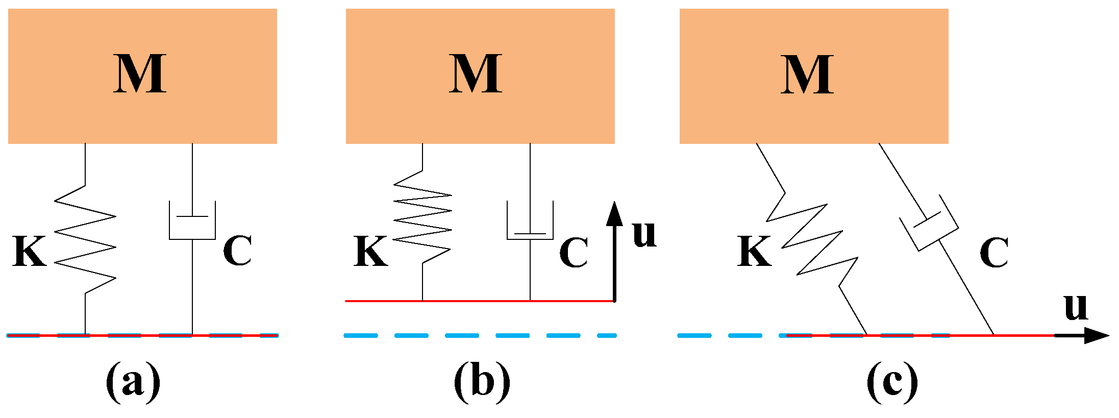
3.3.1. Dynamic Equations in Stage I and Stage II

In Stage I and Stage II, Equation (28) is expressed as follows.
M q ¨ + C q ˙ + K q = K u + C u ˙ .
An intermediate variable is introduced as follows.
q u = q u .
Then, Equation (29) is rewritten as follows.
M q ¨ u + C q ˙ u + K q u = M u ¨ .

3.3.2. Dynamic Equations in Stage III

In Stage III, the load is in a state of free vibration and Q = 0 , so the dynamic equation in Stage III is expressed as follows.
M q ¨ + C q ˙ + K q = 0 .
where 0 is a 6 × 6 null matrix.

4. Shock Isolation Performance

4.1. Evaluation of Shock Isolation Performance

In this paper, shock acceleration ratio (SAR) is selected as evaluation method for shock isolation performance of bumper because the acceleration in the load related to the ground frame is concerned in practice. So, the evaluation index of the bumper is defined as follows.
S A R = u ¨ max p ¨ max ,
where u ¨ max is the peak acceleration magnitude of the load in impact direction and p ¨ max is the peak acceleration magnitude of the impact in impact direction.

4.2. Theoretical Results

Runge–Kutta method was used to solve the dynamic equations. The solution procedure was divided into three stages, same as the three-stage partition of impact force on the load.
In Stage I, initial conditions are as follows:
q ¨ u s 1 : 0 = 0 q ˙ u s 1 : 0 = 0 q u s 1 : 0 = 0 .
In Stage II, initial conditions are as follows:
q ¨ u s 2 : 0 = q ¨ u s 1 : t 1 q ˙ u s 2 : 0 = q ˙ u s 1 : t 1 q u s 2 : 0 = q u s 1 : t 1 .
x-, y- and z-direction-impact accelerations are defined as u ¨ x , u ¨ y and u ¨ z , respectively, and each can be expressed as follows.
u ¨ x = p h t 0 0 0 0 0 T u ¨ y = 0 p h t 0 0 0 0 T u ¨ z = 0 0 p v t 0 0 0 T .
And acceleration of the load in Stage I and Stage II can be obtained using the following equation:
q ¨ = q ¨ u + u ¨ .
In Stage III, initial conditions are as follows:
q ¨ s 3 : 0 = q ¨ u s 2 : t 2 + u ¨ s 2 : t 2 q ˙ s 3 : 0 = q ˙ u s 2 : t 2 + u ˙ s 2 : t 2 q s 2 : 0 = q u s 2 : t 2 + u s 2 : t 2 .
Based on the solving method, the theoretical time domain responses of the load were obtained and are plotted in Figure 9, Figure 10 and Figure 11, and theoretical SARs of the bumper are listed in Table 4.

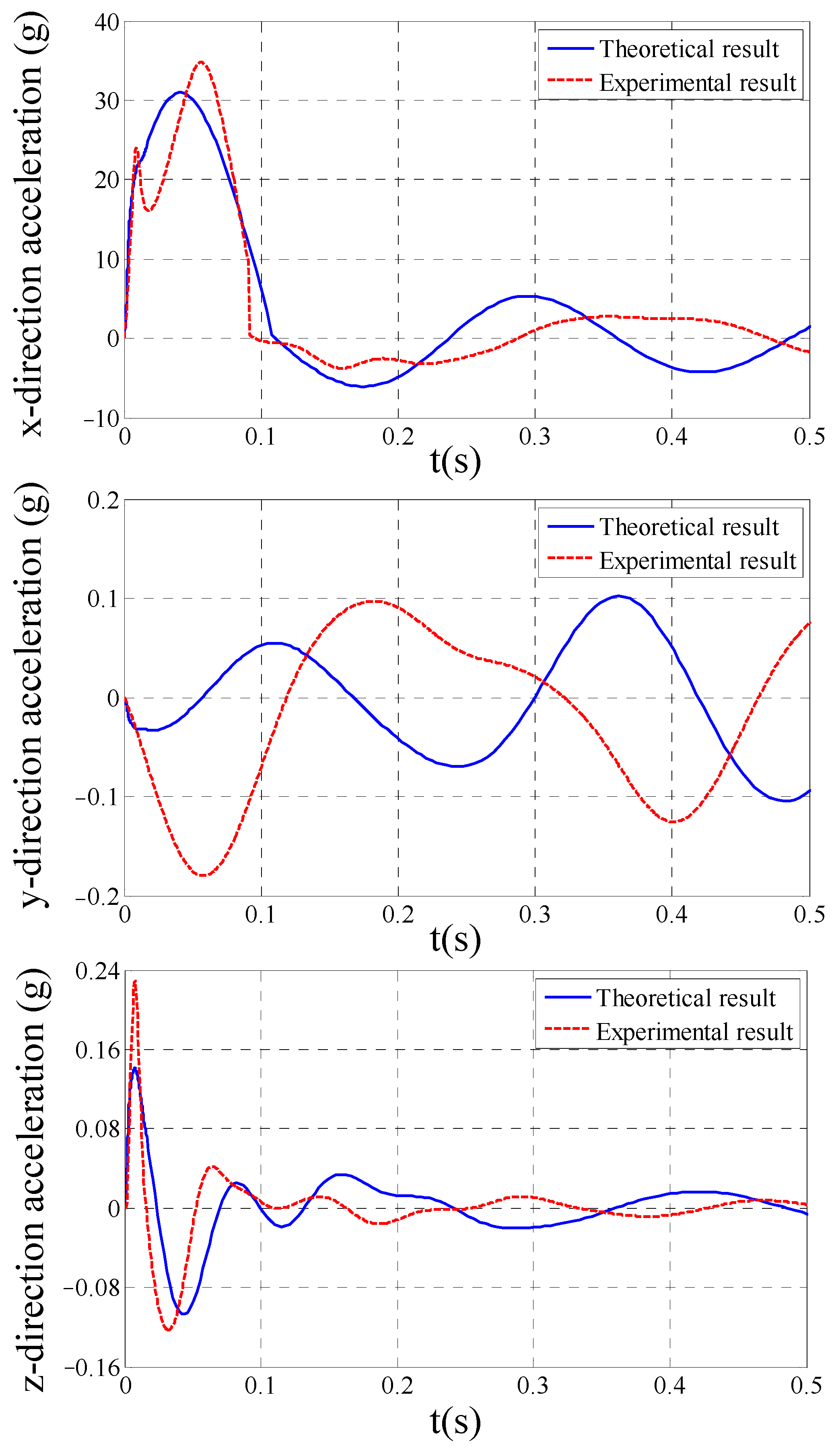
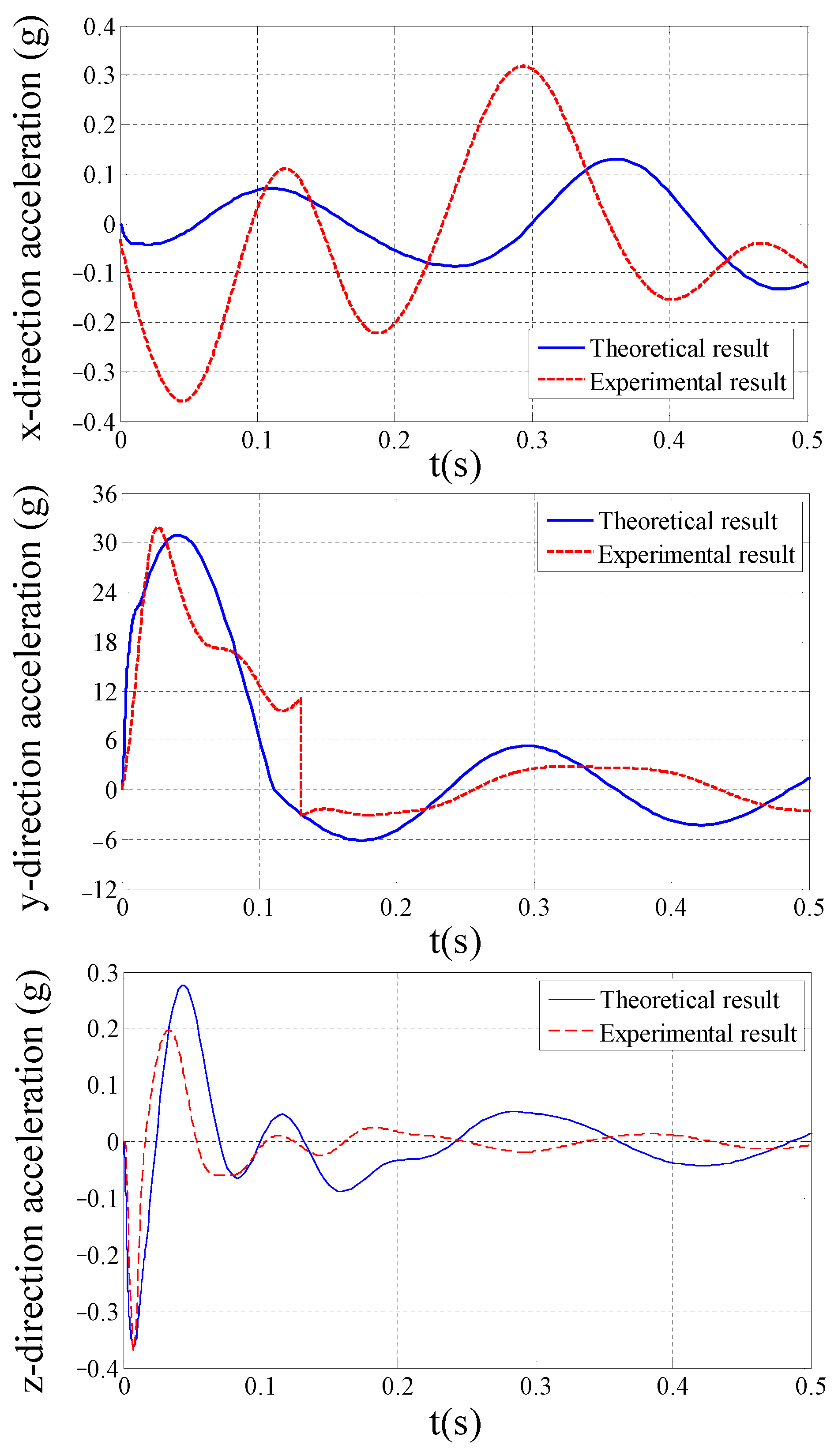
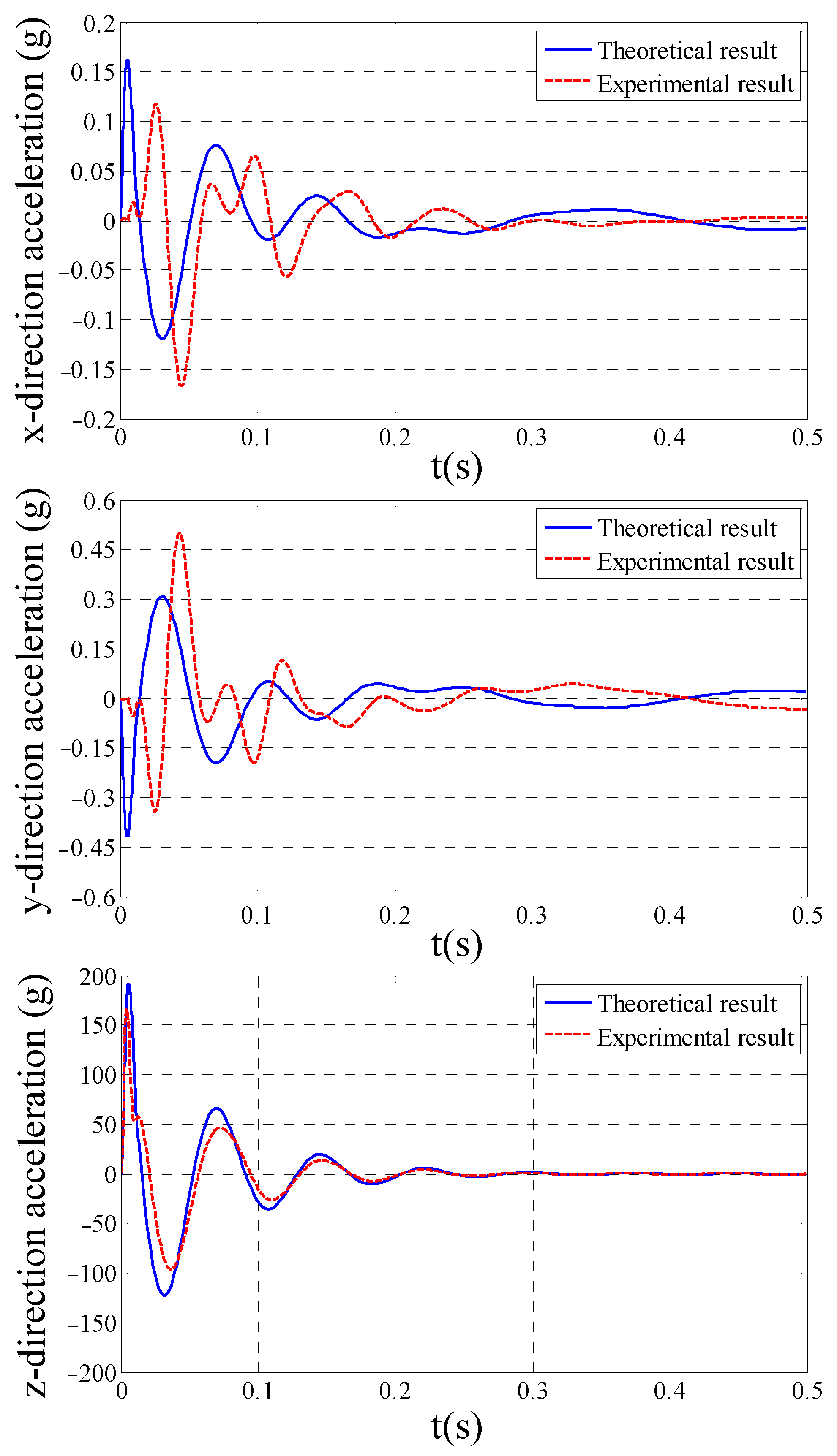
4.3. Experiment Results and Discussions

In order to prove the validity of the proposed method, an impact experiment was conducted to measure the actual acceleration of huge impact and the responding acceleration of the load. As shown in Figure 5, an impact testing machine consists of a pendulum hammer and a vertical hammer. The impact of pendulum hammer produces horizontal shocks, and the impact of vertical hammer produces vertical shocks. The metal frame has the same dynamic properties as SINSs to simulate the SINS and is fixed on the mobile platform. Accelerometer on static platform of the bumper can be fixed vertically or horizontally to measure the vertical and horizontal impacts, respectively. Accelerometer on static platform of the bumper can be fixed in the same direction as the accelerometer on mobile platform. Finally, a portable data acquisition device for accelerometer gathers the data of accelerometer on static platform.
The measured impact accelerations are illustrated in Figure 6, and the measured accelerations of the load are shown in Figure 9, Figure 10 and Figure 11. Moreover, experimental SARs of the bumper are listed in Table 4. A comparative validation study demonstrates strong concordance between simulated isolation performance metrics and experimental measurements, with theoretical predictions deviating less than 1.28% from empirical data, thereby confirming the computational model’s predictive fidelity. The difference between experimental and simulation results mainly comes from errors in impact simulation, measurement errors in testing instruments and the inability to fully replicate the output of impact experiments.

5. Conclusions

This article proposed a dynamic modeling and shock isolation performance analysis method for a Stewart-platform-based SINS’s bumper. The main findings are concluded as follows.
(1)
The theoretical x-, y- and z-direction-impact SARs are 1.96%, 1.96% and 9.51%, respectively;
(2)
The experimental x-, y- and z-direction-impact SARs are 2.21%, 2.21% and 8.23%, respectively;
(3)
The theoretical time domain responses of the load agree with the experiment results, with the theoretical predictions deviating less than 1.28% from the empirical data, verifying the proposed method.
In conclusion, the proposed method of dynamic modeling and shock isolation analysis for the Stewart-platform-based SINS’s bumper is practical and effective.

Author Contributions

Conceptualization, Y.T. and W.W.; methodology, Y.T.; software, H.Z.; validation, Y.L., W.W. and G.L.; formal analysis, H.L.; investigation, X.C.; resources, Y.H.; data curation, J.F.; writing—original draft preparation, Y.T.; writing—review and editing, W.W.; visualization, Y.H.; supervision, Y.T.; project administration, W.W.; funding acquisition, W.W. All authors have read and agreed to the published version of the manuscript.

Funding

This research was funded by the Jimei University Research Start-Up Fund (ZQ2022041 and ZQ2024016); the Fujian Provincial Natural Science Youth Fund (grant numbers: 2024J08195 and 2022J05155); the Fujian Provincial Natural Science General Fund (grant number: 2023J01791); the Xiamen Science and Technology Bureau Nature Fund (grant numbers: 3502Z202471046 and 3502Z20227057); the Fujian Province Young and Middle-Aged Teacher Education Research Project (Science and Technology) Key Project (grant number: JZ230027); and the Fujian Province Young and Middle-Aged Teacher Education Research Project (Science and Technology) General Project (grant number: JAT210236).

Data Availability Statement

The original contributions presented in the study are included in the article. Further inquiries can be directed at the corresponding author.

Conflicts of Interest

The authors declare no conflicts of interest.

Abbreviations

The following abbreviations are used in this manuscript:
SINSStrap-down inertial navigation system
DOFDegree-of-freedom
GPSGlobal positioning system
h Height of the bumper
R b Radius of the static platform
R a Radius of the mobile platform
β s Half-flare angle of the adjoining spherical hinge on the static platform
α m Half-flare angle of the adjoining spherical hinge on the mobile platform
O Center of mass of the static platform
O X Y Z Static platform frame
C Center of mass of the load (SINS and mobile platform)
C x y z Load frame
C X i Y i Z i Intermediate frame of the load
O g X g Y g Z g Ground frame
p = x p y p z p T Position vector of C in  O X Y Z
A i Upper spherical hinge centers
a i Coordinates   of   A i   in   C x y z
B i Lower spherical hinge centers
b i Coordinates   of   B i   in   O X Y Z
S i Vectors   of   buffer   bars   in   O X Y Z
Φ = α β γ T Euler   angles   of   the   mobile   platform   related   to   C X i Y i Z i
q Generalized coordinate of the mobile platform
R Rotation matrix of the platform
ω Rotation angular velocity vector of the mobile platform
s i Unit   vectors   of   the   buffer   bars   in   O X Y Z
l i Length scalars of the buffer bars
k Stiffness of the buffer bar
c Damping of the buffer bar
m Mass of the load
g Gravitational acceleration
I C Inertial tensor with respect to point C in  frame   C x y z
p v ( t ) Simulation function for vertical impact
p h ( t ) Simulation function for horizontal impact

References

  1. Liu, Y.; Sun, Y.; Li, B.; Wang, X.; Yang, L. Experimental Analysis of Deep-Sea AUV Based on Multi-Sensor Integrated Navigation and Positioning. Remote Sens. 2024, 16, 199. [Google Scholar] [CrossRef]
  2. Tang, J.; Bian, H. Ship SINS/CNS Integrated Navigation Aided by LSTM Attitude Forecast. J. Mar. Sci. Eng. 2024, 12, 387. [Google Scholar] [CrossRef]
  3. Wang, Y.; Jiao, R.; Wei, T.; Guo, Z.; Ben, Y. A Method for Predicting Inertial Navigation System Positioning Errors Using a Back Propagation Neural Network Based on a Particle Swarm Optimization Algorithm. Sensors 2024, 24, 3722. [Google Scholar] [CrossRef] [PubMed]
  4. Guo, J.; Huang, S.; Nikolay, T.; Li, M. Vibration damping of naval ships based on ship shock trials. Appl. Acoust. 2018, 133, 52–57. [Google Scholar] [CrossRef]
  5. Li, Y.; He, L.; Shuai, C.-g.; Wang, C.-y. Improved hybrid isolator with maglev actuator integrated in air spring for active-passive isolation of ship machinery vibration. J. Sound Vib. 2017, 407, 226–239. [Google Scholar] [CrossRef]
  6. Tao, Y.; Rui, X.; Yang, F.; Hao, B. Development of a MRE isolation system for strapdown inertial measurement unit. Mech. Syst. Signal Process. 2019, 117, 553–568. [Google Scholar] [CrossRef]
  7. Chen, W.; Wang, S.; Li, J.; Lin, C.; Yang, Y.; Ren, A.; Li, W.; Zhao, X.; Zhang, W.; Guo, W.; et al. An ADRC-based triple-loop control strategy of ship-mounted Stewart platform for six-DOF wave compensation. Mech. Mach. Theory 2023, 184, 105289. [Google Scholar] [CrossRef]
  8. Chen, N.; Huang, D.; Tu, Y.; Wei, D.; Lin, X. A novel inertial parameter identification method for the ship-mounted Stewart platform based on a wave compensation platform. Measurement 2025, 242, 116010. [Google Scholar] [CrossRef]
  9. Li, Z.; Du, H.; Si, J.; Wang, Z.; Xiong, W. Rigid-flexible coupling dynamic modeling and validation of a helicopter rescue simulator based on an inverted Stewart platform. Ocean Eng. 2025, 319, 120164. [Google Scholar] [CrossRef]
  10. Marneffe, B.D.; Avraam, M.; Deraemaeker, A.; Horodinca, M.; Preumont, A. Vibration Isolation of Precision Payloads: A Six-Axis Electromagnetic Relaxation Isolator. J. Guid. Control Dyn. 2009, 32, 395–401. [Google Scholar] [CrossRef]
  11. Luo, Q.; Li, D.; Jiang, J. Coupled dynamic analysis of a single gimbal control moment gyro cluster integrated with an isolation system. J. Sound Vib. 2014, 333, 345–363. [Google Scholar] [CrossRef]
  12. Wu, Y.; Yu, K.; Jiao, J.; Cao, D.; Chi, W.; Tang, J. Dynamic isotropy design and analysis of a six-DOF active micro-vibration isolation manipulator on satellites. Robot. Comput.-Integr. Manuf. 2018, 49, 408–425. [Google Scholar] [CrossRef]
  13. Yang, X.; Wu, H.; Chen, B.; Kang, S.; Cheng, S. Dynamic modeling and decoupled control of a flexible Stewart platform for vibration isolation. J. Sound Vib. 2019, 439, 398–412. [Google Scholar] [CrossRef]
  14. Tu, Y.; Yang, G.; Cai, Q.; Wang, L.; Zhou, X. Optimal design of SINS’s Stewart platform bumper for restoration accuracy based on genetic algorithm. Mech. Mach. Theory 2018, 124, 42–54. [Google Scholar] [CrossRef]
  15. Yang, J.; Xu, Z.; Wu, Q.; Zhu, M.; He, S.; Qin, C. Dynamic modeling and control of a 6-DOF micro-vibration simulator. Mech. Mach. Theory 2016, 104, 350–369. [Google Scholar] [CrossRef]
  16. Chen, G.; Yu, W.; Li, Q.; Wang, H. Dynamic modeling and performance analysis of the 3-PRRU 1T2R parallel manipulator without parasitic motion. Nonlinear Dyn. 2017, 90, 339–353. [Google Scholar] [CrossRef]
  17. Chen, G.; Rui, X.; Abbas, L.K.; Wang, G.; Yang, F.; Zhu, W. A novel method for the dynamic modeling of Stewart parallel mechanism. Mech. Mach. Theory 2018, 126, 397–412. [Google Scholar] [CrossRef]
  18. Bernal, J.; Campa, R.; Soto, I. Kinematics and dynamics modeling of the 6-3-PUS-type Hexapod parallel mechanism. J. Mech. Sci. Technol. 2018, 32, 4555–4570. [Google Scholar] [CrossRef]
  19. Shao, P.; Wang, Z.; Yang, S.; Liu, Z. Dynamic modeling of a two-DoF rotational parallel robot with changeable rotational axes. Mech. Mach. Theory 2019, 131, 318–335. [Google Scholar] [CrossRef]
  20. Luo, G.W.; Lv, X.H.; Zhu, X.F.; Shi, Y.Q.; Du, S.S. Diversity and transition characteristics of sticking and non-sticking periodic impact motions of periodically forced impact systems with large dissipation. Nonlinear Dyn. 2018, 94, 1047–1079. [Google Scholar] [CrossRef]
  21. Shen, Y.; Xiang, D.; Wang, X.; Jiang, L.; Wei, Y. A contact force model considering constant external forces for impact analysis in multibody dynamics. Multibody Syst. Dyn. 2018, 44, 397–419. [Google Scholar] [CrossRef]
  22. Shu, D.-W.; Shi, B.-J.; Meng, H.; Yap, F.F.; Jiang, D.-Z.; Ng, Q.; Zambri, R.; Lau, J.H.T.; Cheng, C.-S. Shock analysis of a head actuator assembly subjected to half-sine acceleration pulses. Int. J. Impact Eng. 2007, 34, 253–263. [Google Scholar] [CrossRef]
  23. Harmoko, H.; Yap, F.F.; Vahdati, N.; Li, C. Design and Analysis of Shock and Random Vibration Isolation of Operating Hard Disk Drive in Harsh Environment. Shock Vib. 2009, 16, 143–154. [Google Scholar] [CrossRef]
  24. Wang, X.; Yang, B.; Yu, H.; Gao, Y. Transient vibration analytical modeling and suppressing for vibration absorber system under impulse excitation. J. Sound Vib. 2017, 394, 90–108. [Google Scholar] [CrossRef]
  25. Yan, L.; Xuan, S.; Gong, X. Shock isolation performance of a geometric anti-spring isolator. J. Sound Vib. 2018, 413, 120–143. [Google Scholar] [CrossRef]
  26. He, Q.; Zeng, C.; Gao, Z.; Wu, Z. Analysis and Design of the Stewart Platform-Based Parallel Support Bumper for Inertially Stabilized Platforms. IEEE Trans. Ind. Electron. 2020, 67, 4203–4215. [Google Scholar] [CrossRef]
  27. Wu, P.; Xiong, H.; Kong, J. Dynamic analysis of 6-SPS parallel mechanism. Int. J. Mech. Mater. Des. 2012, 8, 121–128. [Google Scholar] [CrossRef]
  28. Wohlhart, K. Mobile 6-SPS Parallel Manipulators. J. Robot. Syst. 2003, 20, 509–516. [Google Scholar] [CrossRef]
  29. Hassan, A.; Abomoharam, M. Modeling and design optimization of a robot gripper mechanism. Robot. Comput.-Integr. Manuf. 2017, 46, 94–103. [Google Scholar] [CrossRef]
  30. Gosselin, C.; Schreiber, L. Kinematically Redundant Spatial Parallel Mechanisms for Singularity Avoidance and Large Orientational Workspace. IEEE Trans. Robot. 2016, 32, 286–300. [Google Scholar] [CrossRef]
  31. Jiang, H.-Z.; He, J.-F.; Tong, Z.-Z. Characteristics analysis of joint space inverse mass matrix for the optimal design of a 6-DOF parallel manipulator. Mech. Mach. Theory 2010, 45, 722–739. [Google Scholar] [CrossRef]
  32. Su, Y.; Gu, Y.; Keogh, P.S.; Yu, S.; Ren, G. Nonlinear dynamic simulation and parametric analysis of a rotor-AMB-TDB system experiencing strong base shock excitations. Mech. Mach. Theory 2021, 155, 104071. [Google Scholar] [CrossRef]
  33. Wang, X.; Yang, B. Transient vibration control using nonlinear convergence active vibration absorber for impulse excitation. Mech. Syst. Signal Process. 2019, 117, 425–436. [Google Scholar] [CrossRef]
Figure 1. Schematic diagram of the Stewart-platform-based 6-DOF vibration isolation system for shipborne SINSs.
Jmse 13 01007 g001
Figure 2. Structure of buffer bar.
Jmse 13 01007 g002
Figure 3. Mechanical configuration of the bumper.
Jmse 13 01007 g003
Figure 4. Kinematic reference frames and lumped parameter model of marine SINS isolation platform.
Jmse 13 01007 g004
Figure 5. Impact experiment for Stewart-platform-based bumper: (a) panoramic view of the test and (b) accelerometers’ locations.
Jmse 13 01007 g005
Figure 6. Experimental and simulation results of impact: (a) vertical impact and (b) horizontal impact.
Jmse 13 01007 g006
Figure 7. Parameter definition of the measured impact curves: (a) vertical impact and (b) horizontal impact.
Jmse 13 01007 g007
Figure 8. Impact force on load: (a) static state, (b) vertical impact stage and (c) horizontal impact stage.
Jmse 13 01007 g008
Figure 9. Theoretical and experimental accelerations of the load due to x-direction impact.
Jmse 13 01007 g009
Figure 10. Theoretical and experimental accelerations of the load due to y-direction impact.
Jmse 13 01007 g010
Figure 11. Theoretical and experimental accelerations of the load due to z-direction impact.
Jmse 13 01007 g011
Table 1. Structural parameters of the bumper.
h /mm R b /mm R a /mm β s α m
174.02250.00250.0014.5814.58
Table 2. Dynamic parameters of the bumper.
Dynamic ParametersValues
p = x p y p z p T 0.308 0.794 299.404  mm
k 44,000 N/m
c 200 N·s/m
m 30.78 kg
I C 0.2612 0.0002 0.0011 0.0002 0.3210 0.0028 0.0011 0.0028 0.2554  kg·m2
Table 3. Parameters of vertical and horizontal impact curves.
p v 1 /g p v 2 /g t v 0 /ms t v 1 /ms t v 2 /ms
2015−11191513
p h 1 /g p h 2 /g t h 0 /ms t h 1 /ms t h 2 /ms
1573−3441516
Table 4. Theoretical and experimental SARs of the bumper.
Impact
Direction
Theoretical ResultsExperimental Results
u ¨ max /g p ¨ max /g S A R u ¨ max /g p ¨ max /g S A R
x-direction30.8515731.96%34.7815732.21%
y-direction30.9015731.96%31.8415732.21%
z-direction191.720159.51%166.020158.23%
Disclaimer/Publisher’s Note: The statements, opinions and data contained in all publications are solely those of the individual author(s) and contributor(s) and not of MDPI and/or the editor(s). MDPI and/or the editor(s) disclaim responsibility for any injury to people or property resulting from any ideas, methods, instructions or products referred to in the content.

