Abstract
This paper introduces a novel approach to modeling and control system design for tugboat-assisted operations, such as the docking and rescue of marine vessels. In these scenarios, one or more tugboats push, pull, or guide large vessels to ensure precise and safe maneuvering. Their control systems ensure accurate coordination, vessel positioning, and overall stability, even in the presence of system uncertainties, imperfect control allocation, and ocean disturbances. To address these challenges, a mathematical model of a general tugboat-assisted system is first derived. Then, a new vector of variables is introduced, leading to a modified model representation where the mismatches from the allocation and lower-level tugboat controllers can be realized in the vessel’s motion equation. Thus, the design of a controller can take this aspect into account to enhance the overall system’s performance and stability. Thirdly, a control system design method is proposed, employing a centralized control framework and ensuring a mixed performance criterion. Finally, a case study is conducted with a particular tugboat-assisted configuration and the results validate the effectiveness of the control solution.
1. Introduction
In the first quarter of the 21st century, the global Gross Domestic Product (GDP) has tripled since the early 2000s, with maritime transportation handling 80% of international trade volume and 50% of its value [1,2]. To keep up with the massive expansion of the global economy, the demand for increasingly efficient maritime transportation has intensified. However, those vessels will easily suffer from the difficulty of navigation and maneuverability, which may lead to serious consequences. For instance, the 2021 Suez Canal obstruction by poor maneuverability of the Ever Given vessel disrupted a humongous USD 10 billion worth of goods and a loss of USD 14 million per day for the Egyptian government [3,4]. Hence, there is a need for advanced technology to position and maneuver marine vessels in various situations such as docking and undocking large ships or maneuvering offshore platforms through narrow passages, such as shown in Figure 1.
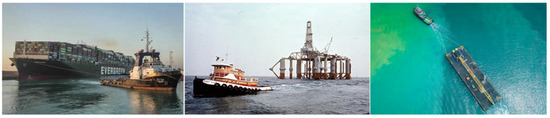
Figure 1.
Tugboat-assisted operations in maritime transportation.
To enhance the maneuverability of marine vessels, tugboats play a crucial role in providing pushing and pulling assisting forces [5]. Proper coordination of multiple tugboats simplifies complex operations, improves safety, and has become increasingly important with the growing demand for offshore energy development and expanding maritime trade. Traditionally, the operation of tugboats depends on manual control, requiring skilled pilots to precisely manage the pull/push force, heading angle, or direction [6]. Hence, coordinating multiple tugboats in complex maneuvers demands harmonious communication among operators, which is labor-intensive and poses inherent risks. However, recent improvements in autonomous tugboat technology have accelerated commercial interest [5,7,8]. This shift paves the way for fully automated offshore platform transportation, offering an improvement in efficiency, safety, and minimizing human involvement.
Nevertheless, the tugboat configurations, system uncertainties, environmental disturbances, and especially control strategies still require continuous evaluation and enhancement. For instance, existing studies often focus on specific systems with a predetermined number of tugboats and configuration, leading to case-specific models and control designs that limit operational flexibility. In this study, we introduce a new approach to modeling and control system design for tugboat-assisted operations, such as docking and rescuing marine vessels. The mathematical model of a general tugboat-assisted system is first derived and then modified with a new variable vector that is beneficial for subsequent control system design. Then, a centralized control system is designed, employing the state feedback synthesis to solve the mixed control performance problem. A case study is conducted to validate the control solution.
The contributions of this paper can be summarized as follows:
- A mathematical model of a general tugboat-assisted system, applicable to any specific tugboat-assisted configuration.
- A modified model incorporating new variable vectors that linearly couple the dynamics of the transported vessel and tugboats and thus benefit for the control system design process.
- A centralized control scheme and control law design method for tugboat-assisted systems, based on mixed control performance, utilizing state feedback, and linear matrix inequality techniques.
- Case studies validating the proposed control solution.
2. Related Studies
To develop an effective tugboat-assisted system, the tugboat configuration, and subsequently, the dynamics of the entire system need to be investigated. In [9], a single tugboat configuration with the strategy of leader–follower is proposed and investigated. Another platform introduced in [10,11,12] allows the passive vessel without rudders to be assisted by two tugboats; one in the front and the other in the back. In [13,14], two tugs are positioned ahead of the towed vessel. The study [15] offers a configuration of two tow-tug placed in the front and one pushing tug on the side, hence, eliminating the yawing moment of the passive vessel. However, even with these configurations, the system dynamics remain nonholonomic.
Consequently, four-tug arrangements are commonly employed in applications such as [16,17,18], while research [19,20,21] explores six-tug combinations, thereby enhancing maneuverability in complex operating conditions. Nevertheless, this setup requires significant space, making it difficult to apply in narrowed or complex operational areas. Hence, the studies [22,23,24,25] position two pushing tugs and two towing tugs on one side of the platform to optimize space occupation. By balancing opposing push/pull forces, the system maintains maneuverability comparable to traditional configurations. Additionally, [12,13] derived a model for the tugboat cable force and analyzed its influence on the motion of the towing tug. Unfortunately, the variation in tugboat configurations requires specific control solutions for each case, making a universal solution highly desirable.
Additionally, uncertainties and disturbances must be considered when developing a tugboat-assisted control system. In [21], a sliding mode control is applied with the optimization of thrust forces and tug force directions, and the number of tugboats is arbitrary. The optimal-based allocation is again utilized in [20], in which the adaptive control and Lyapunov-based approach ensures the stability of the fixed 6-tug system. In [26], the model predictive control focuses on trajectory tracking and fuel consumption; and in [27], it is integrated with optimal-based and event-triggered mechanisms to ensure system stability and robustness. However, in these studies, the disturbances are usually omitted, and the tugboats are a maximum of two tugs. Consensus-based control [28] produced promising results, especially in low-speed maneuvering and positioning operations mostly without the interference of disturbances.
Mentioned above are decentralized control systems [17,18,19,20,21,26,27,28]. Although they have the benefits of flexibility, they integrate different control techniques that correspond to each vessel’s unique dynamics. However, they suffer from reliance on a cascade control structure, which primarily ensures input-to-state stability at best. In [22], an approach of centralized control, with the control allocation based on pseudo-inverse method, is proposed. Simulation results confirmed the effectiveness of the proposed system, but this allocation method can lead to unstable outputs, and the study’s system model limitations prevented the definition of references for the tugs, hindering the validation of the control approach’s feasibility. Reference [25] addressed these challenges by treating the allocation design as a constrained optimization problem and developing a robust control strategy. The results show the control allocation still affects significantly control performance.
3. System Modeling
The vessel being transported lacks both propulsion and actuators to regulate its movement, requiring external assistance for maneuvering. We consider a general configuration of (m + n) tugboats assisting the vessel’s motion (m, n ≥ 0). m tugboats provide towing forces to the vessel via towing lines connected to fixed connection points on the vessel. The n other tugboats push the vessel by their nose on the vessel’s hull. Figure 2 depicts an example system consisting of two towing tugboats and two other pushing boats and they are on one side of the transported vessel. The side is either at the front, for route-following tasks, or on the outer side, during berthing operations, of the vessel. The motions are described in the standard geographic reference frame and the body-fixed frames, as also elaborated in Figure 2. In particular, the origin of each body-fixed coordinate system is located at the geometric center of the corresponding marine vehicle.
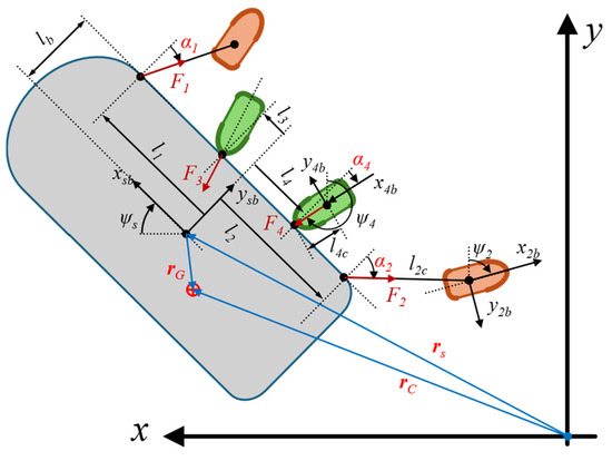
Figure 2.
A case study of tugboat-assisted docking system for a marine vessel.
The relative positions between the vessel and the tugboats are derived from the following:
- For the ith tugboat being a towing tugboat:
li: the longitudinal distance from the coordinate origin of the vessel-fixed frame to the connection point on the vessel of the towing line connected to the ith tugboat.
lib: the lateral distance from the coordinate origin of the vessel-fixed frame to the connection point on the vessel of the towing line connected to the ith tugboat.
lic: the length of the towing line, from the ith connection point connected to the ith tugboat, assuming that the end-connection point is at the coordinate origin of the tugboats.
αi: The relative angle between the towing force from the ith tugboat and the lateral axis of the vessel. It is equal to the relative angle between the towing line connected to the ith tugboat and the lateral axis of the vessel if the line is in tension.
- For the jth tugboat being a pushing tugboat:
lj: the longitudinal distance from the coordinate origin of the vessel-fixed frame to the point of application of impact force from the jth tugboat.
ljb: the lateral distance from the coordinate origin of the vessel-fixed frame to the point of application of impact force from the jth tugboat.
ljc: the longitudinal distance from the coordinate origin of the jth tugboat-fixed frame to its nose, i.e., the point of application of impact force from the tugboat.
αj: The relative angle between the pushing force from the jth tugboat and the vessel’s lateral axis. Generally, the pushing resultant consists of a normal force and a tangent friction force between the tugboat’s nose and the vessel’s hull. Without slippage between the two surfaces, the pushing force is in line with the longitudinal axis of the tugboat.
Furthermore, the assisting forces generated by the ith towing tugboat and the jth pushing tugboat are denoted by Fi and Fj, respectively. Additionally, vector depicts the deviation of the vessel’s mass center from its geometry center, which results in two corresponding position vectors and .
Then, the motion equations of the transported vessel are written as follows:
where is the vector of position and heading angle of the vessel in the reference frame, and contains the surge, sway, and yaw velocities. The kinematic relationship between frames is provided by the rotation matrix given by the following:
where and for simplification.
represents the vessel’s mass and inertia, is the Coriolis and centripetal matrix, and is the total damping matrix. Particularly, and , with the former elements parameterized from the vessel’s rigid body and the latter elements being the added mass due to the inertia of the surrounding water. They are written as follows:
In which, the rigid-body mass is ms, the moment of inertia about the vertical axis of the vessel-fixed frame is Iz, and the vessel’s center of gravity is at . The notation SNAME [29] is used for the remaining hydrodynamic added mass forces in the above matrices.
Finally, the vector of actuating forces and moment is , corresponding to the surge force, sway force, and yaw moment, respectively. In the case of the tugboat-assisting system, , with F being the vector of assisting forces from the tugboats and being the configuration matrix of these forces acting on the vessel. One can see that the elements of depend on the relative angles, represented by the relative angles vector , and the distance from the origin of the vessel-fixed frame to the connection points/points of applications, i.e., l. Finally, are those of environmental disturbances.
The dynamics of the ith towing tugboats (i = 1 ~ m) can be derived in a similar manner and result in the following:
Especially, the term is the reaction of the tugboat assisting force with the magnitude . Based on the geometrical relationship among the ships, is derived as follows:
For each ith towing tugboat, we consider being the connection point to the towing line and it is fixed in the vessel-fixed frame. Let be the distance between the point to the coordinate origin of the ith tugboat. means that the ith towing line is in tensioned, i.e., and vice versa, if , (the towing lines are considered as weightless). The geometry constraints between the points are as follows:
On the other hand, for the jth pushing tugboat in the system:
is the point of application of the jth pushing force. In this case, depends on the relative position of the vessel and the pushing tugboat. The vessel and the jth pushing tugboat are in contact if the distance between and , , meaning that . Thus, if , . Additionally, the model of interaction forces, i.e., towing forces and pushing forces between the vessel and the tugs, have been thoroughly derived, for example, in [30]. Therefore, they are adopted for this paper.
4. Control System Design
A conventional approach for controlling such a system starts with a supervisory control for the vessel motion, the distribution of the commands over the tugboats by a control allocation mechanism, and finally, control of the tugboats following the given commands. Hence, it often results in a hierarchical control scheme, where the best-case result is an input-to-state stable system, and the control allocation significantly affects control performance. Thus, we introduce a centralized control approach, in such that the control of the vessel control and the control of the tugboats are derived simultaneously. The two control system design approaches are illustrated in Figure 3.
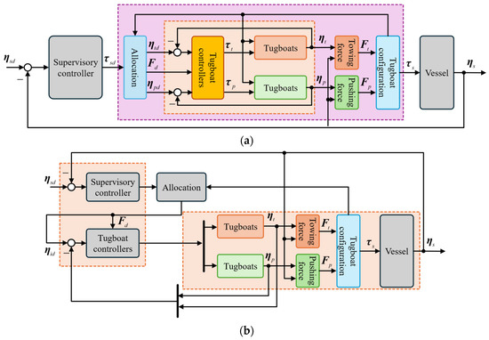
Figure 3.
Tugboat-assisted control schemes; schematic drawn by the authors. (a) A hierarchical control such as cascade control. (b) The proposed centralized control.
4.1. Transformed System Model
Hence, to derive a new control solution, we start by rewriting the model of the vessel (Equation (1)) as follows:
with
and the ith tugboat, either the towing (Equation (4)) or pushing (Equation (7)) one, as follows:
Then, taking the time derivative of the geometrical constraints in Equations (6) and (7) results in the relative kinematics as follows:
- If the ith tugboat is a towing tugboat,
Denote and rewrite Equation (10) as follows:
In Equation (11), Ik represents the identity matrix size k.
- If the ith tugboat is a pushing tugboat, the longitudinal distance li is not a constant value, i.e., , and the pushing force is in line with the longitudinal axis of the tugboat, i.e., or . Therefore,
By defining , Equation (12) is then rewritten as follows:
Additionally, the Taylor series expansions of the vessel control input to the first order is obtained in the following form:
in which the center given by , and are the desired values regarding the distances l, the relative angles α, and the assisting forces F. , , and are the corresponding first partial derivatives. It is also worth noting that regarding the distances l, only the longitudinal distances from the vessel-fixed frame origin to the impact points of the pushing tugboats are changed. Finally, s is the remainder.
Now, considering the newly defined in Equations (11) and (13), Equation (14) can be rewritten as follows:
with Op´q being the p-by-q null matrix (and Op being the p-by-p square null matrix).
From Equations (1), (4), (11), (13) and (15), we obtain the model of the entire system as follows:
with and .
One of the benefits of the newly obtained model is that the mismatches due to the allocation and lower-level tugboat controllers appear in the motion equation of the vessel. Thus, the design of a supervisory controller for the vessel can take this aspect into account to enhance the overall system’s performance and stability. From model (16), the vessel controller and the tugboat’s controller can also be designed simultaneously, regardless of the allocating procedure. This approach is introduced in the next section.
4.2. State-Feedback Synthesis for the Tugboat-Assisted Transportation Systems
Let us choose the vector of state variables for the tugboat-assist dynamic positioning systems as follows:
and the control inputs vector and disturbances vector are chosen by the following:
The linearization of the nonlinear model (16) with respect to the chosen states and inputs, and with the output being , gives the following:
where the system matrices are derived, lengthy but straightforward, as follows:
where the tilde above each matrix denotes the linearized matrix obtained from that matrix.
Additionally, given the desired trajectory of the vessel, define the trajectory tracking error as and its integral . An updated state-space realization is obtained, including the output equations reflecting the control objectives for such problems of vessel transportation:
with
The control objective, expressed in the form of a mixed problem, is to minimize the influence of disturbances and varying reference on the system output (in the form of the random-mean-squares (RMS gain) and the H2 norm of the transfer function from to . For this, assume that is controllable; a state feedback control is proposed as follows.
It is noted that by control law (24), the supervisory control input for the vessel, , and the tugboats’ control are computed simultaneously. The design objective can be formulated by linear matrix inequalities, such as [31]. Thereby, an optimal trade-off between H2 and H∞ performances and the feedback matrix K can be obtained.
5. Case Studies
The proposed control strategy is validated with the tugboat configuration given in Figure 2. The case study consists of two tugboats towing an oil tanker via towing lines while two others push it in the opposite direction. All tugboats are positioned on the outer side of the tanker, towing tugs are outside and two pushing tugs are inside, and perform a docking operation. This arrangement allows for sufficient maneuverability by adjusting the amplitude and angle of impact of the towing and pushing forces. The safe and effective movement of the tanker is achieved through the control of the corresponding tugboats. From Figure 2, one can write the configuration matrix of the tugboats, and subsequently, the actuating forces and moment acting on the assisted tanker, as follows:
The specifications of the tanker are adopted from the well-known ESSO 190000 dwt tanker from [32]. The tugboats are referred to in [30] and [33], which are based on a realistic tugboat model with an Azimuthal Stern Drive (Z-Drive) propulsion system. These references present full-scale and model-scale tugboats whose hydrodynamic behavior and interaction characteristics have been extensively validated through numerical and experimental studies. The primary parameters adopted in our simulation are summarized in Table 1.

Table 1.
Parameters of the tanker and tugboats.
The detailed hydrodynamic derivatives are listed in [30,32,33]. The model of the entire system is obtained following the procedure introduced in previous sections. Additionally, to take into account the model uncertainties and environmental disturbances, we consider that the center of the gravity of the tanker does not coincide with its coordinate origin. Hence, xG and yG are the uncertain parameters in the tanker’s mass and inertia matrix.
The optimal state-feedback is obtained for this uncertain system by minimizing , where is the RMS gain of the transfer function from to given in Equation (22), and is the H2 norm of the transfer function from to . is chosen for the trade-off between the two criteria. The linear matrix inequality technique is used for the state-feedback synthesis problem with uncertainties.
A docking scenario is considered. The tanker moves from its original position (initial surge, sway, and yaw positions are zero) to follow the desired docking trajectory within 1200 [s]. The responses of the assisted tanker are presented in Figure 4, Figure 5, Figure 6, Figure 7 and Figure 8. In particular, Figure 4 shows the two-dimensional horizontal motions of the vessel. The controlled translational position and yaw angle responses are indicated in Figure 5, while its rate of change is depicted in Figure 6. In addition, the tracking errors are illustrated in Figure 7. Finally, Figure 8 shows the control effort acting on the head to guide the vessel following the desired reference.
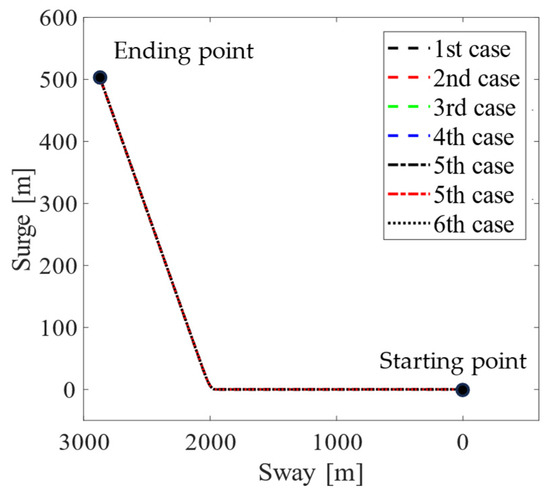
Figure 4.
Trajectory tracking of the vessel’s translational positions.

Figure 5.
Motion control system responses of the tugboat-assisted vessel.
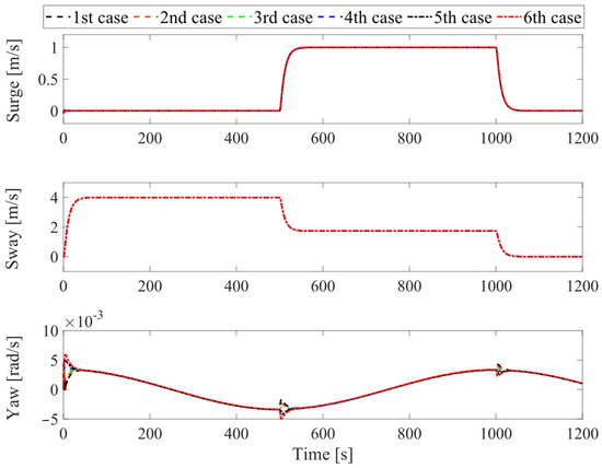
Figure 6.
Translational and rotational velocities of the assisted vessel.
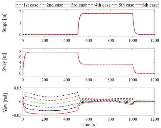
Figure 7.
Trajectory tracking errors of the vessel.
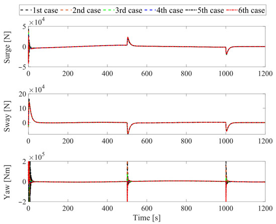
Figure 8.
Vessel’s control efforts.
Moreover, the black dotted line represents the desired reference in Figure 4 and Figure 5. The remaining lines of these figures follow the convention: the black dashed line, the red dashed line, the green dashed line, the blue dashed line, the black dashed-dotted line, and the red dashed-dotted line correspond to six pairs (xG, yG) values, increasing from the smallest value (, ) to the largest value (, ), and evenly distributed into six pairs. In the remaining figures, we refer to these six pairs in order, with the smallest value corresponding to first case, and the largest value corresponding to sixth case.
In summary, as observed from the motion control responses in Figure 4 and Figure 5, the proposed control system demonstrates good stability and tracking performance, even in the presence of the tanker’s uncertainties. Particularly, in Figure 7, at the stage around the 500th [s] and 1000th [s], the tracking error of the controlled yaw angle has a tendency to deviate from the desired tracking route, as the results from the change in x-, y-directions of the vessel during the tracking period. However, the tracking errors of all vessel’s motions always remain overall at a very small value. In Figure 8, except for the departure stage, where the vessel requires sufficiently large forces and torques to transition from the steady state, the overall effort during operations remains consistently low. Hence, one can conclude that the proposed control system can achieve robust motion control performance, implying ensured fast and safe operation in further practical implementations.
6. Conclusions
This paper has introduced a novel approach to modeling and control system design for tugboat-assisted operations, such as docking and rescuing marine vessels. Mathematical models for a general tugboat-assisted system are developed and can be implemented for any tugboat configurations. The modeling utilizes a new variable vector that is beneficial for the later control system design, compared to the conventional dynamic models of marine vehicles. Thereby, a control system design method has been proposed, employing a state-feedback control and ensuring a mixed H₂/H∞ performance criteria. The case study has been performed with the tugboat-assisted transportation system for a marine vessel, where two tugboats push, and two other tugs pull the vessel from the same side. The simulation results validate the effectiveness of the control solution. For future work, the allocation design will be incorporated into this control system design problem. More study cases, including laboratory and real-world experiments, will be investigated to further validate and evaluate the proposed solutions.
Author Contributions
Conceptualization, T.H. and Y.-B.K.; methodology, T.H. and J.-S.P.; software, T.H. and C.-T.D.; validation, Y.-B.K., T.H. and J.-S.P.; formal analysis, T.H.; investigation, J.-S.P.; resources, Y.-B.K. and J.-S.P.; data curation, T.H. and T.-N.N.; writing—original draft preparation, T.H. and T.-N.N.; writing—review and editing, Y.-B.K., T.H. and J.-S.P.; visualization, T.H., T.-N.N. and C.-T.D.; supervision, Y.-B.K.; project administration, Y.-B.K.; funding acquisition, Y.-B.K. All authors have read and agreed to the published version of the manuscript.
Funding
This research was supported by the National Research Foundation of Korea (NRF) grant funded by the Korean government (MSIT) (No. 2022R1A2C1003486).
Data Availability Statement
The original contributions presented in the study are included in the article; further inquiries can be directed to the corresponding authors.
Conflicts of Interest
The authors declare no conflicts of interest. The funders had no role in the design of the study; in the collection, analyses, or interpretation of data; in the writing of the manuscript; or in the decision to publish the results.
References
- O’Neill, A. Global Gross Domestic Product (GDP) at Current Prices from 1985 to 2029 (in Billion U.S. Dollars). Available online: https://www.statista.com/statistics/268750/global-gross-domestic-product-gdp/ (accessed on 24 March 2025).
- Ferrari, E.; Christidis, P.; Bolsi, P. The Impact of Rising Maritime Transport Costs on International Trade: Estimation Using a Multi-Region General Equilibrium Model. Transp. Res. Interdiscip. Perspect. 2023, 22, 100985. [Google Scholar] [CrossRef]
- Wan, Z.; Su, Y.; Li, Z.; Zhang, X.; Zhang, Q.; Chen, J. Analysis of the Impact of Suez Canal Blockage on the Global Shipping Network. Ocean. Coast. Manag. 2023, 245, 106868. [Google Scholar] [CrossRef]
- Harun-Al-Rashid, A.; Yang, C.S.; Shin, D.W. Detection of Maritime Traffic Anomalies Using Satellite-AIS and Multisensory Satellite Imageries: Application to the 2021 Suez Canal Obstruction. J. Navig. 2022, 75, 1082–1099. [Google Scholar] [CrossRef]
- Choi, J.H.; Jang, J.Y.; Woo, J. A Review of Autonomous Tugboat Operations for Efficient and Safe Ship Berthing. J. Mar. Sci. Eng. 2023, 11, 1155. [Google Scholar] [CrossRef]
- Koznowski, W.; Łebkowski, A. Port Tugboat Formation Multi-Agent Control System. Int. J. Mar. Navig. Saf. Sea Transp. 2021, 15, 807–814. [Google Scholar] [CrossRef]
- Koznowski, W.; Łebkowski, A. Unmanned Electric Tugboat Formation Multi-Agent Energy-Aware Control System Concept. Energies 2022, 15, 9592. [Google Scholar] [CrossRef]
- Balakrishnan, P.K.; Sasi, S. Technological and Economic Advancement of Tug Boats. IOSR J. Mech. Civ. Eng. 2016, 87, 87–96. [Google Scholar]
- Lee, D.H.; Chakir, S.; Kim, Y.B.; Tran, D.Q. Control System Design for Vessel Towing System by Activating Rudders of the Towed Vessel. Int. J. Nav. Archit. Ocean Eng. 2020, 12, 943–956. [Google Scholar] [CrossRef]
- Du, Z.; Negenborn, R.R.; Reppa, V. Cooperative Multi-Agent Control for Autonomous Ship Towing under Environmental Disturbances. IEEE/CAA J. Autom. Sin. 2021, 8, 1365–1379. [Google Scholar] [CrossRef]
- Du, Z.; Negenborn, R.R.; Reppa, V. Multi-Vessel Cooperative Speed Regulation for Ship Manipulation in Towing Scenarios. IFAC-Pap. 2021, 54, 384–389. [Google Scholar] [CrossRef]
- Du, B.; Zhang, W. Intelligent Towing and Pushing System for Unmanned Tugboats under Wind and Wave Disturbances. Ships Offshore Struct. 2024, 1–14. [Google Scholar] [CrossRef]
- Wu, G.; Zhao, X.; Sun, Y.; Wang, L. Cooperative Maneuvering Mathematical Modeling for Multi-Tugs Towing a Ship in the Port Environment. J. Mar. Sci. Eng. 2021, 9, 384. [Google Scholar] [CrossRef]
- Hajieghrary, H.; Kularatne, D.; Hsieh, M.A. Differential Geometric Approach to Trajectory Planning: Cooperative Transport by a Team of Autonomous Marine Vehicles. In Proceedings of the American Control Conference, Milwaukee, WI, USA, 27–29 June 2018; pp. 858–863. [Google Scholar] [CrossRef]
- Kim, E.C.; Choi, H.J.; Lee, S.G. Analysis Method and the Related Computer Program to Predict the Towing Condition of a Towed Vessel Using Multiple Tugboats and Pushers. In Proceedings of the Ocean 2016 MTS/IEEE Monterey, Monterey, CA, USA, 19–23 September 2016; pp. 1–5. [Google Scholar] [CrossRef]
- Bui, V.P.; Kawai, H.; Kim, Y.B.; Lee, K.S. A Ship Berthing System Design with Four Tug Boats. J. Mech. Sci. Technol. 2011, 25, 1257–1264. [Google Scholar] [CrossRef]
- Du, Z.; Negenborn, R.R.; Reppa, V. Distributed Dynamic Coordination Control for Offshore Platform Transportation Under Ocean Environmental Disturbances. IEEE Trans. Control Syst. Technol. 2023, 31, 2093–2106. [Google Scholar] [CrossRef]
- Xia, G.; Sun, C.; Zhao, B.; Sun, X.; Xia, X. Robust Cooperative Trajectory Tracking Control for an Unactuated Floating Object with Multiple Vessels System. ISA Trans. 2022, 123, 263–271. [Google Scholar] [CrossRef]
- Bidikli, B.; Tatlicioglu, E.; Zergeroglu, E. Robust Dynamic Positioning of Surface Vessels via Multiple Unidirectional Tugboats. Ocean Eng. 2016, 113, 237–245. [Google Scholar] [CrossRef]
- Feemster, M.G.; Esposito, J.M. Comprehensive Framework for Tracking Control and Thrust Allocation for a Highly Overactuated Autonomous Surface Vessel. J. Field Robot. 2011, 28, 80–100. [Google Scholar] [CrossRef]
- Lee, S.M.; Lee, J.H.; Roh, M.I.; Kim, K.S.; Ham, S.H.; Lee, H.W. An Optimization Model of Tugboat Operation for Conveying a Large Surface Vessel. J. Comput. Des. Eng. 2021, 8, 654–675. [Google Scholar] [CrossRef]
- Lee, D.H.; Huynh, T.; Kim, Y.B.; Park, J.S. Motion Control System Design for Barge-Type Surface Ships Using Tugboats. J. Mar. Sci. Eng. 2022, 10, 1413. [Google Scholar] [CrossRef]
- Huynh, T.; Lee, D.-H.; Kim, Y.-B. Motion Control Design for Barge Ship by Considering Berthing and Unberthing Work. J. Power Syst. Eng. 2024, 28, 11–19. [Google Scholar] [CrossRef]
- Park, J.-S.; Choi, Y.-W.; Lee, D.-H.; Kim, Y.-B. Motion Control of Offshore Platform Transporter by Cooperative Control of Multiple Tugboats. J. Power Syst. Eng. 2024, 28, 51–61. [Google Scholar] [CrossRef]
- Huynh, T.; Park, J.-S.; Lee, D.; Kim, Y.B. Robust Control System Design for Offshore Platform Transportation Using Multiple Tugboats. In Proceedings of the AETA 2023—Recent Advances in Electrical Engineering and Related Sciences: Theory and Application, Busan, Republic of Korea, 14–16 December 2023. [Google Scholar]
- Hu, Z.; Mou, J.; Chen, L.; Jia, X.; Chen, P. Model Predictive Control Framework for Green and Smart Tug Escorting. Ocean Eng. 2023, 280, 114539. [Google Scholar] [CrossRef]
- Chen, G.; Ding, C.; Yin, J.; Zhu, H.; Li, Y. Study on Automatic Berthing of Large Under-Actuated Vessel with Multi-Tug Collaboration. Ocean Eng. 2025, 325, 120709. [Google Scholar] [CrossRef]
- Ianagui, A.S.S.; Tannuri, E.A. Automatic Load Maneuvering and Hold-Back with Multiple Coordinated DP Vessels. Ocean Eng. 2019, 178, 357–374. [Google Scholar] [CrossRef]
- Thor, I.F. Marine Control Systems: Guidance, Navigation and Control of Ships, Rigs and Underwater Vehicles, 1st ed.; Marine Cybernetics: Trondheim, Norway, 2002; ISBN 8292356002. [Google Scholar]
- Piaggio, B.; Viviani, M.; Martelli, M.; Figari, M. Z-Drive Escort Tug Maneuverability Model and Simulation. Ocean Eng. 2019, 130, 102866. [Google Scholar] [CrossRef]
- Boyd, S.; El Ghaoui, L.; Feron, E.; Balakrishnan, V. Linear Matrix Inequalities in System and Control Theory; Society for Industrial and Applied Mathematics: Philadelphia, PA, USA, 1994; ISBN 978-0-89871-485-2. [Google Scholar]
- Thor, I.F. Guidance and Control of Ocean Vehicles; John Wiley and Sons: Hoboken, NJ, USA, 1994. [Google Scholar]
- Kristiansen, R.; Ørke, H.L.; Gravdahl, J.T. Modelling and Simulation of Interaction Forces in Tugboat-Assisted Docking of Large Marine Vessels. Simul. Model. Pract. Theory 2024, 130, 102866. [Google Scholar] [CrossRef]
Disclaimer/Publisher’s Note: The statements, opinions and data contained in all publications are solely those of the individual author(s) and contributor(s) and not of MDPI and/or the editor(s). MDPI and/or the editor(s) disclaim responsibility for any injury to people or property resulting from any ideas, methods, instructions or products referred to in the content. |
© 2025 by the authors. Licensee MDPI, Basel, Switzerland. This article is an open access article distributed under the terms and conditions of the Creative Commons Attribution (CC BY) license (https://creativecommons.org/licenses/by/4.0/).