1. Introduction
Passive heave compensators, which are intended to isolate motion coupling between vessel and payload [
1], have applications in offshore lifting [
2], the vertical array of hydrophones [
3], well intervention [
4] and riser tensioners [
5,
6,
7].
It is suitable for heavy load lifting applications, since the passive heave compensator has advantages of less energy consumption, more simplicity and reliability over the active heave compensator [
1]. In lifting operations, the passive heave compensator can reduce the payload displacement and tension variation in lifting rope effectively [
8]. Moreover, it is more effective in tension compensation than motion compensation [
9].
The design of a passive heave compensator requires an accurate mathematical model. For decades, researchers have conducted numerous studies on the modeling of passive heave compensators, in order to predict their dynamic response characteristics in the design stage, so that optimal and efficient designs can be achieved.
Lee et al. [
5] investigated the dynamic simulation problem of wireline riser tensioner systems using multibody system dynamics, which worked as a passive heave compensator. And they pointed out that the larger gas volume can improve the heave compensation efficiency. Kang et al. [
6] proposed a mathematical model of a hydro-pneumatic riser tensioner by considering the large stroke and the viscous fluid frictional effect of the tensioner. The numerical simulation results show that the dynamic tension variations are sensitive to the geometrical dimension of the riser tensioner, especially the lengths of hydraulic pipeline conduits. Similarly, Chen et al. [
7] studied the impact of some important design parameters on the compensation efficiency based on a detailed mathematical model, and proposed a conclusion that the diameters of the piston, the piston rod and the initial pressure of gas had the most significant influence on the tension of the tensioner. Gao et al. [
10] developed a detailed mathematical model of air spring by considering the orifices, the connecting pipelines and the chambers; this model was validated by experiments. Cuellar et al. [
11] analyzed the influence of the fluid bulk modulus on frequency response and developed a methodology to design a passive heave compensator to meet a given frequency response requirement. Woo et al. [
12] presented the method using finite element analysis to optimize the passive heave compensator’s structure. Haaø et al. [
13] and Sánchez, Neto and Fortaleza [
14] analyzed the adverse effect of the friction between the piston and the cylinder of the hydraulic cylinder on the compensation performance. In further research, Sánchez et al. [
15] proposed a friction compensation method.
Yu et al. [
16], Cannell et al. [
17], Yi et al. [
18], and Xu et al. [
19] developed an improved design of the passive heave compensator for the lifting operation, which focused mainly on modifying the damping characteristics of the compensator according to sea conditions by using a throttle valve. More detailed information can be found in paper [
20].
The passive heave compensator acts as a hydro-pneumatic spring [
13]. Its stiffness is determined by the gas volume. A large volume of gas is required to provide desirable stiffness. As the volume of the gas chamber of the piston accumulator is limited, a number of gas bottles are used to store the gas Nitrogen. These gas bottles are connected by parallel pipelines to a piston accumulator. Therefore, the total gas volume is the sum of the gas in gas bottles and in the piston accumulator. Despite extensive studies on the dynamic responses of passive compensators, for simplicity, gas in different bottles and in the piston accumulator is modeled as a single volume; the specific impact of gas exchange between the gas bottles and the piston accumulator remains unexplored. Understanding the influence of gas exchange on the dynamic response of the compensator is essential for developing more accurate models and improving the design and performance of the passive heave compensator. Therefore, this paper studied the thermodynamic behavior of the gas exchange between the gas bottles and the piston accumulator, as well as the damping effect of pipelines.
With the rapid development of ocean exploitation, heavy lifting operations have to be conducted more and more in deep water and under harsh environmental conditions. Therefore, it is important to develop a passive heave compensator with higher accuracy. An effort to design the passive heave compensator with higher compensation efficiency created the need for further investigation into the mathematical model of the passive heave compensator.
In this paper, the behavior of the passive heave compensator is modeled by considering the thermodynamics of the gas inside the piston accumulator and the gas bottles to provide a better performance prediction in the compensator design stage. The proposed model is used to determine the dynamic effect of the accumulator gas volume and the inner diameter of the pipeline on the performance of the passive heave compensator, in order to assist in the design of passive heave compensators for offshore heavy lifting crane operations.
2. Offshore Crane System and Components of Passive Heave Compensator
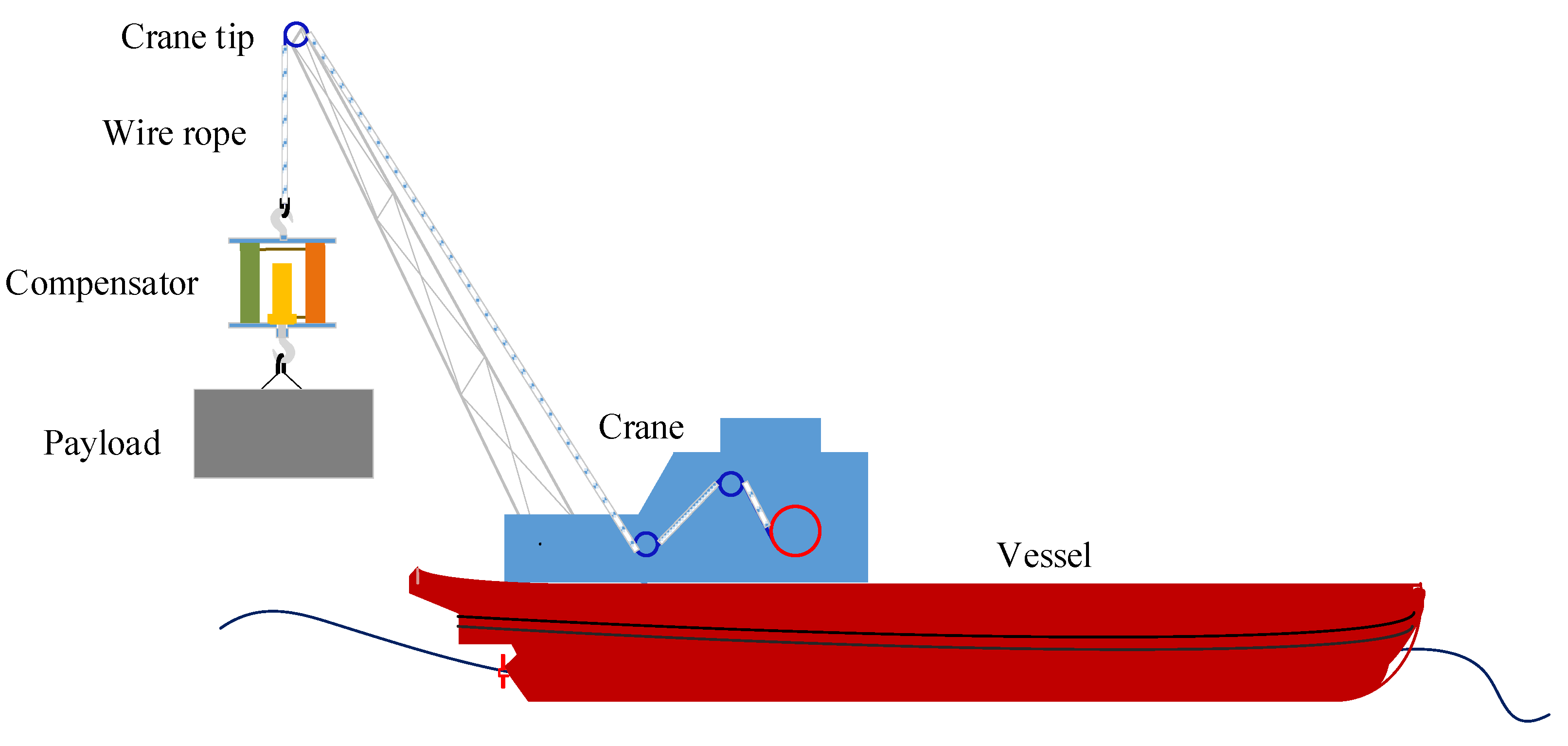
The schematic diagram of a typical offshore crane system with a passive heave compensator is shown in
Figure 1. The payload is lifted or lowered in the air. It is assumed that the crane is located on the crane vessel centerline and longitudinal center of gravity for minimal vessel motion. Due to wave disturbance, the vessel will experience surge, sway, heave, roll, pitch and yaw. Only the heave motion is considered in this paper, due to the central placement of the crane. The motion response of the payload is affected by the crane tip motion. The passive heave compensator is mounted in-line between the crane hook and the payload, which is used to reduce the payload motion and dynamic tension of the wire rope due to the crane tip motion in harsh sea.
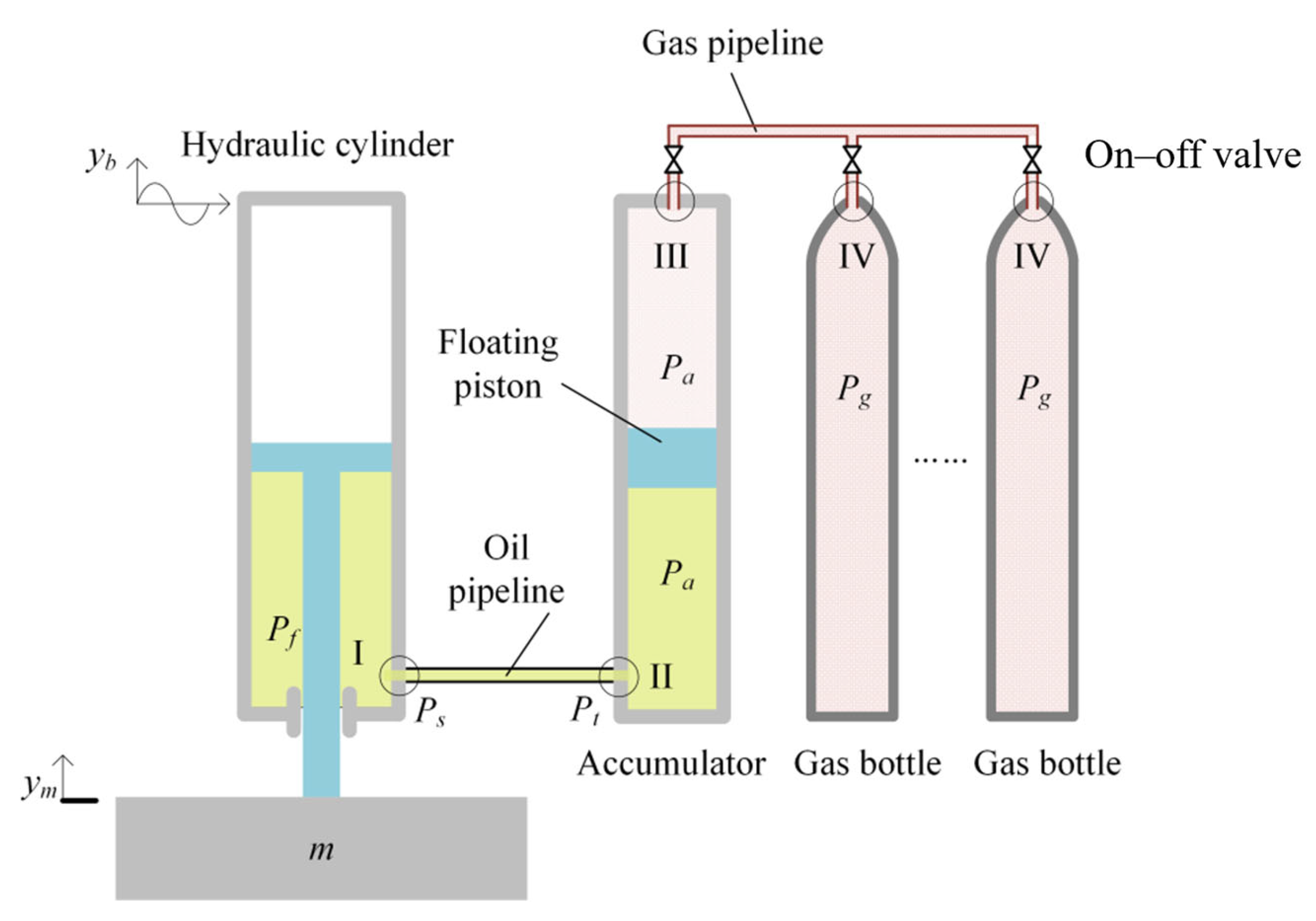
Figure 2 shows the schematic diagram of the studied passive compensator and variables used in this paper. A hydraulic cylinder, a piston accumulator, and several gas bottles form the key components of a passive heave compensator.
Inside the piston accumulator there is a floating piston, which divides the accumulator into the oil chamber and the gas chamber. Gas bottles with identical volume are used to obtain larger gas volume. And the gas bottles are connected by parallel pipelines to the piston accumulator. The gas chamber of the accumulator and the gas bottles are pressurized with Nitrogen so that the piston of the hydraulic cylinder can support the payload.
Under static conditions, the gas volume needs to be adjusted accordingly so as to set the piston of the hydraulic cylinder at the mid-stroke. And during operation, stiffness can be adjusted by changing the gas volume through an on–off valve to accommodate changes in ocean conditions and the payload.
The working principle of the passive heave compensator is explained as follows. When the vessel is excited by the wave, the vessel moves up and down in the heave direction. A pressure variation in the hydraulic cylinder oil chamber, resulting from the relative motion between the piston and the cylinder of the hydraulic cylinder, leads to an oil flow between the cylinder and the accumulator through the oil pipeline. The compensation effect is therefore obtained. For example, when the vessel moves upward, the pressure in the hydraulic cylinder is increased. Flows are caused by pressure differences between the hydraulic cylinder and the piston accumulator which push the oil from the point of higher pressure to the point of lower pressure. The pressure in the accumulator is increased, resulting in a compression of the gas inside the accumulator. Therefore, the piston rod of the hydraulic cylinder and the payload move vertically in opposition to the direction of vessel motion.
3. Mathematical Model of Passive Heave Compensator
In the following, a detailed mathematical model composed of the hydraulic cylinder, oil pipeline, the piston accumulator, gas pipeline and gas bottles is developed to predict the dynamic response of the passive heave compensator. To build a simplified and accurate model, the following assumptions are made in this paper.
The gas inside the compensator is treated as an ideal gas;
The hydraulic oil is incompressible;
The pressure of each gas bottles is equal;
The pressure in the upper chamber of the hydraulic cylinder is zero;
An adiabatic process is employed, since the heave motion of the vessel, with settling times on the order of seconds, is considered a fast system;
Assuming the flow area of the on–off valve is sufficiently large, the damping effect of the on–off valve is negligible.
3.1. Payload Model
In this paper, only the heave motion of the payload is considered. From Newton’s Second Law of Motion, the dynamic equation of the payload can be described by
where
m is the mass of the payload,
ym is the rod displacement of the hydraulic cylinder in the heave direction from static equilibrium position,
Pf is the instantaneous hydraulic pressure in chamber I,
Ff is the friction force of the hydraulic cylinder, and
Ap is the area difference between the piston and the rod of the hydraulic cylinder, which is expressed as
where
Dp is the piston diameter of the hydraulic cylinder, and
Dr is the rod diameter of the hydraulic cylinder.
3.2. Oil Pipeline Model
A pressure variation in the hydraulic cylinder oil chamber, resulting from relative movement, leads to an oil flow between the cylinder and the accumulator through the oil pipeline. When oil flows through the oil pipeline, there is a resistance effect due to a change in the geometry of the cross-section and friction. The resulting pressure drop contains two components, namely the major loss and the minor loss, which are modeled by the pressure–flow algebraic equation as the pipeline is short.
Minor losses take place in entrance I and entrance II due to a change in the geometry of the cross-section. The pressure losses in entrance I and entrance II can be expressed as
where
Ps,
Pt and
Pa are the instantaneous hydraulic pressures in the outlet of the entrance I, the inlet of the entrance II and the chamber II, respectively.
ρf is the mass density of the hydraulic oil.
Vi is the volumetric flow velocity of the hydraulic oil.
ξi and
ξa are minor loss coefficients;
ξi = 0.5 and
ξa = 1.
According to the Darcy–Weisbach equation, the major pressure loss in the oil pipeline due to friction can be expressed as
where
Dt is the inside diameter of the pipeline,
λ is the friction factor and
λ = 0.04.
Lt is the length of the oil pipeline.
From Equations (2) to (4), it is seen that both of the major pressure loss and the minor pressure loss are all a function of the volumetric flow velocity Vi of the hydraulic oil through the oil pipeline.
Under dynamic conditions, the piston of the hydraulic cylinder performs a relative axial motion induced by wave, and the resulting hydraulic oil flows between the hydraulic cylinder and the piston accumulator. Therefore, the volumetric flow velocity of the hydraulic oil is a function of the piston position, which is given by
where
yb is the displacement of the crane tip in the heave direction from the static equilibrium position.
3.3. Piston Accumulator Model
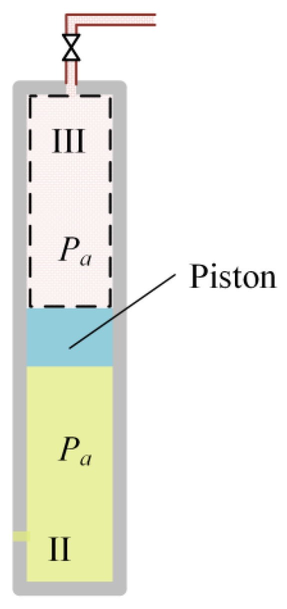
Figure 3 shows a sketch of a variable volume chamber of the piston accumulator. In the piston accumulator, the fluid chamber II is connected to the hydraulic cylinder, and the gas chamber III is connected to gas bottles by parallel pipelines. The dashed line contains the variable volume of gas considered in this section.
The floating piston mass is neglected, as compared to the external load of the compensator it is too small. And assume that the floating piston can slide without friction. Thus, the pressures in chamber II and chamber III can be assumed to be the same at any given instant. Let Pa denote the instantaneous pressure in chamber II and in chamber III.
In the operation process, any increase in pressure in the gas chamber of the piston accumulator causes the entry of gas in the gas bottles. Vice versa, at every drop of pressure in the accumulator, the gas contained in the gas bottles flows back to the piston accumulator. As the gas flows in and out of the piston accumulator, the gas state in the chamber III changes dynamically. Temperature θa, pressure Pa and volume Va quantitatively define the state of the gas in the piston accumulator.
The gas chamber of the piston accumulator is modeled as an open system with changing mass and volume. The pressure
Pa in the accumulator, at a volume
Va and temperature
θa, can be described by [
21]
where
ma is the instantaneous mass of Nitrogen in chamber III.
The derivative of temperature
θa with respect to time is then
where
is the mass flow velocity of Nitrogen.
The pressure variation with respect to time can be defined as follows [
22]:
where
n is adiabatic coefficient (
n = 1.4 for Nitrogen).
Substituting
into Equation (8),
3.4. Gas Pipeline Model
When the compensator is excited by the wave, the gas inside the compensator is compressed or expanded. Pressure differences arise and gas exchanges through the pipeline between the accumulator and the gas bottles. When
Pa >
Pg, the gas streams from the accumulator to the gas bottles. When
Pa <
Pg, the gas streams in the opposite direction. The mass flow velocity
Ga through the gas pipeline connecting the piston accumulator and the gas bottles can be defined as
where
and
R is the gas constant of Nitrogen.
Se is the effective cross-section of the pipeline expressed with the following formula:
where
α is the coefficient of contraction, and
α ∊ [0.85, 0.95],
Dg is the diameter of the gas pipeline.
3.5. Gas Bottle Model
Gas exchanges between the piston accumulator and the gas bottles through the gas pipeline. The total mass flow velocity in the gas pipeline is the sum of that into the gas bottles. For simplicity, it is assumed that the gas in the gas bottles has uniform temperature, pressure and density. Thus, all gas bottles have identical mass flow velocity. Let
ψ be the number of the gas bottles, and the following equation is valid:
where
Gb is the mass flow velocity into or out of one of the gas bottles.
The gas in the gas bottle is considered as being a constant volume with variable mass, since there is no volume change associated with the gas bottle. Thus, temperature
θa and pressure
Pa quantitatively define the state of the gas in the gas bottles. For a given constant volume, pressure
Pa and temperature
θa can be, respectively, defined as [
23]
where
Vg is the volume of the gas bottle.
Equations (1)–(11) characterize the passive heave compensator. The input to the compensator is the displacement of the crane tip yb. The problem of the passive heave compensator design can be formulated as that to determine the gas volume, piston diameter of the hydraulic cylinder and so on so as to guarantee that the passive heave compensator provides the desirable performance.
4. Simulation Analysis
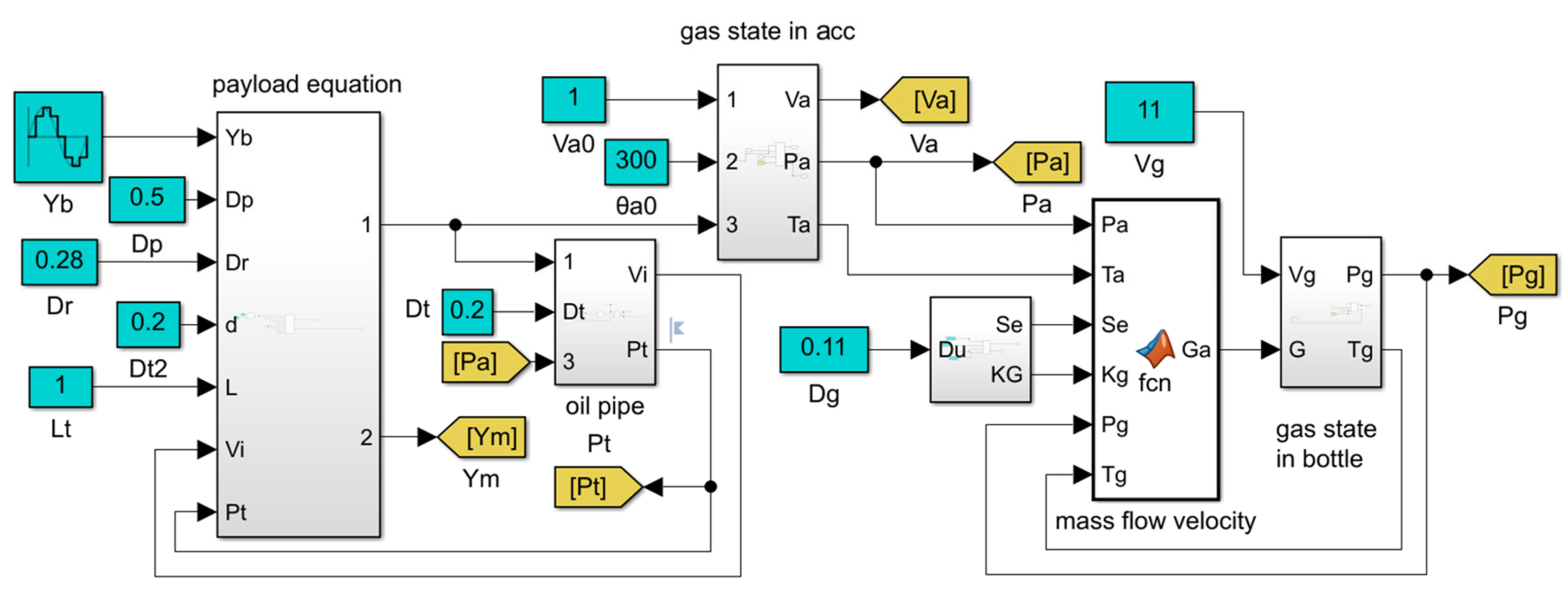
In this section, numerical simulations using the proposed mathematical model of the passive heave compensator involving Equations (1)–(4), (6)–(11) are carried out in Matlab/Simulink to obtain further insight into the influence of the main design parameters on the dynamic response of the passive heave compensator. The simulation block diagram of the proposed model is shown in
Figure 4. The time range of each simulation is 10,000 s. And, the ordinary differential equation function solver ODE45 is used.
In the previous papers, numerous numerical simulations have been conducted to evaluate the effect of the design parameters on the performance of the passive heave compensator, such as the piston diameter of the hydraulic cylinder, the total gas volume and so on. Therefore, the focus of the following numerical simulations is to analyze the influence of the accumulator volume and the diameters of gas pipeline and hydraulic oil pipeline on the dynamic response of the passive heave compensator.
In the numerical simulations, the vessel motion is given by Equation (12).
where
A = 2.5 m and
T = 6 s denote the amplitude and frequency, respectively.
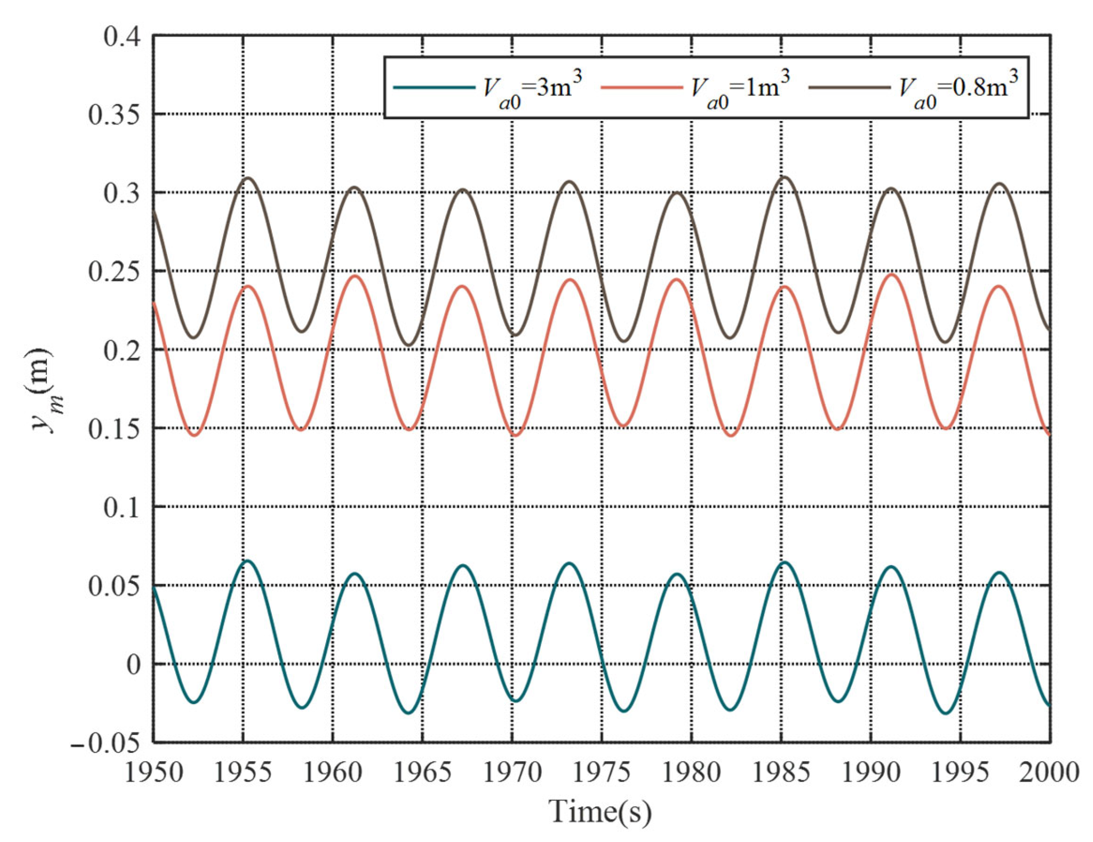
The effects of the volume of the piston accumulator upon the dynamic response of the passive heave compensator are investigated in this section. In the numerical simulations, the total gas volume is 12 m3, which is stored in the gas bottles and the piston accumulator. And three different initial gas volumes of the piston accumulator are considered in the simulations, which are 3 m3, 1 m3 and 0.8 m3.
The simulation results are shown in
Figure 5. The parameters are
m = 250,000 kg,
Va0 +
Vg = 12 m
3,
Dp = 0.5 m,
Dr = 0.28 m,
Dt = 0.2 m,
Lt = 1 m, and
Dg = 0.1 m, where
Va0 is the initial gas volume in the piston accumulator. From this figure, the relationship can be described as follows. When
Vas = 3 m
3, the payload oscillates about the static equilibrium position. However, when
Vas = 1 m
3 and
Vas = 0.8 m
3, the payload oscillates about the new equilibrium positions, which are slightly higher than the static equilibrium position. It can be concluded that as the accumulator volume decreases, the oscillation center moves up relative to the static equilibrium position since the passive heave compensator exhibits stronger nonlinearity.
The results reveal that making the volume of the accumulator as large as possible under permitted circumstances can make the oscillation center more toward the midpoint of the hydraulic cylinder, increasing the travel range of the passive heave compensator.
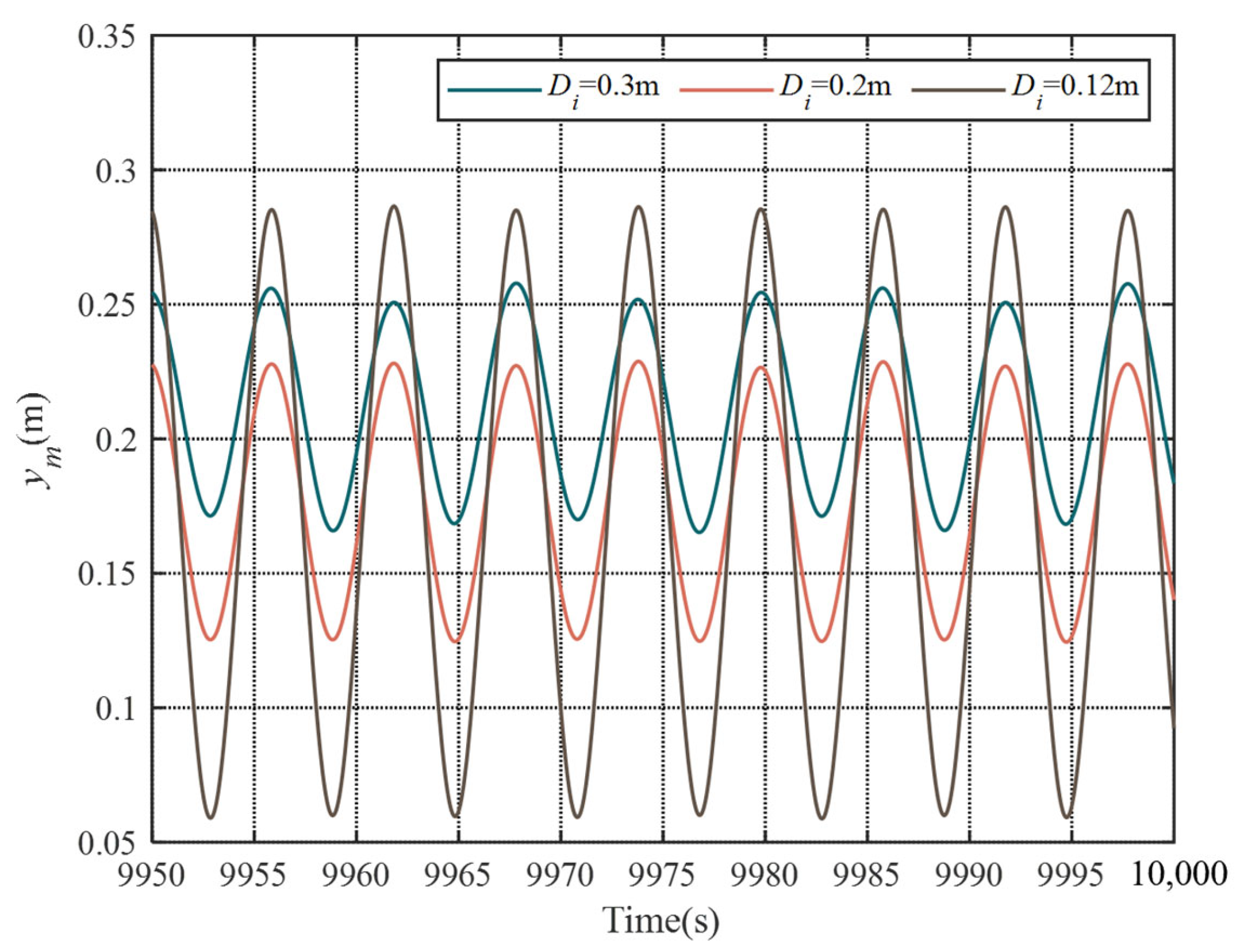
The simulation results for the diameter of the oil pipeline 0.3 m, 0.2 m and 0.12 m are shown in
Figure 6. The parameters are
m = 250,000 kg,
Va0 = 1 m
3,
Vg = 11 m
3,
Dp = 0.5 m,
Dr = 0.28 m,
Dt = 1 m,
Dg = 0.1 m and
Lt = 1 m. It may be seen that, by increasing the diameter of the oil pipeline, a substantial increase in the compensation efficiency can be achieved. It is to be noted that the diameter of the oil pipeline also has an effect on the position of the oscillation center of the payload. With an increasing the diameter of the pipeline, the oscillation center of the payload moves up.
The effect of the diameter of the gas pipeline on the dynamic response of the passive heave compensator is shown in
Figure 7. The parameters are
m =250,000 kg,
Va0 = 1 m
3,
Vg = 11 m
3,
Dp = 0.5 m,
Dr = 0.28 m and
Lt = 1 m. It is observed that, as a result of decreasing the diameter of the gas pipeline, the compensation efficiency is obviously improved. This simulation result is not consistent with the fact that decreasing pipeline diameter leads to increasing damping and therefore a reduction in the compensation efficiency of the passive heave compensator. This occurs because, when a smaller pipeline is used, the oscillation center moves up relative to static equilibrium position, which leads to an increase in the accumulator gas volume and, therefore, an improvement in the compensation efficiency of the passive compensator.
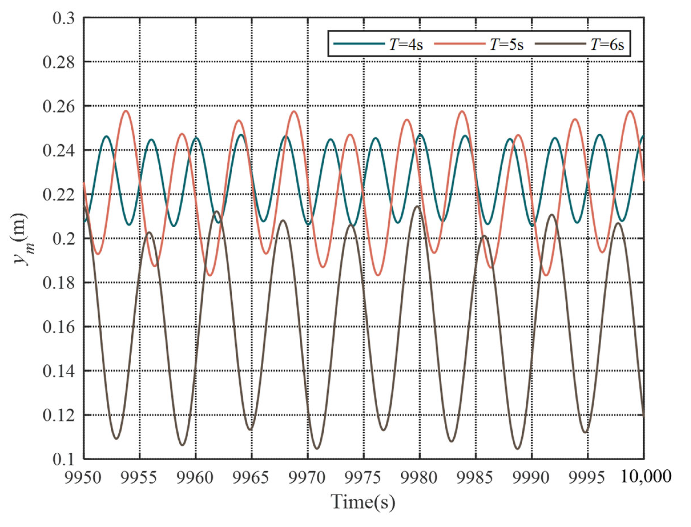
The payload displacement is plotted in
Figure 8 for three different excitation periods of 4 s, 5 s and 6 s. The parameters are
m = 250,000 kg,
Va0 = 1 m
3,
Vg = 11 m
3,
Dp = 0.5 m,
Dr = 0.28 m,
Dt = 0.2 m,
Lt = 1 m, and
Dg = 0.11 m.
Figure 7 demonstrates that decreasing the excitation period reduces payload displacements. This phenomenon occurs because shorter excitation periods increase the dynamic force magnitude acting on the passive heave compensator, thereby generating greater displacement in the passive heave compensator and consequently improving its compensation efficiency. Under the condition of constant gas pipeline damping, the large gas volume causes slow pressure variations. This results in greater gas flow toward the piston accumulator compared to the gas bottles, until a new equilibrium state is established. Consequently, the oscillation center positions move upward relative to the static equilibrium position.
The simulation results reveal two key findings:
The piston accumulator gas volume critically influences the passive compensator performance, namely compensation efficiency and oscillation center location;
Increasing the piston accumulator gas volume offers operational benefits by stabilizing the oscillation center position and enhancing compensation efficiency.
5. Conclusions
In this paper, a nonlinear dynamic model of the passive heave compensator has been developed considering the thermodynamics of the gas exchange process between the piston accumulator and the gas bottles. The main contribution of this paper is as follows: the proposed model provides a more accurate model to predict the dynamic characteristics of the passive heave compensator, particularly the gas thermodynamics of gas exchange between the piston accumulator and the gas bottles. Numerical simulations for the developed model are carried out to analyze the effects of key design parameters on the dynamic response of the compensator. The simulation results indicate that by increasing the diameter of the oil pipeline or decreasing the diameter of the gas pipeline, a substantial increase in the compensation efficiency can be achieved. Meanwhile, the initial gas volume of the piston accumulator has a significant effect on the performance of the passive compensator not only via the compensation efficiency but also via the location of the oscillation center. A piston accumulator with a larger gas volume is advantageous since it leads to relatively small change of the location of the oscillation center and high compensation efficiency. When the initial gas volume of the piston accumulator increases from 0.8 m3 to 1 m3, the oscillation center decreases by about 20%. Therefore, the accumulator volume must be carefully chosen. It is noted that the location of the oscillation center is changed through the coupling of different parameters, such as accumulator volume and gas pipeline diameter.
Author Contributions
Conceptualization, Y.Z., M.H., Y.Y., J.J., B.Y. and D.Q.; methodology, Y.Z., M.H. and Y.Y.; software, B.Y. and D.Q.; validation, M.H., J.J. and D.Q.; formal analysis, Y.Z. and M.H.; investigation, Y.Z. and J.J.; resources, B.Y. and D.Q.; data curation, M.H. and Y.Y.; writing—original draft preparation, Y.Z. and M.H.; writing—review and editing, D.Q. and Y.Y.; visualization, Y.Z. and. J.J.; supervision, Y.Z. and B.Y.; project administration, Y.Z. and M.H.; funding acquisition, Y.Z. and D.Q. All authors have read and agreed to the published version of the manuscript.
Funding
This work was supported by the Foundation Strengthening Plan Technology Field Fund Project under Grant 2021-JCJQ-JJ-0301.
Data Availability Statement
The original data contributions presented in the study are included in the article; further inquiries can be directed to the corresponding authors.
Conflicts of Interest
The authors declare no conflicts of interest.
References
- Woodacre, J.K.; Bauer, R.J.; Irani, R.A. A review of vertical motion heave compensation systems. Ocean Eng. 2015, 104, 140–154. [Google Scholar]
- Nam, B.W.; Kim, N.W.; Hong, S.Y. Experimental and numerical study on coupled motion responses of a floating crane vessel and a lifted subsea manifold in deep water. Int. J. Nav. Archit. Ocean Eng. 2017, 9, 552–567. [Google Scholar]
- Collins, M.D. Applications of a Motion Compensation Stabilized Vertical Array of Hydrophones. IEEE Access 2019, 7, 79433–79437. [Google Scholar] [CrossRef]
- Jaculli, M.A.; Leira, B.J.; Sangesland, S.; Morooka, C.K.; Mendes, J.R.P. Dynamic Behavior of a Novel Heave-Compensated Floating Platform for Well Interventions. In International Conference on Offshore Mechanics and Arctic Engineering; American Society of Mechanical Engineers: New York, NY, USA, 2020; Volume 84430, p. V011T11A051. [Google Scholar]
- Lee, H.; Roh, M.I.; Ham, S.H.; Ha, S. Dynamic simulation of the wireline riser tensioner system for a mobile offshore drilling unit based on multibody system dynamics. Ocean Eng. 2015, 106, 485–495. [Google Scholar] [CrossRef]
- Kang, H.S.; Kim, M.H.; Aramanadka, S.S.B. Tension variations of hydro-pneumatic riser tensioner and implications for dry-tree interface in semisubmersible. Ocean Syst. Eng. 2017, 23, 21–38. [Google Scholar] [CrossRef]
- Chen, B.; Yu, J.; Yu, Y.; Xu, L.; Hao, S.; Wu, C.; Wu, H. Study on performance parameters of hydro-pneumatic tensioner for top tensioned riser. Appl. Ocean Res. 2019, 84, 206–215. [Google Scholar] [CrossRef]
- Duc, L.V.; Trong, N.K. Combination of input shaping and radial spring-damper to reduce tridirectional vibration of crane payload. Mech. Syst. Signal Process. 2019, 116, 310–321. [Google Scholar]
- Quan, W.; Liu, Y.; Zhang, A.; Zhao, X.; Li, X. The nonlinear finite element modeling and performance analysis of the passive heave compensation system for the deep-sea tethered ROVs. Ocean Eng. 2016, 127, 246–257. [Google Scholar]
- Gao, H.; Chi, M.; Zhu, M.; Liu, D.; Lin, J. Study on Air Spring Model. J. Mech. Eng. 2015, 51, 108–115. [Google Scholar]
- Cuellar Sanchez, W.H.; Linhares, T.M.; Neto, A.B.; Fortaleza, E.L.F. Passive and semi-active heave compensator, Project design methodology and control strategies. PLoS ONE 2017, 12, e0183140. [Google Scholar]
- Woo, N.S.; Kim, H.J.; Han, S.M.; Ha, J.H.; Huh, S.C.; Kim, Y.J. Evaluation of the Structural Stability of a Heave Compensator for an Offshore Plant and the Optimization of Its Shape. J. Nanosci. Nanotechnol. 2020, 20, 263–269. [Google Scholar] [CrossRef] [PubMed]
- Haaø, J.; Vangen, S.; Choux, M.; Hovland, G.; Hansen, M.R. The effect of friction in passive and active heave compensators of crown block mounted compensators. IFAC Proc. Vol. 2012, 45, 316–320. [Google Scholar] [CrossRef]
- Sánchez, W.H.C.; Neto, A.B.; Fortaleza, E.L.F. Effects of nonlinear friction of passive heave compensator on drilling operation—Part I: Modeling and analysis. Ocean Eng. 2020, 213, 107743. [Google Scholar] [CrossRef]
- Sánchez, W.H.C.; Fortaleza, E.; Neto, A.B.; Fortaleza, E.L.F. Effects of nonlinear friction of passive heave compensator on drilling operation—Part II: Active robust control. Ocean Eng. 2021, 227, 108837. [Google Scholar]
- Yu, H.; Wei, J.; Fang, J.; Sun, G.; Zhang, H. Predictive robust control based on higher-order sliding mode for passive heave compensator with hydraulic transformer. In Symposium on Fluid Power and Motion Control; American Society of Mechanical Engineers Digital Collection: New York, NY, USA, 2018. [Google Scholar]
- Cannell, D.; Miller, C.; Riddell, S.; Gonsholt, S.V.; Sannes, S. Adaptive Passive Heave Compensation Systems-The Next Generation. Offshore Technology Conference Asia, Kuala Lumpur, Malaysia, 22–25 March 2016; Offshore Technology Conference: Houston, TX, USA, 2016. [Google Scholar]
- Yi, B.; Zhan, Y.; Xu, J. Dynamic analysis and optimization of a novel Dual-valve heave compensator for heavy lifting operations. Ocean Eng. 2024, 309, 118528. [Google Scholar] [CrossRef]
- Xu, J.; Yi, B.; Zhan, Y. A semi-analytical method of passive heave compensator for the splash zone crossing: Modeling and application. Ocean Eng. 2023, 286, 115613. [Google Scholar] [CrossRef]
- Xu, J.; Yi, B.; Zhan, Y. Review of heave compensation systems: Design and control strategies. 2023 IEEE 11th International Conference on Computer Science and Network Technology (ICCSNT), Dalian, China, 21–22 October 2023; IEEE: New York, NY, USA, 2023; pp. 406–413. [Google Scholar]
- Wang, J.; Zhu, S.; He, L. Research on vibration characteristics of air spring with auxiliary chamber based on complex stiffness. Chin. Mech. Eng. 2009, 20, 1418–1422. [Google Scholar]
- Wang, J.S.; Zhu, S.H. Linearized model for dynamic stiffness of air spring with auxiliary chamber. J. Vib. Shock 2009, 28, 72–76. [Google Scholar]
- Cai, M. Theory and Practice of Modern Pneumatic Technology (2). Hydraul. Pneum. Seals 2007, 27, 43–47. [Google Scholar]
| Disclaimer/Publisher’s Note: The statements, opinions and data contained in all publications are solely those of the individual author(s) and contributor(s) and not of MDPI and/or the editor(s). MDPI and/or the editor(s) disclaim responsibility for any injury to people or property resulting from any ideas, methods, instructions or products referred to in the content. |
© 2025 by the authors. Licensee MDPI, Basel, Switzerland. This article is an open access article distributed under the terms and conditions of the Creative Commons Attribution (CC BY) license (https://creativecommons.org/licenses/by/4.0/).


