Abstract
Offshore wind turbines (OWTs) exhibit inherent directional variations in inertia, stiffness, and damping properties. This study examines the directionality effect of a 10 MW monopile-supported OWT using an integrated rotor-nacelle assembly (RNA) and support structure model. Through combined theoretical analysis and numerical simulations, this paper systematically investigates the following: (1) the anisotropic characteristics of RNA rotational inertia and blade stiffness, (2) the natural frequency and aerodynamic damping properties of the system, and (3) the directional mechanisms governing seismic responses of MOWTs during parked and running states. The key findings reveal substantial structural anisotropies. The second-order natural frequencies display a 15% disparity between fore–aft (1.43 Hz) and side–side (1.24 Hz) tower modes. The blade frequencies show over 50% differences between flap-wise (0.60 Hz/1.69 Hz) and edge-wise (0.91 Hz/2.71 Hz) modes in first-/second-order vibrations. Moreover, the aerodynamic damping ratios show marked directional contrast, with first-mode fore–aft damping (8%) exceeding side–side values (1.11%) by a factor of 7.2. Consequently, the seismic input directionality induces peak yaw-bearing bending moment variations of 38% (running condition) and 73% (parked condition). The directional effects in parked OWTs are attributed to RNA inertia anisotropy and blade stiffness disparities, while the running condition demonstrates combined influences from inherent system parameters (inertia, stiffness, aerodynamic damping) and wind–wave environmental loading.
1. Introduction
The exacerbation of the global energy crisis coupled with heightened environmental consciousness has positioned wind energy as a critical renewable component in the modern energy system [1]. According to the Global Wind Energy Council 2023 market report, global wind power installations reached a record of 75.2 GW in new capacity [2]. Particularly, offshore wind energy has entered a phase of accelerated development. However, the proliferation of marine wind projects has resulted in a pronounced shortage of viable nearshore locations near major economic zones, necessitating the development of offshore wind farms in seismically active regions [3]. This geographical shift has elevated seismic load analysis to a critical research priority for offshore wind turbine (OWT) structural safety, prompting concerted efforts across industry entities [4] and academic institutions [5,6,7].
The offshore wind turbine (OWT) is a complex dynamic system consisting of a wind turbine and support structure. The existing research shows the greatest differences in structural modeling approaches for wind turbines. Hacıefendioğlu and Bayraktar [8] simplified monopile-supported offshore wind turbines (MOWTs) into axisymmetric systems by modeling the rotor-nacelle assembly (RNA) as a concentrated mass at the tower top, performing seismic response analysis. This model has been widely adopted [9,10,11] through theoretical analyses [12,13], numerical simulations [14,15], and physical experiments [16,17], and supporting studies on the seismic responses of fixed-bottom OWTs [18,19], vulnerability analysis of the support structure [20,21], and a reliability evaluation of the system [22]. These findings highlight that seismic loads may govern the structural design in earthquake-prone regions.
The deployment of multi-megawatt OWTs has driven advancements in refined RNA modeling. The current methodologies employ discrete concentrated masses at the tower-top to independently represent rotor and nacelle components, with rotational inertia explicitly integrated into the tower-top mass to improve the inertial effect characterization [23,24]. In blade stiffness modeling, prevailing studies typically idealize blades as equivalent tapered beam elements [25,26], though high-fidelity simulations utilizing shell-element formulations have recently emerged to better capture complex dynamic behaviors [27,28]. While these modeling strategies account for directional variations in rotational inertia and stiffness, their coupled effects on the seismic response mechanisms of OWTs remain insufficiently explored.
The directional uncertainty of seismic inputs at engineering sites, originating from the source mechanism complexity and wave propagation path heterogeneity, has emerged as a critical consideration in seismic engineering [29]. Extensive research confirms that omitting directional effects in ground motion may induce non-negligible deviations in assessment in structural response predictions and fragility assessments [30,31]. For MOWTs, although their support structures are nominally axisymmetric, the inherent FA and SS directional stiffness asymmetry in blade systems combined with tower-top mass eccentricity induces significant directional dependence in dynamic characteristics. Arany et al. [32] conducted modal analyses of MOWTs, identifying systematic frequency discrepancies between FA and SS vibration modes. Furthermore, full-scale monitoring campaigns of running OWTs have quantified distinct damping ratios in FA versus SS directions [33]. Under the running condition, the multi-physics coupling of wind–wave–current excitations with directionally variable seismic components creates intricate dynamic interactions. Alati et al. [34], through systematic investigation of jacket-supported OWT responses under swapped FA/SS ground motion orientations, established the critical necessity of averaging directional seismic demands in structural design. These collective insights underscore the methodological imperative to rigorously quantify directional effects in OWT seismic performance evaluations.
The existing investigations have demonstrated significant directional dependence in seismic responses of onshore wind turbines [35,36,37]. Subsequently, Yang et al. [38] implemented soil–structure interaction in FAST software (V7) for NREL 5 MW MOWTs, revealing a 40% deviation in tower-top displacements and mudline bending moments under multidirectional seismic inputs, though limited to a single ground motion record. Using OpenSees, Mo et al. [39] established a 3D MOWT model with separated rotor-nacelle masses, identifying significant seismic response variations with horizontal ground motion angles. Romero-Sánchez and Padrón LA [40] developed a pile–soil interaction module in OpenFAST for jacket-type OWTs, showing that seismic directionality critically influences jacket internal forces, with critical directions varying across response parameters. Collectively, these studies establish directional dependence in fixed-bottom OWT seismic responses and fragility while highlighting insufficient exploration of parameter-specific directionality patterns.
The existing research on directional seismic effects in wind turbines predominantly examines five MW models. However, as the wind power industry advances, 10 megawatt turbines are increasingly deployed. In addition, existing findings show inconsistencies. For example, for parked MOWTs, Wang and Dong [35] suggested that the most unfavorable seismic direction occurs in the SS direction, while Xi et al. [41] argued that the most unfavorable direction depends on the input seismic motion characteristics. Furthermore, while directional input parameterization has been extensively studied, no research has specifically addressed the mechanisms governing direction-dependent seismic responses and the degree of influence exerted by various factors. These research gaps hinder the development of offshore wind farms in high seismic hazard regions.
To address these research gaps, this study employs the DTU 10 MW MOWT as a case study to (1) investigate the underlying factors contributing to directional seismic response effects, and (2) systematically quantify their relative influence through parametric analysis. This paper is organized as follows: Section 2 details turbine parameters, site conditions, and directional variations in blade stiffness and RNA rotational inertia. Section 3 illustrates the numerical model and methodology employed in this study. Section 4 analyzes the natural frequencies, aerodynamic damping, and seismic responses of the MOWT to identify key directional drivers, with conclusions in Section 5. The flow chart of this paper is shown in Figure 1. This study provides valuable insights for accurately predicting seismic responses of 10 MW offshore wind turbines, with potential implications for enhancing seismic design methodologies in offshore renewable energy engineering.
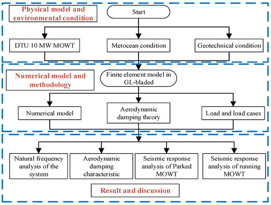
Figure 1.
Flow chart for this paper.
2. Physical Model and Environmental Condition
2.1. 10 MW MOWT
The seismic response analysis of MOWTs in this investigation employs the DTU 10 MW reference turbine [42] as the baseline model. A custom-designed controller and site-optimized monopile foundation [43] were integrated into this wind turbine. The key parameters are tabulated in Table 1, with comprehensive validation data available in the technical specification [42].

Table 1.
Main properties of DTU10 MW wind turbine.
A global coordinate system defined by orthonormal basis vectors (x, y, z) is established for dynamic characterization, as illustrated in Figure 2. The coordinate origin is positioned at the intersection point between the mean sea level and the axis of the monopole. The coordinate axes obey the following convention: (1) the x-axis aligns with the predominant wind inflow direction; (2) the z-axis coincides with the undeformed structural axis (positive upward); and (3) the y-axis completes the right-handed triad via the cross product . A local coordinate system (ζ, η, γ) is embedded at the RNA mass center, with its basis vectors maintaining parallelism to the global coordinate system: . This kinematic convention ensures consistent transformation between the global and local reference frames throughout dynamic simulations.
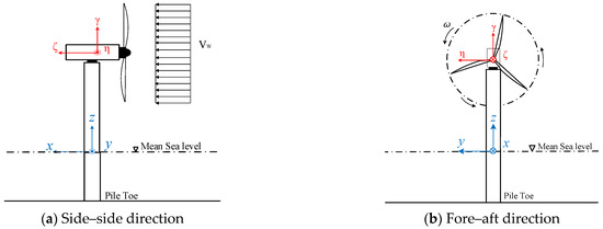
Figure 2.
Coordinate system of analysis.
Modern wind turbines typically incorporate airfoil cross-sections, exhibiting marked discrepancies in the area moments of inertia between their principal (strong) and secondary (weak) axes. Figure 3 illustrates the span-wise distribution of flap-wise (out of rotor plane) and edge-wise (in rotor plane) stiffness for the DTU 10 MW wind turbine blade. The bending stiffness in both directions exhibits a monotonically decreasing trend along the blade span from the root to the tip. Notably, the edge-wise stiffness exceeds the flap-wise stiffness within the region spanning 10 m from the blade root to the tip. At specific locations (20 m, 40 m, and 60 m from the root), the edge-wise stiffness values are measured to be 2.1, 3.4, and 3.9 times those of the flap-wise stiffness, respectively. It is evident that the blade stiffness exhibits substantial differences in these two directions. To systematically characterize the stiffness disparity, the average blade stiffness is calculated using Equation (1):
where represents the average blade stiffness, denotes the span-wise bending stiffness distribution, r is the radial coordinate from the blade element to the blade root, and L is the total blade length (from root to tip). The numerical integration yields for flap-wise bending and for edge-wise bending, revealing a stiffness disparity ratio .
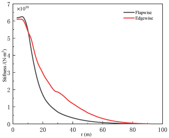
Figure 3.
Stiffness distribution of the blade.
The rotor of a wind turbine is composed of the assembly of blades connected to the hub, creating a planar geometric configuration. The nacelle, characterized by its cuboid geometry, exhibits substantial disparities in rotational inertia about its principal centroid axes. As summarized in Table 2, the RNA of the DTU 10 MW wind turbine demonstrates a significant anisotropy in rotational inertia, with the moment of inertia about the ζ-axis (Iζ = 2.89 × 10⁸ kg·m²) exceeding that about the η-axis (Iη = 1.81 × 10⁸ kg·m²) by a factor of 1.6. This inertial anisotropy has critical implications for the MOWT: while the support structure maintains symmetry, the combined effects of stiffness distribution and RNA inertial asymmetry result in system-level dynamic anisotropy. Such coupled effects may manifest as eigenfrequency splitting phenomena and directional dependence in dynamic responses of MOWTs.
Table 2.
The rotational inertia of the rotor-nacelle assembly.
2.2. Geotechnical Condition
The monopile of the 10 MW OWT was designed according to the representative marine site shown in Figure 4. The geotechnical parameters in the figure include γs (effective unit weight of soil), k0 (initial modulus of soil reaction), and Φ (internal friction angle). A local coordinate system (xL, yL, zL) was established to define site-specific soil resistance parameters, with its origin positioned at the intersection of the monopile axis and mudline. The xL- and yL-axes lie in the horizontal plane, while the zL-axis aligns vertically downward along the monopile axis.
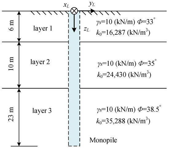
Figure 4.
Soil layer of marine site.
The foundation design features a monopile with a 7.8 m outer diameter, an 85 mm wall thickness, and a 39 m effective embedded depth. This configuration satisfies ultimate limit state (ULS) requirements for bearing capacity, serviceability limit state (SLS) criteria, and fatigue resistance. Based on these validations, the current site configuration has been selected for dynamic analysis in this investigation.
The soil–structure interaction is modeled using the p-y curve approach. For large-diameter monopile applications, the horizontal soil resistance follows the modified p-y formulation developed by Sun et al. [44], expressed by Equation (2):
where A is a factor accounting for the cyclic or static loading conditions, evaluated by A = 0.9 for cyclic loading; is the ultimate lateral resistance; z0 = 2.5 m is the reference depth; zL is the depth below the original seafloor; y is the lateral deflection; D is the monopile outside diameter; D0 = 1.0 m is the reference diameter of the monopile; and m = 0.5 and n = 0.6 are dimensionless coefficients. The axial soil spring resistance curve of the pile shaft and the tip soil spring resistance curve follow the formulations recommended by the API (American Petroleum Institute) [45], which are not elaborated here.
2.3. Metocean Conditions
The vertical wind speed profile is modeled through Equation (3), according to the IEC 61400-3 standard [46]:
where Vhub represents the mean wind speed at the hub height, α = 0.14 is the power law exponent, ξ represents elevation above mean sea level, and ξr = 119 m indicates hub height. Turbulent wind components are modeled using the Kaimal spectrum with class B turbulence intensity (Iref = 0.14) [47]. A three-dimensional wind field with a 600 s duration is generated through stochastic simulation with phase randomization.
The environmental parameters are derived from the IJmuiden metocean data, establishing the relationship between hub-height mean wind speed Vhub, significant wave height HS, and spectral peak period TP as tabulated in Table 3. The JONSWAP spectrum [48] as denoted in Equation (4) is used to generate the wave time histories.
where denotes the angular frequency of the wave, and represents the angular frequency corresponding to the spectral peak period Tp; for and when ; is the peak parameter and can be determined by Equation (5):
Table 3.
Relation between wind and wave parameters.
3. Numerical Model and Methodology
The OWTs constitute a complex system integrating mechanical and structural components. The directional effects are investigated in the following analysis primarily through numerical simulations. This section describes the essential numerical models, methodologies, and load cases employed in the study.
3.1. Numerical Model
This study employed GL-Bladed (V4.8) software to perform eigenfrequency analysis and dynamic response characterization of the system. Figure 5 displays the analysis model of the DTU 10 MW MOWT. The structural dynamics of the blades, tower, and monopile were modeled using the Euler–Bernoulli beam theory [49], with discretization resolutions of 21 two-node beam elements per blade, 55 two-node beam elements for the monopile, and 21 two-node beam elements for the tower. The nodes of each component are uniformly distributed. The mesh convergence studies confirm that the adopted discretization density ensures less than 5% error in modal parameters and dynamic response predictions.
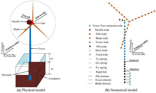
Figure 5.
Finite element model of the DTU 10 MW MOWT.
For the natural frequencies analysis, the RNA is idealized as a rigid body at the tower-top in the GL-Bladed implementation, with the soil–structure interaction modeled through p-y curve-derived spring stiffness coefficients using the initial tangent method. In the blade modal analysis, a clamped boundary condition is imposed at the blade root while maintaining rotor stationarity, thereby excluding centrifugal stiffening effects.
3.2. Aerodynamic Damping Theory
The aerodynamic damping calculation method for horizontal-axis wind turbines proposed in the literature [50] follows a systematic procedure based on the blade element momentum (BEM) theory. First, the aerodynamic loads acting on the rotor are calculated using BEM. These distributed loads are then decomposed into aerodynamic damping through a first-order Taylor expansion, as visualized in Figure 6a. In this figure, dpN and dpτ, respectively, denote the normal and tangential aerodynamic damping forces acting along the blade span. Subsequently, the aerodynamic damping forces are transferred to the hub center through spatial reduction. This process yields the resultant aerodynamic damping forces and moments in the hub’s translational and rotational directions (Fdx, Fdy, Mdx, Mdy), as represented in Figure 6b. These aerodynamic drag forces are proportional to the motion velocity at the hub center, exhibit characteristics of a viscous damping model, and can be expressed by Equations (6)–(9):
where Fdx and Fdy are the resultant aerodynamic damping forces along the x- and y-directions at the hub center, respectively; Mdx and Mdy are the resultant aerodynamic damping moments about the x- and y-directions at the hub center, respectively; cx and cy represent the viscous damping coefficients of the translational dampers along the x- and y-directions at the hub center, respectively; and cα and cβ denote the viscous damping coefficients of the rotational dampers about the x- and y-directions at the hub center, respectively.
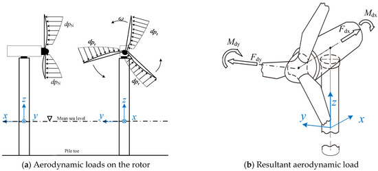
Figure 6.
Simplification of aerodynamic damping loads on the rotor.
Based on the derived force/moment components, equivalent viscous damping coefficients are determined using Equations (10)–(13):
where Nb is the blade number of the rotor; and are the distributed aerodynamic loadings on the blade along the tangential and normal direction of the rotor, respectively; ρ is the air density, c(r) is the airfoil chord length; Vx and Vr are the normal and tangential components of the relative wind velocity, respectively; , , CL and CD represent the derivatives of the lift coefficient and drag coefficient; and the relative wind inflow angle φ is the sum of the angle of attack (α(r,t)), pitch angle (βp(t)), and twist angle (k(r)). The formulation establishes two translational damping coefficients (corresponding to Fdx and Fdy) and two rotational damping coefficients (associated with Mdx and Mdy), effectively modeling the system through a combination of viscous dampers in these four degrees of freedom.
To systematically quantify the aerodynamic damping disparity between the FA and SS directions in the 10 MW MOWT, the modal aerodynamic damping ratio is derived from Equation (14):
where represents the aerodynamic damping ratio of the i-th mode in either the FA or SS direction for the 10 MW MOWT; is the corresponding mode shape vector, and denotes its transpose; is the damping matrix, where only the contribution of aerodynamic damping is considered here; is the modal mass of the i-th mode; and is the circular frequency of the i-th mode.
3.3. Load and Load Cases
3.3.1. Aerodynamic Load
The aerodynamic loading serves as the principal excitation source for running OWTs. The present investigation implements the BEM theory for aerodynamic load computation, with a particular emphasis on three modeling considerations. First, a convergence threshold of 1 × 10⁻⁴ is imposed on axial and tangential wind speed induction factors throughout the iterative solution process. Second, the dynamic wake effect is addressed using the Øye viscous wake model [51], supplemented by the Beddoes–Leishman dynamic stall formulation [52] to capture unsteady flow separation characteristics under incompressible flow conditions. Third, three-dimensional flow corrections are integrated using the established tip/hub loss models [53]. The detailed mathematical formulations of these numerical treatments align with the theoretical framework documented in the GL-Bladed software manual, with explicit derivations excluded to maintain conceptual clarity.
3.3.2. Hydrodynamic Load
The OWT substructures are subjected to substantial hydrodynamic pressure under the excitation of waves and earthquakes. The resultant hydrodynamic loads on submerged components can be decomposed into two distinct mechanisms: (1) dynamic pressure generated by wave–current flow around the structure, and (2) radiation-induced hydrodynamic pressure resulting from structural vibration-driven fluid motion in the surrounding water domain. In this numerical investigation of the 10 MW MOWT, the wave–current-induced hydrodynamic forces are computed via Equation (15) (Morison equation):
where is the mass coefficient (taken as 2.0), is the drag coefficient (taken as 1.2), is the water density (1027 kg/m3), is the unit-length cylinder volume, is the water particle velocity induced by waves and currents, and is the water particle acceleration.
The radiation-induced hydrodynamic pressure is determined by Equations (16) and (17), based on the added mass model of Li et al. [54]:
where represents the structural vibration acceleration, , and denotes the added mass coefficient, whose value is referenced from the work of Li et al. [54].
3.3.3. Input Earthquake
The geotechnical profile presented in Figure 4 represents a synthetic configuration lacking direct shear wave velocity (Vs) measurements. To estimate the equivalent shear wave velocity at 30 m depth (Vs30), empirical correlations between the shear wave velocity and internal friction angle of sandy soils were employed, yielding a Vs30 range of 250–350 m/s. For the seismic evaluation of the 10 MW MOWT structure, a suite of strong-motion records from the PEER database (Table 4) was selected, targeting sites exhibiting Vs30 values within this estimated range. The dataset includes both far-field and near-field earthquake events, with each record containing three orthogonal components (two horizontal and one vertical). A systematic selection procedure was implemented, whereby a single representative horizontal component from each record served as the seismic input to ensure analysis consistency.
Table 4.
Summary of earthquake records.
The numerical simulation of the seismic response was performed using a fourth-order Runge–Kutta integration scheme with an adaptive time step, spanning a 600 s duration. The solver maintained a relative error tolerance of 0.0005 throughout the computations. To mitigate initialization-induced disturbance, the seismic excitation was temporally offset to initiate at the 100 s simulation timestamp, ensuring adequate system stabilization preceding seismic excitation. Figure 7 displays the flow chart of seismic response analysis for GL-Bladed software and for more technical details can refer to the user manual. To investigate the influence of ground motion input directions on the seismic response of MOWTs, Section 4.3 and Section 4.4 examine the seismic behavior of the DTU 10 MW MOWT under varying conditions. Table 5 summarizes the operational states of the wind turbine, load combinations, and blade configurations adopted in these analyses.
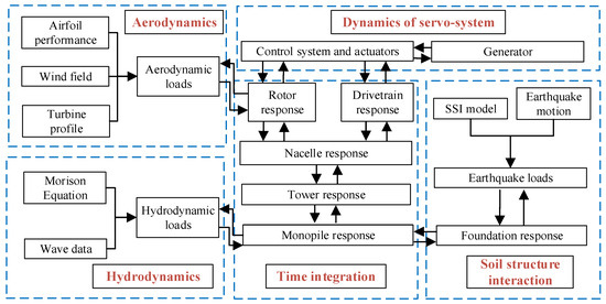
Figure 7.
Flow chart of seismic response analysis for GH-bladed code.
Table 5.
Load cases for seismic response of DTU 10 MW MOWT.
4. Results and Discussion
The directional dependence of mechanical properties in MOWTs originates from asymmetries in both the blade stiffness distribution and RNA rotational inertia, leading to differentiated dynamic characteristics along the FA and SS directions. Section 4.1 and Section 4.2 investigate the directional dependence of natural frequencies and aerodynamic damping in the 10 MW MOWT, respectively, with particular emphasis on their implications for structural integrity. Following this, Section 4.3 and Section 4.4 systematically evaluate seismic responses for both operational and parked OWTs, focusing on two critical aspects: (1) directional effects and (2) parametric sensitivities induced by asymmetries in stiffness, mass, and aerodynamic damping.
4.1. Natural Frequency of the System
Table 6 summarizes the natural frequency characteristics of the 10 MW MOWT support structure. The first two FA eigenfrequencies show good agreement with the benchmark solution [55], confirming the computational accuracy of the proposed modeling methodology. Notably, the 0.5% relative deviation between the first-order FA and SS eigenfrequencies suggests negligible directional effects arising from structural asymmetries in both the blade stiffness distribution and RNA rotational inertia at low-order modes. However, second-order modal analysis reveals significant directional divergence, with a 15% frequency disparity between the FA and SS modes. This discrepancy becomes critical under seismic excitation scenarios, as high-frequency components in ground motions can effectively excite second-order structural modes, thereby amplifying direction-dependent responses and potentially compromising structural integrity. The corresponding modes are illustrated in Figure 8.
Table 6.
Natural frequencies for the support structure of DTU 10MW MOWT.
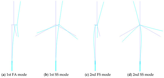
Figure 8.
First two mode shapes of the 10 MW MOWT.
Table 7 summarizes the natural frequencies of the 10 MW MOWT blade. The computational results demonstrate full agreement with the published reference data from the DTU 10 MW wind turbine report [42], showing a maximum deviation of 2.77% across all analyzed modes. The pronounced stiffness disparity between the flap-wise and edge-wise directions induces a significant frequency difference between these modes. Specifically, a 51.7% frequency differential exists between the first-order flap-wise and edge-wise modes, and this disparity increases to 59.8% for the second-order modes. Such an extreme disparity stems from the airfoil-shaped cross-sections of modern wind turbine blades, where intentional stiffness anisotropy optimizes aerodynamic efficiency while introducing pronounced vibrational directionality.
Table 7.
Natural frequencies for the blade of DTU 10MW MOWT.
4.2. Aerodynamic Damping of 10 MW MOWT
Table 8 summarizes the viscous damping coefficients of the equivalent aerodynamic dampers at the hub center for the 10 MW MOWT across operational wind speeds. Evidently, for the translational dampers, the damping coefficient in the FA direction is significantly larger than that in the SS direction. For the rotational dampers, the damping coefficient about the y-axis is notably greater than that about the x-axis.
Table 8.
Viscous damping coefficient of tower top under different wind speeds.
Figure 9 displays the aerodynamic damping ratios of the first four modes in the FA and SS directions for the 10 MW MOWT. The FA-direction damping ratios are consistently greater than their SS-direction counterparts across all the investigated modes, with their wind speed dependence patterns showing distinct directional characteristics. Quantitatively, the minimum FA/SS aerodynamic damping ratios reach 7.2, 2.9, 5.1, and 2.2 for the first to fourth modes, respectively, confirming pronounced aerodynamic damping anisotropy between the two orthogonal directions. Furthermore, the aerodynamic damping characteristics of FA and SS vibration modes demonstrate fundamentally distinct wind speed dependencies. The FA aerodynamic damping ratios reach maximum magnitudes at rated wind speed, while SS damping ratios maintain persistent monotonic growth throughout the operational wind speed range. This directional asymmetry holds practical significance as aerodynamic damping dominates in running OWTs. The observed anisotropy may significantly influence the system’s response excited by ground motions in different directions.
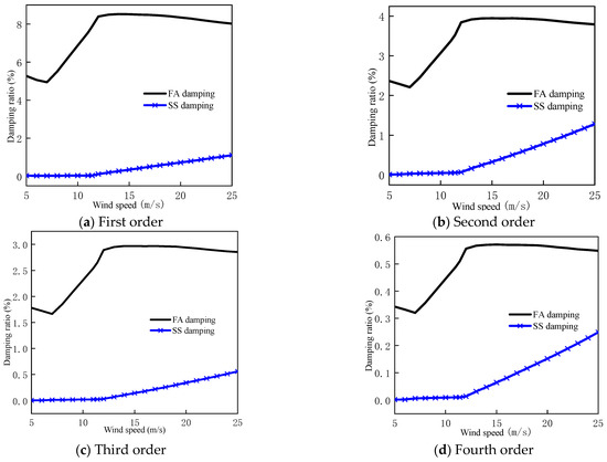
Figure 9.
First four modal aerodynamic damping ratios of DTU 10 MW MOWT.
4.3. Seismic Response of 10 MW MOWT in the Parked Condition
This section examines the seismic response of the parked MOWT under earthquake excitation, with the environmental loading components (wind, wave, and current) excluded from the analysis. The rotor blades were configured with a 90° pitch angle to simulate the parked condition. Under this operational condition, the system asymmetry principally originates from directional disparities in both the blade stiffness and RNA rotational inertia.
To systematically account for the directional dependence in seismic excitation inputs, the ground motion components listed in Table 4 were incrementally rotated about the z-axis in 15° counterclockwise increments from the positive x-axis orientation, resulting in 24 distinct excitation directions. For analytical clarity, the seismic input direction is defined through an azimuth angle (θ) measured from the positive x-axis, with counterclockwise rotation designated as the positive angular convention, as systematically documented in Table 9.
Table 9.
Relation between direction and input azimuth angle of seismic.
4.3.1. Directional Effect of Seismic Response for the Parked MOWT
The structural performance of the MOWT support structure is predominantly governed by bending failure. The excessive tower-top displacement and rotational angle may compromise the structural serviceability of the RNA, while amplified bending moments could induce critical damage to the yaw control mechanism. Accordingly, this study monitors four principal response parameters to characterize the MOWT’s dynamic response: (1) tower-top displacement (TTD), (2) tower-top rotation angle (TTR), (3) yaw-bearing bending moment (YBM), and (4) mudline bending moment (MBM).
The ground motion record 9 corresponds to a horizontal acceleration time history acquired at the Beverly Hills-Mulhol station during the 1994 Northridge earthquake (United States). Figure 10 presents the structural response time histories under the seismic excitation applied along a 45° azimuth angle relative to the global coordinate system. This configuration subjects the structure to bidirectional seismic loading along the principal axes. The structural responses along the x- and y-axes exhibit significant differences despite identical input ground motions applied to both principal directions. The most notable is the bending moment of the yaw bearing, with the peak bending moment about the x-axis reaching 2.9 MN·m and that about the y-axis reaching 13.1 MN·m. The observed response disparities between orthogonal axes (x- and y-directions) originate from the inherent structural asymmetries. These computational results validate the non-axisymmetric dynamic characteristics of the 10 MW MOWT, primarily attributable to its RNA and blade configuration.
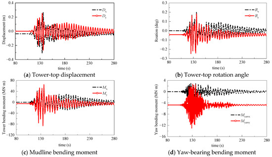
Figure 10.
Seismic response time history of parked 10 MW MOWT excited by seismic record 9 with 45° input angle.
When the seismic excitation direction is oblique to the structural principal axes (coordinate axes), the magnitude of the resultant bending moment, displacement, and rotation angle for the MOWT support structure can be determined through Equations (18)–(21):
where Dtot represents the total tower-top displacement time history, Dx(t) and Dy(t) are the tower-top displacement in the x- and y-directions; Rtot denotes the total tower-top rotation angle time history, with Rx(t) and Ry(t) being the tower-top rotation angle in the x- and y-directions; Mbtm signifies the total mudline bending moment time history, and Mx(t) and My(t) are the mudline bending moments in the x- and y-directions; Myaw corresponds to the total yaw-bearing bending moment time history, with Myawx(t) and Myawy(t) representing the yaw-bearing bending moments in the x- and y-directions.
Figure 11 depicts the extreme-value responses (maximum and minimum peaks) of the four structural parameters under the excitation of seismic record 9, with the numbers after Dir. in the legend representing the direction of the extremum. The TTD exhibits maximum and minimum peak values of 0.44 m (direction 13) and 0.38 m (direction 20), respectively, yielding a peak-to-peak variation of 15.7%. The TTR demonstrates extremes of 0.35° (direction 13) and 0.28° (direction 20), corresponding to a relative variation of 23.3%. The MBM manifests peak magnitudes of 118.2 MN·m (direction 1) and 97.8 MN·m (direction 18), showing a 20.9% differential. The YBM reaches critical values of 15.8 MN·m (direction 1) and 9.4 MN·m (direction 7), revealing a substantial disparity of 68.5%. These directional response extremes, all exceeding the 10% variation threshold under multidirectional excitation of seismic record 9, validate significant azimuth-dependent characteristics in the seismic response of the 10 MW MOWT.
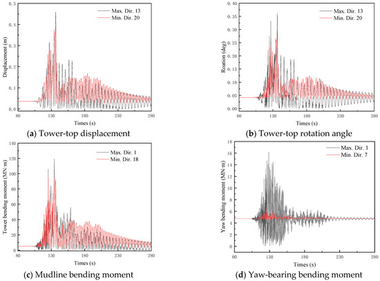
Figure 11.
Seismic response time history of parked 10 MW MOWT excited by seismic record 9.
The azimuth-dependent variations in peak dynamic response amplitudes of the MOWT subjected to the seismic records 9, 11, and 13 are presented in Figure 12. To quantify this directional dependence, the total directional effect coefficient (δE) is formulated in Equation (22):
where is the maximum peak structural response when ground motions are input along different directions, while is the minimum peak structural response under varying seismic input directions.
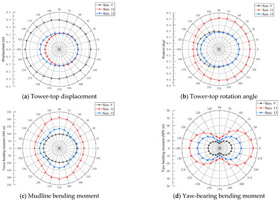
Figure 12.
Seismic response magnitude of parked 10 MW MOWT.
Table 10 summarizes the total directional effect coefficients and critical directions associated with the seismic records 9, 11, and 13. It is evidenced that the maximum structural response metrics predominantly occur when seismic excitation aligns with either the SS or FA directions of the OWT. However, two critical directional phenomena are identified. First, the most critical directions for equivalent response metrics exhibit substantial variation across different ground motion records. For instance, the TTR attains its maximum value under FA-direction excitation (0°) for seismic record 9, whereas it peaks under SS-direction excitation (270°) for seismic record 11. Second, within a single earthquake event, distinct response parameters are governed by different critical orientations. A representative case is a seismic record 11, where the peak TTD occurs under FA-direction excitation (0°), whereas the maximum TTR is observed under SS-direction excitation (270°).
Table 10.
Total directional effect coefficient and most critical direction of seismic record 9, 11, and 13 for parked 10 MW MOWT.
All the seismic records listed in Table 4 were applied to investigate the dynamic response of the 10 MW MOWT. As the input ground motions comprise unidirectional horizontal seismic records without additional supplementary lateral loads, the critical directions of the input ground motion consistently coincide with either the FA (0°/180°) or SS (90°/270°) direction of the OWT. This is similar to the analysis results on the seismic response of NREL 5 MW wind turbine [39]. However, due to the asymmetric characteristics of these ground motion records, the critical seismic input azimuths may correspond to either 0° or 180° for the FA direction, and 90° or 270° for the SS direction.
Figure 13 presents the total directional effect coefficients for the four aforementioned response parameters. The analysis identified distinct directional-dependence patterns. For the TTD, 10 records exhibit total directional effect coefficients exceeding 10%, with a maximum value of 24%. For the TTR, 13 records demonstrate total directional effect coefficients above 10%, peaking at 28%. For the MBM, eight records show total directional effect coefficients surpassing 10%, reaching a maximum of 21%. For the YBM, all ground motions produce total directional effect coefficients exceeding 30%, with the maximum value reaching 73%, significantly higher than those of the other three parameters. These results confirm the prevalence of directional dependence in seismic responses for large-capacity MOWTs under the parked condition, with the most critical directions being ground motion-specific and response parameter-dependent.
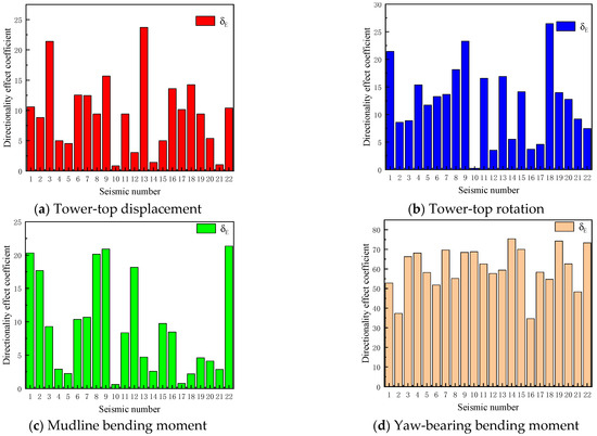
Figure 13.
Total directional effect coefficient of all ground motions for parked 10 MW MOWT.
4.3.2. Parametric Study on Seismic Response Directionality for Parked MOWT
For the parked OWT with an axisymmetric support structure, the directional dependence in seismic responses under unidirectional horizontal seismic excitations originates from two anisotropic mechanisms: (1) blade stiffness anisotropy in the flap-wise/edge-wise directions, and (2) directional variability of the RNA rotational inertia. In the preceding analysis (Section 4.3.1), the combined effects of these mechanisms were evaluated to determine the total directionality effects. Quantifying their individual contributions is essential for developing simplified seismic response models for OWTs.
To investigate the individual effects, this study employs a parameter homogenization approach. The flap-wise and edge-wise stiffness of the blade are averaged to eliminate blade stiffness anisotropy, while preserving all other structural parameters. Subsequently, all the ground motion records from Table 4 are applied along predefined orientations (directions 1~24) to analyze the seismic responses of the 10 MW MOWT. Notably, the current analytical framework preserves only the directional differences in RNA rotational inertia between the FA and SS directions, thereby specifically isolating the inertial-induced directional dependence effects.
Figure 14 displays the time–history curves of maximum and minimum peak values for the four aforementioned seismic response parameters under seismic record 9. The directional-dependence analysis reveals the following observations: the TTD exhibits maximum and minimum peaks at directions 13 and 20, respectively, with a relative difference of 16.5%. For the TTR, the extreme values occur at directions 13 (maximum) and 5 (minimum), showing a 19.8% relative variation. The MBM of the support structure demonstrates a 12.4% disparity between its maximum at direction 1 and minimum at direction 17. Notably, the YBM displays the most significant directional sensitivity, with a 67.1% relative difference between maximum (direction 1) and minimum (direction 7) peaks. The comparative evaluation with previous results incorporating both RNA rotational inertia and blade stiffness anisotropy indicates that while the critical excitation orientations remain unchanged, the relative differences between extreme response values exhibit parameter-dependent characteristics.
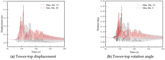
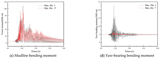
Figure 14.
Seismic response time history of parked 10 MW MOWT excluding blade stiffness anisotropy.
To quantitatively investigate the influence of the blade stiffness and RNA inertia anisotropy, the RNA inertia directional effect coefficient () is given by Equation (23):
where represents structural response peak considering exclusively RNA rotational inertia anisotropy; represents the corresponding minimum value. When the input ground motions are seismic records 9, 11, and 13, the variation in OWT response peaks with seismic azimuth angles is illustrated in Figure 15. The directional effect coefficients of RNA inertia and the most critical direction are summarized in Table 11. Figure 12 and Figure 15 demonstrate that the 0° or 180°orientations constitute the most critical direction governing the peak YBM under seismic record 11. The 0° orientation emerges when considering coupled anisotropic effects (RNA inertia and blade stiffness simultaneously), whereas 180° becomes dominant under conditions of isolated RNA inertial anisotropy. Both critical directions exhibit alignment with the FA axis of the MOWT. For scenarios involving solely RNA inertial anisotropy, the YBM registers 21 MN·m at 0° versus 22.5 MN·m at 180°, demonstrating a marginal variation of 7%. Notably, consistent critical directions are observed in both models when subjected to excitation of seismic records 9 and 13. Given that the models differ exclusively in the blade stiffness anisotropy representation, these comparative results suggest that the blade stiffness anisotropy exerts negligible influence on the most critical direction determination for the investigated structural parameters under seismic records 9, 11, and 13.
Figure 15.
Seismic response magnitude of parked 10 MW MOWT excluding blade stiffness anisotropy.
Table 11.
Directional effect coefficient and most critical direction of seismic response parked 10 MW MOWT excluding blade stiffness anisotropy.
As indicated in Table 10 and Table 11, significant discrepancies exist between the total directional effect coefficient and the directional effect coefficient of RNA inertia, particularly for TBM, which demonstrates the most pronounced variation. To quantitatively compare the impacts of these two directional effect factors, the blade stiffness directional effect coefficient () is expressed through Equation (24):
Figure 16 compares the total directional effect coefficients (), the directional effect coefficients of RNA inertia (), and the directional effect coefficients of blade stiffness () under seismic records 9, 11, and 13. The results demonstrate that the RNA inertia anisotropy predominantly influences the directional dependence of the system’s response compared with the blade stiffness anisotropy across the three ground motions. Specifically, the RNA inertia anisotropy governs the peak responses of TTD and YBM. For the TTR, while RNA inertia anisotropy remains dominant, neglecting the blade stiffness anisotropy may introduce significant errors. In contrast, the blade stiffness anisotropy exhibits comparable influence to the RNA inertia anisotropy on the MBM peaks under specific ground motions (e.g., seismic records 9 and 13), necessitating concurrent consideration of both factors. These observations indicate that the relative contributions of RNA inertia and blade stiffness anisotropies depend on both the ground motion properties and structural response parameters, with neither factor universally dominant. The non-negligible role of blade stiffness anisotropy aligns with findings reported in prior studies [55].
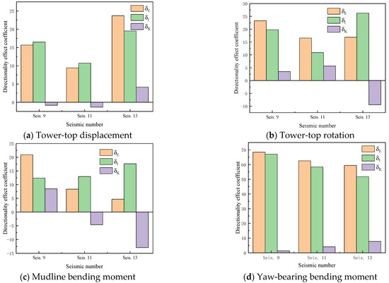
Figure 16.
Directional effect coefficient of 10 MW MOWT induced by different mechanisms for seismic records 9, 11, and 13.
Figure 17 compares the total directional effect coefficients, directional effect coefficients of RNA inertia, and directional effect coefficients of blade stiffness for the aforementioned four parameters under the excitation of seismic records in Table 4. On the whole, under the parked condition, the total directional effects cannot be neglected for the selected ground motions. For the peak TTD, the seismic record 13 exhibits the most significant directional influence, with a total directional effect coefficient of 24%. For the peak TTR, the seismic record 18 demonstrates the strongest directional dependence, yielding a total directional effect coefficient of 28%. For the peak MBM, the seismic record 9 shows the most pronounced directional effect, with a total directional effect coefficient of 21%. For the peak YBM, the seismic record 14 displays the highest directional sensitivity, achieving a total directional effect coefficient of 73%. Notably, the directional effect for the yaw-bearing bending moment is substantially more prominent than those of the other three parameters. The asymmetry in the MOWT originates from the RNA rotational inertia and blade stiffness, both located near the yaw mechanism. This configuration amplifies the directional dependence of the yaw-bearing bending moment for 10 MW MOWT. Compared to existing research [38,39,40,41], this phenomenon is first identified in this study. Given that the yaw mechanism is a weak component in wind turbines, the industry should pay close attention to this issue.
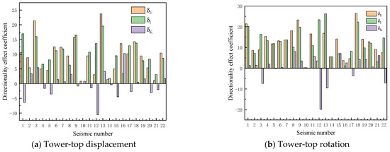
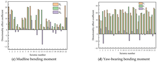
Figure 17.
Directional effect coefficient of 10 MW MOWT induced by different mechanisms for all seismic records.
Table 4 incorporates strong ground motion records with distinct characteristics, such as near-field, far-field, and pulse-type motions, ensuring that the results in Figure 17 encompass diverse seismic scenarios. For the peak TTD and TTR, the RNA inertia anisotropy is the dominant factor across most ground motion records. However, in specific instances (e.g., seismic record 16), the blade stiffness anisotropy has a greater influence than the RNA inertia anisotropy. For the peak MBM, the trend is similar to the tower-top responses, but the influence of the blade stiffness anisotropy exceeds that of the RNA inertia anisotropy in several ground motions (e.g., seismic record 1, 16, and 22). For the peak YBM, the blade stiffness anisotropy never surpasses the RNA inertia anisotropy. In contrast, for the peak YBM, the blade stiffness anisotropy consistently exhibits lower influence than the RNA inertial anisotropy throughout all analyzed seismic records.
This section aims to identify the predominant contributor to directional dependence in seismic responses of parked MOWTs. The results show that there is no consistent dominance pattern between the two anisotropic mechanisms (RNA rotational inertia versus blade stiffness) across varying structural response parameters and ground motions. These findings collectively suggest that comprehensive seismic analysis of MOWTs must explicitly account for both the RNA rotational inertia anisotropy and blade stiffness anisotropy in structural modeling.
4.4. Seismic Response of 10 MW MOWT in the Running Condition
The IEC and GL standards recommend that combined wind–wave and seismic loads should be considered in the seismic response analysis of OWTs [4,46]. The modern OWTs widely employ pitch control systems, where aerodynamic forces reach their maximum under the running condition when the hub-height mean wind speed matches the rated wind speed [37]. Accordingly, the hub-height mean wind speed in this study was set to 11.4 m/s, with its time history illustrated in Figure 18. Combined with the wave model described in Section 3, the dynamic structural response of the MOWT under wind–wave loads is presented in Figure 19. For TTD, TTR, and MBM, the peak values along/about the x-axis are significantly greater than those about/along the y-axis; however, for YBM, the peak value about the x-axis is 10.5 MN·m, while that about the y-axis is 12.1 MN·m.
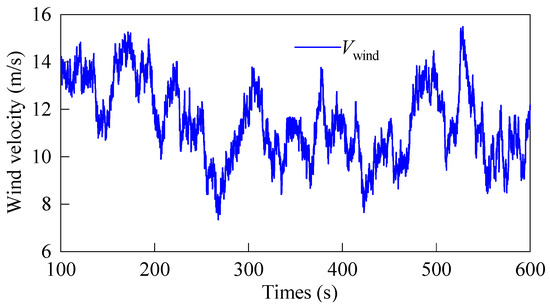
Figure 18.
Time history of hub-height wind velocity in x-axis.
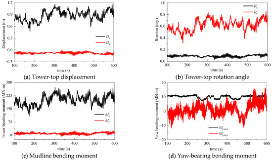
Figure 19.
Dynamic response time history of 10 MW MOWT excited by wind and wave.
4.4.1. Directional Effect of Seismic Response for the Running MOWT
The dynamic response of the 10 MW MOWT under a combined wind–wave-seismic loading was analyzed using the wind and wave load models described in Section 4.1. In the numerical simulations, the wind and wave loads were held in fixed directions, while strong ground motions were applied along 24 distinct directions (directions 1 to 24).
Figure 20 shows the time histories of the maximum and minimum peaks for the four aforementioned parameters under seismic record 9 excitation. For the TTD, the peaks reach their maximum and minimum values when the ground motion is input along directions 15 and 17, respectively, with a relative difference of 8.3%. For the TTR, the maximum and minimum peaks occur under directions 16 and 17, respectively, showing a relative difference of 3.6%. For the MBM, the peaks vary most significantly between directions 19 and 17, yielding a relative difference of 7.1%. For the YBM, the largest relative difference (13.1%) is observed between directions 14 and 24. Compared with the parked condition, the directional effects on the seismic response of the 10 MW MOWT under seismic record 9 are significantly reduced, with the maximum relative difference among the four parameters slightly exceeding 13%.
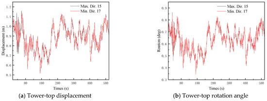
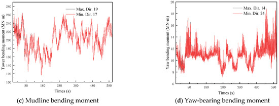
Figure 20.
Dynamic response time history of running MOWT excited by wind, wave, and seismic record 9.
Figure 21 illustrates the variation in peak responses of the MOWT with seismic input azimuth angles under the excitation from seismic records 9, 11, and 13. Table 12 summarizes the total directional effect coefficients and the most critical input direction for these ground motions. As shown in Figure 21 and Table 12, the most critical input directions differ across ground motions for the identical response parameter. For example, the most critical input direction for the tower-top rotation angle is 225 degrees under seismic record 9 but shifts to 180 degrees under seismic record 13. Similarly, for a single ground motion, the most critical input direction varies across different response parameters.
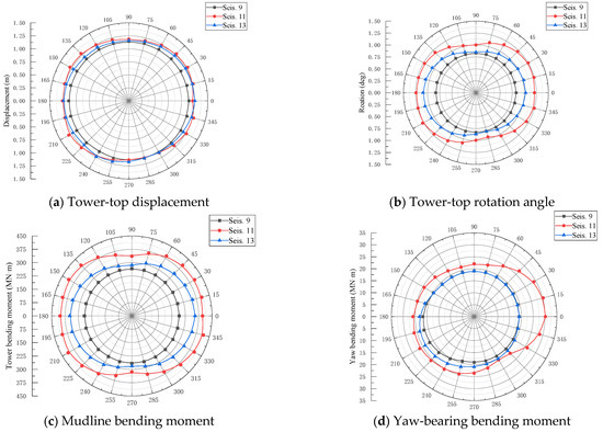
Figure 21.
Seismic response magnitude of running 10 MW MOWT.
Table 12.
Total directional effect coefficient and most critical direction of seismic record 9, 11, and 13 for running 10 MW MOWT.
Compared with the parked condition, the running condition exhibits significant differences in the most critical input directions for the selected structural response parameters, which is similar to the conclusions on NREL 5 MW MOWT [41]. This is attributed to wind loads acting in both horizontal orthogonal directions, which prevent the critical input directions from aligning purely with the FA or SS directions of the turbine. Quantitatively, the total directional effect coefficient for the peak YBM decreases significantly in the running condition, while coefficients for other parameters show mixed trends (both increases and decreases) without a unified pattern. On the whole, the total directional effects under the running condition are more complex than those under the parked condition. When the seismic load is combined with wind–wave loads, the maximum peaks of the four parameters occur at different input directions. Based on these three case studies, the seismic response of running MOWTs depends on two governing factors: (1) seismic excitation azimuth and (2) ground motion characteristics.
Figure 22 shows the total directional effect coefficients for the four aforementioned parameters. Specifically, for the TTD, 12 cases exceed 10%, with a maximum of 28%. For the TTR, 17 cases excess 10%, reaching a maximum of 28%. For the MBM, 18 cases exceed 10%, with a maximum of 23%. For the YBM, 12 cases exceed 10%, peaking at 38%. Compared with the parked condition, the running condition results in more complex critical input directions for seismic responses of the OWT. The total directional effect coefficients for peak TTD, TTR, and MBM are notably larger under the running condition than the parked condition. Thus, the total directional effects of seismic excitation on the 10 MW MOWT are more pronounced during the running condition.
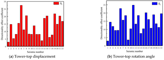
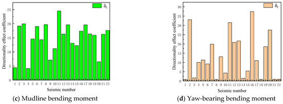
Figure 22.
Total directional effect coefficients of seismic response for running 10 MW MOWT.
4.4.2. Parametric Study on Seismic Response Directionality for Running MOWT
Under the running condition, the seismic response of the MOWT results from combined wind, wave, and seismic excitations. Additionally, the aerodynamic damping induced by aero-elastic effects influences the system. As shown in Figure 9, the aerodynamic damping of the 10 MW MOWT exhibits significant directional dependence. Consequently, the directional effects on the seismic responses of the MOWT under the running condition result from the coupling of wind–wave loads, aerodynamic damping, and structural asymmetry. In earthquake engineering, directional effects under combined environmental and seismic loads have been extensively studied, as referenced in prior works [56,57].
This subsection first investigates the influence of aerodynamic damping on the directional effects of the 10 MW MOWT’s seismic response. The wind–wave loads are excluded, and the aerodynamic damping is incorporated into the tower’s relevant modes as modal aerodynamic damping ratios (see Figure 9). Using the ground motions listed in Table 4, the directional effects of the system’s seismic response are analyzed. Notably, three inherent system properties—blade stiffness, rotor-nacelle assembly (RNA) inertia, and aerodynamic damping—collectively govern the directional dependence of the dynamic response.
Figure 23 presents the time histories of the maximum and minimum peaks for the four aforementioned parameters under seismic record 9 excitation. Compared with the parked condition, the consideration of aerodynamic damping leads to significant reductions in both maximum and minimum peaks of these parameters. The maximum TTD occurs when the seismic input is oriented along direction 7, while its minimum value appears under direction 13, exhibiting a relative difference of 34.1%. For the TTR, the peak values under directions 18 (maximum) and 13 (minimum) demonstrate an 18.8% relative discrepancy. Regarding the MBM, directions 5 (maximum) and 13 (minimum) correspond to a 17.8% difference. Notably, the YBM shows the largest variation (62.3%) between directions 1 (maximum) and 19 (minimum). The comparative analysis with Figure 23 reveals that considering only these three inherent characteristics would overestimate the influence of seismic input directions.
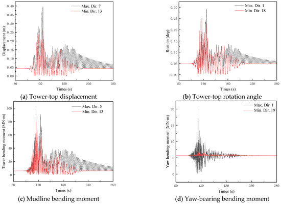
Figure 23.
Seismic response time history of running 10 MW MOWT excluding wind–wave loads.
Figure 24 illustrates the variation in peak responses for the MOWT with seismic azimuth angles under the excitation of seismic records 9, 11, and 13. To quantitatively investigate the directional effects of the three aforementioned inherent system characteristics on seismic responses, the system inherent characteristic coefficient () is defined as follows in Equation (25):
where denotes the maximum structural response peak considering only the anisotropy of system inherent characteristics, represents the corresponding minimum value. Table 13 lists the directional effect coefficient of the system’s inherent characteristics and the most critical directions for the system excited by seismic records 9, 11, and 13. Compared with Table 12, both the most critical directions and directional effect coefficients exhibit significant differences.
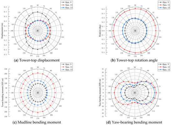
Figure 24.
Seismic response magnitude of running 10 MW MOWT excluding wind–wave loads.
Table 13.
Directional effect coefficient and most critical direction of running 10 MW MOWT excluding wind–wave loads.
Under the running condition, the seismic response of MOWTs requires the combination of seismic excitation with wind–wave load. As the input ground motion direction varies, the combination coefficients and methods of these two load effects also change. To quantify the directional effect induced by load combination, the load combination directional effect coefficient () is modeled by Equation (26):
Figure 25 compares the total directional effect coefficient, the directional effect coefficient of the system’s inherent characteristic (), and directional effect coefficient of load combination () of the MOWT excited by the seismic records 9, 11, and 13. For the ground motion 9, both factors exhibit comparable magnitudes of influence but demonstrate opposing contributions. Similar patterns are observed for the seismic records 11 and 13. Consequently, the analysis of seismic directional effects on MOWTs necessitates simultaneous consideration of these two factors.
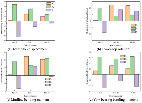
Figure 25.
Directional effect coefficient of running 10 MW MOWT induced by different mechanisms for seismic records 9, 11, and 13.
Figure 26 compares the total directional effect coefficient (), directional effect coefficient of system inherent characteristic (), and directional effect coefficient of load combination () for peak values of the four aforementioned parameters. On the whole, the total directional effects of the running MOWT cannot be neglected for the selected ground motions. The input direction of ground motion 6 exhibits the most significant influence on the peak TTD, yielding a total directional effect coefficient of 28%. For the peak TTR, the ground motion 11 shows the strongest directional influence with a of 25%. Similarly, the ground motion 11 dominates the peak MBM with a of 23%, while a seismic record 16 induces the largest (38%) for the peak YBM. Compared with the parked MOWT, the total directional effect coefficients for the yaw-bearing bending moment generally decrease, which is associated with the aerodynamic damping effect of the OWT under the running condition.
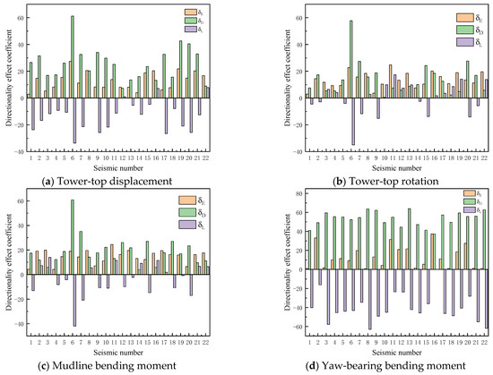
Figure 26.
Directional effect coefficient of running 10 MW MOWT induced by different mechanisms for all seismic records.
The strong ground motion records selected in Table 4 encompass rich spectral content, resulting in the complex and multi-scenario outcomes presented in Figure 26. For the tower-top displacement, the anisotropy of the system’s inherent characteristics predominantly outweighs the load combination directional effect. However, comparable magnitudes between these two effects occur under specific ground motions (e.g., seismic record 1, 17, and 20). Regarding the tower-top rotation angle, the inherent characteristic anisotropy of the system generally dominates across most ground motions, though reversed influence patterns emerge under particular cases (e.g., seismic records 11, 13, and 19). The mudline bending moment exhibits analogous patterns to tower-top rotations, thus, not requiring redundant elaboration. The most distinctive feature of the yaw-bearing bending moments lies in the opposing signs between directional effect coefficients induced by the two factors. In such scenarios, isolated consideration of either factor may yield trend-distorted conclusions.
This section categorizes the directional effects on the seismic responses of running MOWTs into two factors: system inherent characteristic anisotropy and load combination directional effects. The numerical examples demonstrate significant variations in the relative influence of these two factors across different structural response parameters and input ground motions. The existing earthquake engineering studies have systematically investigated load combinations of environmental and seismic actions, providing valuable insights for offshore wind turbine design. Building on this foundation, this analysis demonstrates that accurate seismic predictions for MOWTs require dynamic models to explicitly account for directional effects in three key aspects: blade stiffness, RNA rotational inertia, and aerodynamic damping.
5. Conclusions and Outlook
The monopile-supported offshore wind turbine (MOWT) is a dynamically coupled system integrating the rotor-nacelle assembly (RNA) and its support structure. Although the monopile exhibits axisymmetric geometry, directional-dependent variations in stiffness, inertia, and damping properties of the wind turbine result in anisotropic dynamic characteristics. While existing studies [38,39] have predominantly focused on the directional effects of seismic response for 5 MW OWTs, this paper investigates the dynamic behavior of a 10 MW MOWT at a representative marine site, with particular emphasis on identifying the mechanisms of seismic directional effects. The investigation yields the following critical findings specific to this 10 MW MOWT:
1. While the monopile is geometric symmetry, the wind turbine exhibits pronounced anisotropic characteristics in inertia and stiffness, leading to directional dependence of natural frequencies for both blades and the support structure. Specifically, the DTU 10 MW reference turbine’s RNA shows an over 60% difference in rotational inertia between principal axes, while blade flap-wise and edge-wise stiffness exhibit a 30% average variation. Remarkably, the tower’s fore–aft (FA) and side–side (SS) second-mode frequencies differ by 15%, whereas the first two flap-wise/edge-wise blade frequencies display over 50% disparity.
2. The DTU 10 MW MOWT exhibits differences in aerodynamic behavior and natural frequencies between the FA and SS directions, resulting in significant directional effects on aerodynamic damping. Numerical case studies reveal that for this 10 MW MOWT, the viscous damping coefficient of the tower-top aerodynamic damper corresponding to FA vibrations is significantly higher than that in the SS direction. During operational wind speeds (cut-in to cut-out), first-order modal aerodynamic damping ratios reach 5–8% in the FA direction, compared with only 0.3–1% in the SS direction.
3. The directional effects of seismic responses for the parked DTU 10 MW MOWT are determined by the anisotropy in RNA rotational inertia and blade stiffness in different principal axes. The case studies reveal that seismic input direction significantly influences the dynamic responses of this MOWT during the parked condition. The maximum directionality coefficients reach 24%, 28%, 21%, and 73% for peak tower-top displacement, tower-top rotation, mudline bending moment, and yaw-bearing moment, respectively. Notably, the critical seismic input directions vary both among different ground motions for identical response parameters and between various parameters under the same excitation.
4. The seismic directional effects of the running DTU 10 MW MOWTs originate from inherent system anisotropy (rotor inertia, structural stiffness, aerodynamic damping) combined with environmental loads (wind, waves). The analyses reveal that seismic input direction critically influences the dynamic response of this running MOWT. The maximum total directional effect coefficients reach 28% for tower-top displacement, 25% for tower-top rotation, 23% for mudline bending moment, and 38% for yaw-bearing bending moment. Compared with the parked condition, the running condition amplifies directional effects for peak tower-top displacement, rotation, and mudline bending moment.
The research conducted in this study was specific to a particular turbine model; therefore, the conclusions drawn here are only applicable to the DTU 10 MW MOWT until further investigations are extended to other OWTs. In this study, only unidirectional horizontal seismic inputs were considered. Additionally, while asymmetric support structures (e.g., jacket-type foundations) have been widely adopted in industrial applications, and prior research [40] has highlighted the influence of seismic input directions on such structures, this work focused solely on the monopile substructure. To address these research limitations, future studies should incorporate bidirectional horizontal seismic inputs and examine asymmetric support structures. Furthermore, developing efficient methods to identify the most unfavorable seismic input directions should be prioritized in subsequent research.
Author Contributions
Conceptualization, R.X. and W.Y.; methodology, R.X. and Y.L.; software, Y.L.; validation, R.X. and Q.Z.; formal analysis, R.X. and Q.Z.; investigation, R.X. and W.Y.; resources, R.X. and Y.L.; data curation, R.X., Q.Z. and W.Y.; writing—original draft preparation, R.X. and Q.Z.; writing—review and editing, R.X., Q.Z. and Y.L.; visualization, R.X. and Q.Z.; supervision, R.X. and Y.L.; project administration, R.X. and Y.L.; funding acquisition, R.X. and Y.L. All authors have read and agreed to the published version of the manuscript.
Funding
This research is jointly funded by the National Natural Science Foundation of China (Grant No.: 52278480 and 52301343), the Natural Science Foundation of Zhejiang Province (Grant No.: LQ23E090003), and the “Leading Goose” R&D Program of Zhejiang (Grant No.: 2023C03122).
Data Availability Statement
No new data were created or analyzed in this study. Data sharing is not applicable to this article.
Conflicts of Interest
Author Yongqing Lai was employed by the company PowerChina Huadong Engineering Corporation Limited. The remaining authors declare that the research was conducted in the absence of any commercial or financial relationships that could be construed as a potential conflict of interest.
References
- BP. Energy Outlook [EB]; BP, 2023. Available online: https://www.bp.com/en/global/corporate/energy-economics/energy-outlook.html (accessed on 1 April 2025).
- Global Wind Energy Council GWEC. Global Wind Report Annual Market Update 2024; Global Wind Energy Council GWEC, 2024. Available online: https://www.gwec.net/reports/globalwindreport (accessed on 1 April 2025).
- Bhattacharya, S.; Biswal, S.; Aleem, M.; Amani, S.; Prabhakaran, A.; Prakhya, G.; Lombardi, D.; Mistry, H.K. Seismic Design of Offshore Wind Turbines: Good, Bad and Unknowns. Energy 2021, 14, 3496. [Google Scholar] [CrossRef]
- DNV RP 0585. Seismic Design of Wind Power Plants. DET NORSKE VERITAS, 2021. Available online: https://www.dnv.com/energy/standards-guidelines/dnv-rp-0585-seismic-design-of-wind-power-plants/ (accessed on 1 April 2025).
- Zheng, X.Y.; Li, H.; Rong, W.; Li, W. Joint Earthquake and Wave Action on the Monopile Wind Turbine Foundation: An Experimental Study. Mar. Struct. 2015, 44, 125–141. [Google Scholar] [CrossRef]
- Santangelo, F.; Failla, G.; Arena, F.; Ruzzo, C. On Time-Domain Uncoupled Analyses for Offshore Wind Turbines under Seismic Loads. Bull. Earthq. Eng. 2018, 16, 1007–1040. [Google Scholar] [CrossRef]
- Bhattacharya, S.; De Risi, R.; Lombardi, D.; Ali, A.; Demirci, H.E.; Haldar, S. On the Seismic Analysis and Design of Offshore Wind Turbines. Soil. Dyn. Earthq. Eng. 2021, 145, 106692. [Google Scholar] [CrossRef]
- Hacıefendioğlu, K.; Bayraktar, A. Effect of Ice Sheet on Stochastic Response of Offshore Wind Turbine–Seawater–Soil Interaction Systems Subjected to Random Seismic Excitation. J. Cold Reg. Eng. 2011, 25, 115–132. [Google Scholar] [CrossRef]
- Anastasopoulos, I.; Theofilou, M. Hybrid Foundation for Offshore Wind Turbines: Environmental and Seismic Loading. Soil Dyn. Earthq. Eng. 2016, 80, 192–209. [Google Scholar] [CrossRef]
- Bargi, K.; Dezvareh, R.; Mousavi, S.A. Contribution of Tuned Liquid Column Gas Dampers to the Performance of Offshore Wind Turbines under Wind, Wave, and Seismic Excitations. Earthq. Eng. Eng. Vib. 2016, 15, 551–561. [Google Scholar] [CrossRef]
- Wang, W.; Gao, Z.; Li, X.; Moan, T. Model Test and Numerical Analysis of a Multi-Pile Offshore Wind Turbine Under Seismic, Wind, Wave, and Current Loads. J. Offshore Mech. Arct. Eng. 2017, 139, 031901. [Google Scholar] [CrossRef]
- Huang, Y.; Zhao, M.; Wang, P.; Cheng, X.; Du, X. Analytical Solution of Dynamic Responses of Offshore Wind Turbine Supported by Monopile under Combined Earthquake, Wave and Wind. Ocean Eng. 2023, 267, 113319. [Google Scholar] [CrossRef]
- Bozyigit, B.; Bozyigit, I.; Prendergast, L.J. Analytical Approach for Seismic Analysis of Onshore Wind Turbines Considering Soil-Structure Interaction. Structures 2023, 51, 226–241. [Google Scholar] [CrossRef]
- Kourkoulis, R.S.; Lekkakis, P.C.; Gelagoti, F.M.; Kaynia, A.M. Suction Caisson Foundations for Offshore Wind Turbines Subjected to Wave and Earthquake Loading: Effect of Soil–Foundation Interface. Géotechnique 2014, 64, 171–185. [Google Scholar] [CrossRef]
- Ding, H.; Xiong, K.; Zhang, P. Seismic Response of Offshore Wind Structure Supported by Bucket Foundation. Trans. Tianjin Univ. 2016, 22, 294–301. [Google Scholar] [CrossRef]
- Zayed, M.; Kim, K.; Prabhakaran, A.; Elgamal, A. Shake Table Testing and Computational Framework for Seismic Response of Utility-Scale Bucket Foundation Offshore Wind Turbines. Soil Dyn. Earthq. Eng. 2023, 171, 107939. [Google Scholar] [CrossRef]
- Xu, Y.; Shen, T.; Zuo, J.; Bhattacharya, S.; Han, Q. Shaking Table Tests and Numerical Analysis of Monopile-Supported Offshore Wind Turbines Under Combined Wind, Wave and Seismic Loads. Soil Dyn. Earthq. Eng. 2024, 183, 108793. [Google Scholar] [CrossRef]
- Sahraeian, S.M.S.; Masoumi, M.A.; Najafgholipour, M.A.; Shafiee, A.; Pandey, B. Seismic Response of Monopile Foundation of Offshore Wind Turbines Under Near-Field and Far-Field Ground Motions. Soil Dyn. Earthq. Eng. 2023, 174, 108166. [Google Scholar] [CrossRef]
- Ngo, D.-V.; Kim, D.-H. Seismic Responses of Different Types of Offshore Wind Turbine Support Structures. Ocean Eng. 2024, 297, 117108. [Google Scholar] [CrossRef]
- Kim, D.H.; Lee, S.G.; Lee, I.K. Seismic Fragility Analysis of 5 MW Offshore Wind Turbine. Renew. Energy 2014, 65, 250–256. [Google Scholar] [CrossRef]
- Mardfekri, M.; Gardoni, P. Probabilistic Demand Models and Fragility Estimates for Offshore Wind Turbine Support Structures. Eng. Struct. 2013, 52, 478–487. [Google Scholar] [CrossRef]
- Mardfekri, M.; Gardoni, P. Multi-hazard Reliability Assessment of Offshore Wind Turbines. Wind Energy 2015, 18, 1433–1450. [Google Scholar] [CrossRef]
- Yan, Y.; Li, C.; Li, Z. Buckling Analysis of a 10 MW Offshore Wind Turbine Subjected to Wind-Wave-Earthquake Loadings. Ocean Eng. 2021, 236, 109452. [Google Scholar] [CrossRef]
- Jiang, W.; Lin, C. Lateral Responses of Monopile-Supported Offshore Wind Turbines in Sands Under Combined Effects of Scour and Earthquakes. Soil Dyn. Earthq. Eng. 2022, 155, 107193. [Google Scholar] [CrossRef]
- Zhang, T.; Wang, W.; Li, X.; Wang, B. Vibration Mitigation in Offshore Wind Turbine Under Combined Wind-Wave-Earthquake Loads Using the Tuned Mass Damper Inerter. Renew. Energy 2023, 216, 119050. [Google Scholar] [CrossRef]
- Wang, P.-G.; Bai, Y.; Wang, M.; Zhao, M.; Du, X.-L. Seismic Vulnerability and Performance-Based Assessment of Monopile Offshore Wind Turbine Considering Turbine Blades. Soil Dyn. Earthq. Eng. 2024, 186, 108918. [Google Scholar] [CrossRef]
- Huang, H.S. Simulations of 10MW Wind Turbine under Seismic Loadings. Compos. Struct. 2022, 279, 114686. [Google Scholar] [CrossRef]
- Lu, Y.; Xie, W.; Wang, Y.; Liang, H.; He, Y.; Chen, X.; Yuan, J.; Zhang, Z. Dynamic Analysis of MTMD Vibration Reduction for Offshore Wind Turbine Under Combined Wind-Wave-Seismic Loads. Structures 2025, 72, 108207. [Google Scholar] [CrossRef]
- Penzien, J.; Watabe, M. Characteristics of 3-Dimensional Earthquake Ground Motions. Earthq. Eng. Struct. Dyn. 1974, 3, 365–373. [Google Scholar] [CrossRef]
- Rigato, A.B.; Medina, R.A. Influence of Angle of Incidence on Seismic Demands for Inelastic Single-Storey Structures Subjected to Bi-Directional Ground Motions. Eng. Struct. 2007, 29, 2593–2601. [Google Scholar] [CrossRef]
- Soltanieh, S.; Memarpour, M.M.; Kilanehei, F. Performance Assessment of Bridge-Soil-Foundation System with Irregular Configuration Considering Ground Motion Directionality Effects. Soil Dyn. Earthq. Eng. 2019, 118, 19–34. [Google Scholar] [CrossRef]
- Arany, L.; Bhattacharya, S.; Adhikari, S.; Hogan, S.J.; Macdonald, J.H.G. An Analytical Model to Predict the Natural Frequency of Offshore Wind Turbines on Three-Spring Flexible Foundations Using Two Different Beam Models. Soil Dyn. Earthq. Eng. 2015, 74, 40–45. [Google Scholar] [CrossRef]
- Koukoura, C.; Natarajan, A.; Vesth, A. Identification of Support Structure Damping of a Full Scale Offshore Wind Turbine in Normal Operation. Renew. Energy 2015, 81, 882–895. [Google Scholar] [CrossRef]
- Alati, N.; Failla, G.; Arena, F. Seismic Analysis of Offshore Wind Turbines on Bottom-Fixed Support Structures. Philos. Trans. R. Soc. A Math. Phys. Eng. Sci. 2015, 373, 20140086. [Google Scholar] [CrossRef]
- Wang, L.; Dong, X.T. Influence of Earthquake Directions on Wind Turbine Tower under Seismic Action. Adv. Mater. Res. 2011, 243–249, 3883–3888. [Google Scholar] [CrossRef]
- Dai Kaoshan, M.Z.; Zhi, Z. Shaking Table Test Study on Seismic Responses of a Wind Turbine under Ground Motions with Different Spectral Characteristics. Adv. Eng. Sci. 2018, 50, 125–133. [Google Scholar]
- XI, R.; XU, C.; DU, X.; XU, K. Effects of Operating Conditions on the Seismic Response of Wind Turbines. Eng. Mech. 2019, 36, 80–88. [Google Scholar]
- Yang, Y.; Ye, K.; Li, C.; Michailides, C.; Zhang, W. Dynamic Behavior of Wind Turbines Influenced by Aerodynamic Damping and Earthquake Intensity. Wind Energy 2018, 21, 303–319. [Google Scholar] [CrossRef]
- Mo, R.; Cao, R.; Liu, M.; Li, M. Effect of Ground Motion Directionality on Seismic Dynamic Responses of Monopile Offshore Wind Turbines. Renew. Energy 2021, 175, 179–199. [Google Scholar] [CrossRef]
- Romero-Sánchez, C.; Padrón, L.A. Influence of Wind and Seismic Ground Motion Directionality on the Dynamic Response of Four-Legged Jacket-Supported Offshore Wind Turbines. Eng. Struct. 2024, 300, 117191. [Google Scholar] [CrossRef]
- Xi, R.; Du, X.; Xu, C.; Xu, K. Effects of Ground Motion Input Direction on Dynamic Response of Offshore Wind Turbine. J. Vib. Shock 2021, 40, 193–201. [Google Scholar]
- Bak, C.; Zahle, F.; Bitsche, R.; Kim, T.; Yde, A.; Henriksen, L.C.; Hansen, M.H.; Blasques, J.P.A.A.; Gaunaa, M.; Natarajan, A. The DTU 10-MW Reference Wind Turbine. Proc. Dan. Wind Power Res. 2013, 2013, 1–21. [Google Scholar]
- Xi, R.; Du, X.; Wang, P.; Xu, C.; Zhai, E.; Wang, S. Dynamic Analysis of 10 MW Monopile Supported Offshore Wind Turbine Based on Fully Coupled Model. Ocean Eng. 2021, 234, 109346. [Google Scholar] [CrossRef]
- Sun, Y.; Xu, C.; Du, X.; Du, X.; Xi, R. A Modified P-y Curve Model of Large-Monopiles of Offshore Wind Power Plants. Eng. Mech. 2021, 38, 44–53. [Google Scholar] [CrossRef]
- API. Recommended Practice for Planning, Design and Constructing Fixed Offshore Platforms-Working Stress Design. In API Recommended Practice 2A-WSD, 21st ed.; American Petroleum Institute: Washington, DC, USA, 2007. [Google Scholar]
- IEC 61400-3 Wind Turbines Part 3: Design Requirements for Offshore Wind Turbines; International Electrotechnical Commission: Geneva, Switzerland, 2009.
- IEC 61400-1 Wind Turbines Part 1: Design Requirements; International Electrotechnical Commission: Geneva, Switzerland, 2014.
- Hasselmann, K.; Barnett, T.P.; Bouws, E.; Carlson, H.; Cartwright, D.E.; Enke, K.; Ewing, J.A.; Gienapp, A.; Hasselmann, D.E.; Kruseman, P. Measurements of Wind-Wave Growth and Swell Decay during the Joint North Sea Wave Project (JONSWAP). Ergaenzungsheft Dtsch. Hydrogr. Z. Reihe A 1973. Available online: https://repository.tudelft.nl/record/uuid:f204e188-13b9-49d8-a6dc-4fb7c20562fc (accessed on 1 April 2025).
- Beer, F.P.; Johnston, E.R., Jr.; DeWolf, J.T.; Mazurek, D.F. Mecânica Dos Materiais; McGraw Hill Brasil: New York, NY, USA, 2011. [Google Scholar]
- Xi, R.; Wang, P.; Du, X.; Xu, K.; Xu, C.; Jia, J. A Semi-Analytical Model of Aerodynamic Damping for Horizontal Axis Wind Turbines and Its Applications. Ocean Eng. 2020, 214, 107861. [Google Scholar] [CrossRef]
- Øye, S. Tjæreborg Wind Turbine: 4th Dynamic Inflow Measurement; Technical report VK-204; Technical University of Denmark: Lyngby, Denmark, 1991. [Google Scholar]
- Hansen, M.H.; Gaunaa, M.; Madsen, H.A. A Beddoes-Leishman Type Dynamic Stall Model in State-Space and Indicial Formulations; Forskningscenter Riso: Roskilde, Denmark, 2004; ISBN 8755030904. [Google Scholar]
- Hansen, M. Aerodynamics of Wind Turbines; Routledge: London, UK, 2015; ISBN 1315769980. [Google Scholar]
- Li, Q.; Yang, W. An Improved Method of Hydrodynamic Pressure Calculation for Circular Hollow Piers in Deep Water under Earthquake. Ocean Eng. 2013, 72, 241–256. [Google Scholar] [CrossRef]
- Lai, Y.; Li, W.; He, B.; Xiong, G.; Xi, R.; Wang, P. Influence of Blade Flexibility on the Dynamic Behaviors of Monopile-Supported Offshore Wind Turbines. J. Mar. Sci. Eng. 2023, 11, 2041. [Google Scholar] [CrossRef]
- Zhang, Y.; Li, Q.; Fan, J. The Maximum Structural Response of Structures under Bi-Directional Esrthquake Ground Motions. Eng. Mech. 2012, 29, 129–136. [Google Scholar]
- Athanatopoulou, A.M. Critical Orientation of Three Correlated Seismic Components. Eng. Struct. 2005, 27, 301–312. [Google Scholar] [CrossRef]
Disclaimer/Publisher’s Note: The statements, opinions and data contained in all publications are solely those of the individual author(s) and contributor(s) and not of MDPI and/or the editor(s). MDPI and/or the editor(s) disclaim responsibility for any injury to people or property resulting from any ideas, methods, instructions or products referred to in the content. |
© 2025 by the authors. Licensee MDPI, Basel, Switzerland. This article is an open access article distributed under the terms and conditions of the Creative Commons Attribution (CC BY) license (https://creativecommons.org/licenses/by/4.0/).