Article

A Collaborative Search Method for USV Swarms Using the B-CNP Algorithm for Water Area Coverage

School of Mathematics and Statistics, Wuhan University of Technology, Wuhan 430070, China
*
Author to whom correspondence should be addressed.
J. Mar. Sci. Eng. 2025, 13(4), 672; https://doi.org/10.3390/jmse13040672
Submission received: 28 February 2025 / Revised: 16 March 2025 / Accepted: 24 March 2025 / Published: 27 March 2025
(This article belongs to the Section Ocean Engineering)

Abstract

:
This paper addresses the challenge of conducting cover searches for unmanned surface vessels operating in unknown waters. To tackle this problem, we propose a cover algorithm that combines job partitioning with a joint network protocol. The algorithm starts by dividing the map area based on an exploration-based approach, followed by task area calculation and assignment using the Boustrophedon technique. Subsequently, a distributed joint network protocol is utilized to dynamically allocate search tasks among the members of the USV (unmanned surface vessel) group, maximizing the overall search efficiency. Three basic strategies are designed for collaboration between USVs (namely, obstacle recognition, distributed communication, and regional transfer), facilitating the real-time allocation of water coverage tasks among unmanned vessels until the entire body of water is completely covered. Simulation experiments demonstrate the effectiveness of the proposed algorithm. Compared to several non-cooperative area coverage algorithms, our algorithm reduces calculation task usage time and total travel distance for the cluster. Furthermore, the proposed algorithm performs well in dynamic environments, efficiently handling coverage search tasks. Notably, the B-CNP (Boustrophedon-contract network protocol) algorithm proposed in this paper achieves an approximate 3.22% reduction in path length compared to the BA* (Boustrophedon-A*) algorithm.

1. Introduction

Unmanned surface vessels (USVs) are advanced maritime platforms designed for autonomous and secure navigation in diverse marine environments. The traditional water area measurement operation is mainly realized by manned ships carrying measurement equipment to sail back and forth in the operating water area [1]. As artificial intelligence technology and the shipbuilding industry continue to advance, USVs are emerging as highly capable assets for water bathymetry tasks. USVs, with their shallow draft, low energy consumption, agile maneuverability, and autonomy, excel in this specific domain. They eliminate the need for manned operations and showcase their potential [2]. In recent years, surface unmanned vessels equipped with a variety of detection equipment, communication equipment, and various types of weapons have become important platforms for performing tasks such as search and rescue, hydrographic survey, and marine environment detection [3]. USVs can be equipped with sonar, photoelectric, and other sensors to sense the environment and realize the detection, identification, and positioning of reefs, seabed terrain, and underwater targets in designated waters. Path planning is a key technology for ensuring navigation safety in USVs. Reasonable path planning can ensure that USVs effectively perform their tasks.
Many studies have focused on the coverage search algorithms of single vessels, but a single vessel is vulnerable to limitations in endurance and operating efficiency when measuring coverage operations [4]. While multi-USV cooperative scanning can improve the efficiency of area coverage operations and shorten the time required to complete tasks, it has better task execution capabilities [5,6,7].
The traditional coverage path planning algorithm has problems such as discontinuous planning paths and low collaborative coverage efficiency [8]. For this reason, surveying work with unmanned surface vehicles requires a comprehensive analysis of the prerequisites for coverage in aquatic environments. It is necessary to develop a robust water environment model, formulate a pragmatic and efficient collaborative coverage path planning algorithm, focus on improving the quality of collaborative coverage paths, and improve operational efficiency and safety.
The global coverage path planning of USVs is widely used in ocean exploration activities, including critical tasks like marine search and rescue, underwater terrain mapping, and surveys of islands. To solve the coverage path planning problem, we need to create paths for USVs that cover all target areas, avoid obstacles, and prevent repeating the same routes.
The B-CNP algorithm is proposed to address the multi-USV collaborative coverage path planning problem. It starts with dividing the map area using an exploration-based approach, calculates task areas using the Boustrophedon technique, and then uses a distributed network protocol to efficiently allocate search tasks among the USV group, ensuring comprehensive water area coverage. Highlights of our work are as follows:
(1) For the multi-USV coverage path planning problem, the B-CNP algorithm was proposed by considering collaboration requirements, including area division, area exchange, and obstacle identification. A collaborative behavior strategy was designed to achieve efficient collaborative operations of multiple USVs.
(2) The task decomposition method and allocation method were designed in the proposed B-CNP algorithm. The path coverage and algorithm performance of our B-CNP are better than others and can complete the coverage task in dynamic environments. Additionally, we ran comparisons and tested simulations using real island scenarios.
The remainder of this paper is organized as follows. Section 2 introduces related work on USV swarm collaboration from two perspectives. Section 3 explains the problem, describes the environment model, and provides details about the multi-USV off-path planning system. Section 4 introduces the implementation of the B-CNP algorithm, and we provide a complexity analysis. Section 5 presents a detailed simulation study and performance evaluation of the proposed algorithm in various scenarios, including qualitative, quantitative, and comparative analyses. Finally, Section 6 summarizes the full paper.

2. Related Works

2.1. Single USV Path Coverage Planning Search

Smith (2022) [9] introduces an algorithm that optimizes the orientation of Boustrophedon paths in convex polygons to enhance sonar quality during marine search operations. The algorithm scores potential paths using a weighted sum, balancing the length of transects and minimizing variation. Simulations were conducted using polygons representing specific locations in Texas and Washington.
Sudha (2024) [10] explored a path planning approach for environmental monitoring using unmanned surface vehicles (USVs), offering a cost-effective alternative to traditional manual surveys. The study focused on achieving complete coverage of a region of interest (ROI) within known maps. The ROI was divided into sections, which were optimally ordered by solving a traveling salesman problem (TSP). A full coverage path was then constructed by generating parallel tracks, which were connected using Dubins curves to create a continuous trajectory.
Zhao (2024) [11] revealed that water currents can significantly impact energy consumption in USVs. The paper introduced an energy consumption model and a new coverage path planning strategy. It examined the relationship between sweep direction and energy use under varying water currents, analyzing the E β curve across different ROI shapes, water current angles, and coverage strategies. The model was then extended to more realistic, non-convex regions.
Kvitko (2024) [12] proposed a new path planning algorithm for the chaotic behavior of the Courbage–Nekorkin neuronal model based on overlay control parameters. A pseudo-random bit generator (PRBG) based on the Courbage–Nekorkin chaotic map was implemented, which demonstrates chaotic behavior and successfully passes all randomness statistical tests. The algorithm reduced the number of iterations required to cover the area.

2.2. Multi-Agent Cooperative Area Coverage Search

At present, some achievements have been made in the multi-agent cooperative area coverage search. Xiang (2020) [13] proposed a strategy for assigning cooperative detection tasks to multiple USVs based on covering an area. This strategy includes finding the target point using the minimum circle coverage method, planning tasks for multiple USVs, and improving resource allocation decisions using an enhanced gray wolf algorithm. Ma (2022) [14] proposed the collaborative coverage-improved BA* algorithm (CCIBA*) and designed a multi-USV cooperative behavioral strategy, which consists of region division, recall and transfer, region exchange, and identification of obstacles. Cao (2018) [15] introduced an enhanced artificial bee colony algorithm to address the complex constraints, numerous uncertain factors, and critical real-time demands in the collaborative path planning model for multiple unmanned surface vehicles. Zhao (2023) [16] studied the cooperative search path planning for swarms of similar USVs targeting underwater moving objects, and used an improved genetic algorithm based on a particle swarm optimization strategy for these USVs. Yao (2021) [17] proposed an adaptive control law that enables multi-USVs to navigate in complex environments with unknown obstacles and guarantees that a fully connected multi-USV system achieves coverage goals. Zhao (2023) [18] proposed an area division method based on the Voronoi diagram, which divides the area and assigns it to each USV. Based on the traditional model predictive control (MPC) method, a future reward index based on the area centroid was introduced, and the improved ISSA algorithm was used to solve the MPC.
Wen (2022) [19] proposed a cooperative navigation method that enables multiple unmanned underwater vehicles (UUVs) to automatically avoid dynamic obstacles and assign target areas. They employed the multi-agent deep deterministic policy gradient (MADDPG) to enhance autonomy, optimizing the trajectory of the UUVs while addressing obstacle avoidance and coordination. This approach combines dynamic navigation and area assignment, resulting in a task management system with a learning algorithm based on the MADDPG framework. Li (2018) [20] used swarm drones to carry out detection and reconnaissance missions in an area to create the best inspection plan. The detection program has two stages: first, a parallel search strategy with nonlinear programming is used for global path planning. Then, an integer programming model, supported by a genetic algorithm, determines the minimum number of drones needed for the inspection tasks, allowing for continuous inspections. Yao (2023) [21] proposed a two-level framework for the cooperative path planning of multiple USVs in complex marine environments. The framework has two layers, namely, the bottom layer plans the best path for each USV, and the top layer assigns targets to the USVs, ensuring that they follow their paths accurately. While this method can solve the problem of coordinating multiple USVs to cover an area, it has high computational costs for large and complex environments. The goal is to enable parallel and continuous operations in these environments to avoid extra workload and longer execution times. Yuan et al. (2024) [22] proposed a two-stage area coverage method based on multi-agent deep reinforcement learning. By converting the coverage path planning problem into an optimal grid selection problem and combining it with a hybrid attention mechanism to realize collaborative navigation control in a constrained environment, the coverage efficiency and robustness were significantly improved.
Furthermore, methods such as A* [23] and DQN [24] have been shown to be computationally expensive and impractical when dealing with large-scale and complex environments. Given the limitations of USV’s payload and operational endurance, it is crucial to have a path planning system that ensures all USVs operate efficiently and can run in parallel without interruptions, to avoid extra work and longer execution times. However, these factors have not been well addressed in previous research.

2.3. Contract Network Protocols

The multi-agent dynamic scheduling problem has been proven to be NP-hard, thus obtaining a globally optimal solution is computationally expensive [25]. So far, many researchers have studied multi-agent dynamic scheduling [26,27]. Early studies took a centralized approach, generating schemes from a central server capable of collecting and disseminating all information [28]. However, a centralized approach may impose a heavy communication burden on the central server, which is vulnerable to single points of failure [29,30]. Therefore, distributed methods are usually adopted to solve the multi-agent dynamic scheduling problem [31], and show excellent performance in terms of computation and communication. Generally speaking, among distributed algorithms, algorithms based on market mechanisms are more popular, including auction-based algorithms and contract network protocols. The core of system reconstruction is to achieve reasonable task migration and allocation within a limited time. As an algorithm for studying task allocation among multi-agents, the contract network protocol has been widely recognized for its convergence and solution quality [32]. Zhang (2004) [33] introduced trust parameters using the reference threshold response model and presented a dynamic contract network protocol. This protocol places direct bids for agents with high trust during the bidding process, alleviating system communication load and enhancing its capacity to handle extensive tasks. Jiang (2019) [34] shortened the number of communications in the negotiation process by limiting the number of bids received by the agent and proposing a task allocation model that optimizes task priority. Ying (2013) [35] focused on the unmanned aerial vehicle (UAV) as the research object, combined the complex adaptive system theory with the contract network protocol, constructed the loss function and constraint conditions, established a cooperative task allocation model, and obtained the task allocation model by solving a nonlinear programming problem. The simulation results showed that the algorithm can achieve global optimization. In order to solve the problem of collaborative task scheduling between manned and unmanned aerial vehicles, Liu (2010) [36] proposed an improved contract network protocol, which can realize real-time scheduling and meet the requirements. Liang (2016) [37] proposed an improved contract network protocol designed to reduce network communication in multiple stages, which improves system efficiency and task quality. In the mission announcement stage, the use of a regional trust degree (RTD) helps limit the communication range. During the execution and monitoring stage, an adaptive adjustment mechanism changes the RTD as needed. This multi-level approach allows the agent-based UUV cluster system to dynamically assign tasks based on environmental changes. To tackle the problem of uneven distribution due to heterogeneous and large-scale features, Zhen (2021) [38] proposed an improved collaborative target allocation scheme using the contract network protocol (CNP). It involves establishing a model for assigning targets to heterogeneous UAVs, calculating a situation-based superiority value, and designing two enhanced CNP assignment algorithms for various modes.    

3. Problem Formulation

This research aims to use multiple USVs to perform water coverage search tasks on real sea charts. The rationale for using multiple USVs is to increase the durability and efficiency of tasks and reduce operational and deployment costs. Figure 1 is a snapshot of the selected workplace. The operating domain, which includes prohibited areas, distribution, and coordinates of sampling areas, needs to be defined mathematically before the path planning system is implemented.

3.1. Environment Model

In maritime missions, it is nearly impossible to provide accurate offline maps; however, USVs can benefit from any partially constructed map to provide a rough estimate of the operational area. As shown in Figure 1, the black line area of the map is the coastline, and there are many small islands and cliffs scattered in the water-covered area. Vehicles should always keep a safe distance from these restricted areas when operating in these waters. Each grid in the map is specified by a value between −1, 0, and 1, where −1 corresponds to no-operation areas on the map, such as coastal land and surface objects, 0 denotes areas of the map not yet visited, and 1 represents areas that have been visited.
We define grid initialization as follows:
(1) Grid limitation: All spaces on the map have corresponding grids, and the grid spaces are mutually exclusive.
H = h α , α = 1 , , N
h α h β = , α , β 1 , , N
where H is the map space, α is the number of grid sequences, N is the maximum value of the grid sequence in the map, and h α is the individual grid space;
(2) Grid properties: The grid in H can be divided into the obstacle area, the no-navigation area after the obstacle is expanded, and the navigable area where the USVs need to perform tasks.
(3) Complete coverage: When the USV swarm completes the mission in all navigable waters, the coverage mission ends.
We modeled and assigned values to the map by initializing it. The map was initialized by defining the specific state of each grid cell, represented by a state list. This state list served as a reference for updating the map:
H T = o b s , c o v , f z , n z
where o b s represents an obstacle, it includes the land and coastline; c o v represents the free space that has been covered; f z represents the free space that has not completed the covering task; and n z represents the no-navigation area. The non-navigable area here refers to the obstacle area that expands along the coastline. Each grid h α in the map has its initial value, B V α :
B V α = 1 , i f h α = o b s o r n z 0 , i f h α = c o v 1 , i f h α = f z .

3.2. Modeling of Unmanned Vehicle and Task Allocation Modeling

In order to efficiently and robustly complete the water coverage tasks, the respective sampling areas are defined as a series of tasks and optimally allocated among the USVs. This can be achieved by organizing, gathering, prioritizing, and completing tasks in the optimal order. In the first stage, the water surface area to be covered is scanned, and path pre-planning is used for the area to be covered. In this section, an initial task population (sampling path) is generated, where each individual consists of a random sequence of tasks with uniform probability.
A thorough understanding of USV maneuverability is essential to accurately model its path planning. In this study, we treat the USV as a rigid body moving in a horizontal plane, allowing us to account for its maneuverability in three degrees of freedom, namely, movement in the x and y directions, and rotation (yaw). We consider motion in the z-direction, as well as variations in roll and pitch, to be negligible for the purposes of this model.
Since our work focuses on cluster path planning, the detailed parameters of individual USVs are not discussed here. The element diagram of the USV swarms is shown in Figure 2. The USV is defined as follows:
(1)
Location information: USV can obtain accurate geographic location μ in real-time.
(2)
Map update: USV has detection equipment (such as LiDAR), which can accurately identify the orientation of obstacles, and the detection radius is R L .
(3)
Scanning radius: The sounding radius of USV is R T .
The essence of cooperative real-time task assignment within a USV swarm lies in the autonomous operation of each USV. Task assignment is achieved through communication and negotiation among the USVs. In this context, the primary optimization objective is to minimize the path length for the assigned tasks. The defined set of tasks to be performed is as follows:
T = T 1 , T 2 , , T N T
where T is a finite set; N T is the number of tasks.
The set of USVs is defined as follows:
U = U 1 , U 2 , , U N u
where U is a finite set; N u is the number of USVs.
Define the task sequence of the i-th USV U i as follows:
S e q i = T i 1 , T i 2 , , T i j
where S e q i T i = 1 , 2 , , N u is a finite set; j is the number of tasks in the task subset U i .
The mathematical formulation of the real-time task assignment objective for coordinating a swarm of USVs is as follows: Given a fixed speed for each USV, the goal is for each USV to find the shortest possible route to complete its assigned task, thereby minimizing the overall time required to complete all tasks.
U i U min D i s t a n c e S e q i
where D i s t a n c e S e q i is the total distance for the USV U i to complete the task set S e q i .
The following are specific definitions and descriptions of the various constraints that affect the task assignments of the USVs.
(1) The maximum voyage of the USV is limited due to the certain onboard energy, and the maximum voyage of a single voyage is certain. Assuming that the task sequence that the USV needs to perform is S e q i = T i 1 , T i 2 , , T i j , and the maximum range of the USV is D, then the maximum range constraint of the USV is as follows:
U i U D i s t a n c e S e q i D .
(2) Constraints on the number of tasks assigned to a single USV are as follows. First, each USV must be assigned at least one task, ensuring that its task sequence is not empty. Second, the total number of tasks assigned to a USV should not exceed its maximum task capacity, denoted as N s . Assuming that the task sequence to be performed by the USV U i is S e q i = T i 1 , T i 2 , , T i j , the task sequence of the USV should satisfy the following constraints:
U i U 1 j N s .
(3) The environment constraints are the known no-navigation areas of USVs. In task pre-allocation, in order to simplify the model, only the straight-line distance between tasks is calculated. If a no-navigation area or threat circle appears on the connecting line between tasks, the two tasks are considered disconnected in the pre-allocation stage. The task environment constraints are further defined, and the set of environment constraints is defined as follows:
P = P a b , P c d , , P y z
where P is a finite set; a , b , c , , y , z is the task label, which satisfies 1 , b , c , , y , z N T and is not equal to each other.
(4) In addition to the self-constraints of the USVs and the constraints of the environment, the constraints of USV coordination also need to be considered to ensure efficient task execution within the swarm. Any task in the task set T must be executed once and can only be executed once. While ensuring the completion of tasks in the task set, it is important to avoid the waste of USV resources caused by the task being executed multiple times. Consider the task sequence S e q i = T i 1 , T i 2 , , T i j that the unmanned boat U i needs to perform. The multi-boat coordination constraint can be expressed as follows:
S e q 1 S e q 2 · · · S e q N U = T S e q 1 S e q 2 · · · S e q N U = .
The problem of multi-task assignment involves the distributed and autonomous execution of tasks by each unit. Due to the different types of tasks, each USV has different capabilities. When a new task is discovered, each USV can quickly and reasonably realize the dynamic assignment of tasks according to the current situation.
In the process of USV path planning, it is necessary to meet the goal of the shortest USV cruise path, and at the same time reflect obstacle avoidance constraints, task environment constraints, maximum range constraints, task sequence constraints, etc. To this end, the following multi-constraint path planning model is given:
min i = 1 N u D i s t a n c e S e q 1 S e q i T
s . t . S e q i = T i 1 , T i 2 , , T i j 1 j N s D i s t a n c e S e q i D P = P a b , P c d , , P y z S e q 1 S e q 2 S e q i = T S e q 1 S e q 2 S e q i = .

3.3. Collaborative Behavior Strategies

In order to improve the optimal decision-making level in complex scenarios, we have established three typical collaborative behavior strategies, namely, obstacle recognition, agent-distributed communication, and regional transfer.
Remark 1.
Each USV is equipped with positioning equipment, enabling real-time tracking and access to the scanning progress and trajectories of the USVs. As illustrated in Figure 3, the dotted lines indicate the boundaries of the divided areas, while the irregular shapes represent obstacles that play a role in collaborative behavior strategies. While performing the path coverage task, the USVs can identify the edge of obstacles within the detection range and perform obstacle avoidance movements. The blue solid line in Figure 3a represents the trajectory of the USV, and the red-dotted line represents the obstacle area. When the distance between the USV and the edge of the obstacle is less than the detection distance of the USV, the USV marks the edge of the obstacle.
D i s ( u , h α ) < R L , B V α = 1 .
As shown in Figure 3b, USVs have the capability to communicate with each other, but this communication is hindered when obstacles are present between the USVs, as illustrated by the black-dotted arrows in the figure. Conversely, when there are clear communication pathways, denoted by blue arrows in the figure, the USVs can effectively exchange information. This strategic approach serves to minimize the communication overhead between USVs, even if it means navigating longer distances to circumvent obstacles and unnavigable areas. Ultimately, this approach contributes to the reduction of unnecessary coverage path lengths.
C O M = C O M 11 C O M 12 C O M 1 N u C O M 21 C O M 22 C O M 2 N u C O M N u 1 C O M N u 2 C O M N u N u
where COM is the communication matrix of USVs, and we have the following:
C O M p q = 1 A c c e s s i b l e a r e a b e t w e e n p a n d q 0 o b s t a c l e a r e a b e t w e e n p a n d q
where p , q 1 , 2 , , N u .
As shown in Figure 3c, USV cooperative planning is affected by the independent coverage update process of each partition, so potential exchange areas may appear. In this scenario, USV1, starting in the left region, may need to go around an obstacle shortly after beginning its route, until USV1 exceeds the lower left bound of the region or falls into a local optimum from then on. The green-dotted area is still underdeveloped coverage. This strategy allocates the green area to USV2 on the right to ensure that the USV2 in this area can continue to perform additional coverage operations. If the exchange sequence is t r _ S e q 12 , then the mission update method of the USVs is as follows:
t r _ S e q 12 = T 1 , T 1 S e q 1
S e q 1 = S e q 1 t r _ S e q 12
S e q 2 = S e q 2 t r _ S e q 12 .

4. Collaborative Coverage Path Planning Algorithm for Multiple USVs

This section offers a detailed overview of the development process for the uninterrupted path planning system. It covers USV modeling, the characteristics of the USV path planning problem, the spatial decomposition approach, and the real-time task assignment using the Contract Net protocol.

4.1. Task Pre-Segmentation

In the area coverage problem, there are various methods used for segmenting regions of a constant size, with the most common being the Thiessen segmentation method. This method divides the region into sub-blocks, each assigned to an agent when the number of agents is known. However, it does not ensure that each sub-block is fully covered by the corresponding agent’s perception area. In this paper, to achieve complete coverage of the area, the perception areas of multiple agents must overlap, necessitating the development of a new segmentation method.
Task partitioning is a motion planning technique that involves decomposing the free configuration space—the set of all possible agent configurations not obstructed by obstacles—into smaller cells, whose union forms the original free space. Each cell is represented as a node in a graph, with edges connecting nodes that correspond to adjacent cells, which is known as an adjacency graph. If every region can be covered by an agent, then the coverage problem becomes a matter of determining an adjacency graph that visits each node at least once, similar to solving the traveling salesman problem.
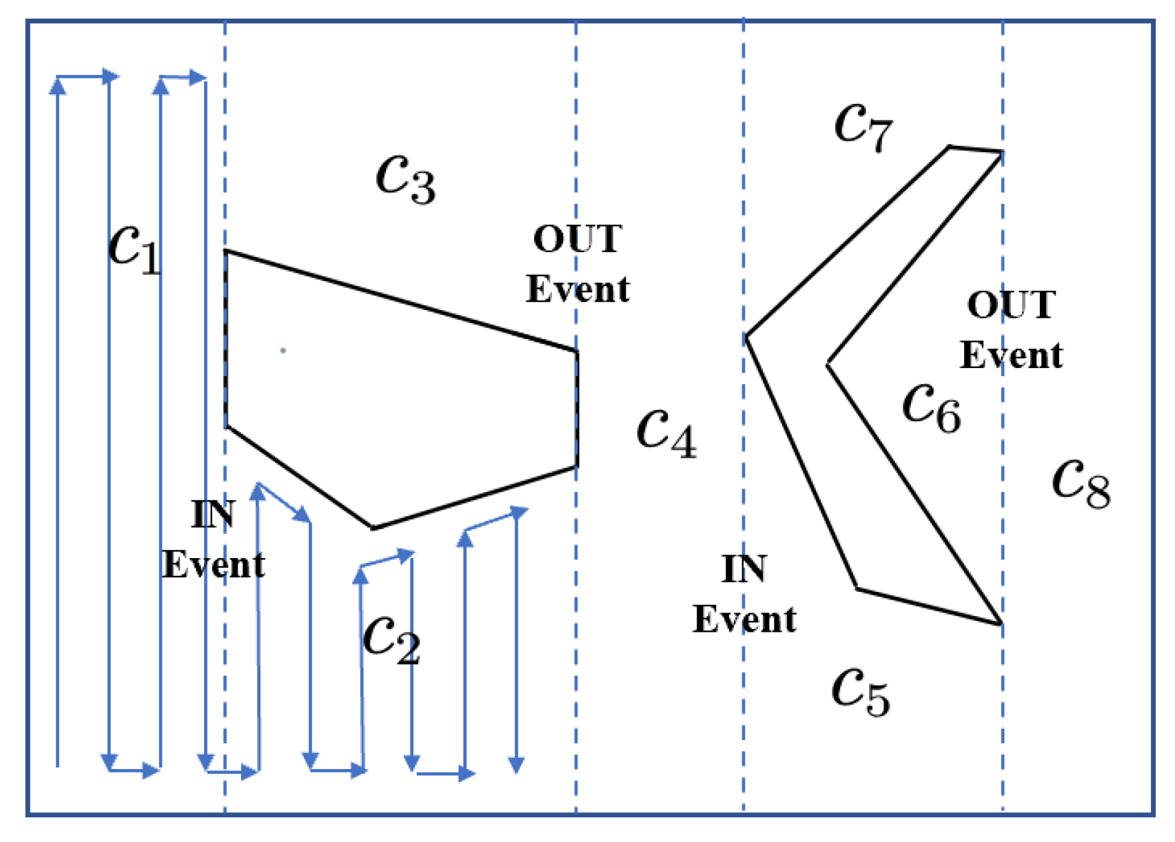
The trapezoidal decomposition method involves sweeping vertical lines, called slices, from left to right, across a bounded environment with polygonal obstacles. Cells are created through a series of opening and closing operations that occur when a slice intersects a vertex of a polygon, triggering an event. These events are categorized as IN, OUT, and MIDDLE. An IN event splits a cell into two, while an OUT event merges two cells into one. During a MIDDLE event, the current cell is closed and a new cell is formed. This process results in the free space being divided into regions of trapezoidal cells.
The Boustrophedon cell decomposition [39] used in this paper is an enhancement of the trapezoidal decomposition designed to minimize the amount of redundant longitudinal motion, as described in the previous paragraph. Essentially, all cells between the IN and OUT events are merged into one cell. We compare the graph’s trapezoidal decomposition with the Boustrophedon decomposition. The Boustrophedon decomposition was found to have a low number of unit regions. Rather than exploiting the structure of polygons to determine the IN and OUT events, this approach relies on changes in slice connectivity to determine the presence of events. The schematic diagram of the Boustrophedon algorithm is shown in Figure 4. The blue dotted line represents In Events or Out Events, and the blue solid line represents the path planned within the segmented area.
In the scanning tasks, USV is limited by the water operation environment and its own motion performance. It has high requirements for the continuity of the coverage path and real-time calculation. Therefore, the method cannot meet the algorithm requirements. Aimed at the limitations of the unit decomposition method, this paper proposes a USV scanning task decomposition method, which converts the space decomposition process into a task decomposition process, and updates the task in real-time to ensure the continuous movement of the USV.

4.2. Contract Network Protocol

In practical applications, since a single USV cannot handle existing tasks alone, cooperation among multiple USVs is necessary. The fundamental approach involves “task assignment, task decoupling, task release, task negotiation, and task coupling,“ ultimately leading to control and decision-making outcomes for complex tasks. This approach ensures that the system meets operational requirements in specific situations with relatively low resource consumption.
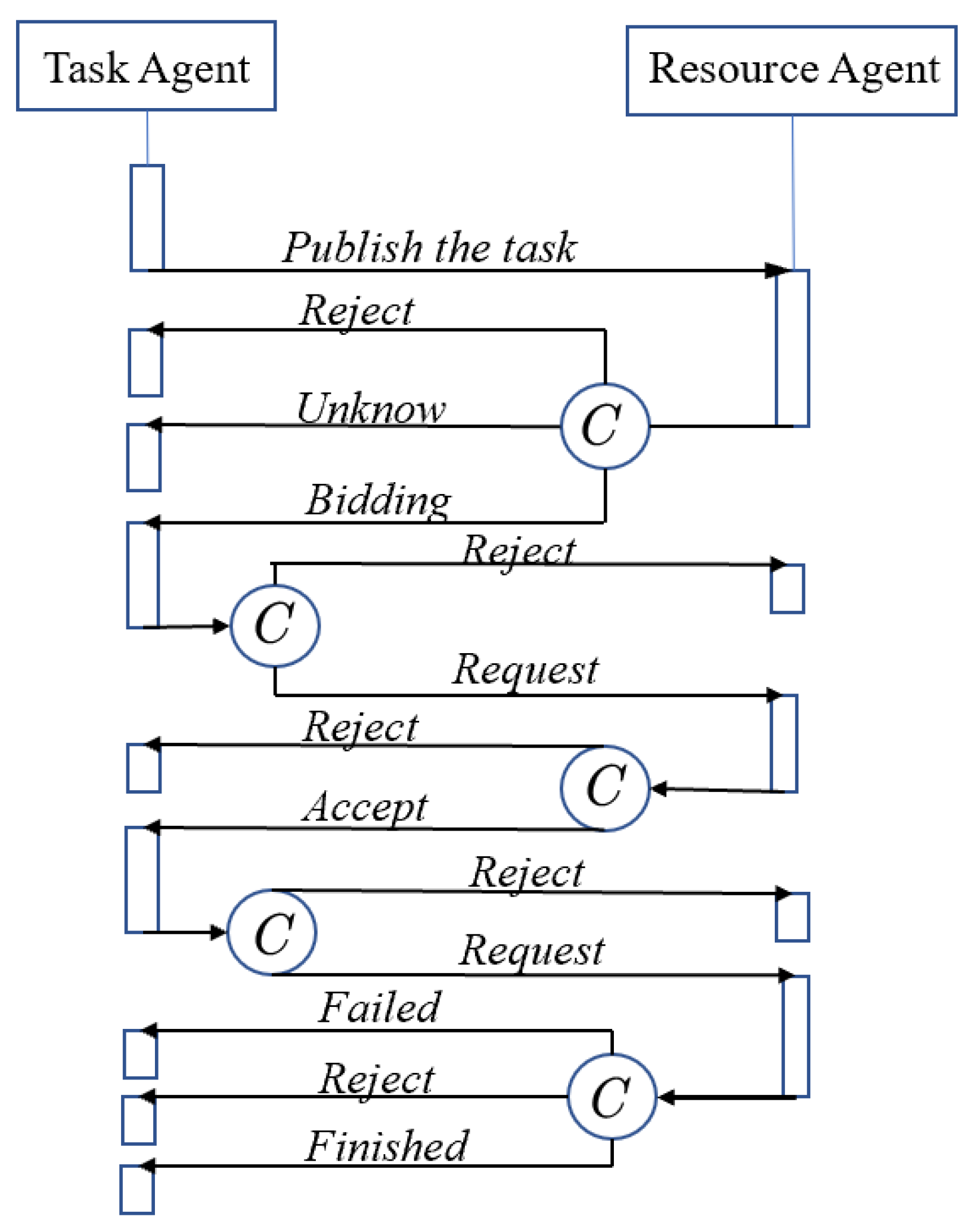
In the contract network model, the task agent is responsible for task decoupling, release, and task coupling. The resource agent is responsible for negotiating sub-tasks to ensure normal task operations. Within this framework, resources maintain a peer-to-peer relationship, acting both as managers and receivers of sub-tasks. The solution to complex tasks is finally realized through direct or indirect interactive communication. The interactive negotiation process within the contract network is shown in Figure 5.
In order to clearly illustrate the multi-USV task scheduling problem, the following assumptions are made:
  • Bidders can evaluate their ability to complete the task.
  • Both the tender USV and the bidder USV are honest and can transmit accurate information to each other.
  • Bidding shall not be changed or canceled during the negotiation process.
  • The communication is reliable. When there is a communication link, there will be no failure, such as information loss during the negotiation process.
The traditional contract network model is suitable for the allocation of a single task and a single successful bidder. With the application of contract network algorithms in many fields, researchers have found that—in complex systems—when task adjustments occur frequently, the efficiency of traditional contract network algorithms is low, and there are many problems, mainly in the following aspects:
(1) The negotiation traffic is large and the delay is long. The task allocation method of the traditional contract network model is applied to a small-scale system. After the bidder broadcasts the task information to all parties without distinction, all parties who meet the conditions will bid. For large-scale systems, there are a large number of tasks that meet the task execution conditions, and the distribution is scattered. To ensure that all possible bidding information is received, the bidding deadline must be extended as the system scale increases, which affects the real-time performance of task allocation.
(2) The traditional contract network model lacks a parallel allocation mechanism. It operates as a single-task, single-winner model, monopolizing all resources from the contract initiation to signing. Since only one bidder ultimately wins the contract for a single task, this approach can lead to issues with idle resources and tasks remaining unassigned in the system.
In view of the above problems faced by the traditional contract network algorithm, and considering the context of real-time collaborative task assignments for USV swarms, this paper adopts the following strategies to improve the contract network:
(1) The tenderer participates in the bidding process, where the bidder initiates the task allocation. The task may either be part of the bidder’s existing task list or a new task identified by them. During real-time task assignment, if the USV itself can execute the task, the task information will include the bidder’s proposed costs as the bidding value. Potential bidders then use this information as a benchmark to decide whether to place their own bids. If the value proposed by the bidder is higher than what it would cost the tenderer to perform the task themselves, the tenderer will withdraw their bid, as it would be more profitable for them to handle the task directly. On the other hand, if the task is suitable for the bidder and can boost the overall revenue of the system, the bidder will submit a bid. By participating in the bidding process, the tenderer sets benchmarks for others, helps identify high-quality bidders, improves negotiation efficiency, and reduces the amount of communication needed.
(2) Introduce concurrency mechanism. The traditional contract network algorithm is a single-task, single-winner model, resulting in low efficiency of task allocation. This paper introduces a concurrency mechanism, and the bidder can choose to bid for one or more tasks in the bidding task. Rather than selecting a single successful bidder, the tenderer selects a combination of successful bidders. The tenderer looks for a combination of bidders who can complete all tasks among bidders and signs a contract with one or more bidders. The concurrency mechanism transforms the auction process from requiring multiple rounds to one round, which greatly improves the negotiation efficiency and effectively reduces the communication frequency.
The traditional contract network can only allocate tasks through the transaction mode of a single task and a single successful bidder. For tasks that need to be auctioned at the same time, they can only be divided into multiple rounds, which makes the entire transaction process take a long time; this is not conducive to the real-time nature of task allocation. In addition, multiple allocations in rounds require multiple communications with the USV swarms, increasing the burden on the communication link. This article discusses a contract network algorithm that utilizes a concurrency mechanism, enabling the simultaneous auctioning of multiple tasks. This approach allows multiple successful bidders to collaborate on completing a task, improving negotiation efficiency and speeding up the task allocation process.
According to the actual USV task allocation situation, this paper proposes a way for tenderers to participate in bidding to improve the allocation performance. First, define the bidding information, which can be described as a tuple of four-dimensional vectors:
< S , P o s s , D i s t b f , D i s t a f >
where S is the auction task set; P o s s denotes the position coordinates of the tasks in the task set; D i s t b f denotes the task path length when the bidder does not execute the task set S; D i s t a f is the task path length when the bidder executes the task set.
We define the tender for the sales contract as a tuple represented by a four-dimensional vector:
< U j , Q , D i s t b f s a l e , D i s t a f s a l e >
where U j is the USV that submits the tender; Q Q S is the task set that the USV applies to buy; D i s t b f s a l e is the current task path length of the bidder; D i s t a f s a l e is the task path length of the bidder’s purchase task set Q.
The cooperative real-time task allocation algorithm of USVs based on an improved contract network is described as follows:
Step 1: Determine the tender for USVs. In the allocation of USV tasks, the selection of tenderer is determined based on three unexpected situations: if a new task is discovered or the USV is damaged, the USV with the least current tasks will be responsible for the auction as the bidder; if subsequent tasks cannot be performed due to unknown obstacles, the USV that owns the task will be responsible for the auction.
Step 2: Publish the tender information < S i , P o s s , D i s t bf , D i s t af > . Tender U i announces to other USVs the details regarding the set of tasks, S i , that are available for auction.
Step 3: Bidder competency assessment. After receiving the bidding information for the bidding of the USV U i , other USVs evaluate their own capabilities and judge whether to submit the tender.
Step 4: Tender matching. If there is a set of bidders, and the collection of tasks they apply to purchase or exchange corresponds exactly to the collection of these bidders, and if the receipt of the bidder U j tender < U j , Q 1 , D i s t bf sale , D i s t af sale > and bidder U k exchange contract bid < U k , Q 2 , Z , D i s t bf s w a p , D i s t af s w a p > meet Q 1 Q 2 = S i , Q 1 Q 2 = , then the set of bidders is said to be matched. The tender unmanned ship matches the bids received within the specified tender deadline and selects them to complete the task assignment.
Step 5: Notification of tender results. The bidding USV sends the bidding result to the bidding USV. As in the above example, USVs U j and U k are the winning bidders, and the rest of the USVs are the bidders.
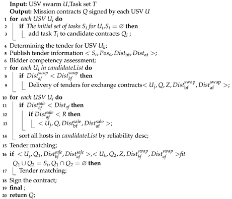
Step 6: Sign the contract. After receiving the winning information, the winning USV signs a contract with the tendered USV to complete the replacement of ownership of the task set. The pseudo code of the improved contract network algorithm is shown in Algorithm 1.
Algorithm 1: Improved contract network algorithm.
Jmse 13 00672 i001

4.3. B-CNP Algorithm

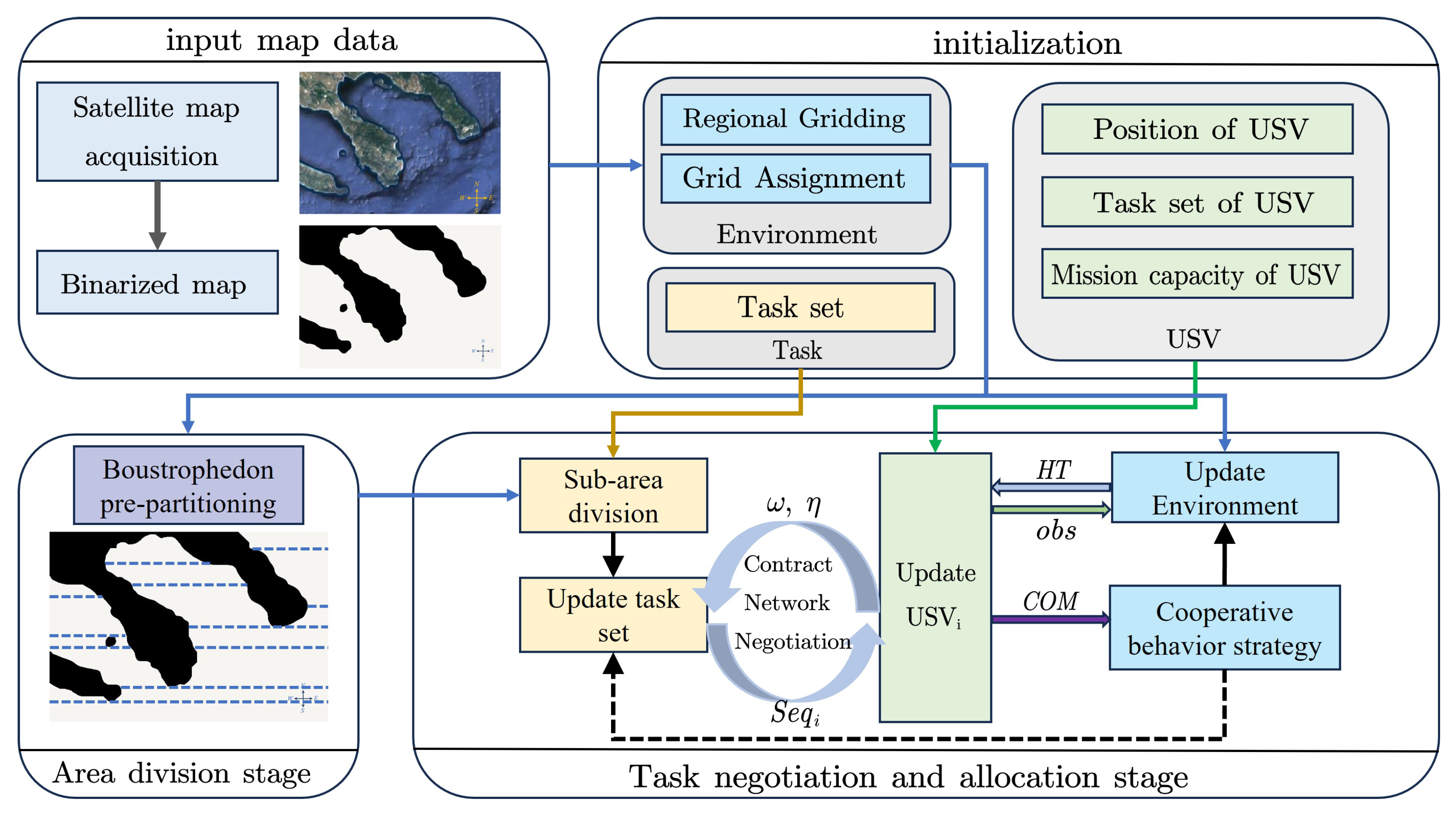
The B-CNP algorithm pre-divides the total task on the basis of the Boustrophedon algorithm and incorporates an improved contract network protocol so that the USV swarm can collaboratively cover the entire water area.
Based on the USV task decomposition and scanning scene map update method, the B-CNP algorithm is proposed. The algorithm flow is as follows, and its main process is as follows:
Step 1: Initialization—initialize the task map, assign B V α 0 to each grid according to the preset, then import the environment map, enter the coordinates, and continuously update the preset map. Initialize the USV parameters, set the starting position and mission constraints;
Step 2: Use the Boustrophedon algorithm to pre-segment the map task area;
Step 3: The USV outputs its own position information ω and obstacle information η , uses the improved contract network algorithm to assign tasks between communicable USVs, and starts updating the map;
Step 4: The map outputs the grid status list H T in the real-time update, the map accepts the map information and USV information input, and updates B V α ;
Step 5: The unmanned boat cluster updates the task list S e q and the unmanned boat’s own position information, ω , as well as the communication matrix C O M in real-time;
Step 6: If no new tasks are found and the unmanned boat cluster completes all tasks or all unmanned boats reach the constraint limit, the algorithm ends; otherwise, it returns to Step 3.
The framework diagram of the B-CNP algorithm is shown in Figure 6, and the pseudo code of the algorithm is expressed as Algorithm 2.
Algorithm 2: B-CNP algorithm
Jmse 13 00672 i002

4.4. The Complexity of the B-CNP Algorithm

4.4.1. Time Complexity

Set the map size to M × N , plan n sub-tasks through Boustrophedon’s algorithm, and set m agents. Boustrophedon’s algorithm scans the map globally and completes the decoupling of the global map task. The time complexity of the Boustrophedon decomposition is O(p log p) (p is the number of vertices on the obstacle edge), and its linear logarithmic property comes from the dynamic region partitioning strategy based on scan lines. Each agent evaluates the sub-task, and the time complexity is O ( m × n ) . In the task negotiation stage, each agent combines the remaining n m sub-tasks and gives the time cost of each potential sub-task; the maximum number of calculations required is as follows: i = 1 n m C i n , and the time complexity is O n n m . In the task-coupling stage, the unfinished k tasks are released, each agent bids, and the time complexity is O ( k × m ) .

4.4.2. Space Complexity

We set the map size to M × N , plan sub-tasks through Boustrophedon’s algorithm, and set m agents. The Boustrophedon algorithm scans the map globally and completes the decoupling of the global map task, with a spatial complexity of O ( M × N ) . Each agent evaluates the sub-task and adds the first task to the execution task collection; the spatial complexity is O ( m ) , the task status is updated in the task set, and the spatial complexity is O ( n ) . In the task negotiation stage, each agent and the set of tasks are updated in real-time and the spatial complexity is O ( ( m + n ) × t ) . In the task-coupling stage, the unfinished k tasks are re-released, with each agent submitting a bid; the space complexity is O ( k + m ) .

5. Simulation Experiments

This section mainly performs the simulation of the coverage path planning of USVs in complex environments and analyzes the performance of Boustrophedon’s algorithm [28], BA* algorithm [23], CCIBA* [14], and the B-CNP algorithm in terms of path length and coverage efficiency. Then, the performance parameters of the B-CNP algorithm in the island and reef environment are verified by simulation in the real sea area to guide the actual bathymetry task. Finally, the dynamic environment setting is added to display the mission performance of the USV cluster in the environment of dynamic obstacles. All simulation experiments are implemented based on Matlab (version 2023a).

5.1. Area Coverage Under Tectonic Waters

According to the path planning algorithm, as shown in Figure 7, the map area is evenly occluded, and four USVs start to cover each unit. As shown in Figure 7a, it can be seen that using the Boustrophedon algorithm results in a longer backtracking path with more turns. As shown in Figure 7b,c, the BA* algorithm, as an online algorithm, cannot bypass the obstacle area to reach the unsearched task area. Compared with the BA* algorithm, the CCIBA* algorithm can perform region exchange after the region is uniformly partitioned, thereby reducing the back-tracking path. The B-CNP algorithm is different from the manual pre-division of the above three algorithms. The B-algorithm is used to pre-scan the area, and then using the contract network protocol, each unmanned ship can obtain its own task area allocation without manual pre-division.
From Figure 8, it can be seen intuitively that compared with the other three algorithms, the B-CNP algorithm has a more uniform distribution coverage path length for USVs, because the B-CNP algorithm allocates tasks in real-time. The problem of uneven task distribution caused by artificially assigning task areas is avoided.
The coverage path lengths of the unmanned ships of the four algorithms are shown in Table 1. The path lengths are 6985.6 for the Boustrophedon algorithm, 6283.9 for the BA* algorithm, and 6226.3 for the CCIBA* algorithm. Compared with the Boustrophedon algorithm, the BA* algorithm reduces by about 10.04% because the BA* algorithm does not completely traverse the delineated task area. Compared with the BA* algorithm, the CCIBA* algorithm reduces the path length by about 0.92%. A well-established backtracking mechanism also creates unnecessary paths, ultimately limiting its improvement. The coverage path length of the B-CNP algorithm proposed in this paper is reduced by about 12.95% compared with the Boustrophedon algorithm, reduced by about 3.25% compared with the BA* algorithm, and reduced by about 2.33% compared with the CCIBA* algorithm. Scanning line utilization is the ratio of effective scan line length to total scan line length, which is used to measure the resource utilization efficiency during the scanning process. Compared with the four algorithms, B-CNP has the highest scan line utilization. This benefit is largely due to the drastic reduction in unit counts and the positive effects of innovative methods for updating maps and missions.
In addition, the B-CNP algorithm performs better than the other three algorithms in terms of coverage and turn times, because the artificial division of the task area will make the task area discontinuous and increase the number of turns.
The coverage efficiency of the four algorithms is shown in Table 2. The speed of USV is 30 grids per unit of time, and the coverage radius is 5 grids. Two evaluation indicators are selected here, namely the total mission time and the number of grids effectively covered by the USV per unit of time. The total mission time of the B-CNP algorithm proposed in this paper is reduced by about 22.5% compared with the Boustrophedon algorithm, about 22.5% compared with the BA* algorithm, and about 7.1% compared with the CCIBA* algorithm; the number of grids effectively covered per unit of time is increased by about 23.3% compared with the Boustrophedon algorithm, about 24.0% compared with the BA* algorithm, and about 7.5% compared with the CCIBA* algorithm.

5.2. Path Overlay Simulation Under Real Water

Figure 9 illustrates the coverage paths of eight unmanned vehicles. It is evident from these figures that the B-CNP algorithm effectively minimizes the generation of redundant paths, while still ensuring comprehensive coverage of the designated task area. These visual representations provide empirical evidence that the B-CNP algorithm successfully optimizes the path planning process, resulting in an efficient and thorough coverage of the mission area by unmanned vehicles.
Figure 9 shows the water area coverage path planning results of eight unmanned boats. The paths and their corresponding results are described as follows: USV3 initially reaches the mission boundary and then begins to circle around the island. Ultimately, it manages to complete its mission on one track. USV4, USV6, and USV8 complete the coverage task without encountering a local optimum. They navigate the area efficiently and effectively. Once USV1, USV2, USV5, and USV7 enter the concave area, the coverage mission starts as planned. They successfully complete the bypass and finally complete the coverage task. USV3 successfully scans the waters near the island to achieve full coverage. The schematic diagram in the figure represents the path that USV3 will eventually take. These planning results demonstrate the effectiveness of the algorithm in guiding the UAV to effectively cover the mission area. The paths taken by each vessel illustrate their ability to circumvent obstacles and complete coverage tasks, demonstrating the success of the planning process.
After final calculation, USV1 accounts for about 8.59% of the path in this mission, and USV2 accounts for about 9.13% of the path. USV3 takes about 11.30% of the path, USV4 takes about 12.05%, USV5 takes about 13.66%, USV6 takes about 15.33%, USV8 takes about 14.05%, and USV8 takes about 15.89%, which basically corresponds to the performance of each ship in the mission. The final path coverage is 99.6%, which meets the coverage requirements of multi-person unmanned survey ships.
Figure 10 shows the path coverage length of each ship and the total path length to complete the task for the three algorithms. The simulated results for the real graphs are consistent with those for the generated map graphs. The B-CNP algorithm requires a shorter coverage path, and each unmanned vehicle is assigned a more even task.
From Figure 10, it can be seen that, compared with the other three algorithms, the B-CNP algorithm has a more uniform distribution coverage path length for unmanned vehicles, because the B-CNP algorithm allocates tasks in real-time. The problem of uneven task distribution caused by artificially assigning task areas is avoided. In Scenario 2 and Scenario 3, there are seven and nine USVs as shown in the figure, respectively, and their head coverage is shown in Figure 11 and Figure 12. It can be seen from the coverage path that the unmanned boat can better perform collaborative tasks and has fewer backtracking paths.
It can be seen from Table 3 that the coverage path lengths of the B-CNP algorithm in Scenario 1 are 6.08%, 1.89%, and 0.89% less than those of the Boustrophedon algorithm, BA* algorithm, and CCIBA* algorithm. And the coverage rates are 1.25%, 3.74%, and 1.22% higher than these three algorithms. The coverage path lengths of the B-CNP algorithms in Scenario 2 are 8.43%, 1.38%, and 1.52% less than those of the Boustrophedon algorithm, BA* algorithm, and CCIBA* algorithm. And the coverage rates are 1.26%, 3.76%, and 1.22% higher than these three algorithms. The coverage path lengths of the B-CNP algorithm in Scenario 3 are 10.25%, 5.49%, and 1.48% less than those of the Boustrophedon algorithm, BA* algorithm, and CCIBA* algorithm. And the coverage rates are 2.06%, 6.25%, and 0.62% higher than these three algorithms. Based on the data provided, it becomes evident that as the scene complexity escalates, the B-CNP algorithm exhibits enhanced performance when compared to both the BA* algorithm and the Boustrophedon algorithm. This improvement is attributed to the B-CNP algorithm’s flexibility, as it does not adhere to a fixed task area. This adaptability allows unmanned boats to adjust mission areas through communication, thereby mitigating the need for unnecessary backtracking paths. At the same time, the advantages of the B-CNP algorithm compared to the CCIBA* algorithm are relatively stable.
As can be seen from Table 4, in the three scenarios, the total time of the B-CNP algorithm to complete the task is faster than that of the other algorithms. On the other hand, the number of grids covered per unit of time is greater. For example, in scenario 1, the times are reduced by 13.2%, 9.7%, and 10.2%, respectively, compared with the three algorithms, and the grids covered per unit of time of the three algorithms are 13.2%, 15.9% and 10.2% higher, respectively. From the data provided, it can be seen that the B-CNP algorithm shows better performance.

5.3. Path Overlay Simulation in Dynamic Environments

Figure 13 presents simulations demonstrating sudden encounters with unknown static obstacles and damage during a mission involving USV. While performing a coverage mission, USV2 detects an unknown static obstacle that blocks its planned trajectory. At the same time, unfinished missions are published, and other USVs within the communication range participate in bidding to complete the final mission. The specific results of the bidding process are shown in Figure 13. At t = 45 s, the obstacle area appears. At t = 58 s, USV2 detects an obstacle and its hull is damaged, making it unable to perform subsequent missions. USV2 publishes an unfinished new mission, and other unmanned boats (USV3 and USV4) in the communication area participate in the bidding; finally, USV3 successfully wins the bid. The final coverage path length is 6253.8, and the coverage rate is 99.87%. By releasing tasks and facilitating bidding among unmanned vehicles, the system ensures task continuity and efficient task allocation, allowing the mission to proceed despite these unforeseen circumstances.
An experiment was conducted on a real ocean map to simulate the path coverage of the USVs. In the experiment, two unknown static obstacles were introduced at t = 100 s and t = 115 s, respectively. The figure illustrates the resulting path coverage of the USVs. During the experiment, the USVs were able to avoid colliding with the obstacles. The diagram in Figure 14 represents the path coverage at the end of the task. The final path length covered by the USV is 23,319.8 and the coverage is 98.83%. This experiment demonstrates the capability of the unmanned boat cluster to adapt to unforeseen obstacles in real-world scenarios. By avoiding collisions and adjusting their paths, the cluster effectively completes the coverage task while ensuring the safety of the unmanned boats. The results of the experiment provide valuable insight into the practical application of the proposed system in dynamic environments.
Figure 15 illustrates the coverage paths generated by the B-CNP algorithm in a simulated scene involving known dynamic obstacles. This figure depicts a USV encountering a vessel sailing on an unknown course. According to international rules for avoiding collisions at sea, the USV changes course vertically to avoid another vessel. As shown in Figure 15, after successfully passing through the potential collision zone with the ship, the USV resumes its normal navigation mode. Then, while continuing its coverage mission, the USV encounters another ship. In this case, the USV sails past the other vessel’s port side, adhering to proper collision avoidance protocols. Once again, the USV continues its coverage mission without interruption after traversing the relevant hazard zone. This simulated scenario demonstrates the ability of the B-CNP algorithm to efficiently handle encounters with dynamic obstacles such as ships.
As shown in Figure 15, the red asterisk represents a dynamic obstacle, and its circumscribed circle represents the boundary range of the obstacle. The dynamic obstacle moves randomly in the map area. When the surface unmanned vehicle detects the obstacle, it avoids it in a direction perpendicular to the obstacle and the direction of movement and re-issues the unfinished task. This algorithm enables the unmanned surface vehicle to avoid dynamic obstacles safely and efficiently, ensuring the completion of the coverage task.

6. Conclusions

In this paper, a new uninterrupted surface cover path planning method is proposed to facilitate the USV swarm to complete the task in marine data sampling; its performance was studied through a large number of simulation studies. The proposed path planning system was designed to efficiently navigate a series of ordered tasks in a given water area. The system follows a systematic approach, starting with the extraction of the map area using an exploration-based approach. The area is divided into task intervals using the Boustrophedon algorithm. Subsequently, the distributed contract network protocol algorithm dynamically assigns search tasks to the unmanned surface vehicle (USV) cluster. To optimize the cluster’s search efficiency, a hybrid contract network protocol for dynamic task scheduling is introduced. This protocol includes various contract types such as purchase and sale contracts, exchange contracts, and replacement contracts. These contracts enable the real-time allocation of tasks to each boat in the cluster until the entire water area is covered. By employing this proposed path planning system, the overall efficiency of the cluster’s search operations can be maximized, ensuring effective coverage of the specified tasks. This system combines exploration, task interval division, dynamic task allocation, and a hybrid contract network protocol to achieve efficient and real-time task scheduling in a USV cluster.
From the simulation comparison experiment, it can be seen that in a larger scale scenario (scenario 3), the B-CNP algorithm has coverage rate increases of 2.06%, 6.52%, and 0.62%; scanning line utilization rate increases of 5.99%, 1.54%, and 1.12%; task completion time reductions of 8.78%, 2.03%, and 3.44%; and total coverage path length reductions of 10.25%, 5.49%, and 1.48% compared with the Boustrophedon, BA*, and CCIBA* algorithms, so it has better performance. In addition, in the scenario of unknown dynamic obstacles, the coverage task is also completed well. The system combines exploration, task interval division, dynamic task allocation, and the hybrid contract network protocol to achieve efficient and real-time task scheduling in the USV cluster. Therefore, the path planning system of this study enables the USV to handle multiple performance goals while being computationally suitable for real-time implementation.
Although this study has made some progress in the multi-surface unmanned boat task area division algorithm, there are still some limitations, providing an important direction for future research. This study has simplified the performance difference analysis in the task area division stage. Subsequent research needs to further combine the actual performance parameters of the detection equipment, optimize the robustness and computational efficiency of the algorithm, and improve its applicability in complex environments and diversified tasks. In addition, the impact of communication capabilities between unmanned boats on the coverage of the collaborative area has not been deeply explored. In the future, the focus should be on studying the adaptability of the algorithm under actual constraints such as communication protocols, delays, and bandwidth limitations, and developing emergency mechanisms when communication is interrupted. By expanding the scale of experiments, conducting long-term field tests, and promoting industry–university–research cooperation, it is anticipated that the task execution capabilities of multi-surface unmanned boat systems in complex marine environments will be enhanced, providing more reliable technical support for fields such as marine resource development, environmental monitoring, and emergency rescue.

Author Contributions

X.J.: Conceptualization, methodology, software, validation, investigation, writing—original draft. X.F.: Conceptualization, supervision, writing—review and editing. All authors have read and agreed to the published version of the manuscript.

Funding

This work was supported by the Equipment Pre-Research Ministry of Education Joint Fund [grant number 6141A02033703].

Data Availability Statement

The datasets generated and analyzed during the current study are available from the corresponding author upon reasonable request.

Acknowledgments

The authors gratefully acknowledge the financial support provided by this fund, which made this research possible.

Conflicts of Interest

The authors declare that they have no known competing financial interests or personal relationships that could have appeared to influence the work reported in this paper.

Abbreviations

NotationsDefinition
Hthe map space
Nthe maximum value of the grid sequence
h α the grid individual space
o b s obstacle area
c o v free space has been covered
f z free space not covered
n z no-navigation area
H T environmental state list
B V α initial value of each grid
Tset of tasks
N T the number of tasks
N u the number of USVs
Uthe set of USVs
S e q i the task sequence of the i t h USV U i
Dthe maximum range of the USV
N s maximum task capacity
Pthe set of environment constraints
C O M the communication matrix of USVs
t r _ S e q i j the exchange sequence of U S V i and U S V j
ω location information of USV
η location information of obstacles

References

  1. Miao, R.; Pang, S.; Jiang, D. Complete traversal path planning for marine autonomous aircraft in multi-bay areas. Signal Image Video Process. 2019, 18, 3275–3284. [Google Scholar]
  2. Fevgas, G.; Lagkas, T.; Argyriou, V.; Sarigiannidis, P. Coverage path planning methods focusing on energy efficient and cooperative strategies for unmanned aerial vehicles. Sensors 2022, 22, 1235. [Google Scholar] [CrossRef] [PubMed]
  3. Liu, Y.; Peng, Y.; Wang, M.; Xie, J.; Zhou, R. Multi-usv system cooperative underwater target search based on reinforcement learning and probability map. Math. Probl. Eng. 2020, 2020, 7842768. [Google Scholar]
  4. Lv, X.; Cheng, Q.; Li, S. Complete Traversal Path Planning for Unmanned Ship Based on Improved A* Algorithm. J. Unmanned Syst. 2019, 6, 6647. [Google Scholar]
  5. Jin, X.; Er, M.J. Cooperative path planning with priority target assignment and collision avoidance guidance for rescue unmanned surface vehicles in a complex ocean environment. Adv. Eng. Inform. 2022, 52, 101517. [Google Scholar]
  6. Ye, Z.; Wang, K.; Chen, Y.; Jiang, X.; Song, G. Multi-UAV navigation for partially observable communication coverage by graph reinforcement learning. IEEE Trans. Mob. Comput. 2022, 22, 4056–4069. [Google Scholar]
  7. Ma, Y.; Hu, M.; Yan, X. Multi-objective path planning for unmanned surface vehicle with currents effects. ISA Trans. 2018, 75, 137–156. [Google Scholar]
  8. MahmoudZadeh, S.; Abbasi, A.; Yazdani, A.; Wang, H.; Liu, Y. Uninterrupted path planning system for Multi-USV sampling mission in a cluttered ocean environment. Ocean. Eng. 2022, 254, 111328. [Google Scholar]
  9. Smith, T.; Mukhopadhyay, S.; Murphy, R.R.; Manzini, T.; Rodriguez, I. Path coverage optimization for usv with side scan sonar for victim recovery. In Proceedings of the 2022 IEEE International Symposium on Safety, Security, and Rescue Robotics (SSRR), Sevilla, Spain, 8–10 November 2022; pp. 160–165. [Google Scholar]
  10. Sudha, S.K.R.; Mishra, D.; Hameed, I.A. A coverage path planning approach for environmental monitoring using an unmanned surface vehicle. Ocean. Eng. 2024, 310, 118645. [Google Scholar]
  11. Zhao, L.; Bai, Y. Energy efficient coverage path planning for USV-assisted inland bathymetry under current effects: An analysis on sweep direction. Ocean Eng. 2024, 305, 117910. [Google Scholar]
  12. Kvitko, D.; Rybin, V.; Bayazitov, O.; Karimov, A.; Karimov, T.; Butusov, D. Chaotic Path-Planning Algorithm Based on Courbage–Nekorkin Artificial Neuron Model. Mathematics 2024, 12, 892. [Google Scholar] [CrossRef]
  13. Xiang, T.; Wang, H.; Shi, Y. A multi-machine cooperative detection task assignment strategy for area coverage. J. Air Force Eng. Univ. 2020, 20, 33–38. [Google Scholar]
  14. Ma, Y.; Zhao, Y.; Li, Z.; Bi, H.; Wang, J.; Malekian, R.; Sotelo, M.A. CCIBA*: An Improved BA* Based Collaborative Coverage Path Planning Method for Multiple Unmanned Surface Mapping Vehicles. IEEE Trans. Intell. Transp. Syst. 2022, 23, 19578–19588. [Google Scholar]
  15. Cao, L.; Chen, Q. Cooperative path planning for multi-USV based on improved artificial bee colony algorithm. In Proceedings of the MIPPR 2017: Remote Sensing Image Processing, Geographic Information Systems, and Other Applications, Xiangyan, China, 28–29 October 2017; SPIE: Washington, DC, USA, 2018; Volume 10611, pp. 352–359. [Google Scholar]
  16. Zhao, P.; Li, J.; Mao, Z.; Ding, W. Cooperative Search Path Planning for Multiple Unmanned Surface Vehicles. In Proceedings of the 2022 International Conference on Autonomous Unmanned Systems (ICAUS 2022), Xi’an, China, 23–25 September 2022; Springer: Berlin/Heidelberg, Germany, 2023; pp. 3434–3445. [Google Scholar]
  17. Yao, Y.; Cao, J.H.; Guo, Y.; Fan, Z.; Li, B.; Xu, B.; Li, K. Adaptive coverage control for multi-USV system in complex environment with unknown obstacles. Int. J. Distrib. Sens. Netw. 2021, 17, 15501477211021525. [Google Scholar]
  18. Zhao, Z.; Zhu, B.; Zhou, Y.; Yao, P.; Yu, J. Cooperative Path Planning of Multiple Unmanned Surface Vehicles for Search and Coverage Task. Drones 2023, 7, 21. [Google Scholar]
  19. Wen, J.; Liu, S.; Lin, Y. Dynamic navigation and area assignment of multiple USVs based on multi-agent deep reinforcement learning. Sensors 2022, 22, 6942. [Google Scholar] [CrossRef] [PubMed]
  20. Li, J.; Li, X.; Yu, L. Multi-UAV cooperative coverage path planning in plateau and mountain environment. In Proceedings of the 2018 33rd Youth Academic Annual Conference of Chinese Association of Automation (YAC), Nanjing, China, 18–20 May 2018; IEEE: Piscataway, NJ, USA, 2018; pp. 820–824. [Google Scholar]
  21. Yao, P.; Lou, Y.; Zhang, K. Multi-USV cooperative path planning by window update based self-organizing map and spectral clustering. Ocean. Eng. 2023, 275, 114140. [Google Scholar]
  22. Yuan, G.; Xiao, J.; He, J.; Jia, H.; Wang, Y.; Wang, Z. Multi-agent cooperative area coverage: A two-stage planning approach based on reinforcement learning. Inf. Sci. 2024, 678, 121025. [Google Scholar] [CrossRef]
  23. Chen, X.; Yuan, Y.; Rao, D. Application of an improved A* algorithm in unmanned ship path planning. Comput. Simul. 2021, 38, 277–281. [Google Scholar]
  24. Huang, X.; Yuan, H.; Bi, J. DQN-based Naval Battleship Path Planning and Simulation. J. Syst. Simul. 2021, 33, 2440. [Google Scholar]
  25. Dias, M.B.; Zlot, R.; Kalra, N.; Stentz, A. Market-based multirobot coordination: A survey and analysis. Proc. IEEE 2006, 94, 1257–1270. [Google Scholar] [CrossRef]
  26. Zhang, J.; Wang, G.; Song, Y. Task assignment of the improved contract net protocol under a multi-agent system. Algorithms 2019, 12, 70. [Google Scholar] [CrossRef]
  27. Zhang, Z.; Liu, H.; Wu, G. A Dynamic Task Scheduling Method for Multiple UAVs Based on Contract Net Protocol. Sensors 2022, 22, 4486. [Google Scholar] [CrossRef] [PubMed]
  28. Chen, J.; Sun, D. Coalition-based approach to task allocation of multiple robots with resource constraints. IEEE Trans. Autom. Sci. Eng. 2012, 9, 516–528. [Google Scholar] [CrossRef]
  29. Vovos, P.N.; Kiprakis, A.E.; Wallace, A.R.; Harrison, G.P. Centralized and distributed voltage control: Impact on distributed generation penetration. IEEE Trans. Power Syst. 2007, 22, 476–483. [Google Scholar] [CrossRef]
  30. Yuan, W.; Wu, N.; Etzlinger, B.; Li, Y.; Yan, C.; Hanzo, L. Expectation–maximization-based passive localization relying on asynchronous receivers: Centralized versus distributed implementations. IEEE Trans. Commun. 2018, 67, 668–681. [Google Scholar] [CrossRef]
  31. Han, X.; Mandal, S.; Pattipati, K.R.; Kleinman, D.L.; Mishra, M. An optimization-based distributed planning algorithm: A blackboard-based collaborative framework. IEEE Trans. Syst. Man, Cybern. Syst. 2013, 44, 673–686. [Google Scholar] [CrossRef]
  32. Liu, G.; Wang, Y.; Zhang, F. Contract Network Protocol Negotiation Mechanism Convergence and Convergence Rate Analysis. Control Decis. Mak. 2014, 29, 1027–1034. [Google Scholar]
  33. Zhang, H.; Shi, Z. Dynamic Contract Network Protocol. Comput. Eng. 2004, 30, 44–46. [Google Scholar]
  34. Jiang, J.; Yang, X.; Yin, M. Analysis of Task Allocation among Multi-Teams of Remote Distributed Agile Development Based on Contract Network Protocol. Technol. Manag. Res. 2019, 3. [Google Scholar]
  35. Ying, Y. Cooperative task assignment of multiple UCAVs based on MAS and CNP. In Proceedings of the 2013 IEEE International Conference on Granular Computing (GrC), Beijing, China, 13–15 December 2013; IEEE: Piscataway, NJ, USA, 2013; pp. 391–395. [Google Scholar]
  36. Liu, Y.; Zhang, A. Cooperative task assignment method of manned/unmanned aerial vehicle formation. Syst. Eng. Electron. 2010, 32, 584–588. [Google Scholar]
  37. Liang, H.; Kang, F. A novel task optimal allocation approach based on Contract Net Protocol for Agent-oriented UUV swarm system modeling. Optik 2016, 127, 3928–3933. [Google Scholar]
  38. Zhen, Z.; Wen, L.; Wang, B.; Hu, Z.; Zhang, D. Improved contract network protocol algorithm based cooperative target allocation of heterogeneous UAV swarm. Aerosp. Sci. Technol. 2021, 119, 107054. [Google Scholar]
  39. Choset, H.; Pignon, P. Coverage path planning: The boustrophedon cellular decomposition. In Field and Service Robotics; Springer: Berlin/Heidelberg, Germany, 1998; pp. 203–209. [Google Scholar]
Figure 1. Map of sea areas to be covered.
Jmse 13 00672 g001
Figure 2. USV swarm-planning element map.
Jmse 13 00672 g002
Figure 3. Schematic diagram of the final coverage path of the algorithms; (a) obstacle recognition; (b) distributed communication; and (c) regional transfer.
Jmse 13 00672 g003
Figure 4. A Boustrophedon motion and the Boustrophedon cellular decomposition (BCD).
Jmse 13 00672 g004
Figure 5. United network protocol UML sequence diagram.
Jmse 13 00672 g005
Figure 6. B-CNP algorithm flow chart.
Jmse 13 00672 g006
Figure 7. Schematic diagram of the final coverage path of the algorithms; (a) Boustrophedon, (b) BA*, (c) CCIBA*, (d) B-CNP.
Jmse 13 00672 g007
Figure 8. Schematic diagram of path length distributions.
Jmse 13 00672 g008
Figure 9. Schematic diagram of the final coverage path of the B-CNP algorithm in scenario 1.
Jmse 13 00672 g009
Figure 10. Schematic diagram of the path length distribution of USVs in the real sea area.
Jmse 13 00672 g010
Figure 11. Schematic diagram of the final coverage path of the B-CNP algorithm in scenario 2.
Jmse 13 00672 g011
Figure 12. Schematic diagram of the final coverage path of the B-CNP algorithm in scenario 3.
Jmse 13 00672 g012
Figure 13. Collaboratively complete the coverage tasks after encountering obstacles.
Jmse 13 00672 g013
Figure 14. The USVs complete the coverage task after encountering an unknown obstacle.
Jmse 13 00672 g014
Figure 15. The USVs complete the coverage task after encountering dynamic obstacles. (a) t = 5 s, (b) t = 15 s, (c) t = 45 s, (d) t = 85 s, (e) t = 105 s, (f) t = 115 s.
Jmse 13 00672 g015
Table 1. Analysis table OF BA*, Boustrophedon, CCIBA*, and B-CNP.
AlgorithmsUSVPath LengthPercentageTurningCoverage RateScanline Utilization
BoustrophedonUSV11604.722.97%1398.35%91.6%
USV21401.920.07%1498.82%92.3%
USV31624.823.26%1297.20%88.5%
USV42354.233.70%16100%100%
Summation6985.65598.71%94.54%
BA*USV11368.821.78%1295.27%100%
USV21401.922.31%1498.82%93.3%
USV31159.018.45%1394.96%100%
USV42354.237.46%13100%100%
Summation6283.95197.76%98.51%
CCIBA*USV11567.425.17%1599.45%100%
USV21060.617.03%998.84%100%
USV31635.126.26%1198.48%100%
USV41963.231.53%12100%99.2%
Summation6226.34599.25%99.74%
B-CNPUSV11565.225.74%1599.64%100%
USV21824.830.01%1199.27%100%
USV31399.123.00%5100%100%
USV41292.221.25%8100%100%
Summation6081.33999.68%100%
Table 2. Coverage efficiency comparison of algorithms.
AlgorithmsTotal Mission Time (TMT)Coverage per Second (CPS)
Boustrophedon78.47409.74
BA*78.47405.81
CCIBA*65.43494.04
B-CNP60.80534.00
Table 3. Analysis table of BA*, Boustrophedon, CCIBA*, and B-CNP in three scenes.
ScenesAlgorithmsPath LengthCoverage RateScanning Line Utilization
Scenario1Boustrophedon24,409.498.35%93.86%
BA*23,365.495.86%97.29%
CCIBA*23,129.598.38%98.85%
B-CNP22,924.199.60%99.13%
Scenario2Boustrophedon28,463.497.92%92.41%
BA*26,595.893.33%97.82%
CCIBA*26,634.298.12%97.94%
B-CNP26,228.598.47%98.45%
Scenario3Boustrophedon36,054.996.27%92.03%
BA*34,240.892.15%96.38%
CCIBA*32,847.597.68%96.97%
B-CNP32,360.398.29%97.89%
Table 4. Coverage efficiency of BA*, Boustrophedon, CCIBA*, and B-CNP in three scenes.
ScenesAlgorithmsTotal Mission Time (TMT)Coverage per Second (CPS)
Scenario1Boustrophedon152.65456.36
BA*146.85441.78
CCIBA*147.60472.02
B-CNP132.50525.60
Scenario2Boustrophedon254.13445.56
BA*241.45445.89
CCIBA*246.17459.81
B-CNP224.13508.23
Scenario3Boustrophedon290.97442.92
BA*270.93455.31
CCIBA*274.90475.68
B-CNP265.43495.72
Disclaimer/Publisher’s Note: The statements, opinions and data contained in all publications are solely those of the individual author(s) and contributor(s) and not of MDPI and/or the editor(s). MDPI and/or the editor(s) disclaim responsibility for any injury to people or property resulting from any ideas, methods, instructions or products referred to in the content.

