1. Introduction
The transportation industry, particularly the maritime industry, is one of the major contributors of greenhouse gas (GHG) emissions because of the extensive use of diesel engines that use fossil fuels as the main power source. The total contribution of the maritime sector is equivalent to 2.8% of total anthropogenic GHG emissions. The serious environmental impacts of these emissions have led the International Maritime Organization (IMO) to establish a regulatory framework for the immediate reduction of GHG emissions. That is, the current goal of the IMO is a reduction of 40% by 2030 and 100% by 2050 of total GHG emissions [
1]. To meet these requirements, research efforts have focused on technical solutions that utilize existing diesel engine infrastructure with minimal modifications. The utilization of carbon-neutral fuels such as renewable methanol is a viable solution. Methanol is widely used in industry, with an already established distribution network and existing safety protocols, while its storage needs are relatively simple [
2,
3,
4,
5,
6].
Methanol, as a fuel, resembles gasoline in behavior; hence, it can be directly utilized by spark ignition engines. However, in diesel engines, direct combustion of methanol is not feasible due to its low cetane number (CN) of 3–5 [
7]. Incorporation of methanol into conventional diesel engines is performed by combining it with a high-cetane fuel, in most cases diesel [
4], which is used to ignite the mixture. This can be achieved through the following proposed methods: direct diesel and methanol mixture and common injection, direct methanol injection inside the cylinder before diesel injection, and methanol port injection at the intake air. Direct blending of methanol with diesel has been shown to be feasible only in limited methanol ratios due to inherent challenges in the blending and problematic combustion behavior [
8]. To address this, the incorporation of combustion promoters into methanol has been proposed as a supplementary strategy. This approach facilitates the complete oxidation of methanol in compression ignition systems [
9], although researchers have raised safety concerns about the potential toxicity of auxiliary additives. The other two proposed methods are categorized based on the methanol injection method: direct injection (DI) and port injection (PI). Direct injection (DI) uses dedicated injectors to add methanol to the combustion chamber, while port injection (PI) introduces methanol into the intake air before it enters the cylinder. Although DI is prevalent in marine engines, retrofitting it requires significant structural changes, such as cylinder head modifications or injector replacements, which increase costs [
3,
4]. In contrast, PI is favored for retrofits due to simpler integration [
4].
To perform methanol port injection, the technique is relatively simple, as the requirements are a low-pressure methanol delivery system in the intake manifold and minimal airflow adjustments [
10]. The critical element of this approach is the placement of the injector, which is defined by two configurations. In the first setup, methanol is injected evenly into the upstream part of the intake manifold at a fixed rate. This produces a uniform mixture of air and methanol before it enters the cylinder. This method has been documented in [
10,
11,
12,
13]. In the other configuration, injectors positioned near each individual intake port of the cylinder deliver fuel exclusively during the intake stroke, synchronizing with the intake valve timing. This ensures that mixing occurs immediately before or during air intake, optimizing charge preparation [
10].
Comparative analyses of the two configurations, detailed in the studies by [
10,
14,
15], reveal different trade-offs. The injection of methanol at a single point in the intake manifold is usually characterized by an easier installation process because of the placement of the centralized injector at the intake manifold entry point. However, an optimal methanol distribution requires careful calibration of injector placement for the mixing duration to be satisfactory and ensure a uniform mixture of methanol with the intake air and avoid condensation. These constraints often necessitate a cooler bypass system, which complicates retrofits. In contrast, injector positioning near cylinder ports demands more sophisticated adjustments (e.g., cooler relocation) but eliminates the need for extensive modifications to address mixing problems or methanol condensation. In addition, multiple-point injection usually offers higher achievable methanol energy substitution ratios (MESRs), the elimination of engine knocking under high load, improved thermal efficiency at lower MESRs, and a constant reduction in
emissions.
This research focuses on a diesel–methanol dual-fuel (DMDF) engine retrofitted with a multipoint port injection (MPI) configuration. Previous experimental studies of similarly modified engines have analyzed critical operational parameters. For example, ref. [
12] demonstrated that an MPI-equipped DMDF engine obtained MESRs of 70% under low to medium loads and 40% under high loads, along with a 27% reduction in
emissions and an 84% decrease in soot production. However, non-regulated emissions increased substantially under these conditions. Ref. [
16] further delineated the operational limits of DMDF engines, identifying four MESR-limiting factors: incomplete combustion, knocking, misfire, and combustion instability. In addition, ref. [
17] investigated the effects of timing adjustments for diesel injection, revealing a compromise between emission mitigation and engine efficiency.
In order to improve the assessment of the combustion characteristics of DMDF engines and better exploit their advantages, it is essential to establish reliable numerical simulation models. Considerable research has focused on the development of numerical models for DMDF combustion. In [
18], a novel skeletal primary reference fuel mechanism was developed and validated that focuses on engine-relevant conditions. This chemical mechanism was implemented in various studies related to diesel–methanol dual-fuel engine combustion [
19,
20,
21], including the present study, mainly due to the improved submechanism for
. In addition, the studies by [
22,
23] demonstrated the creation and calibration of a skeletal reaction mechanism and a CFD combustion model for the combustion of DMDF engines, consistent with the experimental findings of a port-injected DMDF engine.
Numeric parametric studies on the performance and emission characteristics of diesel–methanol dual-fuel engines have been conducted using the aforementioned skeletal chemical mechanisms, which can account for DMDF combustion. A numerical CFD study on the combustion of port-injected methanol DMDF engines was introduced in [
24], where various combustion parameters were investigated with respect to the methanol ratio. In [
25], a 1D combustion model was used to optimize a DMDF port-injected engine with methanol ratios of up to 15%. In [
26], a numerical and experimental investigation of possible combustion modes of a DMDF port-injected engine was carried out, where the combustion process was analyzed using the simulation results. A numerical investigation of uncontrolled emissions and methanol leakage from DMDF engines was conducted based on valve overlap by [
27]. In [
20], a multi-objective optimization of the ratio of methanol to diesel fuel was performed on a DMDF engine using data obtained from a numerical CFD model. The study by [
28] included a parametric evaluation of DMDF engines featuring port injection and direct injection, using a CFD model validated by experimental data from port-injected DMDF engines.
Although extensive work has been conducted on the numerical evaluation of DMDF combustion, the majority of parametric investigations regarding emissions and performance refer to direct methanol injection engines. Furthermore, most of the research mentioned above focuses primarily on automotive combustion engines, while studies on compact high-speed marine engines are limited or refer to medium-speed engines. Moreover, most of these studies do not take into account the exact operating conditions of the engine. In this work, the research gap in the parametric investigation of small high-speed marine engines converted for DMDF operation is addressed. The performance and emissions of these engines are correlated with the important adjustable parameters of the diesel injection timing and the methanol energy substitution ratio. The investigation is carried out using a numerical CFD model for the combustion process, which was calibrated using experimental data derived from a retrofitted high-speed marine DMDF engine, integrated into a testbed at the Laboratory of Marine Engineering (LME). The intake cylinder conditions for the CFD model were calculated using a mean value engine model and other statistical relationships derived from the measured data.
The rest of this work is structured as follows. In
Section 2, brief descriptions of the DMDF engine and the experimental apparatus on which the data are measured are presented. In
Section 3, the numerical CFD model, along with the models to estimate the conditions of the intake cylinder conditions, are defined. The research methodology and the numerical results are presented and explained in
Section 4.
Section 5 presents a discussion of the results and the conclusions of this work.
2. Experimental Setup and Procedure
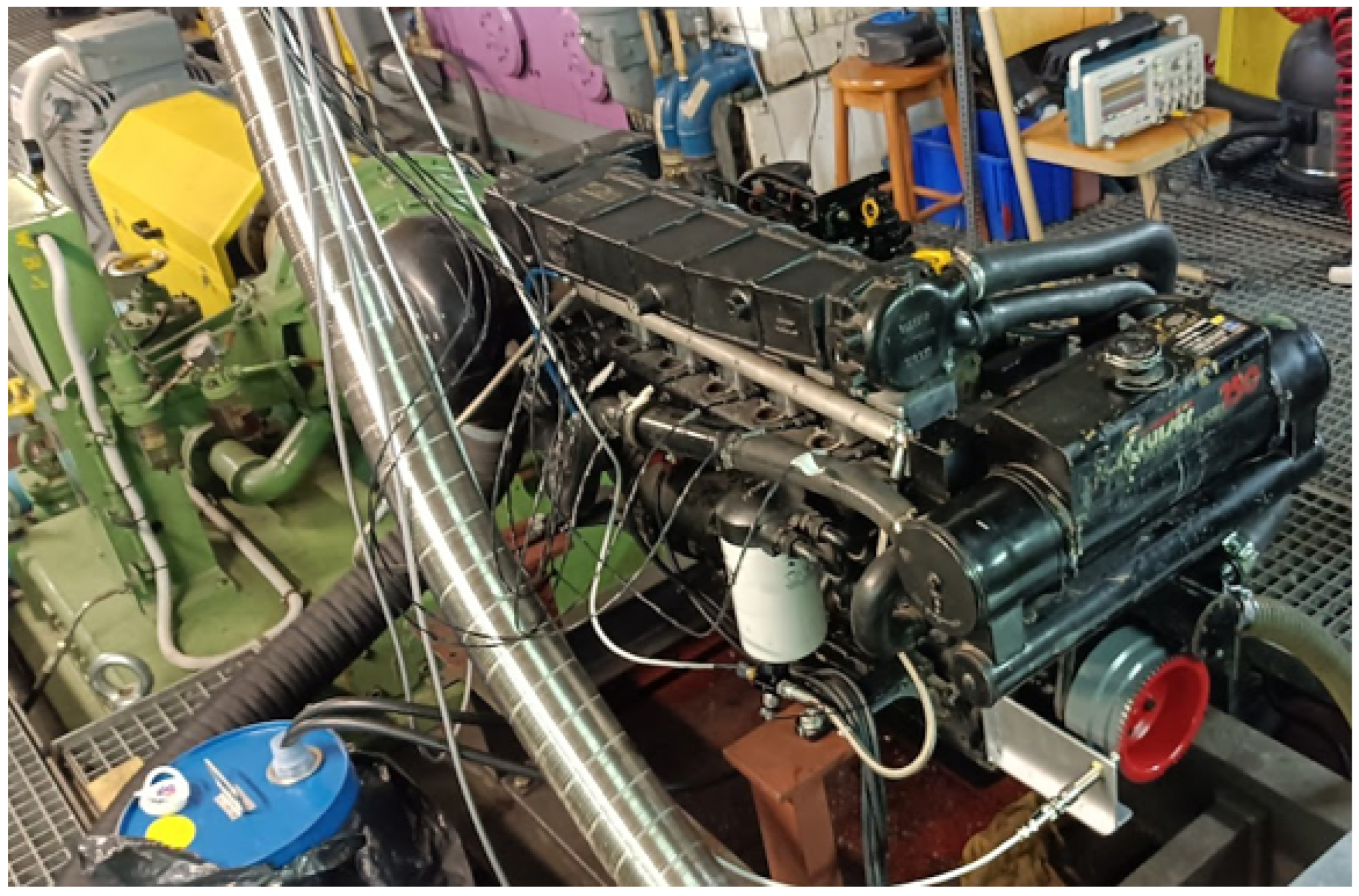
In this work, the data for calibrating the numerical models were derived from a conventional 4-stroke high-speed marine engine retrofitted for DMDF operation by installing low-pressure methanol injectors in the engine air path before the intake port of the cylinders [
29]. The technical specifications of the DMDF engine are presented in
Table 1. The installation of the methanol injectors involved raising the intercooler and placing six custom-made injector hubs between the intercooler and intake/exhaust manifold. The injected methanol formed a homogeneous mixture with the intake air. The reason for this is that methanol was not injected directly into the intake port but rather into the intake air stream. Hence, to be inserted into the mixture, it had to be dispersed in the intake air either directly or indirectly via evaporation, for the methanol formed a film on the intake pipe walls. Furthermore, because of the engine swirl, the homogeneity of the mixture should be sufficient to be considered fully premixed. Finally, the CFD results, in which we assumed that the mixture was completely homogeneous, matched well with the experimental data. Bosch EV14 injectors were chosen for methanol injections due to their widespread use in gasoline port injection within the automotive sector, as well as their compatibility with methanol. A low-pressure common rail system was utilized to supply methanol to the injectors, comprising a methanol-compatible fuel pump and a pressure regulator to maintain fuel pressure at 8 bar. All equipment and materials used for the new methanol fuel system are indicated or have been tested for methanol use to avoid problems such as corrosion. The control of the methanol fuel system is managed by a separate ECU manufactured by HEINZMANN GmbH & Co. KG, Schönau im Schwarzwald, Germany, while the original diesel system and its control unit remain unchanged. The new ECU controls the amount of methanol injected by adjusting the injection duration with respect to the methanol common rail pressure and injection quantity curve provided by the manufacturer.
An experimental setup was established at the Laboratory of Marine Engineering (LME) at the National Technical University of Athens (NTUA) to validate the engine by adapting the existing HIPPO-1 testbed infrastructure [
30]. The engine was coupled to an AVL-Zoellner hydraulic dynamometer rated for 1200 kW at 4000 rpm, with the opposing electric motor removed. Instrumentation integrated into the testbed included a wide-range linear NGK Smart
NOx sensor
positioned downstream of the exhaust gas cooling unit, two ABB Coriolis flow meters integrated into the diesel fuel supply and return circuits, a magnetic Micro-Epsilon sensor for turbocharger rotor speed monitoring, and torque and rotational speed sensors. Furthermore, other sensors were installed to better monitor the engine, i.e., methanol consumption was determined by real-time weight monitoring of the fuel tank using a Kistler load cell, and combustion analysis was enabled by a Kistler 6052C pressure transducer installed in the glow plug port and synchronized with a crank angle encoder. The existing engine sensors incorporated into the existing data acquisition system were intake manifold pressure/temperature, coolant temperature, diesel injector valve lift, and pump timing/quantity. Data acquisition was managed by two systems: a dSpace DS1103 controller integrated into MATLAB/Simulink that oversees testbed operations at 1 kHz sampling and a National Instruments DAQ that captures high-frequency combustion signals at 50 kHz. Emissions were quantified using a portable Sigma 8000 analyzer installed in the exhaust stream, measuring concentrations of
,
,
, formaldehyde (
), and methanol (
).
Figure 1 and
Figure 2 depict the instrumentation layout and testbed configuration.
The DMDF engine testbed was utilized to perform experiments and extract the required data for calibrating the models. More specifically, the engine was tested in both diesel and dual-fuel modes for a speed range of 1000 to 3000 rpm. The load of the water brake was adjusted accordingly to be similar to that of a small craft propeller suitable for the size of the engine being examined, with a maximum torque of 300 Nm. During the experiments, for each measured operating point, the engine was first tested in diesel mode by adjusting the diesel throttle accordingly. After the measurement was completed, the throttle was reduced, and methanol was injected. The amount of methanol injected was continuously increased until the operating point was reached again. Then, the same measurements were conducted, and the process was repeated for higher MESRs. At each load point, before the measurement started, the engine remained in a steady-state condition for a small time period in an effort to minimize the effect of transients between the operating points. For each measured point, the combustion cycle was measured at least 100 times, and the mean values were taken into account. The maximum MESR reached during the experiments was 50% for safety reasons related to high cylinder pressures and possible misfire. The ranges of parameters under which the experiments were conducted are shown in
Table 2. The environmental conditions during the experiment were recorded and remained the same for all experiments. More specifically, the air temperature was 20 °C, the cooling water temperature was 15 °C, and the relative humidity was 30%.
4. Results
In this section, the results of the numerical parametric study are presented. In order to assess the potential of the retrofitted DMDF engine, a numerical simulation was conducted for a number of operational parameters. Specifically, the CFD combustion model was simulated for engine speeds of 1000–3500 rpm, MESRs up to 75%, injection timings of 20 to 5 BTDC, and equivalent fuel energy injected into the cylinder of 10 to 60 mg of diesel fuel per cycle. The temperature at the limits of the cylinder was estimated and adjusted accordingly using experimental data. The numerical model was simulated for 1552 scenarios, the parameters of which are shown in
Table 6. It should be noted that, in order to quantify the engine load, each point is characterized by the total fuel energy injected into the cylinder of both diesel and methanol in terms of equivalent diesel fuel.
As can be observed, the results for all the scenarios are extensive and difficult to depict analytically. Hence, for the purpose of this work, the analysis mainly focuses on the load conditions for a marine engine of this type, which are more common, i.e., low loads at low speeds and higher loads at high speeds. Finally, all results are taken into account to establish operational limits for the engine with respect to MESR and diesel injection timing.
4.1. Methodology
The evaluation of the numerical results was performed using the following methods. The key factor of the MESR characterizes the fraction of energy released by methanol, which is defined as
where
is the mass flow of each fuel,
is the lower heating value of the fuel, and
d and
m denote diesel and methanol fuel. Another important parameter that affects engine performance and emissions is combustion efficiency. This parameter is defined by the percentage of fuel energy released during combustion:
where
is the total chemical heat release within the cylinder. Pressure trace analysis is performed using the first appropriately formulated thermodynamic law for engine applications [
42]:
where
is the fuel combustion heat release of methanol and diesel,
is the heat absorbed by the cylinder boundaries,
is the angle of the crank,
P is the pressure in the cylinder,
V is the instantaneous volume of the cylinder, and
is the heat capacity ratio, which depends on the composition and temperature of the mixture. For this study,
was considered constant for the experimental results and equal to 1.35, according to standard practice for these engines. For the CFD study,
was calculated directly using the CFD code considering the composition of the mixture in the cylinder. To evaluate the propensity to knock during dual-fuel operation, the ringing intensity (RI) metric was calculated to quantify combustion instability, following the methodology described in [
17]:
where
is the maximum pressure rate,
is the maximum in-cylinder pressure, and
is the maximum in-cylinder temperature.
4.2. Combustion Characteristics
The combustion characteristics of the DMDF engine were evaluated through a detailed analysis of the results of numerical simulations, focusing mainly on the pressure profiles and several other key parameters, using the methodologies mentioned above, together with other parameters that are commonly used for the evaluation of engine combustion.
4.2.1. In-Cylinder Pressure
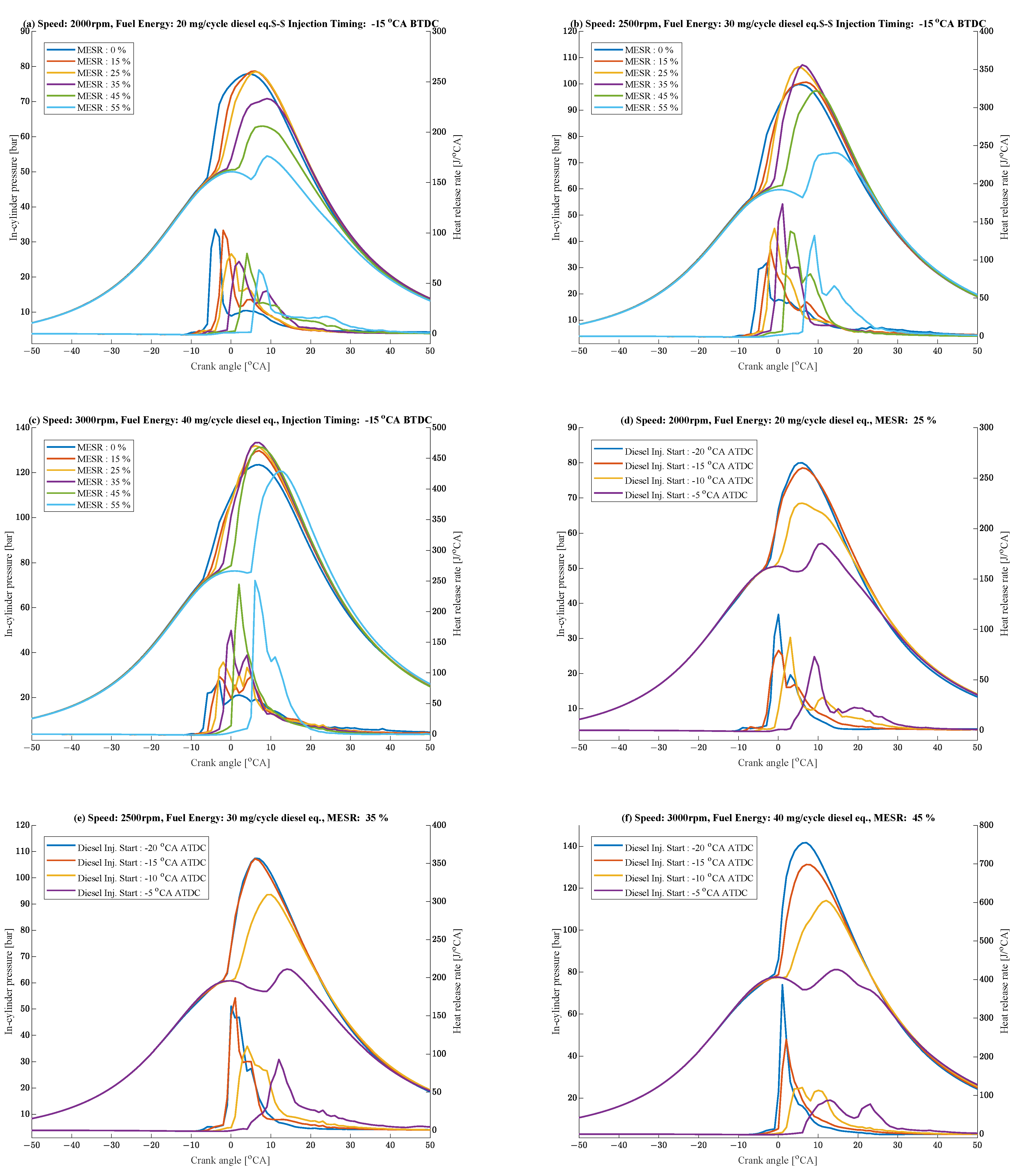
A group of in-cylinder pressure traces, along with the apparent heat release rate resulting from the numerical simulations, is shown in
Figure 6 for various engine speeds, loads, MESRs, and diesel injection timings. The impact of the MESR on engine combustion is depicted in
Figure 6a–c, where the pressure traces for three operational points at various MESRs are shown. The impact of diesel injection timing is shown in
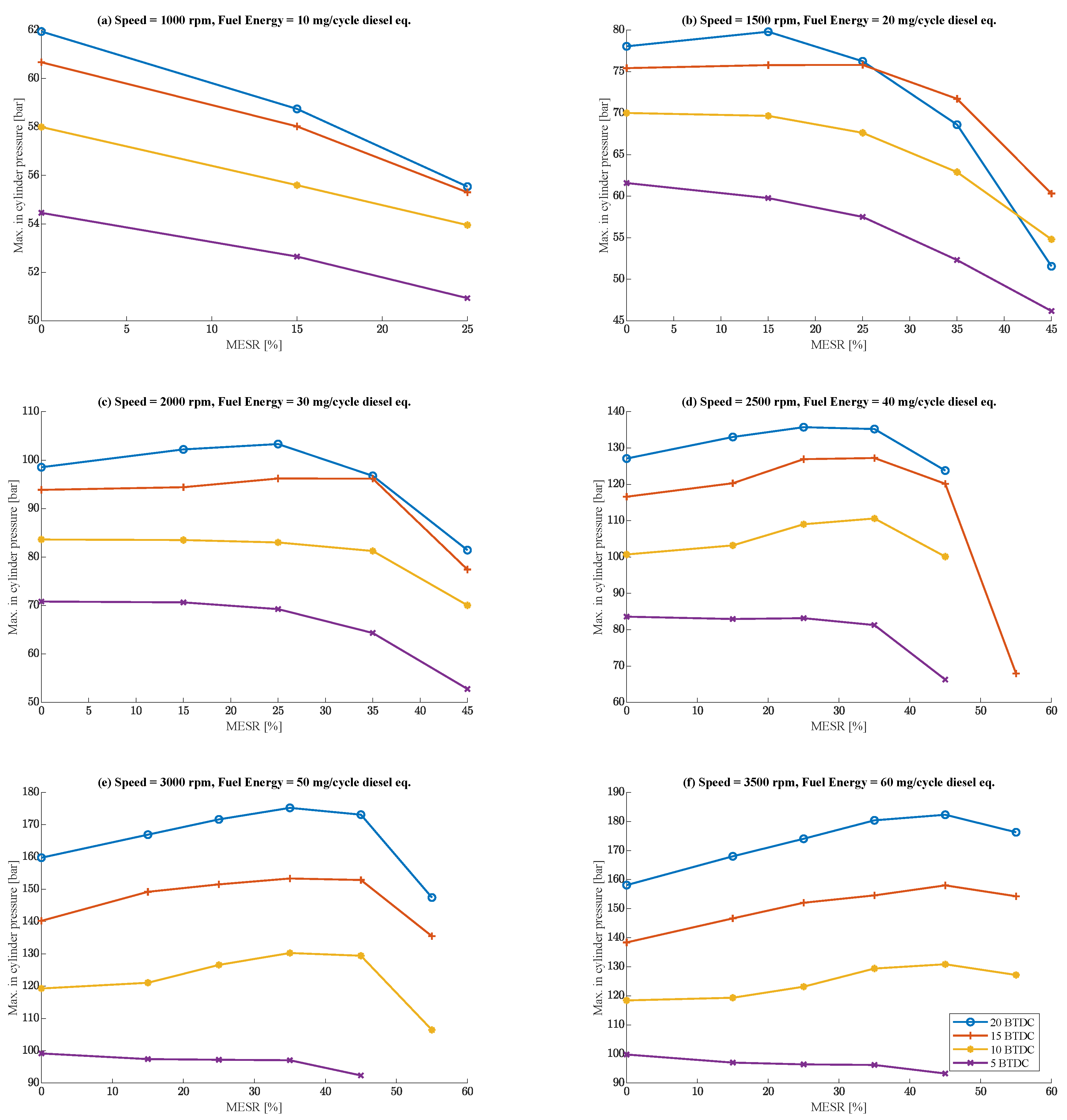
Figure 6d–f. Moreover, the peak in-cylinder pressure is shown in
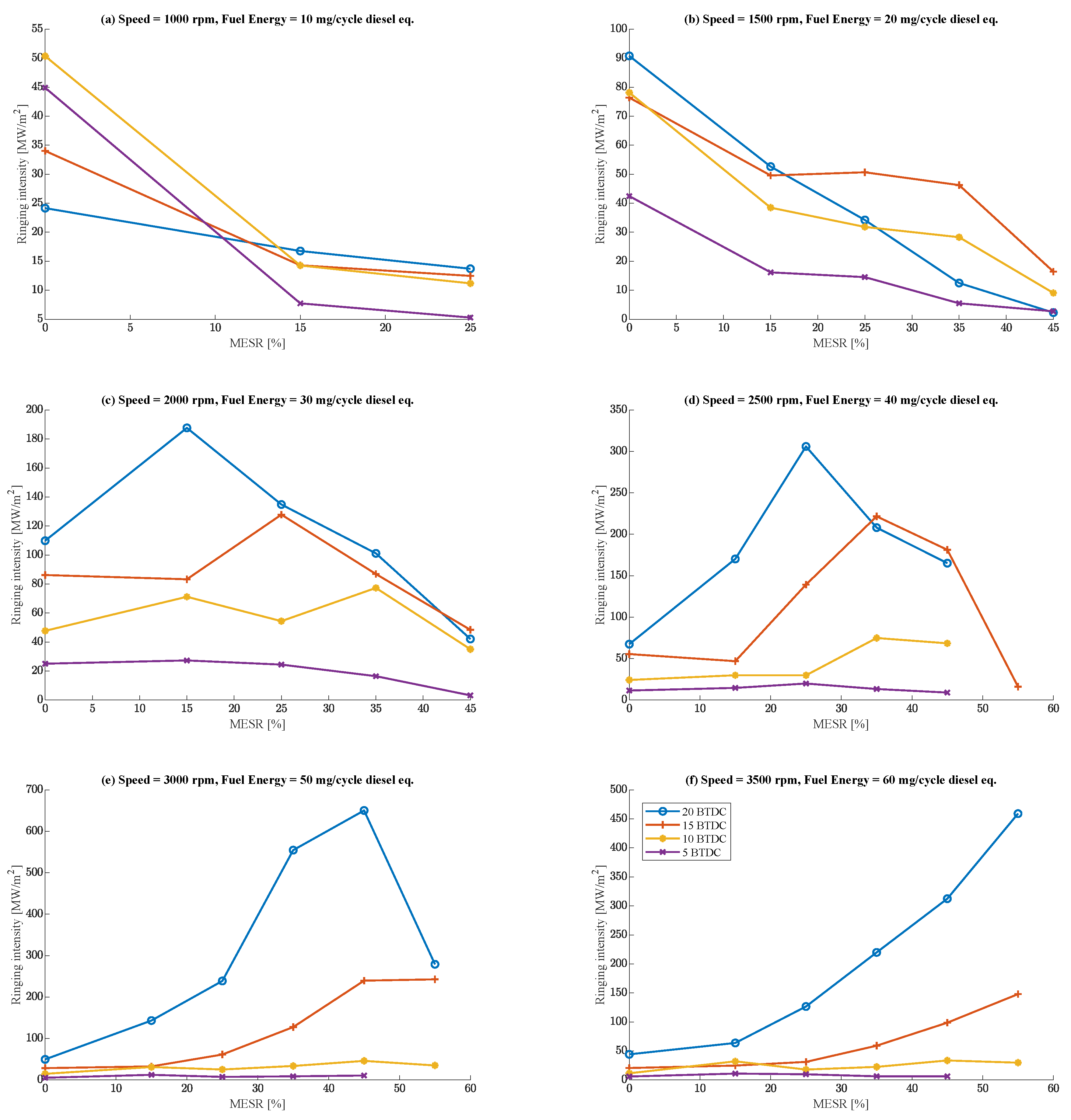
Figure 7, while the ringing intensity is shown in
Figure 8.
As shown, the primary effect of methanol is the prolonged ignition delay. Depending on the ignition timing with respect to the top dead center (TDC) point, the maximum in-cylinder pressure is reduced if the ignition occurs far from the TDC, while it increases if it is closer. At lower loads, the maximum in-cylinder pressure is reduced as the MESR increases. At medium loads, the maximum pressure initially increases and peaks at an MESR of around 25–40%. At higher loads, the maximum in-cylinder pressure continues to increase. On the other hand, advancing injection timing causes ignition and combustion to begin earlier, closer to the TDC, resulting in higher in-cylinder pressure. Furthermore, the heat release rate (HRR) indicates that when the injection timing advances, the combustion process occurs around the TDC due to the decreased cylinder volume and the resulting higher in-cylinder pressure, leading to higher HHRs.
The maximum in-cylinder pressure is an important parameter, as there are structural limitations to the engine. For the engine used in this work, the maximum in-cylinder pressure is around 160 bar. As can be seen from the results, at lower loads, the maximum in-cylinder pressure decreases as the MESR increases, while at medium or higher loads, the maximum pressure remains at the same level or slightly increases. The reason for this behavior is explained by the fact that, at lower loads, the necessary conditions for the ignition of the methanol–air mixture are not met for the whole cylinder, leading to partial burning of the mixture and, consequently, lower HRRs. At higher loads, the increase in pressure and temperature due to diesel autoignition leads to the simultaneous ignition of the entire mixture. On the other hand, advancing diesel injection timing leads to an increase in the maximum in-cylinder pressure across all scenarios. This can be explained by the fact that there is more time for the diesel fuel to premix with the intake charge before ignition. Hence, when the mixture ignites, larger amounts of diesel and methanol fuel ignite concurrently, leading to increased pressure change rates. At higher loads, by combining these two factors, the maximum pressure exceeds the maximum allowable limits for the engine, even for small MESRs. Hence, to utilize methanol at higher loads, the diesel injection timing advance must be reduced.
The previous conclusions can be extracted from the ringing intensity results. As depicted, the ringing intensity decreases with increased MESRs at lower and medium loads, while it increases significantly at higher loads. That indicates that combustion becomes unstable at high loads and higher MESRs, especially when combined with advancing diesel injection timings.
4.2.2. Ignition Delay and Combustion Duration
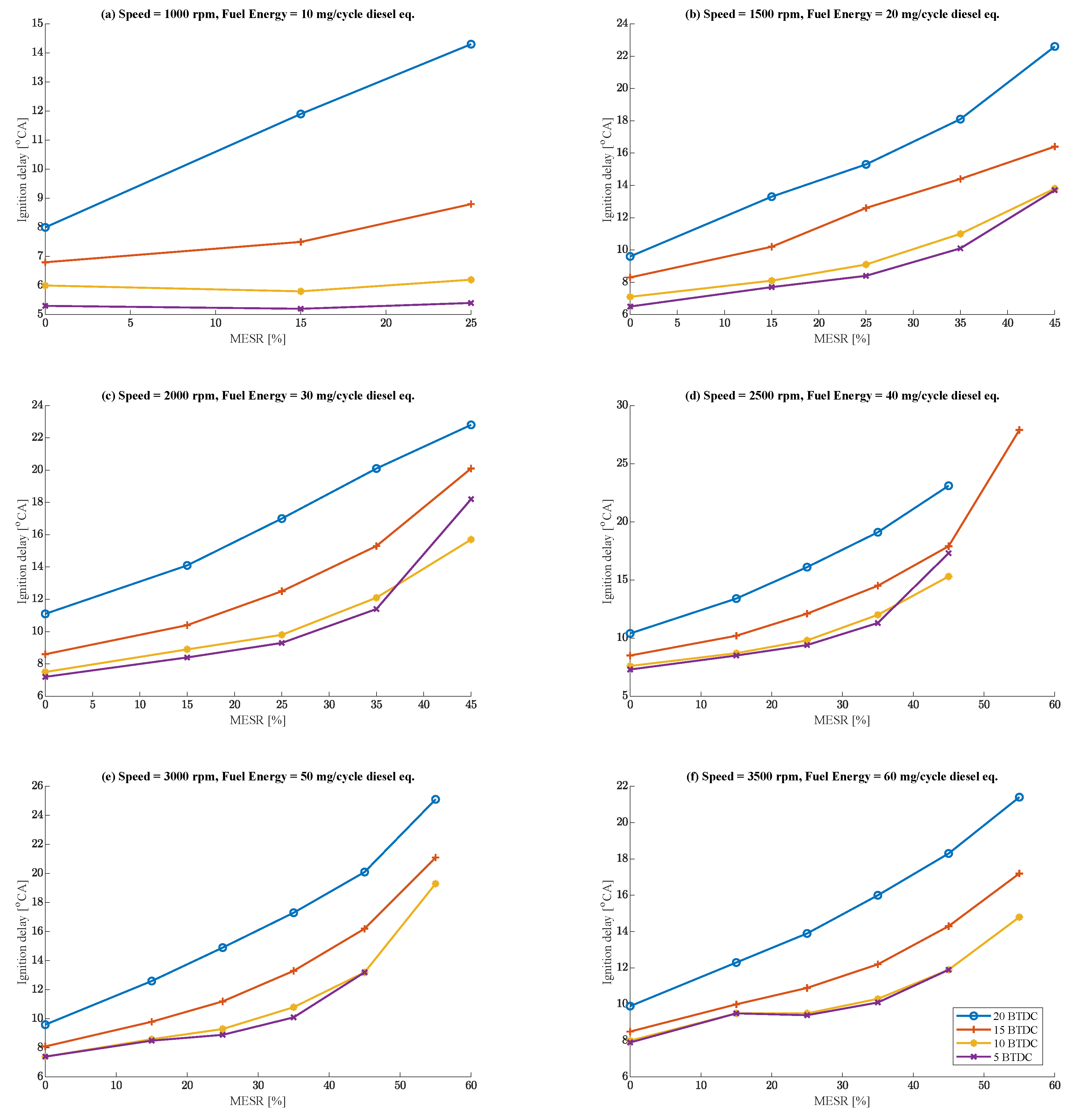
The impact of the MESR and diesel injection timing on the ignition delay and combustion duration is shown in
Figure 9. In the present work, the ignition delay is considered the time from the start of injection to the point where the chemical heat release rate begins. As depicted, the ignition delay increases with increased MESRs. The major factor contributing to this result is the large latent heat of the evaporation of methanol, which results in lower intake and compression temperatures, thus reducing the reactivity of the diesel fuel when injected. The mechanistic study by [
17] further identified that methanol mediates the conversion of active hydroxyl radicals to less reactive hydrogen peroxide species during the low-temperature oxidation phase of diesel. This leads to a general reduction in the reactivity of the mixture, further increasing the ignition delay of diesel. Regarding diesel injection timing advances, the results show an increase in ignition delay, which can be attributed to the fact that fuel injection occurs far from the TDC, where pressure and temperature are lower; therefore, it is not favorable to diesel ignition.
Figure 10 depicts the combustion duration. In the present work, the combustion duration is considered the interval during which 10% to 90% (CA10–CA90) of fuel energy is released. As depicted, the MESR generally reduces combustion duration, while the diesel injection timing advance increases the combustion duration. The reason for this is that methanol is introduced into the cylinder via port injection, and, as a result, forms a homogeneous mixture with the intake air. The combustion of this mixture is considered to be conducted in a premixed manner, which is generally faster than diffusion combustion. This also explains the impact of advancing diesel injection timing, where diesel fuel does not ignite immediately but rather mixes with the intake charge to form a premixed mixture. For lower loads, it should be noted that the combustion duration increases with increasing MESRs. This indicates that the mixture does not ignite concurrently in all regions but rather in the regions closest to the diesel injection spray before spreading to other regions of the cylinder. This can be seen in the above-mentioned pressure diagrams, where the initial HHR peak is relatively small and is followed by a secondary peak, indicating a long-tail combustion.
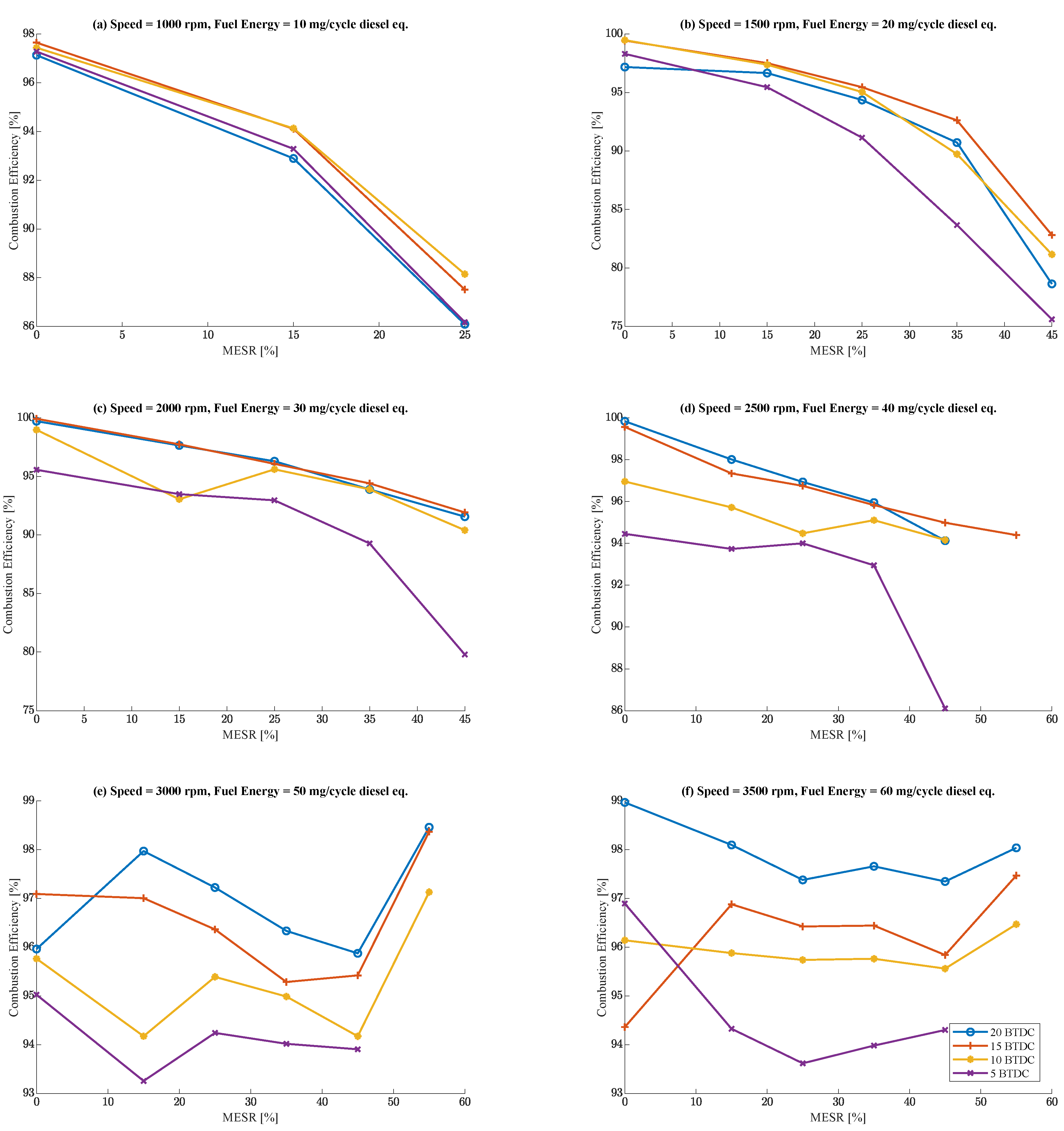
4.2.3. Combustion Efficiency
Figure 11 shows the combustion efficiency with respect to the MESR and diesel injection timing. This parameter is of great importance because it indicates the ability of the engine to combust all of the injected fuel and is directly related to engine performance and unregulated emissions. As expected, for lower loads, an increased MESR results in a decreased combustion efficiency. The primary reason for this is that at lower loads, the necessary conditions that can support ignition and combustion of the air methanol mixture are not present. Hence, the mixture initially ignites around the diesel injection spray, but it fails to ignite in regions where the temperature is not high enough. If the MESR is further increased, combustion efficiency decreases further until there is no combustion at all, leading to engine misfire. At medium and higher loads, the combustion efficiency decreases slightly or remains within acceptable levels, as the previous situation is alleviated, and the combustion efficiency consistently exceeds 90–95%. Injection advance has a positive impact on most loads because of the premixed combustion it promotes, except at lower loads, where the cylinder conditions do not favor premixed ignition.
4.3. Emissions
Engine emissions are one of the most important parameters for engine operation since strict limits are imposed. The analyses focus on both regulated and unregulated emissions.
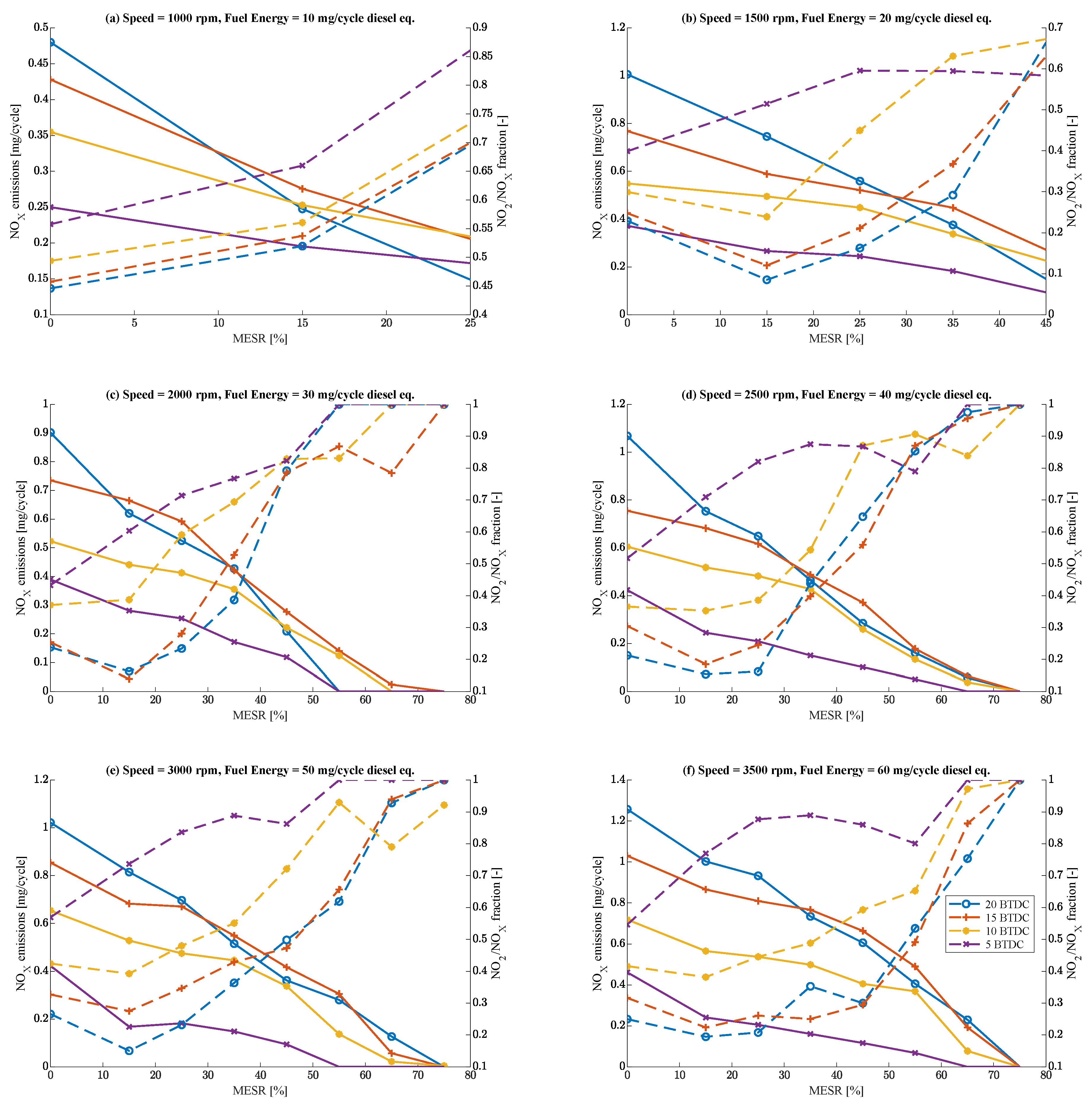
4.3.1. NOx Emissions
The resulting
emissions, together with the proportion of
in the total
, are shown in
Figure 12. The most significant observation is that
emissions greatly reduced with the introduction of methanol. The main reason for this is that within the cylinder, pressure and temperature are effectively reduced due to the large latent heat of evaporation of the methanol. Additionally, considering the extended Zeldovich [
31] mechanism for the thermal formation of
, temperature is the main factor contributing to its creation. In addition, advancing diesel injection timing has been shown to increase the formation of
. As explained previously, advancing diesel injection timing increases the maximum cylinder pressure and, consequently, temperature; therefore, the thermal formation of
is enhanced. In terms of the fraction of
, the MESR has been shown to increase its formation. In traditional diesel configurations, the main component of
emissions is
. In the DMDF case, the formation of
increases because methanol oxidizes and creates hydroperoxyl radicals, which favor the formation of
[
12].
4.3.2. Soot Emissions
Soot emissions are shown in
Figure 13. As can be seen, increasing the MESR greatly reduced the formation of soot emissions for all the load points. The main reason for this is that methanol does not contain a C-C bond, which is the main attribute of soot formation during combustion. Furthermore, most of the heat release is produced as the mixture is combusted by a premixed flame rather than diffusion, which also reduces the formation of soot. The final reason is also the main explanation for the decrease in soot emissions as injection timing advances since, as mentioned before, advancing injection timing favors premixed combustion.
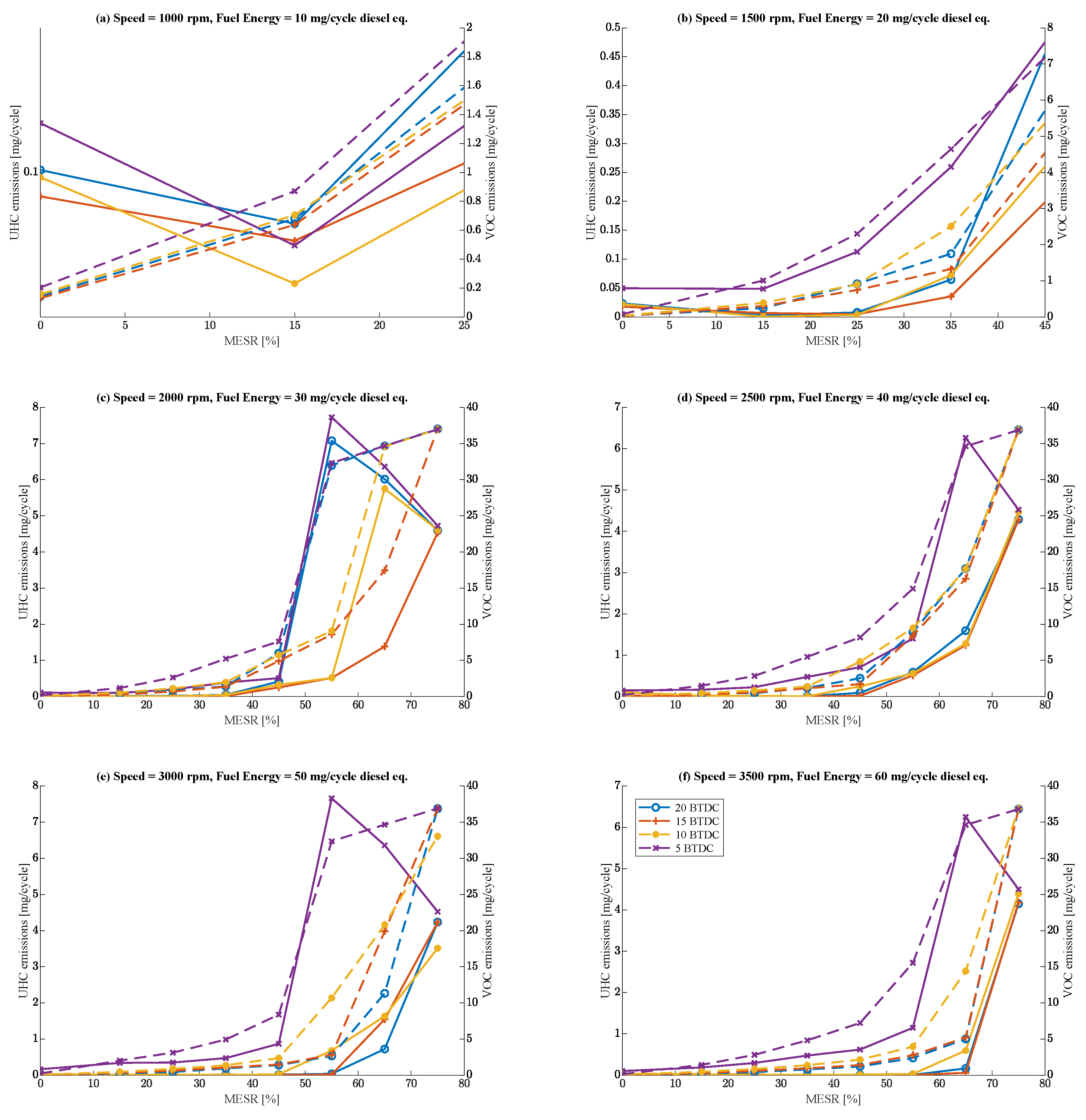
4.3.3. Unregulated Emissions
While
and soot emissions are examined most frequently in studies related to diesel engines, the literature suggests that DMDF engines greatly increase the production of unregulated emissions. The numerical results related to these emissions are shown in
Figure 14. These emissions are separated into two groups. The first group refers to compounds that are formulated with atoms of
C and
H and are commonly known as unburned hydrocarbons. The second group, which is referred to as Volatile Organic Compounds (VOC),is formulated by compounds that include
C,
H,
O, and
N atoms. The separation of these groups was conducted to clarify the exact nature of the compounds commonly emitted by a DMDF engine. As can be seen in the figures, the increase in the MESR heavily increases the production of unregulated emissions up to 100 times. However, these emissions are made up mainly of volatile organic compounds, while other
emissions also increase but are much lower. The reason for this is the incomplete combustion of a portion of the methanol air mixture. It should be noted that organic volatile compounds are generally toxic to humans. In terms of the composition of these compounds, the numerical model indicates that they are made up mainly of methanol, formaldehyde, and carbon monoxide. However, it should be noted that although the experimental measurements agree with the total measurements of these compounds, the dominant compounds are formaldehyde and carbon monoxide, rather than methanol. This can be explained by the fact that unburned methanol is further oxidized in the exhaust plenum of the engine.
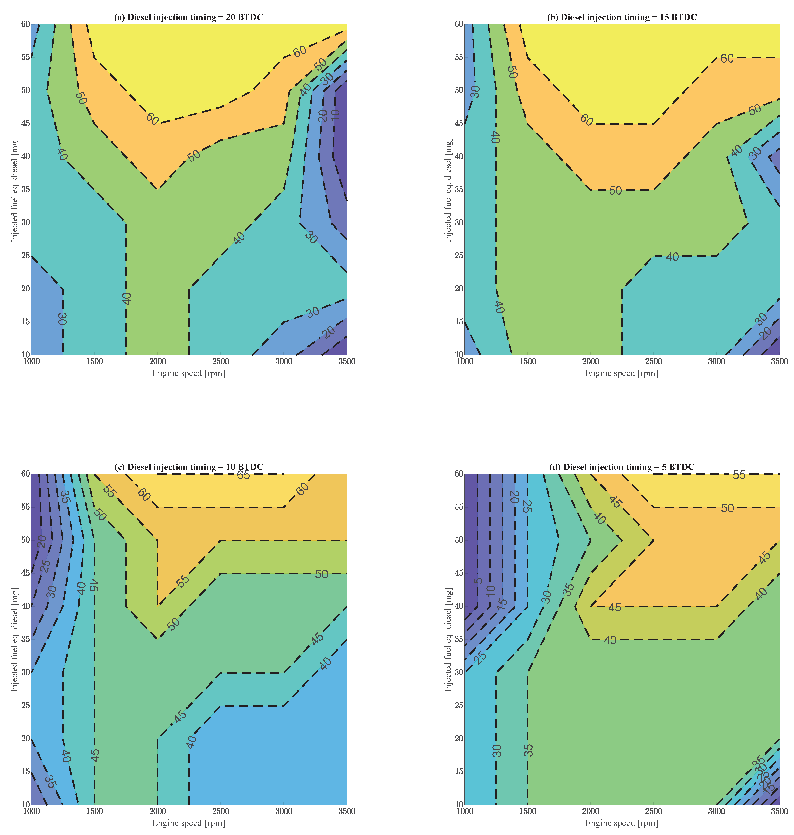
4.4. DMDF Operational Limits
An important aspect of the use of DMDF engines in the maritime industry is the definition of operational limits for these retrofitted engines. As reported in [
16], these engines have operational limits with respect to the MESR associated with the combustion characteristics of the DMDF mode. In particular, at lower and medium loads, the increase in the MESR could lead to partial combustion of the mixture and even misfire if the in-cylinder conditions required for methanol autoignition are not met. This leads to reduced engine performance and thermal efficiency. At higher loads, an increased MESR usually leads to increased cylinder pressure, violent combustion, or even autoignition of the methanol before the diesel injection, i.e., knock, which can potentially harm the engine’s structural integrity. Taking all these factors into account, the maximum MESR for the different injection timings examined was estimated from the numerical results and is depicted in
Figure 15. To define the limits, the engine was assumed to operate with a combustion efficiency of at least 80% and a maximum cylinder pressure of less than 160 bar. The results are plotted in comparison to equivalent injected diesel fuel with the same chemical energy as both diesel and methanol at DMDF combustion.
As shown in the figure, the maximum MESR was achieved for medium loads and speeds. At lower speeds, the MESR cannot be increased due to limitations related to partial combustion of the mixture and possible misfires. However, at higher speeds and loads, the MESR is limited by the maximum in-cylinder pressure, as a high percentage of methanol leads to violent combustion. In the present study, no methanol knocking was observed before diesel injection. Regarding diesel injection timing, it should be noted that operational limits can be adjusted by modifying diesel injection timing, indicating that advancing injection timing can extend operational limits at lower loads and speeds, while retarding injection timing injection is preferable for higher loads. Finally, it should be noted that these limits can be altered if further modifications are made to the engine, e.g., by adjusting the intercooler capacity, as suggested by numerical data.
5. Discussion and Conclusions
In the present work, a parametric numerical investigation of a retrofitted DMDF engine was conducted using an established CFD combustion model, which was calibrated using experimental data from an actual DMDF engine testbed. The intake cylinder conditions for the simulations were estimated using semi-physical and data-driven models for the engine air path and the injection duration. The results of the numerical simulation revealed the effects of the methanol ratio and the timing of the advance of diesel injection on combustion, performance, and emissions. Furthermore, considering the maximum allowable in-cylinder pressure and the minimum required combustion efficiency of 80%, the maximum MESRs for each diesel injection timing advance examined were estimated from the results.
More specifically, regarding the combustion characteristics, the parametric study revealed that the ignition delay increased because of the high latent heat of evaporation, which lowered the in-cylinder temperature, and the presence of active hydroxyl radicals, which interfered with the autoignition process. However, the combustion duration was shortened since a larger portion of the combustion was premixed. Moreover, at low loads, the maximum cylinder pressure decreased with an elevated MESR because of the partial combustion of methanol. At medium to high loads, steady or marginally increasing pressures were observed. In addition, the combustion efficiency decreased at low loads due to the partial combustion of methanol, although it remained around 90% at medium and higher loads. These results indicate that the combustion phasing has been altered and hence, the injection timing should be adjusted to achieve optimum combustion phasing, considering combustion stability and performance. More specifically, at lower to medium loads, an advance in diesel injection beyond 15 °CA compensated for the increased ignition delay due to high methanol ratios, resulting in ignition at the crank angles before the TDC. This led to higher portions of premixed combustion, which generally indicates higher combustion efficiencies. At higher loads, a high MESR combined with increased advanced timing may result in unacceptably high cylinder pressures that may potentially lead to unstable combustion and damage the engine, as the ringing intensity metric suggests. In this case, retarded injection timing near TDC could result in a substantial decrease in cylinder pressures, while combustion efficiency remains above 93 to 95%. Taking into account these two facts, for medium to higher loads, it is suggested that the injection advance be reduced, even for limited MESRs. If diesel injection timing cannot be adjusted, it is suggested that the maximum MESR be limited for low and high loads to avoid reduced combustion efficiency and unstable combustion. It should be noted that these results are highly dependent on the intake cylinder conditions, and alterations, for example, at the intercooler for reduced cooling capacity when the MESR is high or increased compression ratios could compensate for the aforementioned effects.
Regarding emissions, the MESR reduced thermal by decreasing peak temperatures through evaporative cooling. Moreover, the percentage increased as a result of hydroperoxyl radicals produced from methanol. Advancing diesel injection timing increased emissions by increasing combustion temperatures. Soot emissions decreased markedly with the MESR, mainly because of the absence of C-C bonds in methanol and the predominance of premixed combustion. Advancing diesel injection timing also significantly reduced soot emissions through improved premixing. However, for unregulated emissions, increased methanol ratios increased unburned hydrocarbons by up to 100 times, associated with partial oxidation of methanol. These emissions mainly consisted of volatile organic compounds, which are toxic to humans. As seen in the results, these emissions spiked when the MESR exceeded values of 40 to 50%, resulting in concentrations four to five times higher, especially for delayed injection timings. Hence, for the utilization of these engines with larger MESRs, other solutions should be considered, including after-treatment units. It should be noted that these emissions are not officially regulated by authorities for marine engines, a matter that should be reconsidered since they are the main emission product after for high MESRs.
Another point worth mentioning is that the results indicate that the increase in the methanol ratio contributed to the simultaneous decrease in and soot emissions, while the performance of the engine was reduced. However, unregulated emissions increased greatly. Hence, the traditional trade-off for and soot emissions vanished, and new trade-offs for regulated, unregulated emissions, and performance arose, which must be considered during operation. The most balanced option with respect to the results of this study appears to favor high MESRs around 50% along with medium advance injection times at medium loads, which can result in high efficiency and low overall emissions. At low loads, the optimal arrangement appears to be a low MESR of below 30% and advanced injection timings due to misfire and reduced efficiency. However, at higher loads, the MESR should not exceed 40%, while injection timing should be delayed, as combustion after this point seems to be unstable, and unregulated emissions greatly increase. In terms of operational limitations, for lower and medium loads with respect to the MESR, limits are defined by the risk of misfire and the combustion efficiencies that occur below 80%. At higher loads, structural considerations limit the MESR due to the dangers of violent combustion and knocking. Advanced timing increases low-load MESR thresholds but requires retardation at elevated loads to alleviate pressure surges.
It is evident that the performance and emissions of these kinds of engines are heavily dependent on the optimization of the injection timing and methanol ratio, as this study revealed, while new challenges, e.g., increased unregulated emissions, must be addressed in order to fully utilize the potential of these engines. Future studies should investigate other parameters that can affect engine performance, e.g., adjusting intercooler capacity with respect to the MESR and the impact of the compression ratio, especially for low-load dual-fuel combustion. Furthermore, the examination of after-treatment units for these types of engines should be considered to alleviate the problem of increased unregulated emissions.


