Abstract
The tensile armor layer plays a crucial role in offshore flexible pipelines, primarily bearing axial tensile loads. However, during installation and operation, it may experience compressive forces, leading to a risk of lateral buckling, which is further intensified by manufacturing deviations in the steel strips. This study introduces a method to quantify these deviations based on the circumferential length change in defect segments in helically wound steel strips. A deviation model is established and analyzed using Abaqus finite element simulations to evaluate the impact of helical angles and deviation severity on the critical lateral buckling load. The results reveal that as the deviation severity increases, the critical buckling load significantly decreases, with reductions of up to 65% for small helical angles. Additionally, the rapid rise in bending moment at the defect location is identified as the primary cause of lateral buckling initiation.
1. Introduction
Flexible risers are primarily used to connect subsea wellheads to floating platforms at the water’s surface, transmitting oil and gas resources extracted from the seabed to the surface. These risers are composite structures formed by unbonded combinations of multiple functional layers, with each layer designed to bear specific loads. A key feature of flexible pipes is their bending stiffness, which is significantly lower than their tensile stiffness. Compared to rigid pipes, this characteristic makes flexible pipes more suitable for use with offshore floating facilities for collecting subsea resources. A typical cross-sectional illustration of this composite structure is shown in Figure 1, where the tensile armor layer is designed to bear external tensile loads during the manufacturing, handling, transportation, installation, and operation of the pipeline. However, during the above process, especially in empty pipes during the installation process and in grounded sections of pipelines during service [1], the tensile armor layer may sometimes be subjected to axial compression, which is a non-design load, causing the steel strips to buckle, including radial buckling (‘birdcage’), as shown on the left of Figure 2, and lateral buckling, as shown on the right of Figure 2.
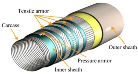
Figure 1.
Flexible pipe structure composition diagram.
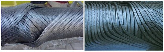
Figure 2.
Radial buckling (birdcage) and lateral buckling of marine flexible pipelines.
Lateral buckling of the armor layer involves buckling behavior of the steel strips within the plane of curvature, which can lead to plastic deformation of the layer and compromise the integrity of the pipeline, thus being considered a severe failure mode [2]. Since there are no preventive measures for lateral buckling, unlike the anti-birdcage strips used for radial buckling, studying the factors influencing lateral buckling of the tensile armor layer is of paramount importance.
Many scholars have conducted theoretical analyses on the lateral buckling resistance of armor steel strips. Østergaard et al. [3] modeled a single armor wire as a slender curved beam embedded in a frictionless cylindrical surface bent into a ring. To trigger the lateral buckling failure mode, lateral curvature was introduced as a defect into the sixth-order differential equation used to determine the equilibrium state of the armor wire. Li et al. [4] developed an analytical model to assess the equilibrium state of a single armor wire on a frictionless circular surface, using a parameter perturbation method to determine the buckling limit eigenvalue problem, which resulted in periodic buckling consistent with the estimated buckling limit. Sævik and Thorsen [5] provided a linear differential equation for the lateral stability of armor steel strips under frictionless conditions, obtaining a lower bound for the lateral buckling resistance load. Tan et al. [6] proposed an analytical model based on the total strain energy method, which could predict the basic characteristics of both lateral and radial birdcage buckling behavior in helical tensile steel wires. This model was partially calibrated using DIP test results.
In addition, many researchers have used finite element simulations to study the lateral stability of armor steel strips. Sævik and Ji [7] developed a finite element model for armor steel strips under cyclic compressive and bending loads, using yield stress as the failure criterion. They found a complete correlation between the model behavior and experimental data. Sævik and Thorsen [8] discovered through finite element analysis that armor wires under cyclic bending could gradually slide laterally, and when the accumulated lateral curvature became large enough, the lateral buckling resistance of the steel strip significantly decreased. Caleyron et al. [9] developed a finite element model that leveraged geometric and load cycles to reduce model length and used it to investigate the risk of lateral buckling of tensile armor or pipeline collapse. Ye et al. [10] applied the Repeated Unit Cell (RUC) modeling technique to study the lateral buckling capacity of flexible risers and discussed the gap distribution between the circular positions of tensile armor wires.
In terms of experimental analysis, Lu et al. [11] designed a device to analyze the axial load of steel wires, recording the time history of the overall structural configuration of the helically wound steel wire. They obtained the critical buckling load as the compressive displacement increased and analyzed the strain state at the critical location, explaining the birdcage buckling mechanism of helically wound steel wires. Favaro Borges et al. [12] conducted full-scale compression experiments on two sizes of flexible risers, comparing the experimental data with finite element model results to analyze the relationship between compressive loads and defect sizes that led to radial instability and reduced pipeline stiffness. To study the mechanism of lateral instability in flexible pipes and to calibrate and validate the proposed analytical models, Li et al. [13] conducted bending compression tests on a 6-inch flexible riser and a 6-inch water injection flexible flowline in the NEO/COPPE laboratory, where significant lateral buckling behavior was observed after the experiments.
Through theoretical, numerical, and experimental studies, researchers have identified numerous factors that influence the lateral buckling stability of armor wires. It was found that the inner armor layer is more prone to lateral buckling than the outer layer, and under wet conditions, the absence of frictional constraints further lowers the critical load for lateral buckling [14,15,16]. Studies have also revealed that the lateral buckling resistance of armor steel strips is not only related to the curvature radius and bending radius of the surface on which the steel strip is located but also to the cross-sectional constants and helix angles of the steel strip itself [13,17,18]. Anti-buckling strips have a significant impact on the lateral buckling process of steel strips, and the smaller the installation angle of the strips, the stronger the resistance to lateral buckling [19].
It can be seen that current studies on the lateral buckling of armored steel strips rarely consider the influence of in-surface geometric deviations on their axial compressive load-bearing stability. In this paper, a finite element model is established for the lateral buckling of tensile armor steel strips with geometric deviation defects caused by manufacturing imperfections under axial compression in wet annulus conditions. The effect of such defects on reducing the critical load for lateral buckling is analyzed. By comparing the results with both theoretical and numerical data, the validity of the model is verified, providing valuable insights for improving the design of flexible pipe armor wires against lateral instability.
2. Geometric Equation of a Single Armor Wire
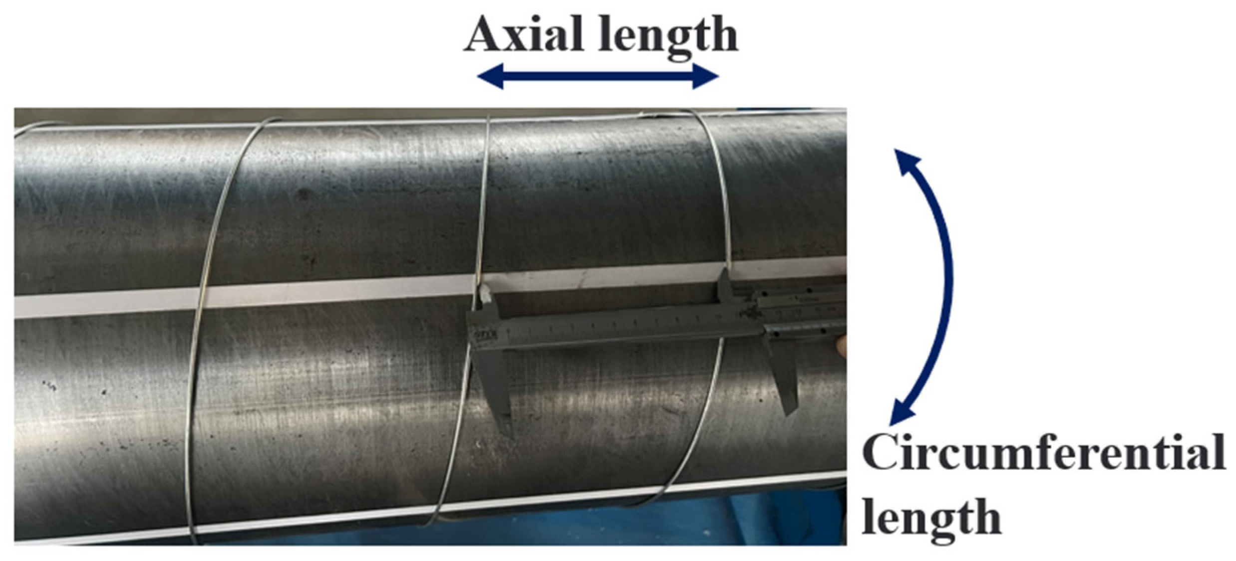
This section presents a method to quantify the degree of deviation of an armor wire from its ideal path. The reasons for the deviation of steel strips from their perfect geometric position may be due to errors introduced during manufacturing [20] (Figure 3) or repeated bending of the pipeline during service [8]. Manufacturing errors can be caused by fluctuations in processing tension, which affect the balance of the manufacturing process, leading to deviations in the positional accuracy of the steel strips. Ultimately, this results in uneven distribution of the steel strips within the same tensile armor layer.

Figure 3.
Measurement of deviation of steel strip after spiral winding [20].
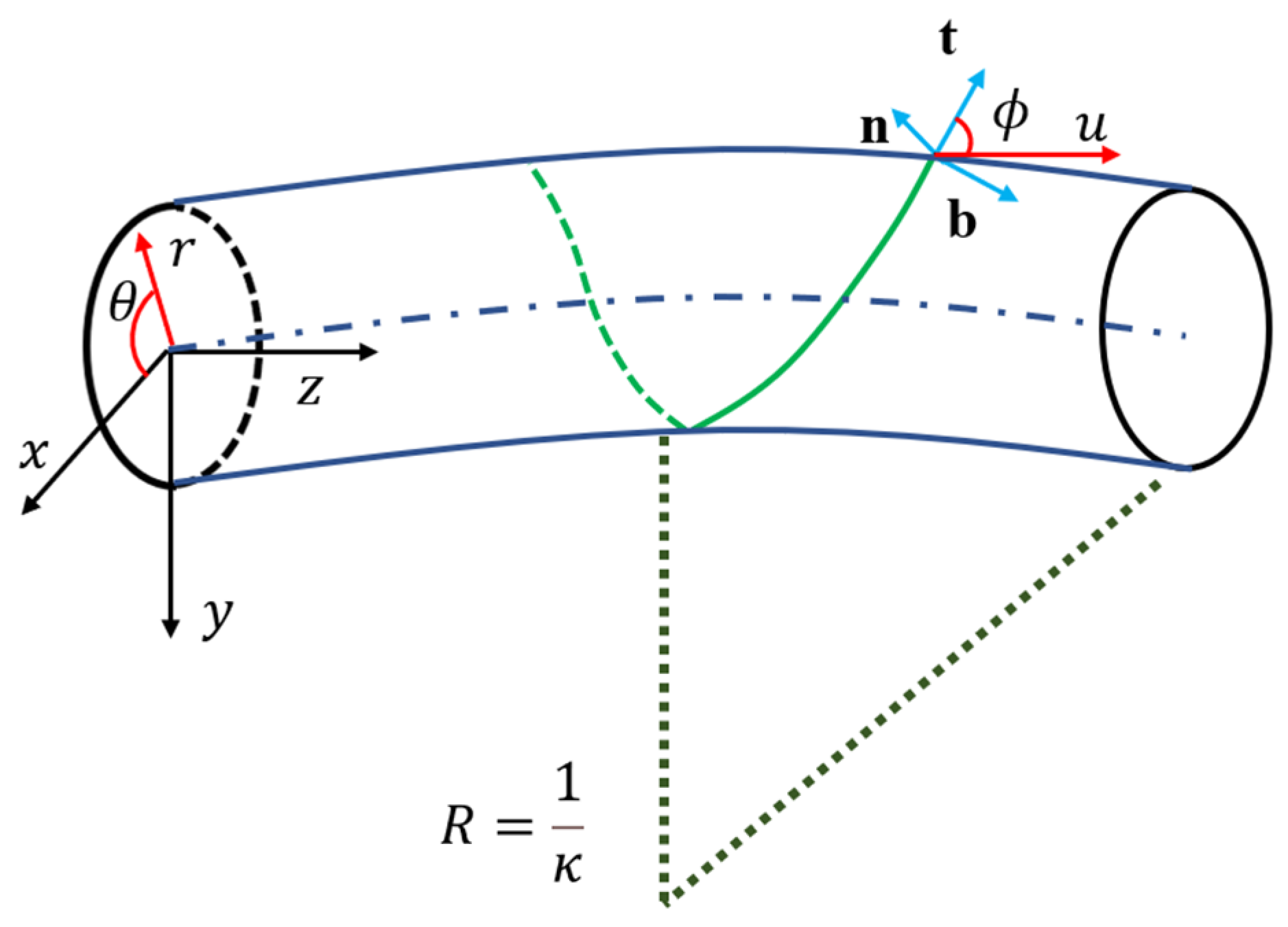
2.1. Curve Equation on a Torus
As shown in Figure 4, the surface of the armor layer can be viewed as a toroidal surface with a sectional radius and a curvature radius in the axial direction (with curvature ). The surface coordinates of this toroidal surface, parameterized using the and coordinate system, can be expressed as follows:

Figure 4.
Wire geometry and coordinate system.
A single armor wire is considered a directed curve that always lies on the surface. By assuming a relationship between and , the specific expression of the armor wire can be derived. The armor wire is then parameterized by arc length, represented by the parameter s. A set of orthogonal vectors is used to describe the tangent direction, normal direction, and binormal direction at a point on the curve.
where the vectors and represent the surface derivatives with respect to the toroidal coordinates.
Subsequently, referencing the definition of curves on surfaces from [18], the tangent direction of the curve can be rewritten as follows:
According to Equation (1), the norms of and can be calculated as follows:
Further, by comparing Equations (2) and (5), the following can be derived:
2.2. Curvature Components of Armor Wire
After establishing the orthogonal vector set at each point on the curve within the toroidal surface, the curvature components of the steel strip are needed to describe the deviation defect. The expression for the curvature components can be derived by taking the first derivative of the vector set with respect to the arc length of the curve. The Darboux frame, based on the Frenet equations, can be written as follows:
where , , and represent the geodesic curvature, normal curvature, and torsion, respectively.
The curvature components can be determined by the following equation:
By substituting Equations (1)–(4) into Equations (11)–(13), the curvature components of the curve can be obtained as follows:
2.3. Quantification of Armor Wire Deviation
Considering that during both the manufacturing and service stages of the armor layer, the bending radius of the pipeline is much larger than the pipe radius , an armor wire with deviation defects and an ideal armor wire can be projected from the curved surface onto a flat plane, as shown in Figure 5. The goal is to quantify the degree of deviation of the armor wire from its ideal position using a measurable parameter. Based on geometric relationships, the following can be derived:
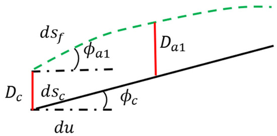
Figure 5.
Armor wire with imperfect geometrical relations.
Here, represents the circumferential distance between adjacent armor wires in the same layer under ideal conditions, represents the arc length parameter of the ideal armor wire, represents the circumferential distance between the armor wire with deviation and an adjacent ideal armor wire, represents the arc length parameter of the armor wire with deviation, represents the average helical angle of the deviated armor wire in segment , and represents the helical angle of the ideal armor wire.
After processing, the helical line with perfect geometric characteristics is considered a geodesic on a cylindrical surface. For a geodesic on a surface, the geodesic curvature . According to Equation (17), it can be seen that for a segment of an armor wire with geometric deviation defects, the average helical angle of that segment is influenced by the circumferential length difference and the axial length . From Equations (14)–(16), it is evident that this causes changes in the curvature components, especially changes in the geodesic curvature . The average geodesic curvature of segment , where the deviation defect is located, can be written as Equation (18).
3. Finite Element Model
In this study, commercial software SolidWorks 2020 and Abaqus 2023 were used for modeling and simulations, respectively, to simulate the nonlinear behavior of the lateral buckling of rectangular armor wires in flexible pipelines under wet conditions.
3.1. Geometric Model and Material Parameters
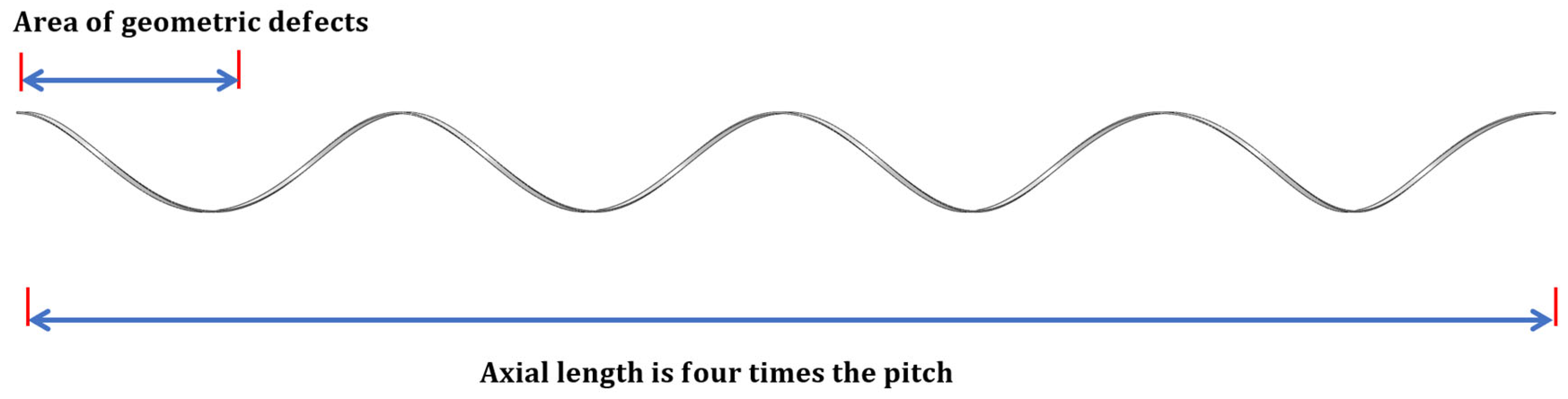
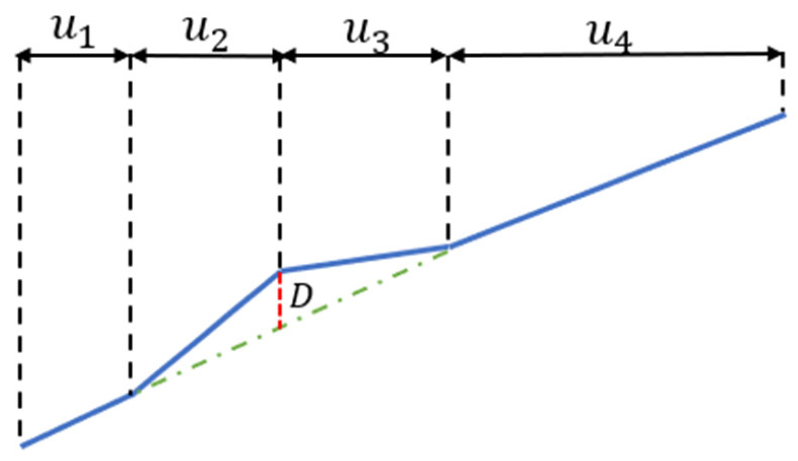
The overall geometry of the model is shown in Figure 6. First, multiple geometric models of four-pitch armor steel strips with different helical angles were created in SolidWorks. As shown in Figure 7, in each model, a segment with a certain axial length () was designated to represent a defect. This segment deviates from the perfect path (the green dashed line) by distance , simulating the deviation from the ideal position caused by manufacturing defects or pipeline bending. The average winding angle variation in this segment can be calculated using Equation (17), and then its average geodesic curvature can be obtained using Equation (18). The parameters of the defect segment for each helical angle are listed in Table 1.
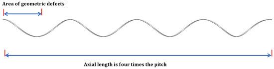
Figure 6.
Modeling of steel strip in SolidWorks.
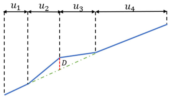
Figure 7.
Setting parameters for geometric defects in armored wire.

Table 1.
Defects of the A and B setups at different helix angles.
The lateral contact between adjacent armor wires in the same layer is ignored, so only a single armor wire is modeled. Material plasticity was taken into account during the simulation, and the corresponding parameters are listed in Table 2.
Table 2.
Material property parameters.
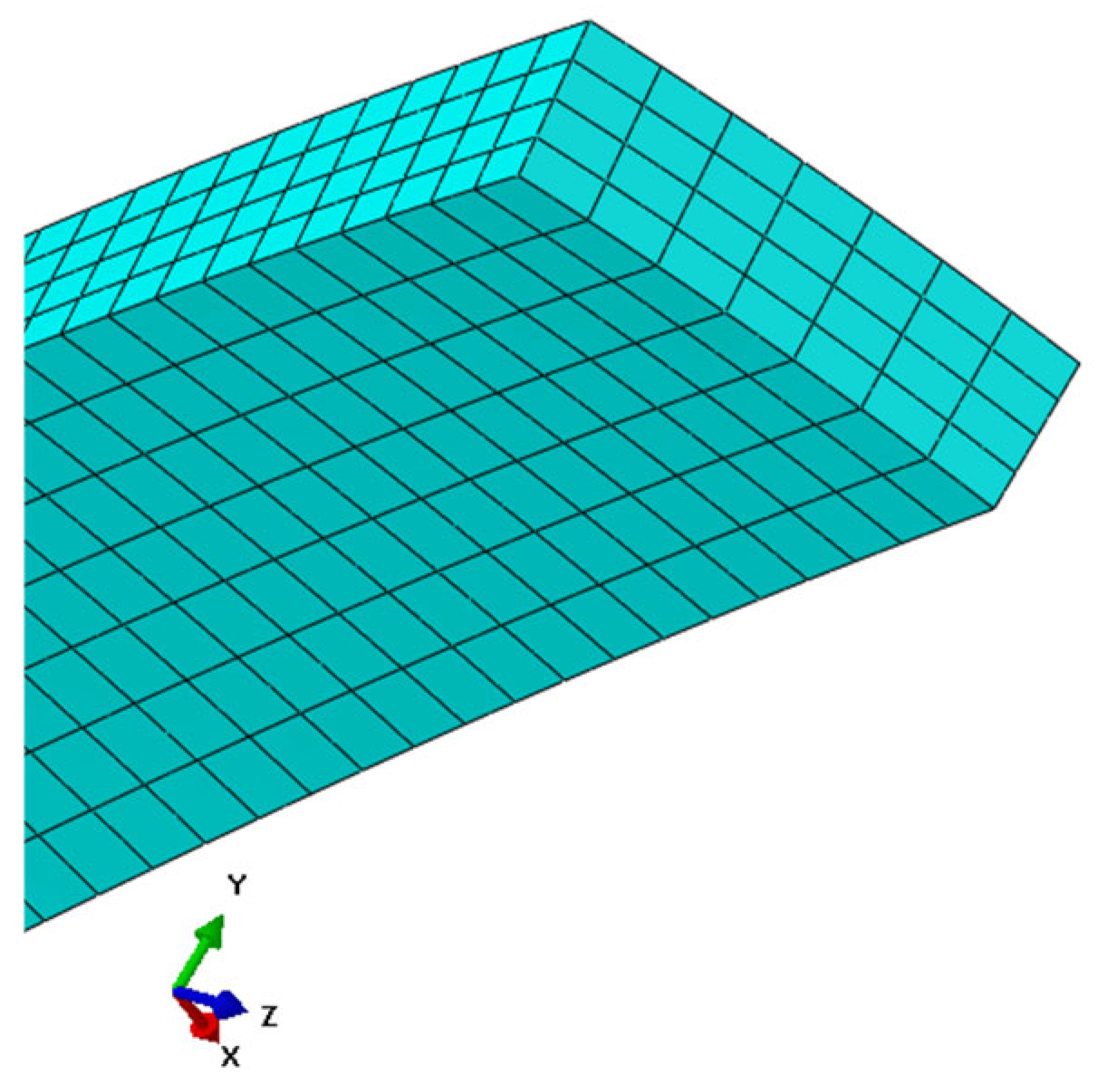
As shown in Figure 8, 7 and 4 C3D20 elements were used across the width and thickness of the rectangular steel strip, respectively.

Figure 8.
Meshing of steel strip cross-section.
3.2. Boundary Conditions and Displacement Load
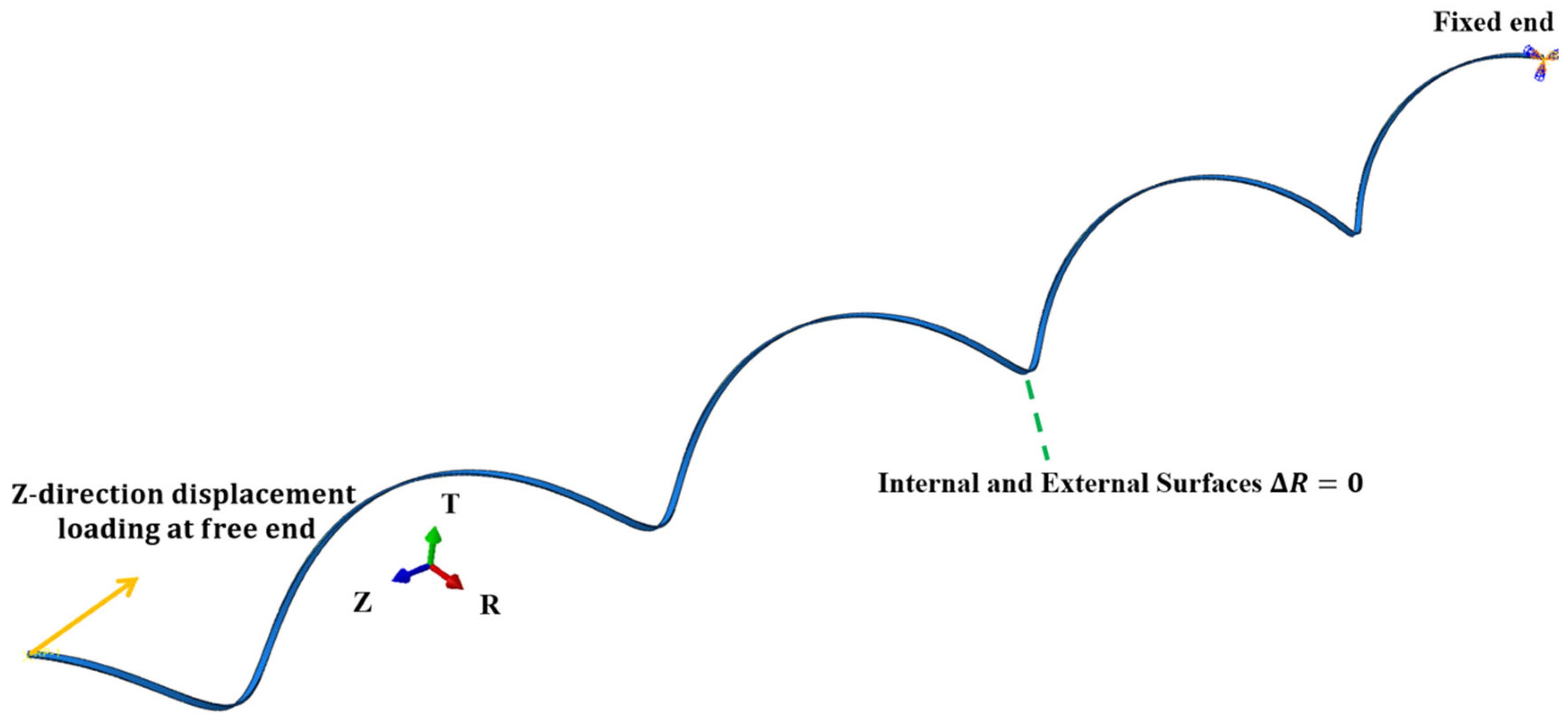
The finite element model is shown in Figure 9, where the entire model is initially in an undeformed state. To account for the wet conditions and ensure computational convergence, the radial displacement of the inner and outer surfaces of the steel strip is constrained in Abaqus to simulate the surface constraint effect of adjacent layers on the strip. The two end surfaces of the steel strip are defined as the free end and the fixed end, respectively. At the free end, the steel strip is subjected to an axial compressive displacement load, with no restriction on circumferential displacement. At the fixed end, the steel strip is fully constrained. To clearly observe the effect of deviation defects on the critical buckling load, all defects are positioned near the free end of the strip.
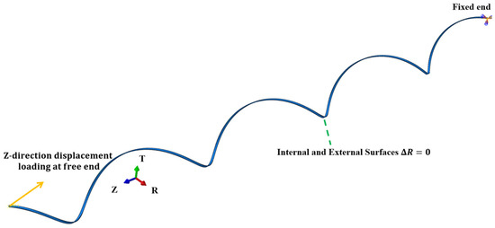
Figure 9.
Settings of boundary conditions for simulation model.
4. Results and Discussion
Several structural parameters influence the critical lateral buckling load of armor wires under wet conditions, including the cross-sectional dimensions of the steel strip, helix angle, and helix radius. This section primarily discusses the impact of defect severity on the lateral buckling resistance of the steel strip at different helix angles. To assess the effects of different helix angle designs for the same diameter pipeline, the same radius was used for all helix angles.
4.1. Load-Bearing Capacity Changes During Lateral Buckling of Steel Strip
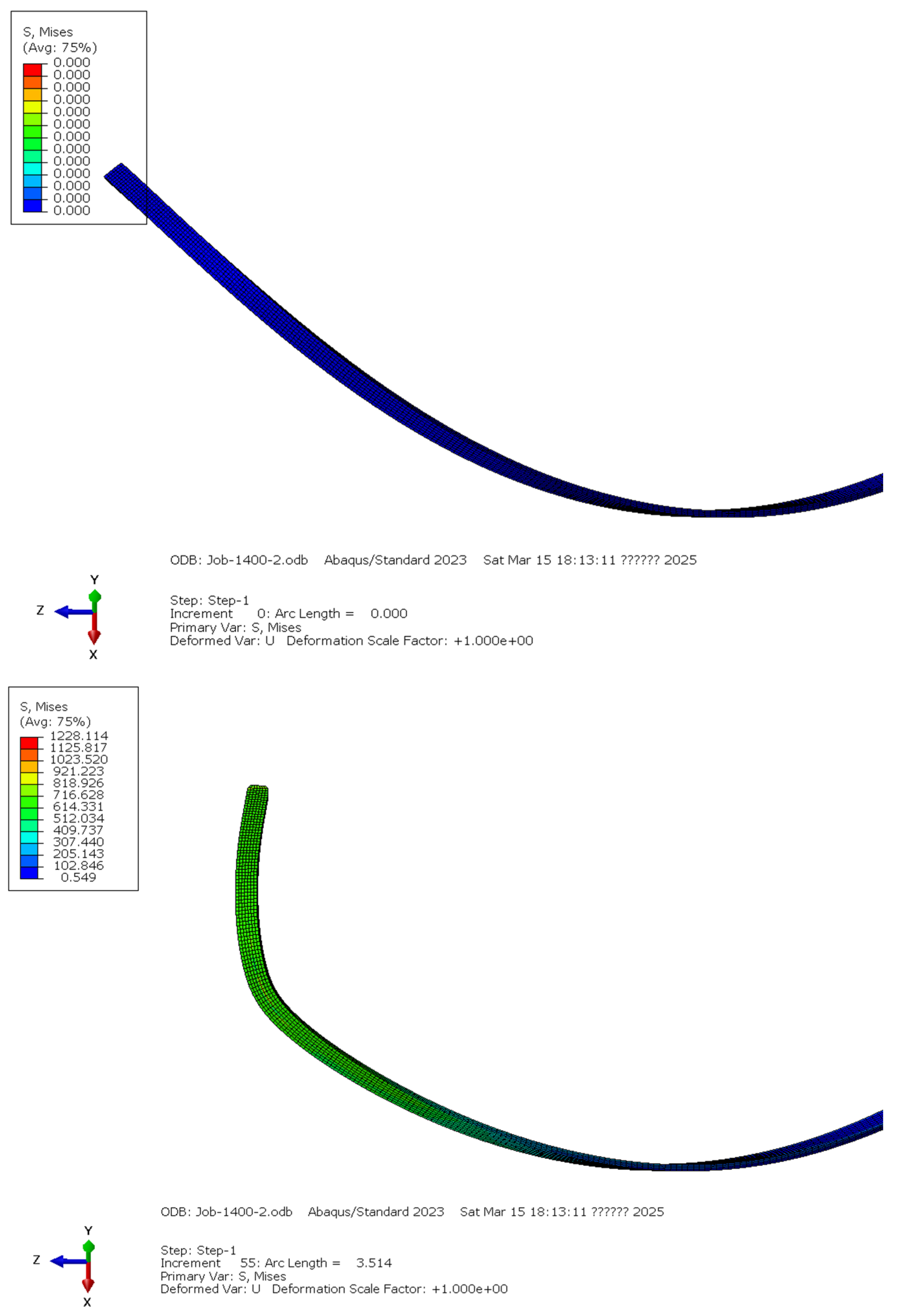
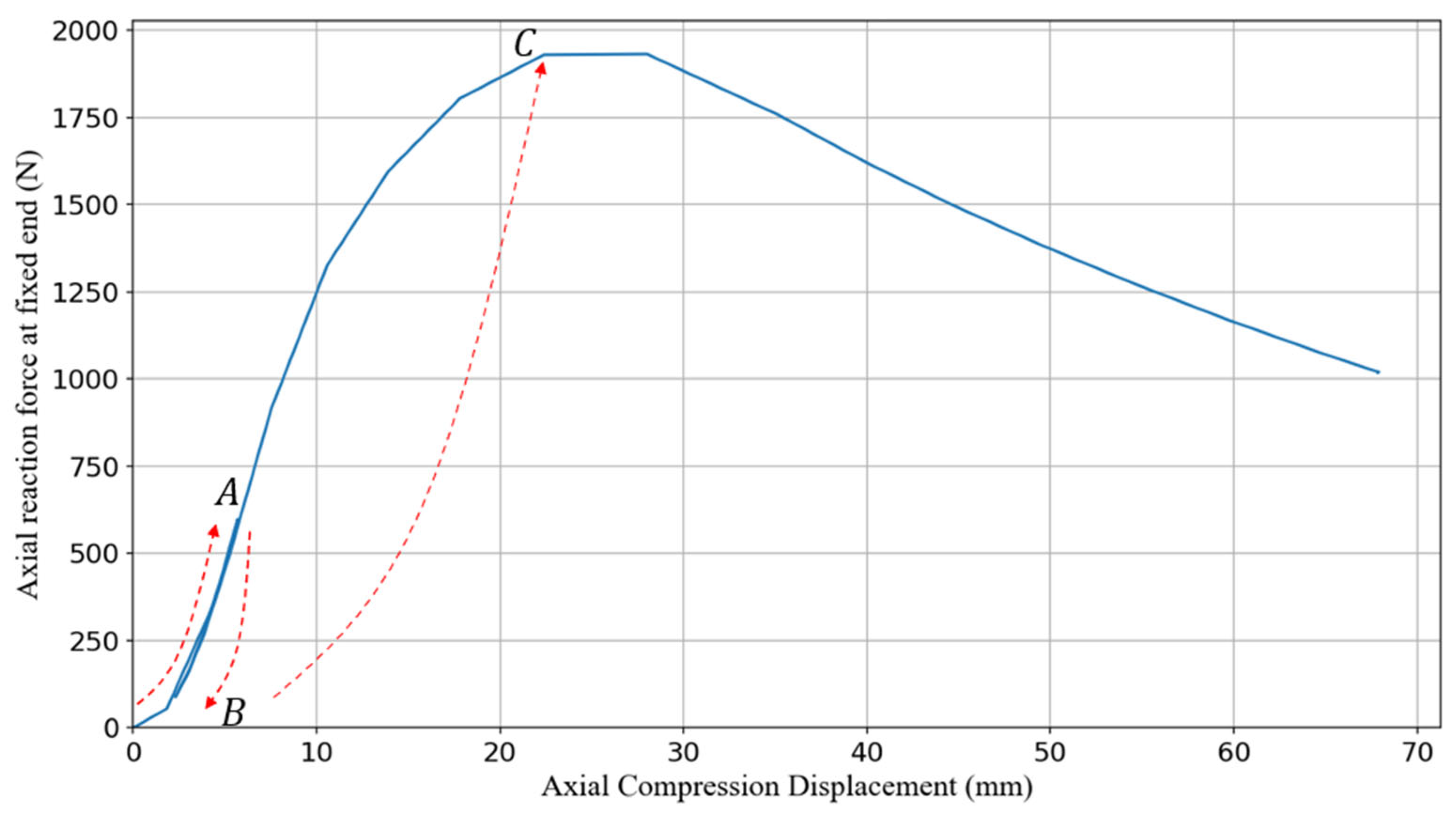
Taking the steel strip with a helix angle of 40° and a B-set defect as an example, the simulation process of lateral buckling is demonstrated. Figure 10 shows the lateral buckling shape of the armor steel strip before and after applying the displacement load. As illustrated in Figure 11, a displacement–compression curve is plotted. The results indicate that when the end displacement reaches 0.6% of the pitch length, the reaction force along the z-axis peaks at 597 N.
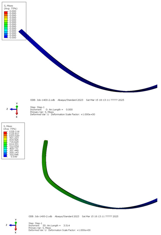
Figure 10.
Morphology before and after lateral buckling of armored wire.
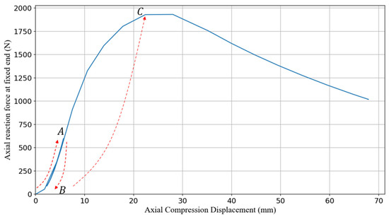
Figure 11.
Force–displacement curve of armored wire during lateral buckling.
By it comparing with the typical static instability response [21] and observing the deformation behavior of the armor wire, the loading process in Figure 11 can be divided into three stages.
- (1)
- In the initial stage, as the displacement load increases, the reaction force in the Z-axis direction starts from the origin O and grows almost linearly. Before reaching the critical load at point A, the steel strip remains in compression without any lateral buckling, and the structure stays stable.
- (2)
- Next, after the armor steel strip reaches the critical buckling load at point A, the structure enters a post-buckling state and becomes unstable. In the AB segment, the load and displacement values decrease as the simulation progresses, which is typical of an unstable static response. From the diagram, it can be observed that the distance between the OA and AB segments is short, with no significant hysteresis, primarily because the structure has not yet entered the plastic stage.
- (3)
- Finally, in the BC segment, the steel strip remains in the post-buckling stage, and the decrease in axial reaction force slows down. The free end of the armor wire enters the plastic stage, exhibiting noticeable lateral buckling deformation.
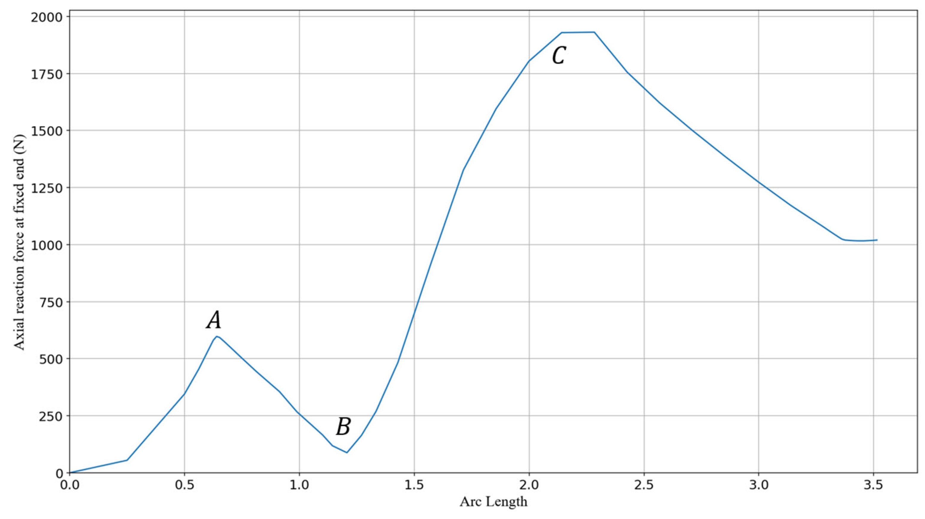
In engineering, the critical load that causes the helical structure to enter an unstable state, represented by point A, is often of the most concern. As shown in Figure 12, this point can be captured by the Riks method used in Abaqus, where the arc length represents the path length of a helically wound structure in the load–displacement space.
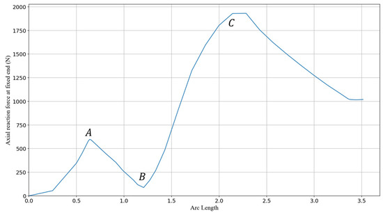
Figure 12.
Force–arc length parametric curves of armored wire during lateral buckling.
4.2. Mesh Convergence Analysis
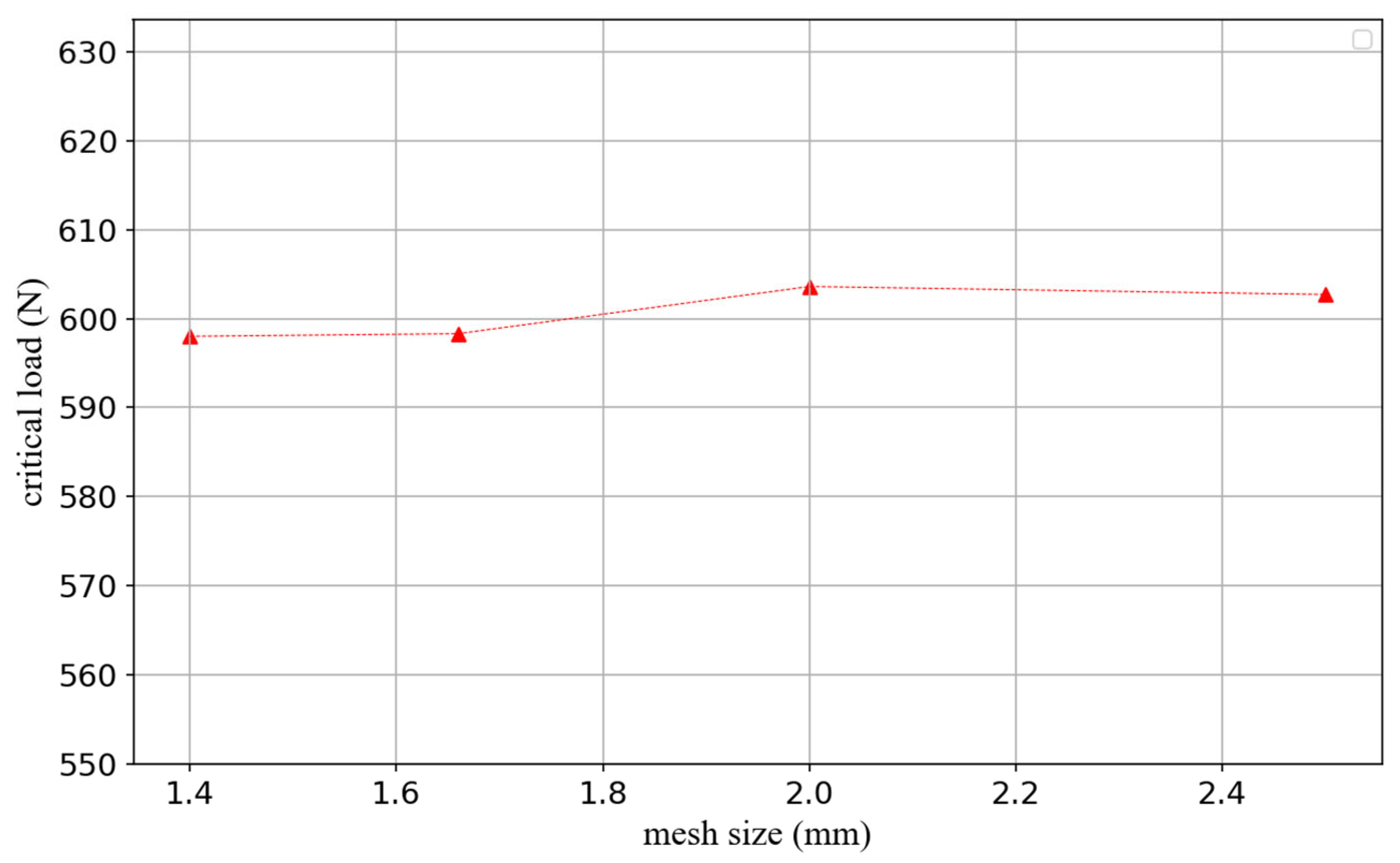
To ensure the accuracy of the simulation results, the mesh of the steel strip’s cross-section was refined, and a mesh convergence analysis was conducted. The following three refinement schemes were adopted: (1) 7 elements in the width direction (1.43 mm per element) and 4 elements in the thickness direction (0.75 mm per element); (2) 6 elements in the width direction (1.67 mm per element) and 3 elements in the thickness direction (1 mm per element); (3) 5 elements in the width direction (2 mm per element) and 3 elements in the thickness direction (1 mm per element); and (4) 4 elements in the width direction (2.5 mm per element) and 3 elements in the thickness direction (1 mm per element). Additionally, in each scheme, the mesh length in the tangential direction of the steel strip was set to 1.5 mm. The calculated critical lateral buckling load for the steel strip with a helix angle of 40° and a B-set defect is shown in Figure 13. Under these mesh refinement schemes, the results have converged.
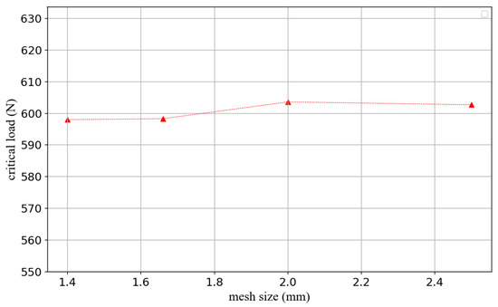
Figure 13.
Mesh convergence verification.
4.3. Model Validation
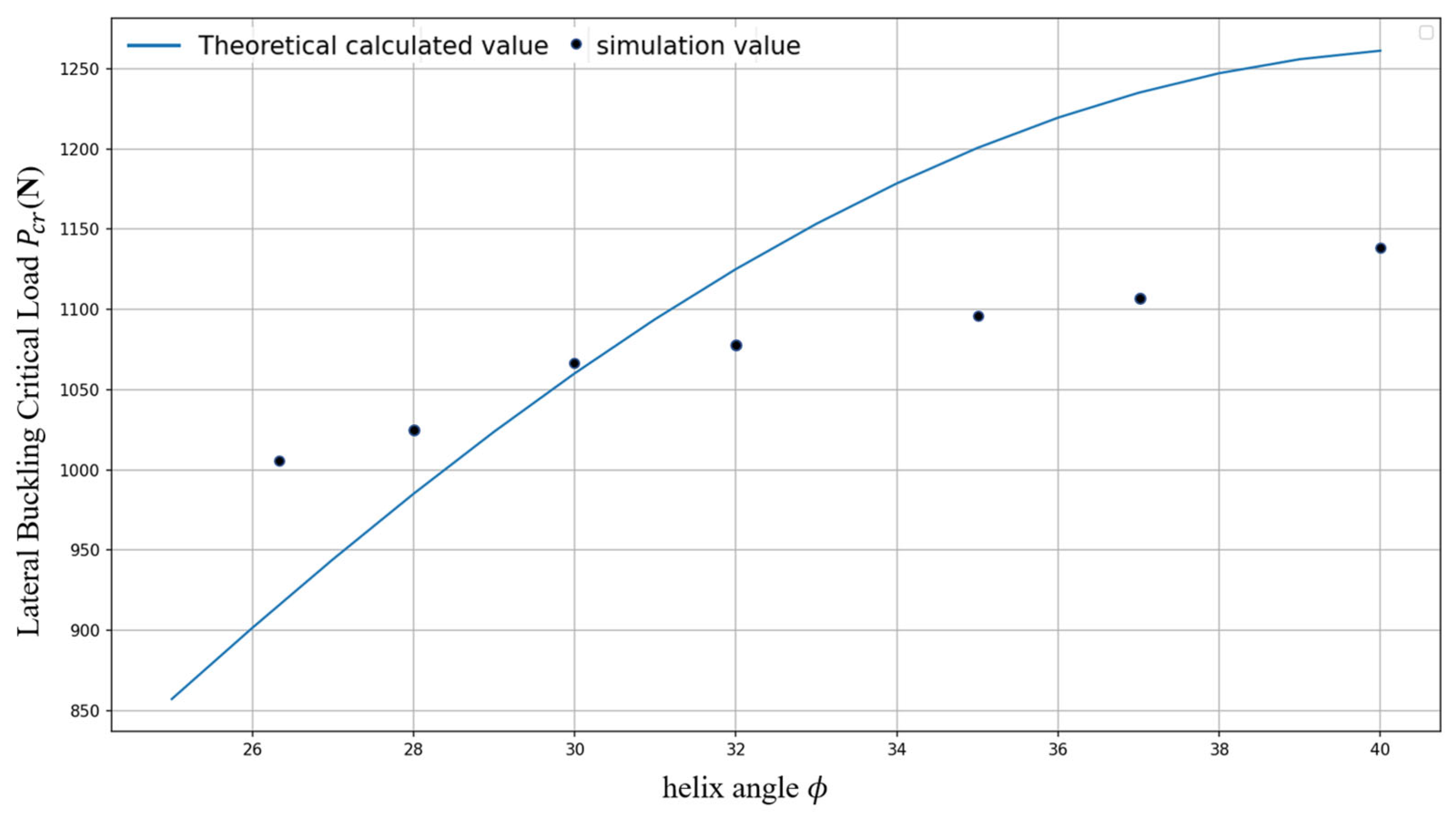
To validate the accuracy of the simulation model, the critical loads of steel strips without set defects at different helix angles were compared with the results obtained from theoretical calculations. According to the theory proposed by Sævik and Thorsen [5], the minimum critical load for lateral buckling of the steel strip is given by the following:
where is the helix angle of the armor wires, n is the number of armor wires, is considered the radius of the pipe, and are the bending stiffness about the weak axis and strong axis of the armor wire, and is the torsional stiffness. In the comparison process, is set to 0.1 m, with the steel strip cross-section width set at 10 mm and thickness at 3 mm.
As shown in Figure 14, the theoretical critical load values gradually increase across the four different helix angles, indicating that for flexible pipelines of the same diameter, a higher helix angle enhances the lateral buckling resistance of the tensile armor layer. The errors between the critical load values obtained from the simulation model and the theoretical results are +7.6%, +2%, −8.1%, and −10.7%, respectively, demonstrating a good correlation between the theoretical and simulation results.
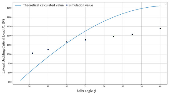
Figure 14.
Comparison of simulated and theoretical values of lateral buckling critical loads.
4.4. Internal Force Changes in Armor Wire Cross-Section During Lateral Buckling
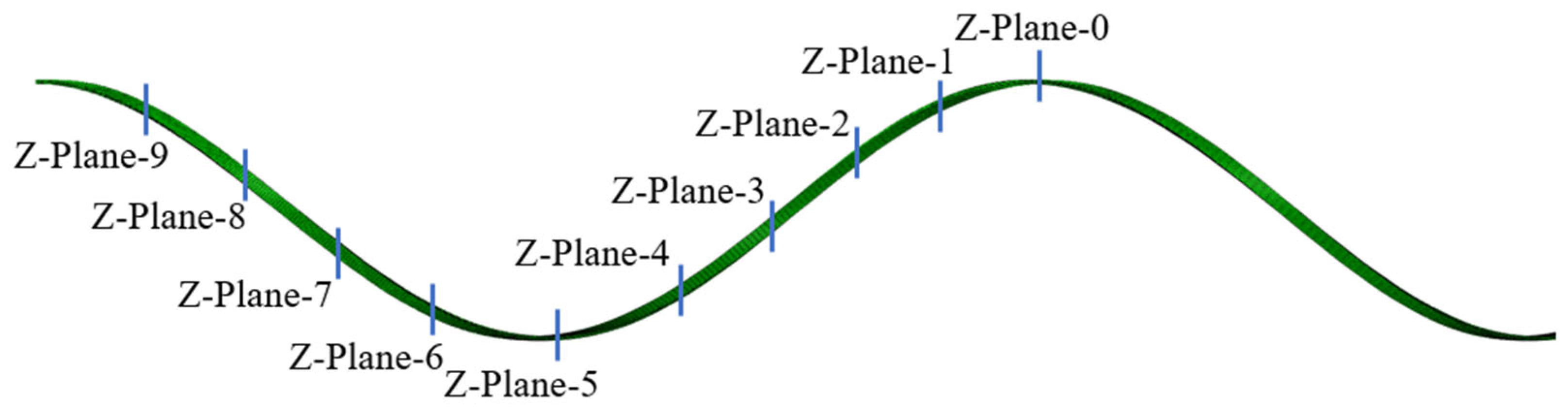
As shown in Figure 15, to understand the internal force changes in the cross-section of the steel strip with deviation defects when subjected to the critical lateral buckling load, one pitch of the helical structure containing the defect was selected, with 10 equally spaced cross-sections analyzed. The forces and bending moments at each cross-section were examined.
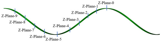
Figure 15.
The distribution setup of the armored steel strip with the deviation defect along the Z-axis cross-section.
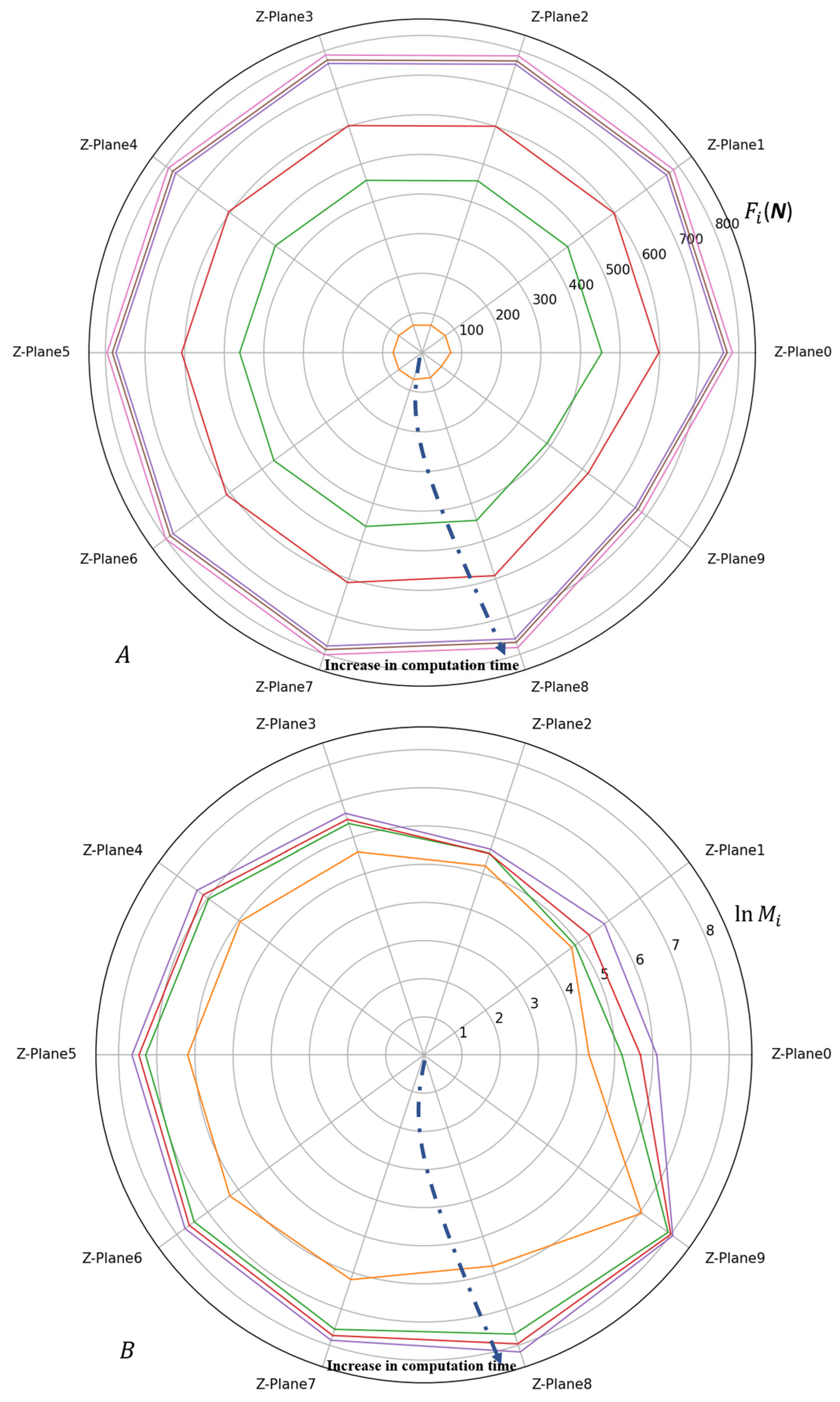
In Figure 16, the internal force values of each section at the same moment are sequentially connected, and the order of different moments is indicated by dashed arrows. In Figure 16A, it can be observed that the forces on each cross-section increase uniformly with the displacement load, with minimal differences between the sections. In Figure 16B, to better observe the variation in the values, the sectional bending moment is presented in logarithmic scale. It can be seen that the increase in bending moment for sections 7, 8, and 9, where the deviation defects are located, is higher compared to the other sections. Comparing Figure 16A,B, it is evident that, unlike the axial forces, the bending moments in Z-Plane 8 increase the fastest, and the ratio between the maximum and minimum values across the 10 sections is much higher for the bending moments than for the axial forces. This indicates that the influence of the deviation defect on the lateral buckling resistance of the armor wire is primarily exerted through changes in the cross-sectional bending moments.
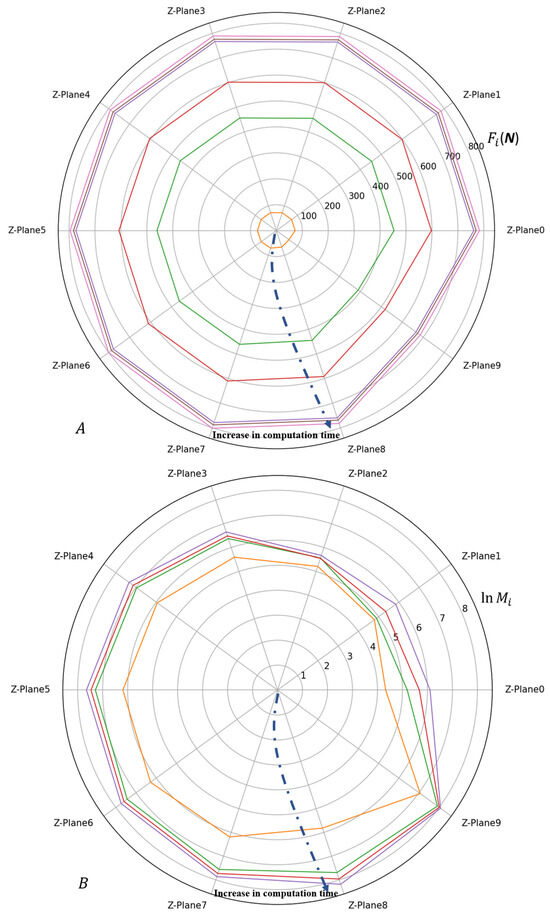
Figure 16.
The variation in interface internal forces during the simulation process. (A) Section Reaction Force (B) Section Bending Moment.
4.5. Circumferential Displacement Changes in Armor Wire During Lateral Buckling
The displacement changes in the XoZ plane are shown in Figure 17, where it can be observed that the sections of the steel strip near the circumferential free end experience larger displacements, while the sections closer to the fixed end have smaller displacements. The locations with significant in-plane bending are within the range of the deviation defect segment, and the bending direction aligns with the direction of the in-plane deviation defect.
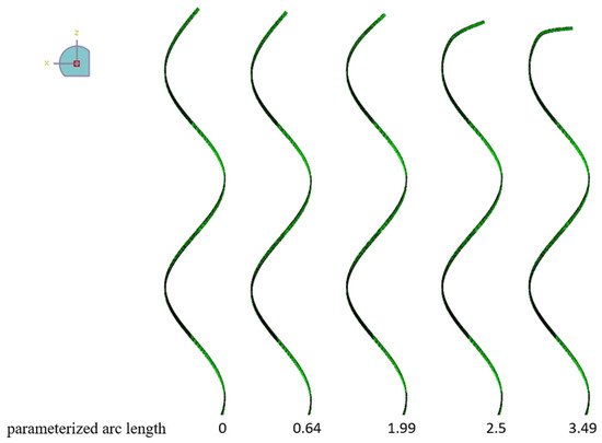
Figure 17.
Lateral buckling pattern of armored wire in XoZ plane.
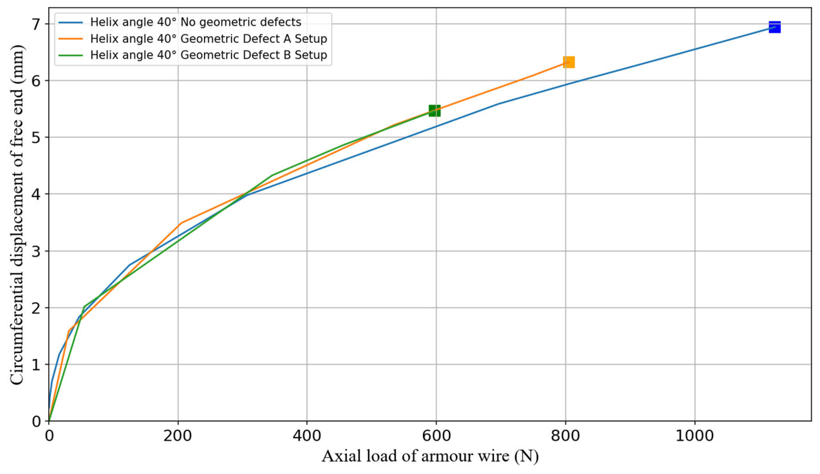
The circumferential displacement of the free end of the steel strip with a 40° helix angle is shown in Figure 18. It can be seen that for all three deviation settings, as the axial load increases towards the critical load, the circumferential displacement follows a similar upward trend. The greater the deviation, the smaller the maximum circumferential displacement at the point of lateral instability, and the earlier this maximum is reached. This phenomenon may be attributed to the fact that the internal forces in the cross-sections of the steel strip with deviation defects increase more rapidly, resulting in a reduced allowable circumferential displacement at the free end as the degree of deviation increases.
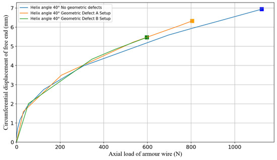
Figure 18.
Circumferential displacement of free end of armored wire for three defect settings.
4.6. Influence of Defect Location on Critical Lateral Buckling Load
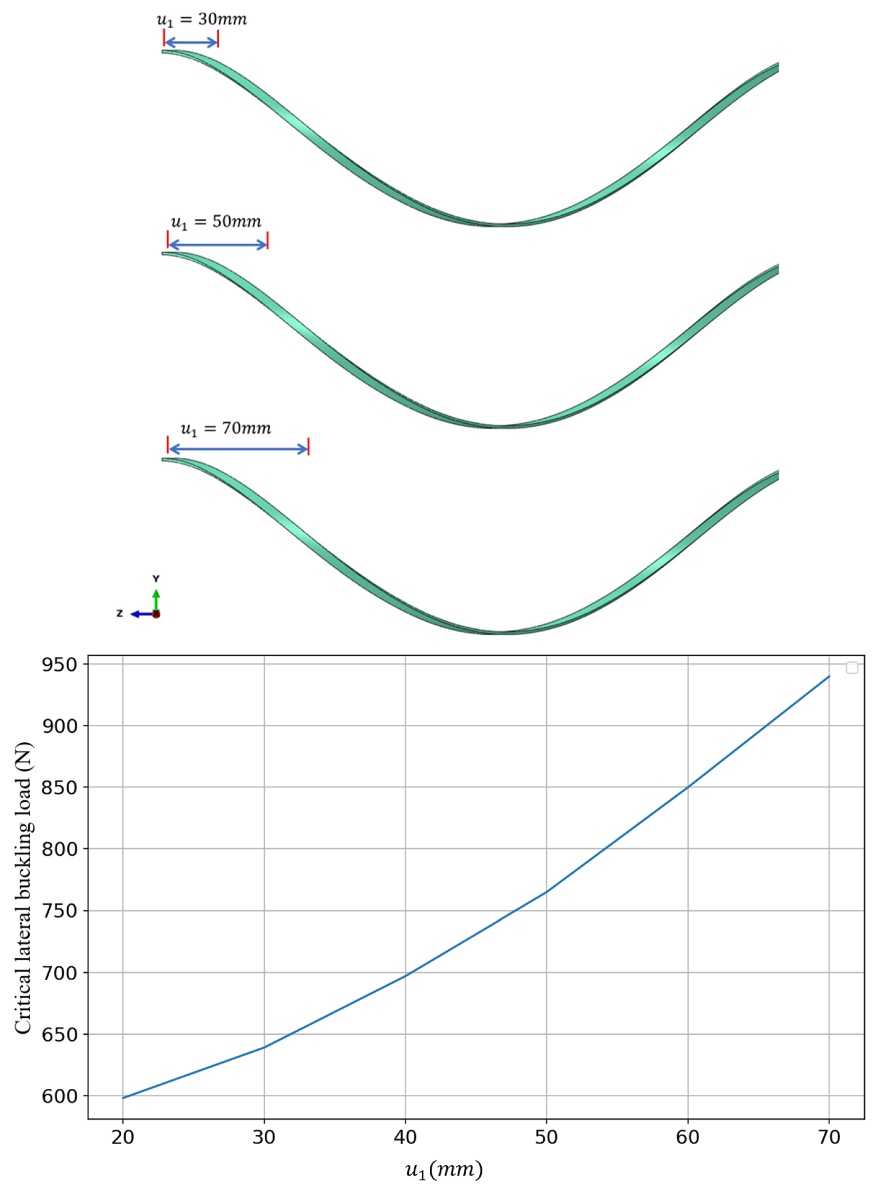
This section discusses the impact of the starting position of the geometric deviation defect on the lateral buckling stability of the armor wire. Six starting positions were set at = 20 mm, 30 mm, 40 mm, 50 mm, 60 mm, 70 mm. The parameters , , , of the geometric deviation defect are the same as those in the B-set configuration.
The variation in the critical lateral buckling load with respect to is shown in Figure 19. When the geometric deviation defect is positioned near the free end of the steel strip at = 20 mm, the critical buckling load is the lowest. As the defect moves closer to the fixed end of the steel strip, the critical buckling load gradually increases. Comparing the settings = 20 mm and = 70 mm, the critical lateral buckling load differs by 28%. This phenomenon may be attributed to the effective length change in the steel strip under the boundary conditions of one fixed end and one circumferentially free end. When the defect is closer to the free end, the effective length of the armor wire increases, resulting in a lower critical lateral buckling load. Therefore, the location of the geometric deviation defect significantly influences the critical lateral buckling load of the armor wire.
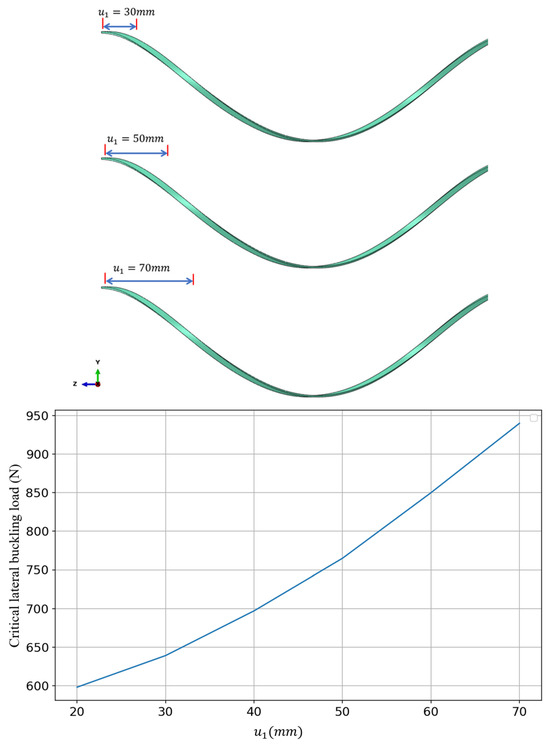
Figure 19.
Effect of armored wire deviation defect parameter on lateral buckling critical load.
4.7. Influence of Deviation Severity on Critical Buckling Load
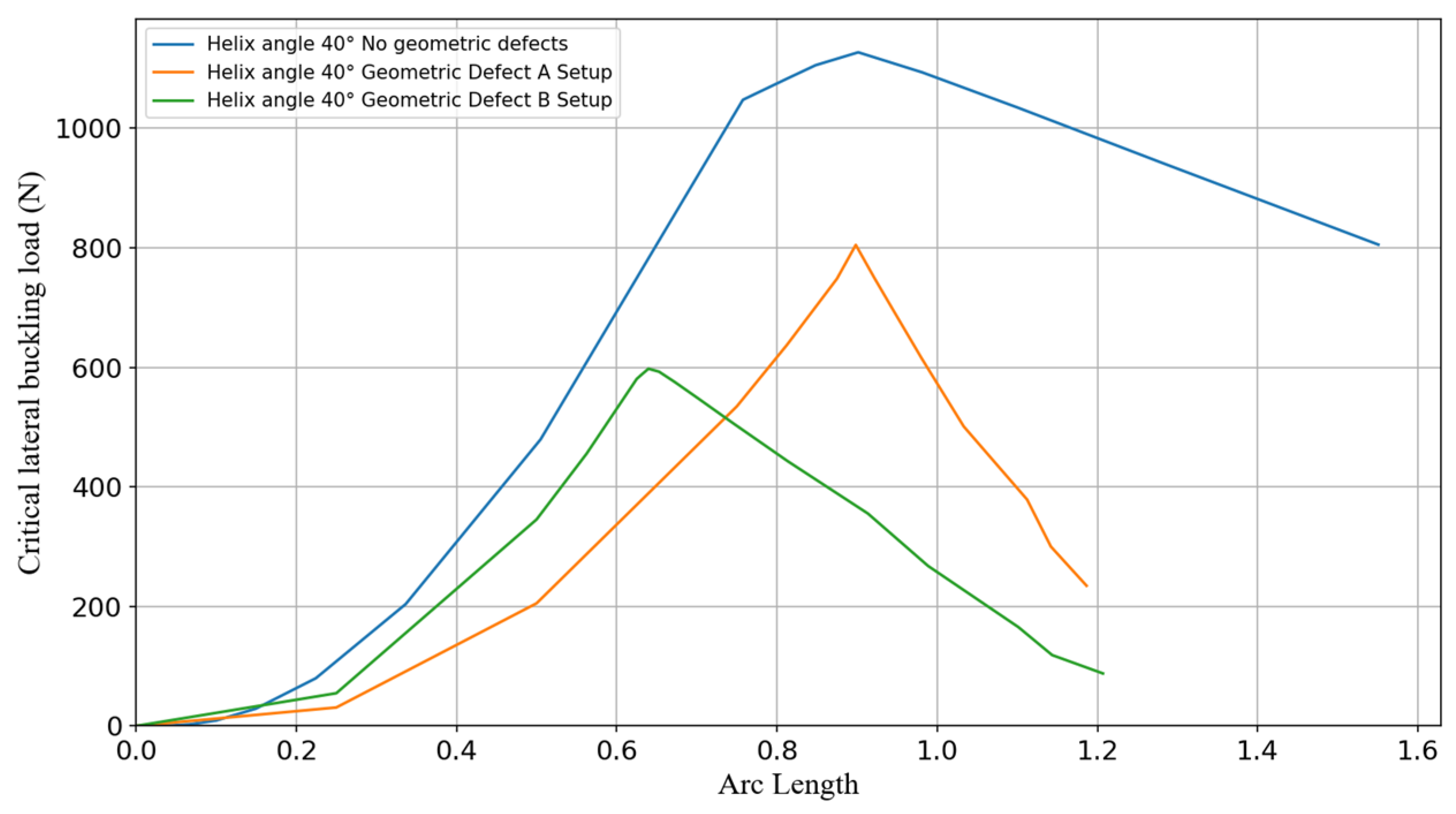
The load–arc length curves at the point of lateral instability are extracted continuously, as shown in Figure 20. It is evident that the increase in the severity of the set defects has a significant impact on the reduction in the critical buckling load. This indicates that the uneven distribution of the armor steel strips caused by manufacturing defects and repeated bending is a key factor leading to lateral instability. Specifically, the geodesic curvature set within the surface for the armor wire essentially configures the degree and direction of bending for the steel strip, making lateral buckling more likely to occur.
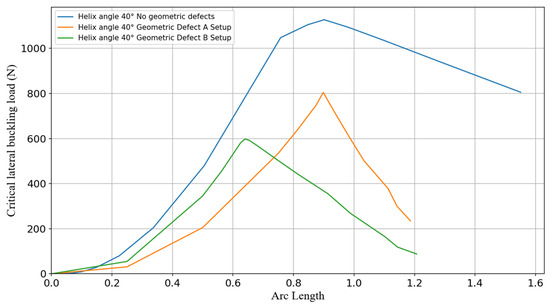
Figure 20.
Lateral buckling critical load of armored wires with helix angle of 40° as affected by deviation defects.
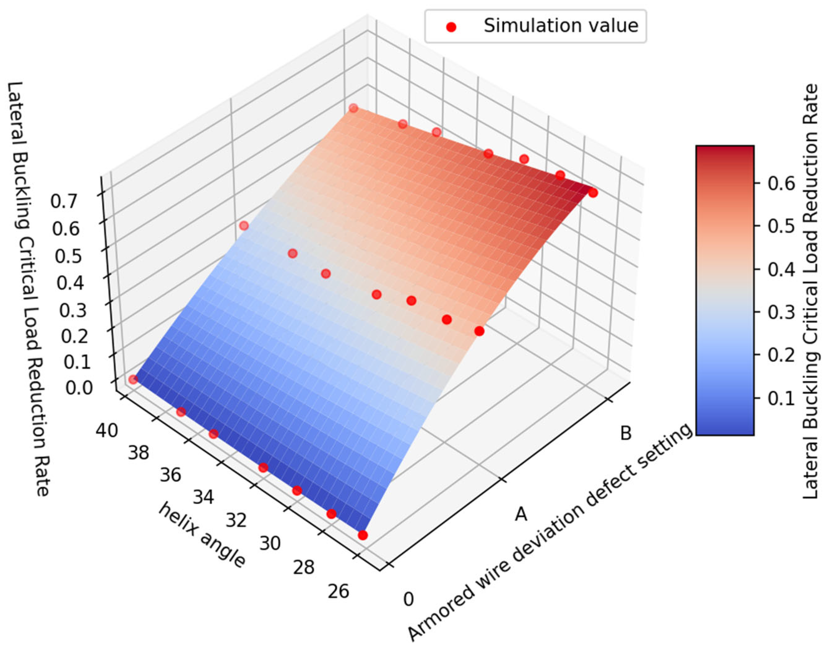
The critical lateral buckling load of steel strips with perfect geometric shapes at each helix angle is taken as the reference. The effect of two levels of deviation severity on the critical load values is then investigated. The reduction factor is defined as follows:
where is the critical buckling load of the steel strip with a deviation, and is the critical buckling load of the steel strip with a perfect geometric shape.
The values of at different helix angles are plotted in Figure 21. It can be observed that as the degree of deviation increases, the critical buckling load decreases for all helix angles, and the reduction rate is higher for smaller helix angles. This indicates that as the helix angle increases within the range of 26.2° to 40°, the lateral buckling stability of the helical structure improves progressively.

Figure 21.
Critical load reduction for lateral buckling of armored wires due to various defect settings at different helix angles.
5. Conclusions
This paper proposes a method to quantify manufacturing deviation defects by calculating the circumferential distance variation in the armored wire and utilizes SolidWorks and Abaqus for the geometric modeling and simulation of the steel strips. The compression response of the steel strips with manufacturing deviations under wet conditions is obtained. The simulation results show that, compared to defect-free armored steel strips, the discrepancy between the critical buckling load and the theoretical value ranges from 2% to 10%, depending on the helical angle, thus proving the validity of the model. During the lateral buckling process of the armored steel strips, deviation defects under different helical angles have a significant impact on the critical lateral buckling load. The analysis indicates that the increase in the cross-sectional bending moment caused by deviation defects is the main factor leading to the reduction in the critical lateral buckling load. To improve the lateral buckling resistance of the pipeline armor layer and reduce sensitivity to manufacturing errors, the helical angle of the steel strips can be appropriately increased. The proposed method for quantifying manufacturing deviation defects and the analysis of how deviation defects affect the lateral stability of helically wound steel strips can provide a reference for evaluating the manufacturing quality of tensile armor steel strips.
Additionally, future research may explore new simulation methods that account for the friction between the steel strip and adjacent layers. It would also be beneficial to develop circumferential deviation models for tensile armor wires based on bending cycles and bending curvatures, allowing the previously complex multi-bending simulations to be simplified into the straight-pipe analysis models discussed in this paper, thereby improving simulation efficiency.
Author Contributions
All authors contributed to the study conception and design. Material preparation, data collection, and analysis were performed by Y.L. (Yongyu Li), Q.L. and H.L. The first draft of the manuscript was written by Y.L. (Yongyu Li) and all authors commented on previous versions of the manuscript. All authors have read and agreed to the published version of the manuscript.
Funding
This research was financially supported by the National Natural Science Foundation of China (52201312), the National Key R&D Program of China (2021YFA1003501), the Dalian city supports innovation and entrepreneurship projects for high-level talents (2021RD16), and the Natural Science Foundation of Liaoning Province of China (2023-BSBA-052). These supports are gratefully acknowledged.
Institutional Review Board Statement
Not applicable.
Informed Consent Statement
Not applicable.
Data Availability Statement
The data presented in this study are available on request from the corresponding author.
Conflicts of Interest
The authors declare no conflict of interest.
References
- Secher, P.; Bectarte, F.; Felix-Henry, A. Lateral Buckling of Armor Wires in Flexible Pipes: Reaching 3000m Water Depth. In Proceedings of the ASME 2011 30th International Conference on Ocean, Offshore and Arctic Engineering, Rotterdam, The Netherlands, 19–24 June 2011; Volume 4: Pipeline and Riser Technology. pp. 421–428. [Google Scholar] [CrossRef]
- Østergaard, N.H.; Lyckegaard, A.; Andreasen, J.H. On Lateral Buckling Failure of Armour Wires in Flexible Pipes. In Proceedings of the ASME 2011 30th International Conference on Ocean, Offshore and Arctic Engineering, Rotterdam, The Netherlands, 19–24 June 2011; Volume 4: Pipeline and Riser Technology. pp. 289–298. [Google Scholar] [CrossRef]
- Østergaard, N.; Lyckegaard, A.; Andreasen, J.H. Imperfection Analysis of Flexible Pipe Armor Wires in Compression and Bending. Appl. Ocean. Res. 2012, 38, 40–47. [Google Scholar] [CrossRef]
- Li, X.; Vaz, M.A.; Custódio, A.B. Analytical Model for Tensile Armors Lateral Deflections and Buckling in Flexible Pipes. Mar. Struct. 2019, 64, 211–228. [Google Scholar] [CrossRef]
- Sævik, S.; Thorsen, M.J. An Analytical Treatment of Buckling and Instability of Tensile Armors in Flexible Pipes. J. Offshore Mech. Arct. Eng. 2017, 139, 041701. [Google Scholar] [CrossRef]
- Tan, Z.; Loper, C.; Sheldrake, T.; Karabelas, G. Behavior of Tensile Wires in Unbonded Flexible Pipe Under Compression and Design Optimization for Prevention. In Proceedings of the 25th International Conference on Offshore Mechanics and Arctic Engineering, Hamburg, Germany, 4–9 June 2006; Volume 4: Terry Jones Pipeline Technology; Ocean Space Utilization; CFD and VIV Symposium. pp. 43–50. [Google Scholar] [CrossRef]
- Sævik, S.; Ji, G. Differential Equation for Evaluating Transverse Buckling Behavior of Tensile Armour Wires. In Proceedings of the ASME 2014 33rd International Conference on Ocean, Offshore and Arctic Engineering, San Francisco, CA, USA, 8–13 June 2014; Volume 6B: Pipeline and Riser Technology. p. V06BT04A021. [Google Scholar] [CrossRef]
- Sævik, S.; Thorsen, M.J. Techniques for Predicting Tensile Armour Buckling and Fatigue in Deep Water Flexible Pipes. In Proceedings of the ASME 2012 31st International Conference on Ocean, Offshore and Arctic Engineering, Rio de Janeiro, Brazil, 1–6 July 2012; Volume 3: Pipeline and Riser Technology. pp. 469–482. [Google Scholar] [CrossRef]
- Caleyron, F.; Guiton, M.; Leroy, J.-M.; Perdrizet, T.; Charliac, D.; Estrier, P.; Paumier, L. A Multi-Purpose Finite Element Model for Flexible Risers Studies. In Proceedings of the ASME 2014 33rd International Conference on Ocean, Offshore and Arctic Engineering, San Francisco, CA, USA, 8–13 June 2014; Volume 6A: Pipeline and Riser Technology. p. V06AT04A015. [Google Scholar] [CrossRef]
- Ye, N.; Ji, G.; Sævik, S. Lateral Buckling of Tensile Armor Wires in Flexible Pipe Subject to Axial Compressive and Cyclic Bending Load. In Proceedings of the ASME 2023 42nd International Conference on Ocean, Offshore and Arctic Engineering, Melbourne, Australia, 11–16 June 2023; Volume 3: Materials Technology; Pipelines, Risers, and Subsea Systems. p. V003T04A013. [Google Scholar] [CrossRef]
- Lu, Q.; Yang, Z.; Yang, Y.; Yan, J.; Yue, Q. Study on the Mechanism of Bird-Cage Buckling of Armor Wires Based on Experiment. In Proceedings of the ASME 2017 36th International Conference on Ocean, Offshore and Arctic Engineering, Trondheim, Norway, 25–30 June 2017; Volume 5A: Pipelines, Risers, and Subsea Systems. p. V05AT04A018. [Google Scholar] [CrossRef]
- Favaro Borges, M.; Talgatti, O.L.; Mosquen, A. Radial Instability of Flexible Pipes with Defects in the High Resistance Bandage and External Sheath. In Proceedings of the ASME 2017 36th International Conference on Ocean, Offshore and Arctic Engineering, Trondheim, Norway, 25–30 June 2017; Volume 5A: Pipelines, Risers, and Subsea Systems. p. V05AT04A025. [Google Scholar] [CrossRef]
- Li, X.; Vaz, M.A.; Custódio, A.B. Analytical and Experimental Studies on Flexible Pipes Tensile Armors Lateral Instability in Cyclic Bending. Mar. Struct. 2019, 67, 102630. [Google Scholar] [CrossRef]
- Caleyron, F.; Leroy, J.-M.; Guiton, M.; Duchêne, P.; Estrier, P.; Vraniskoski, K.; Damiens, A. Stresses in Tensile Armour Layers of Unbounded Flexible Risers Loaded with External Pressure: Application to Lateral Buckling Mode. In Proceedings of the ASME 2017 36th International Conference on Ocean, Offshore and Arctic Engineering, Trondheim, Norway, 25–30 June 2017; Volume 5A: Pipelines, Risers, and Subsea Systems. p. V05AT04A006. [Google Scholar] [CrossRef]
- Yang, Z.; Yan, J.; Zhang, L.; Shi, D.; Lu, Q. Research on Lateral Buckling Mechanism of Tensile Armor Wires in Unbonded Flexible Pipe. In Proceedings of the ASME 2020 39th International Conference on Ocean, Offshore and Arctic Engineering, Virtual, Online, 3–7 August 2020. Volume 4: Pipelines, Risers, and Subsea Systems. [Google Scholar] [CrossRef]
- Vaz, M.A.; Rizzo, N.A.S. A Finite Element Model for Flexible Pipe Armor Wire Instability. Mar. Struct. 2011, 24, 275–291. [Google Scholar] [CrossRef]
- De Paiva, L.F.; Vaz, M.A. An Empirical Model for Flexible Pipe Armor Wire Lateral Buckling Failure Load. Appl. Ocean Res. 2017, 66, 46–54. [Google Scholar] [CrossRef]
- Østergaard, N.H.; Lyckegaard, A.; Andreasen, J.H. A Method for Prediction of the Equilibrium State of a Long and Slender Wire on a Frictionless Toroid Applied for Analysis of Flexible Pipe Structures. Eng. Struct. 2012, 34, 391–399. [Google Scholar] [CrossRef]
- Zhou, C.; Sævik, S.; Ye, N.; Ji, G. Effect of Lay Angle of Anti-Buckling Tape on Lateral Buckling Behavior of Tensile Armors. In Proceedings of the ASME 2015 34th International Conference on Ocean, Offshore and Arctic Engineering, St. John’s, NF, Canada, 31 May–5 June 2015; Volume 5A: Pipeline and Riser Technology. p. V05AT04A040. [Google Scholar] [CrossRef]
- Li, Y.; Wu, S.; Liu, C.; Lu, Q.; Chen, J.; Yan, J.; Yue, Q. Modelling and Control of Tension in a Flexible Pipe Tensile Armour Manufacturing Process. Int. J. Adv. Manuf. Technol. 2024, 133, 3927–3936. [Google Scholar] [CrossRef]
- Dassault Systèmes, Abaqus/CAE User’s Guide, Dassault Systèmes. 2024. Available online: https://help.3ds.com (accessed on 7 January 2024).


Disclaimer/Publisher’s Note: The statements, opinions and data contained in all publications are solely those of the individual author(s) and contributor(s) and not of MDPI and/or the editor(s). MDPI and/or the editor(s) disclaim responsibility for any injury to people or property resulting from any ideas, methods, instructions or products referred to in the content. |
© 2025 by the authors. Licensee MDPI, Basel, Switzerland. This article is an open access article distributed under the terms and conditions of the Creative Commons Attribution (CC BY) license (https://creativecommons.org/licenses/by/4.0/).