
Finite Element Modelling of Pressure Armour Unlocking Failure in Unbonded Flexible Risers


Abstract
1. Introduction
2. Finite Element Modelling
- The structure is assumed to be stress-free in the initial state, and any prestress introduced by fabrication is ignored.
- Geometrical imperfections are not considered. It is assumed that the pressure armour is laid in a perfect helical configuration.
- The inner sheath is modelled as a tubular shell with uniform thickness and its extrusion into the gaps of pressure armour is not considered in the initial unloaded condition.
- It is assumed that the carcass will not be self-contacted and maintain its integrity during the whole simulation. For the sake of simplification, the radial support from the carcass layer is replicated by a frictionless rigid tubular surface.
- Considering that pressure armour layer unlocking may be a secondary effect of a birdcage failure, outer layers are removed to reproduce the birdcage failure and diminish the radially outward displacement constraint these outer layers place on the pressure armour layer.
2.1. Geometry and Material
2.1.1. Pressure Armour Layer
2.1.2. Inner Sheath
2.1.3. Carcass
2.2. Overbending Model
2.2.1. Contact
2.2.2. Mesh Topology
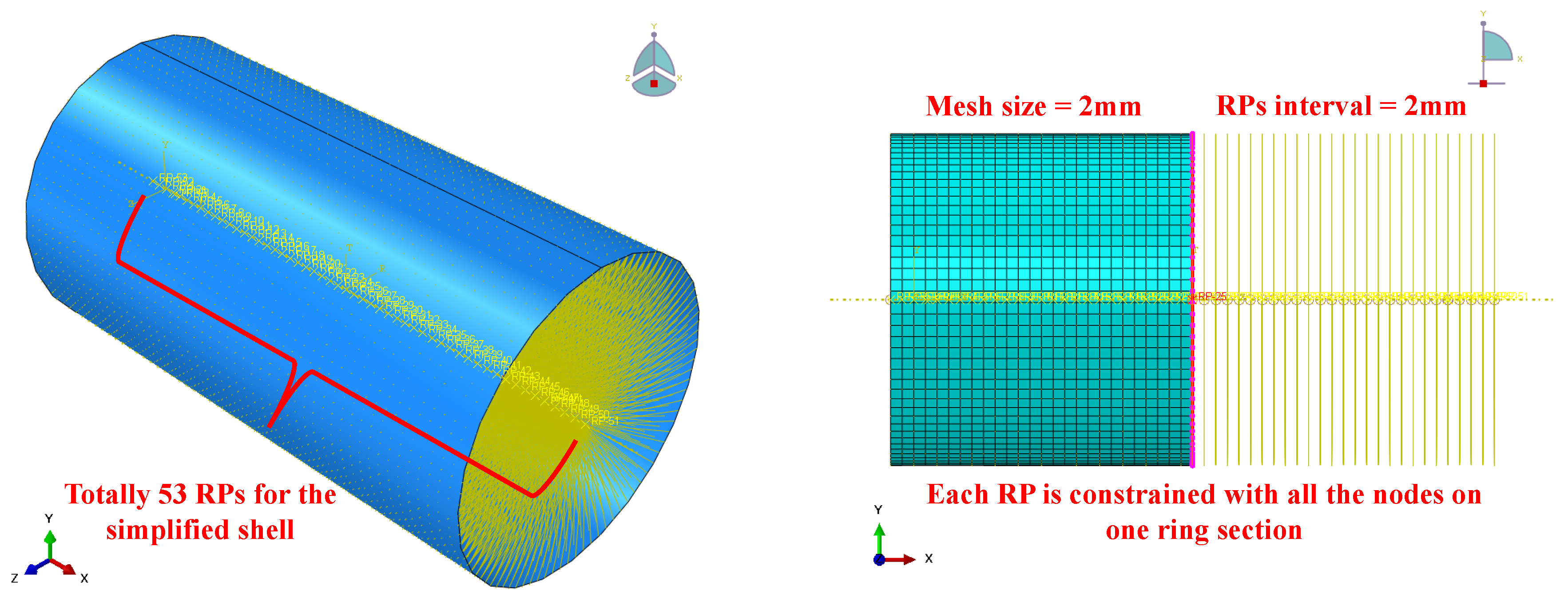
- Simplified surface: For the sake of cross-section properties, the mesh of the simplified shell is generated by SFM3D4R element type, which is a 3D linear four-node quadrilateral surface element with reduced integration. The global seed size is fixed at 2 mm while the total length of the simplified shell in a 14.5-pitch model equals 104 mm. The linear eight-node hexahedral brick element with enhanced hourglass and distortion control is selected for both the polymer layer of the structured mesh and the pressure armour layer of the swept mesh.
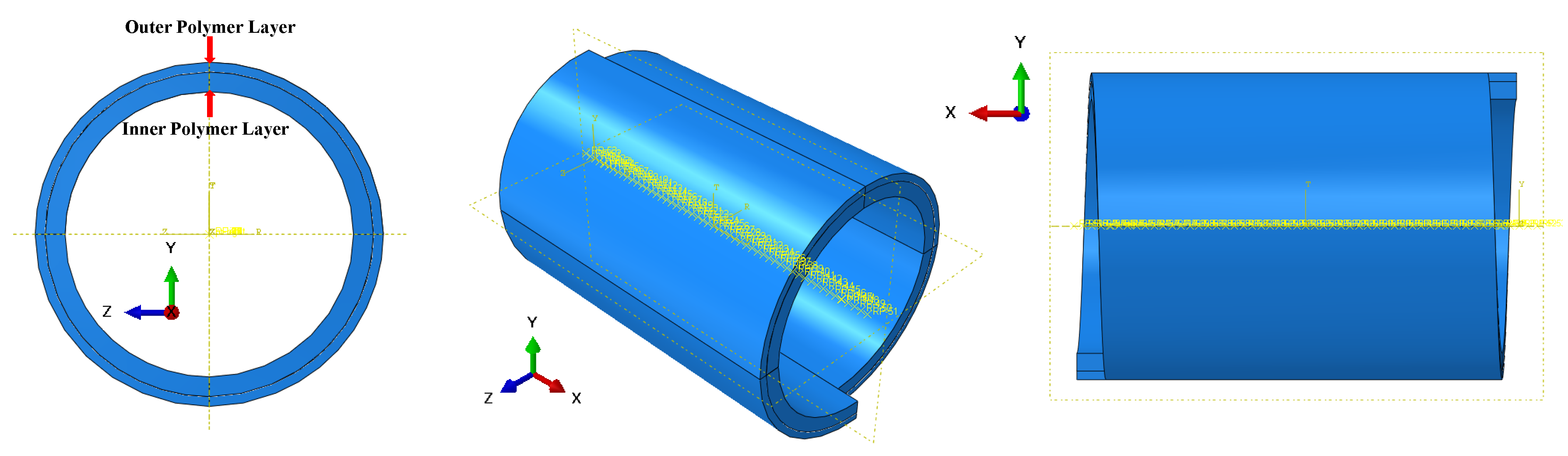
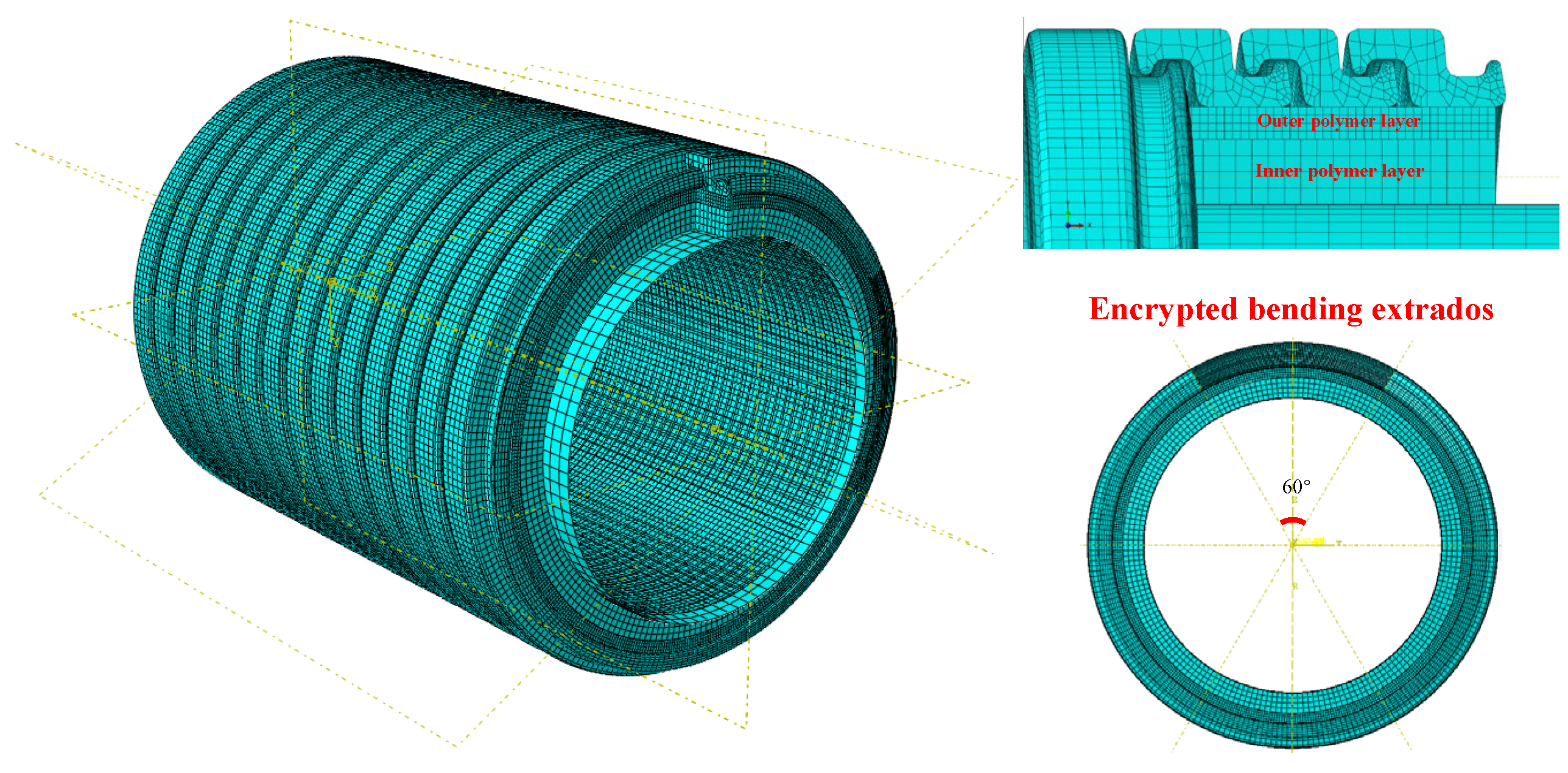
- Inner sheath: The polymer layer is split into two sub-layers to reduce the element count, as shown in Figure 6. The specific reasons are as follows: (1) the primary function of the polymer layer is to transmit the internal pressure effect to the pressure armour layer, and a mesh density difference along the wall thickness direction does not affect the transfer of pressure loads; (2) the impacts of polymer deformation and ingression under internal pressure should be considered during simulation. The inner coarse mesh transfers the internal pressure primarily, while the outer polymer layer with a finer mesh can better represent the polymer’s deformation and ingression effect on the pressure armour layer. This strategy of different mesh densities between two sub-layers of inner sheath (see Figure 7) enables the model to be functional and reduces the element. The inner layer possesses a 4 mm thickness and is assigned a 1 mm mesh size, and the outer layer is 2 mm thick with a 0.5 mm mesh size. The number of elements in the inner and outer layers is 71,448 and 312,200.
- Pressure armour layer: Under the premise of maintaining the global mesh size at 1 mm, the pressure armour layer is encrypted emphatically at the nub region and the bending extrados region, where the unlocking is expected to happen. The bending extrados side of the pressure armour layer is segmented along the ring direction by radians (see the low right corner of Figure 7). The mesh sizes of the master and slave self-contact surfaces of the pressure armour layer are 0.1 mm to 0.2 mm, respectively. For a 14.5-pitch model, the problem size is determined to contain 982,580 elements with 4,369,692 DOFs.
2.2.3. Boundary and Loading Conditions
- First step—pressurization: The first step focuses on applying internal pressure. The pressurization step allows the inner sheath to expand radially, transferring the pressure load to the pressure armour layer, which is essential for the replication of realistic interlayer interactions during riser production. A coupling constraint is applied at two extremities to limit pressure armour layer displacement during pressurization. Internal pressure is imposed on the internal surface of the sheath layer and increased linearly until the target value mimics the gradual pressurization in real-world scenarios.
- Second step—bending: This step replicates the overbending conditions that a flexible riser may experience during installation or after a birdcage failure. By applying a uniform curvature, the model captures the stress and deformation patterns in the pressure armour layer, which are critical for unlocking analysis. Within this step, a global uniform curvature is applied while maintaining a constant internal pressure. Predetermined displacements and rotations, which are calculated based on distances between specific reference points and the model’s midpoint, are imposed at specified reference points to ensure bending uniformity. The curvature is applied incrementally until the unlocking condition is achieved, as determined by the loss of interlock between adjacent armour wires.
2.2.4. Coupling and Boundary Condition Settings
- Simplified surface: Figure 8 depicts the schematic of the coupling constraint on the simplified surface. Two cross-sectional centres at the left and right ends of the simplified surface serve as the first and last reference points controlling the simplified surface. The remaining reference points are spaced out evenly at 2 mm intervals along the central longitudinal axis, matching the simplified surface mesh density. “Kinematic” coupling is adopted to constrain translational and rotational DOFs of the coupled nodes in the Cartesian coordinate system. Therefore, the simplified surface transforms into a deformation-controllable instance to achieve a uniformly bent configuration and transmit the curvature to other outer layers.
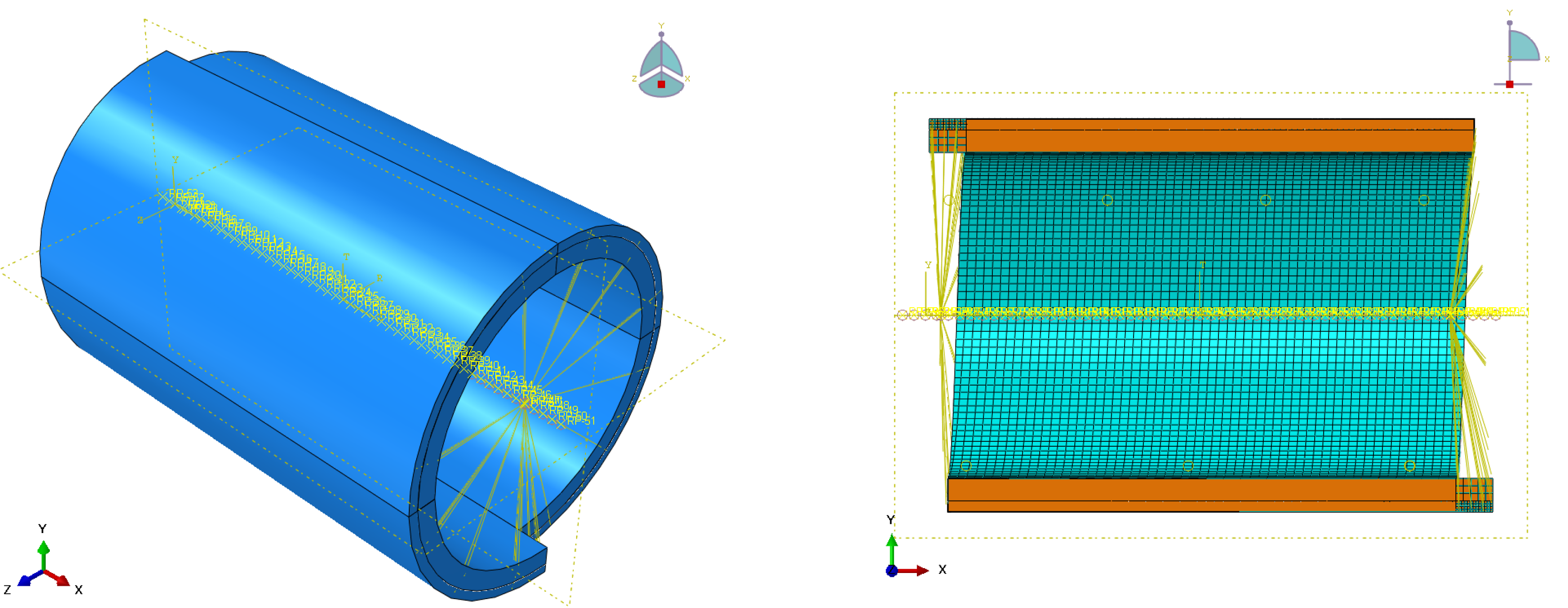
- Inner sheath: Figure 9 depicts the schematic of the coupling constraint on the inner sheath. Except for radial displacement U1, which permits the boundary of the inner sheath layer to radially expand under internal pressure, other DOFs are constrained with the reference points located at two extremities of the polymer layer.
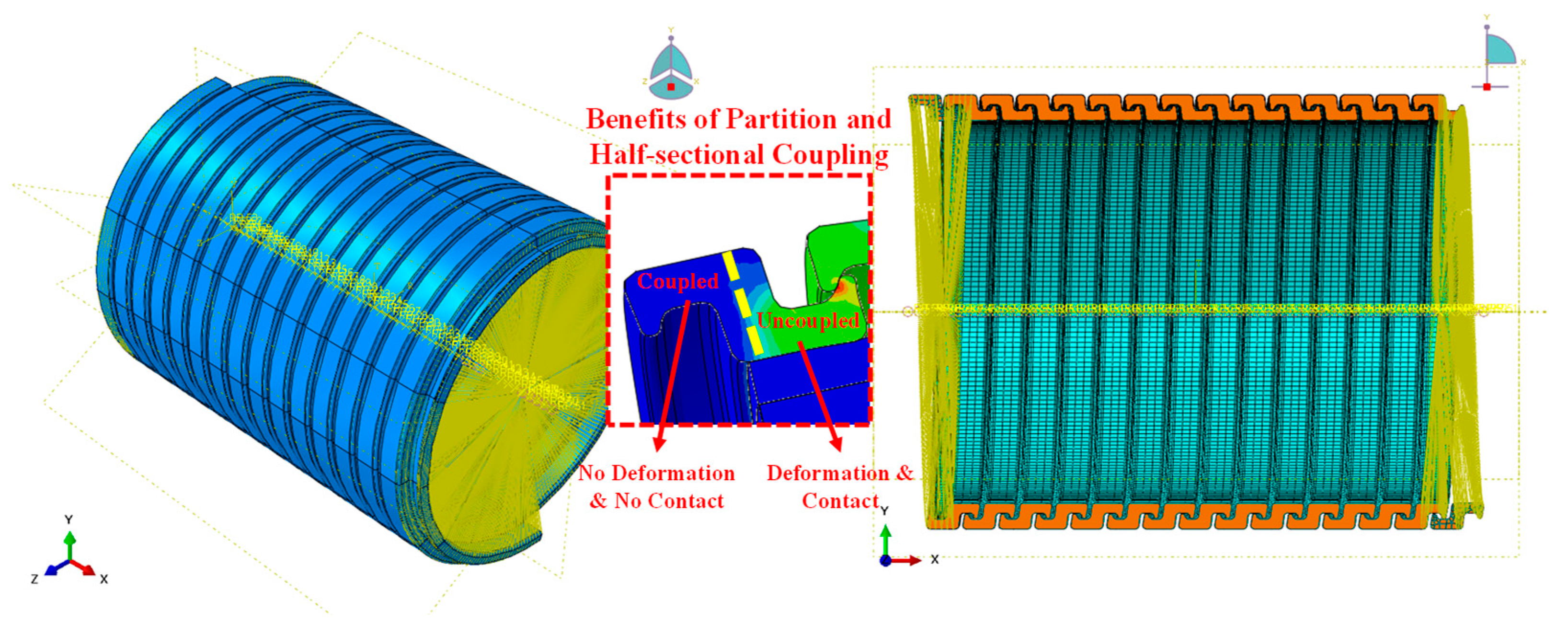
- Pressure armour layer: Figure 10 depicts the coupling constraint on the pressure armour wire. Pressure armour wire is coupled with two reference points at ends of the pressure armour layer. The half sectional coupling and purpose of the partition are shown in Figure 10. The cross-sectional profile is divided into two sections, as indicated by the yellow dot line. Throughout the entire simulation, the “coupled” portion in the armour wire will not contact the neighbouring armour wire and generate deformation. During the bending process, there will be significant contact and distortion effects in the “uncoupled” portion. Therefore, this method of splitting the profile into “coupled” and “uncoupled” sections will reduce the unexpected boundary effects brought on by the coupling constraints.
Uniform Bending Displacement Rotation Calculation Method

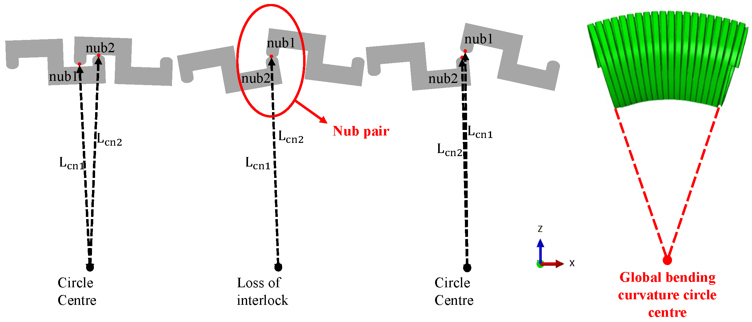
2.2.5. Unlocking Judgement Methodology
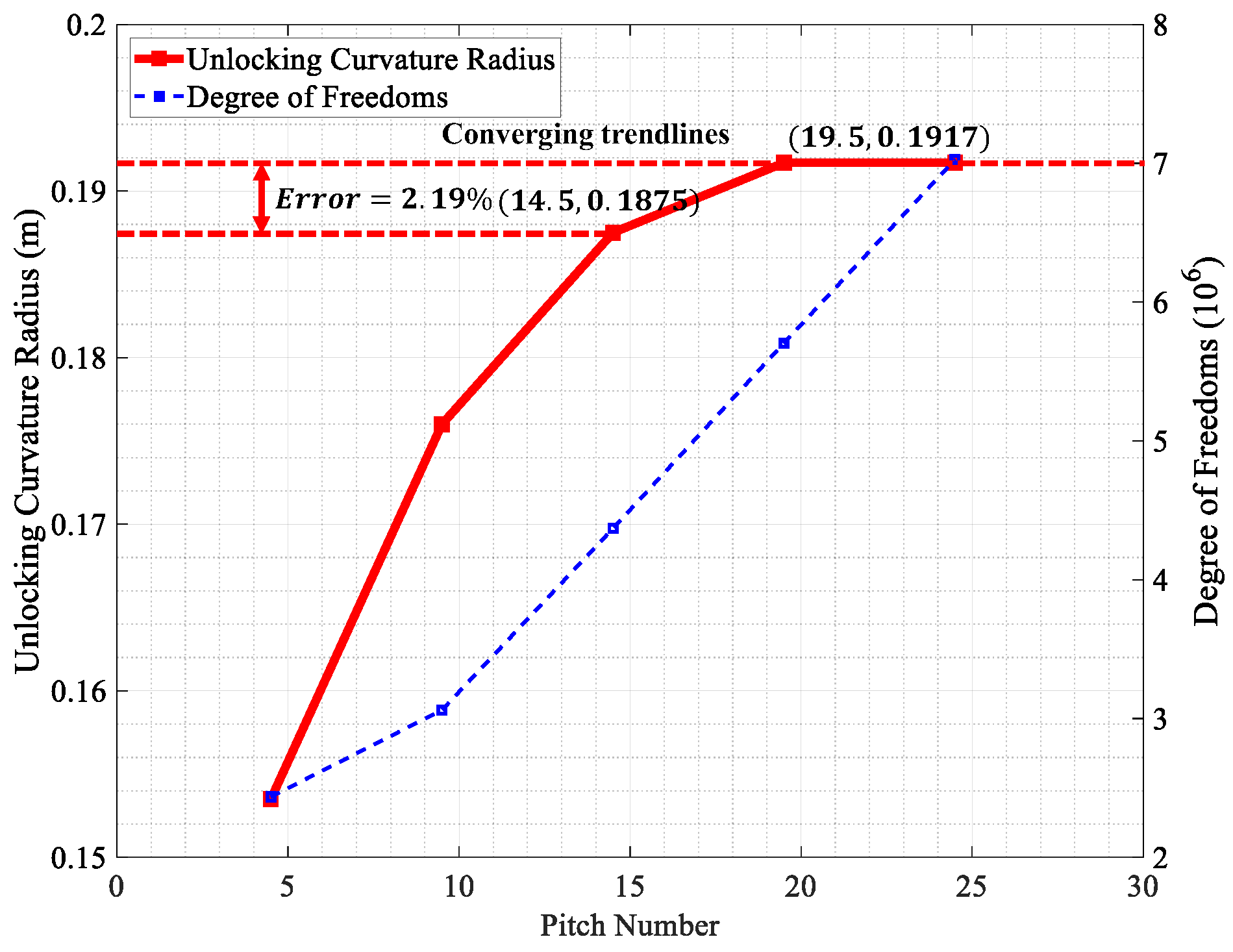
3. Pitch Number Sensitivity
4. Results and Discussion
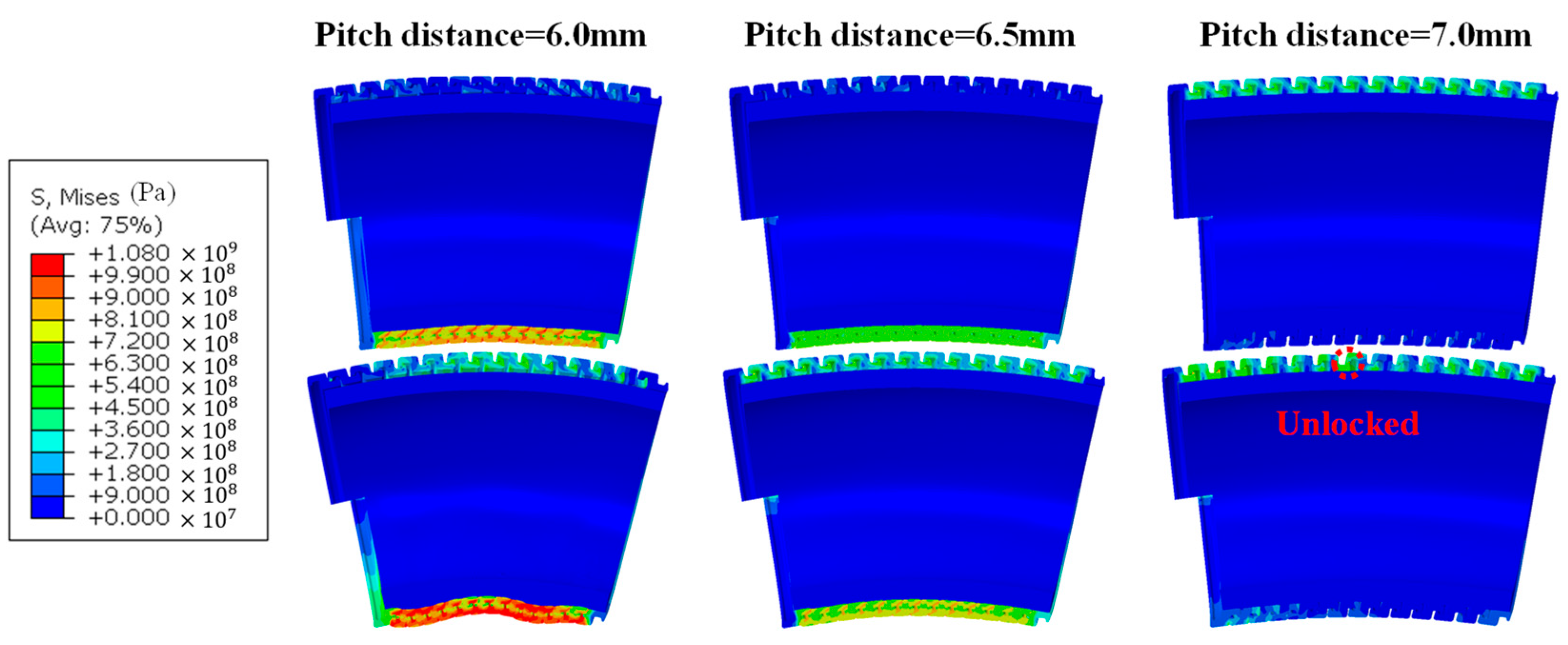
4.1. Influence of Pitch Distance
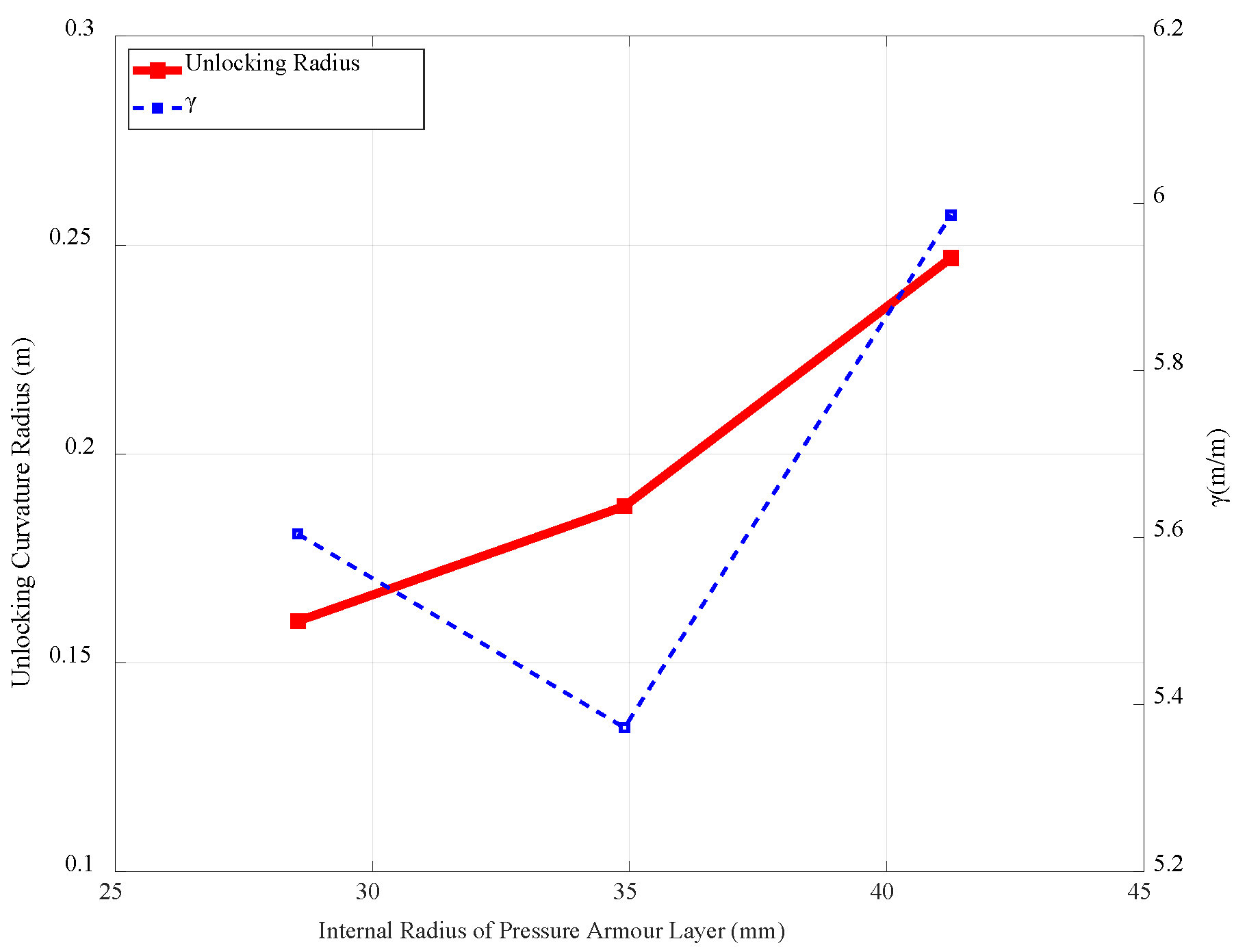
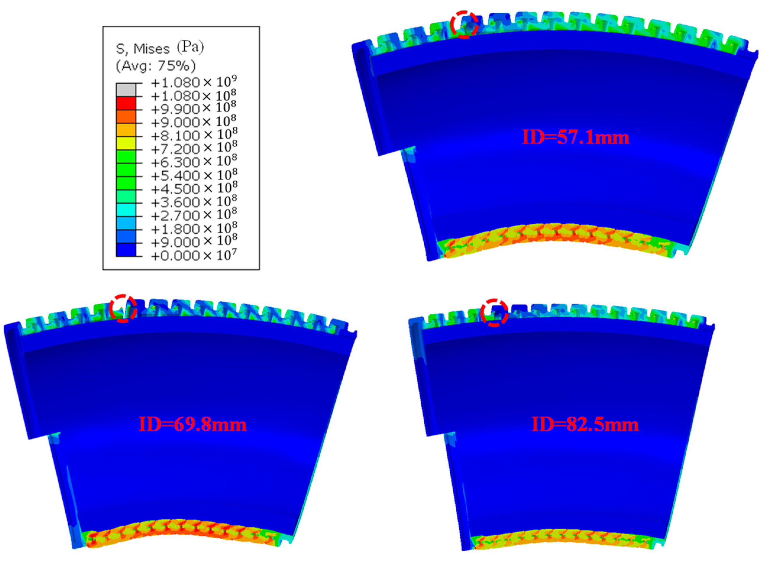
4.2. Influence of Pressure Armour Layer Internal Diameter
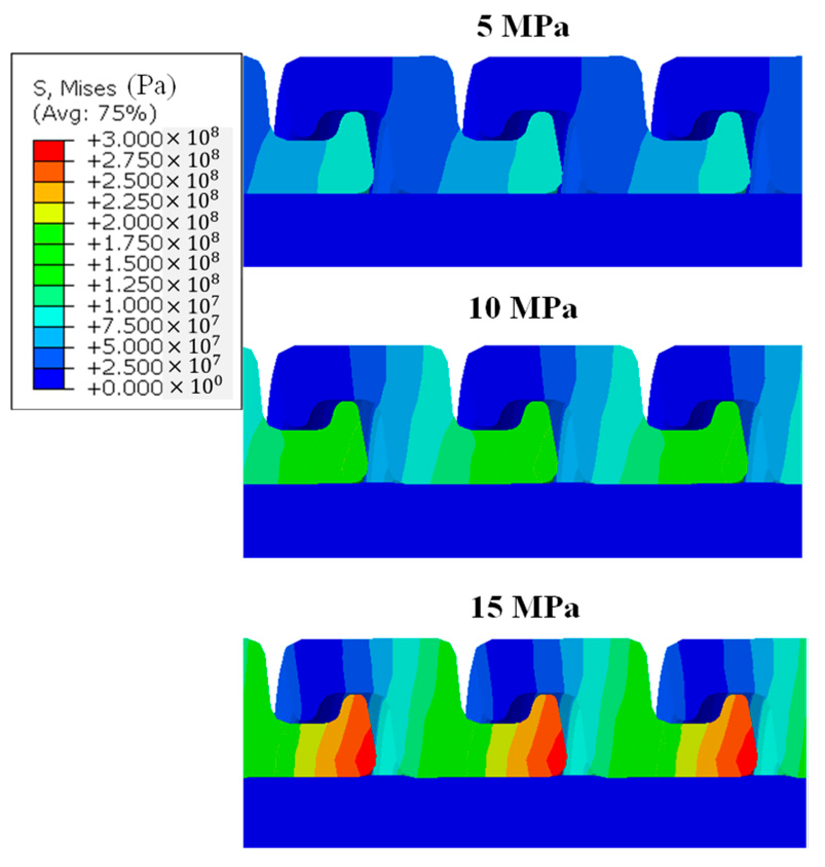
4.3. Influence of Internal Pressure
5. Conclusions and Perspective
Author Contributions
Funding
Institutional Review Board Statement
Informed Consent Statement
Data Availability Statement
Acknowledgments
Conflicts of Interest
Nomenclature
| Young’s modulus | |
| internal diameter | |
| pressure armour layer internal diameter | |
| unlocking curvature diameter | |
| distance between nub1 and the bending curvature centre | |
| distance between nub2 and the bending curvature centre | |
| hoop length of the FEM along the neutral axis | |
| overall length of the simplified surface | |
| sliding distance between two adjacent nubs at the initial unbent state | |
| as the total number of reference points on one side of the FEM | |
| critical bending curvature that will trigger the unlocking | |
| extrados curvature radius | |
| minimum curvature radius applied in the FEM | |
| standing for the reference point at the model extremities | |
| real simulation time | |
| pressure armour layer thickness | |
| total simulation time of the overbending analysis step | |
| Poisson ratio | |
| yielding stress | |
| ultimate tensile strength | |
| ultimate tensile strain | |
| material density | |
| elastoplastic deformation contributed by each nub pair after being stretched and making contact for the unlocking | |
| global bending radians | |
| difference between distances of the two adjacent nubs to be unlocked with the bending curvature centre | |
| traction displacement required for the extrados unlocking | |
References
- Stigerørskader-Skader Og Hendelser Fra Petroleumstilsynets CODAM Database. Available online: https://www.havtil.no/contentassets/a13ec8ed3fc94e3a97b76aebb01bf6e3/stigeroersskader-2021-okt.pdf (accessed on 28 July 2021).
- Muren, J. PSA-NORWAY Flexible Pipes Failure Modes, Inspection, Testing and Monitoring. 2007. Available online: https://www.ptil.no/contentassets/a4c8365164094826a24499ef9f22742b/p5996rpt01rev02cseaflex_janmuren.pdf (accessed on 1 December 2007).
- Simonsen, A. Inspection and Monitoring Techniques for Un-Bonded Flexible Risers and Pipelines. Master’s Thesis, University of Stavanger, Stavanger, Norway, 2014. [Google Scholar]
- Fergestad, D.; Løtveit, S.A. Handbook on Design and Operation of Flexible Pipes; SINTEF Ocean: Trondheim, Norway, 2014; Volume 1, ISBN 9788271742652. [Google Scholar]
- API. 17J Specification for Unbonded Flexible Pipe; American Petroleum Institute: Washington, DC, USA, 2002. [Google Scholar]
- Ted Miller, FPSO Past Issues and Typical Claims 2012. Available online: https://slideplayer.com/slide/1567408/ (accessed on 28 July 2021).
- Li, X.; Vaz, M.A.; Custódio, A.B. Analytical Study of a Repair Methodology for Flexible Pipes Anti-Birdcage Tapes. Mar. Struct. 2019, 63, 289–303. [Google Scholar] [CrossRef]
- Lu, J.; Tan, Z.; Ma, F.; Sheldrake, T. Simulating Contact Behavior Between the Flexlok Wires. In International ANSYS Conference; Wellstream International Limited: Newcastle upon Tyne, UK, 2008. [Google Scholar]
- Lu, J.; Ma, F.; Tan, Z.; Sheldrake, T. The Impact of Flexbarrier Ingress on Flexlok Stress. In Proceedings of the ASME 2009 28th International Conference on Ocean, Offshore and Arctic Engineering, Honolulu, HI, USA, 31 May–5 June 2009; Volume 3, pp. 533–538. [Google Scholar]
- Neto, A.G.; Martins, C.D.A.; Pesce, C.P.; Meirelles, C.O.C.; Malta, E.R.; Neto, T.F.B.; Godinho, C.A.F. Prediction of Burst in Flexible Pipes. J. Offshore Mech. Arct. Eng. 2013, 135, 011401. [Google Scholar] [CrossRef]
- Neto, A.G.; Martins, C.D.A.; Pesce, C.P.; Meirelles, C.O.C.; Malta, E.R.; Barbosa Neto, T.F.; Godinho, C.A.F. Burst Prediction of Flexible Pipes. In Proceedings of the 29th International Conference on Ocean, Offshore and Arctic Engineering, Shanghai, China, 6–11 June 2010; Volume 5, pp. 511–520. [Google Scholar]
- Cuamatzi-Melendez, R.; Castillo-Hernández, O.; Vázquez-Hernández, A.O.; Albiter, A.; Vaz, M. Finite Element Modeling of Burst Failure in Unbonded Flexible Risers. Eng. Struct. 2015, 87, 58–69. [Google Scholar] [CrossRef]
- Liu, X.; Qu, Z.; Liu, Y.; He, J.; Si, G.; Wang, S.; Liu, Q. Numerical Simulation of Burst Failure in 2.5-Inch Unbonded Flexible Riser Pressure Armor Layers. Metals 2024, 14, 762. [Google Scholar] [CrossRef]
- Paumier, L.; Averbuch, D.; Felix-Henry, A. Flexible Pipe Curved Collapse Resistance Calculation. In Proceedings of the ASME 2009 28th International Conference on Ocean, Offshore and Arctic Engineering, Honolulu, HI, USA, 31 May–5 June 2009; Volume 3, pp. 55–61. [Google Scholar]
- Paumier, L.; Mesnage, O. PSI Armour Wire for High Collapse Performance of Flexible Pipe. In Proceedings of the ASME 2011 30th International Conference on Ocean, Offshore and Arctic Engineering, Rotterdam, The Netherlands, 19–24 June 2011; Volume 4, pp. 239–246. [Google Scholar]
- API. 17B Recommended Practice for Flexible Pipe; American Petroleum Institute: Washington, DC, USA, 2008. [Google Scholar]
- Neto, A.G.; de Arruda Martins, C.; Malta, E.R.; Godinho, C.A.; Neto, T.F.; de Lima, E.A. Wet and Dry Collapse of Straight and Curved Flexible Pipes: A 3D FEM Modeling. In Proceedings of the Twenty-Second International Offshore and Polar Engineering Conference, Rhodes, Greece, 17–22 June 2012. [Google Scholar]
- Neto, A.G.; Martins, C.D.A.; Malta, E.R.; Tanaka, R.L.; Godinho, C.A.F. Simplified Finite Element Models to Study the Dry Collapse of Straight and Curved Flexible Pipes. J. Offshore Mech. Arct. Eng. 2016, 138, 021701. [Google Scholar] [CrossRef]
- Neto, A.G.; Martins, C.D.A.; Malta, E.R.; Tanaka, R.L.; Godinho, C.A.F. Simplified Finite Element Models to Study the Wet Collapse of Straight and Curved Flexible Pipes. J. Offshore Mech. Arct. Eng. 2017, 139, 061701. [Google Scholar] [CrossRef]
- Cuamatzi-Melendez, R.; Castillo-Hernández, O.; Vázquez-Hernández, A.O.; Vaz, M.A. Finite Element and Theoretical Analyses of Bisymmetric Collapses in Flexible Risers for Deepwaters Developments. Ocean. Eng. 2017, 140, 195–208. [Google Scholar] [CrossRef]
- Zhu, X.; Lei, Q. Collapse Characteristics of Flexible Pipes under External Pressure. J. Braz. Soc. Mech. Sci. Eng. 2021, 43, 312. [Google Scholar] [CrossRef]
- Yun, R.-H.; Jang, B.-S.; Kim, J. Du Improvement of the Bending Behavior of a Flexible Riser: Part I—Nonlinear Bending Behavior Considering the Shear Deformation of Polymer Layers. Appl. Ocean Res. 2020, 101, 102204. [Google Scholar] [CrossRef]
- Ruan, W.; Chen, M.; Nie, Q.; Xu, P.; Li, J.; Wang, X. Dynamic Response of Steel Lazy Wave Riser Considering the Excitation of Internal Solitary Wave and Ocean Currents. Ocean Eng. 2024, 294, 116708. [Google Scholar] [CrossRef]
- Ruan, W.; Nie, Q.; Han, X.; Li, J.; Bai, Y.; Fu, X. Accurate Modeling and Safety Evaluation of Dented Pipeline with Internal Pressure Based on Reverse Modeling Technique. Ships Offshore Struct. 2024, 1–11. [Google Scholar] [CrossRef]
- Liu, Q.; Xue, H.; Tang, W. Behavior of Unbonded Flexible Riser with Composite Armor Layers under Coupling Loads. Ocean Eng. 2021, 239, 109907. [Google Scholar] [CrossRef]
- Liu, Q.; Xue, H.; Tang, W.; Yuan, Y. Theoretical and Numerical Methods to Predict the Behaviour of Unbonded Flexible Riser with Composite Armour Layers Subjected to Axial Tension. Ocean Eng. 2020, 199, 107038. [Google Scholar] [CrossRef]
- Liu, Q.-S.; Qu, Z.-Y.; Wang, G.; He, J.-W.; Ni, J.-F. Advanced Analysis of Cross-Sectional Properties in Unbonded Flexible Risers with Composite Layers. Ships Offshore Struct. 2025, 1–14. [Google Scholar] [CrossRef]
- Merino, H.E.M.; de Sousa, J.R.M.; Magluta, C.; Roitman, N. Numerical and Experimental Study of a Flexible Pipe Under Torsion. In Proceedings of the 29th International Conference on Ocean, Offshore and Arctic Engineering, Shanghai, China, 6–11 June 2010; Volume 5, pp. 911–922. [Google Scholar]
- O’Halloran, S.M.; Connaire, A.D.; Harte, A.M.; Leen, S.B. Modelling of Fretting in the Pressure Armour Layer of Flexible Marine Risers. Tribol. Int 2016, 100, 306–316. [Google Scholar] [CrossRef]
- Dong, L.; Huang, Y.; Zhang, Q.; Liu, G. An Analytical Model to Predict the Bending Behavior of Unbonded Flexible Pipes. J. Ship Res. 2013, 57, 171–177. [Google Scholar] [CrossRef]


| Layer | ID (mm) | Thickness (mm) | (GPa) | (MPa) | (MPa) | Material | (Kg/m3) | Pitch (mm) | ||
|---|---|---|---|---|---|---|---|---|---|---|
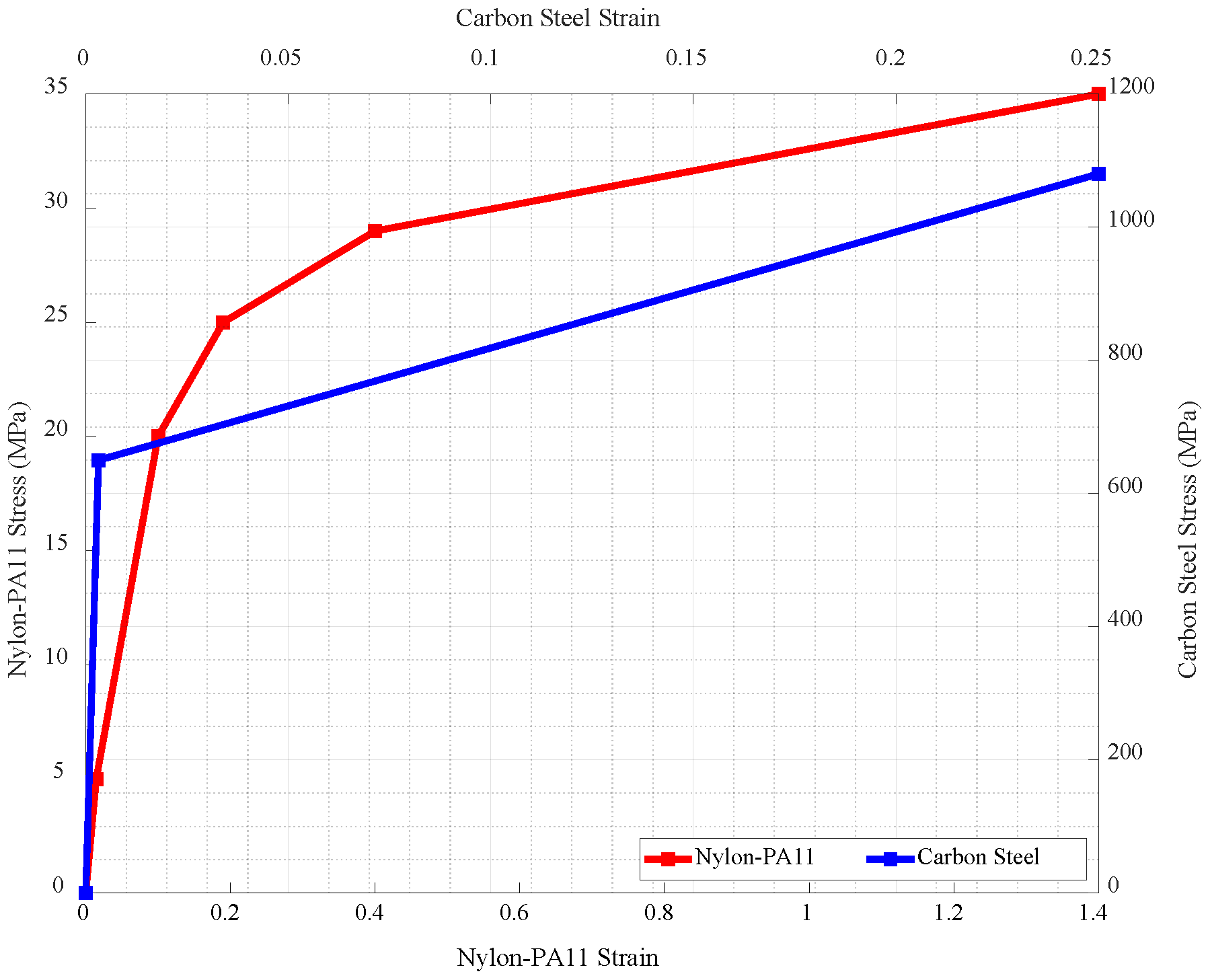
| Inner sheath | 57.8 | 6 | 0.345 | 0.3 | N/A | 35 | 1.4 | Nylon PA11 | 1040 | N/A |
| Pressure armour | 69.8 | 4.8 | 207 | 0.3 | 650 | 1080 | 0.25 | Carbon Steel | 7850 | 6.5 |
| Contact Pair | Master–Slave Assignment | Surface Domain | COF | Smoothing Option |
|---|---|---|---|---|
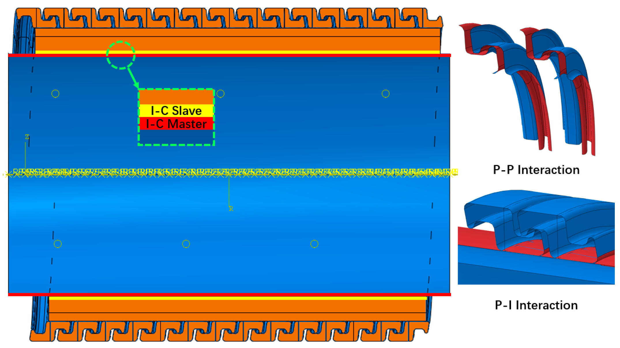
| P-P | Master | 2–12 | 0.3 | Spherical |
| Slave | 14–24 | Spherical | ||
| P-I | Master | 12–14 | 0.1 | Spherical |
| Slave | Outer surface of inner sheath | Revolution | ||
| I-C | Master | Outer surface of carcass | 0 | Revolution |
| Slave | Inner surface of inner sheath | Revolution |
Disclaimer/Publisher’s Note: The statements, opinions and data contained in all publications are solely those of the individual author(s) and contributor(s) and not of MDPI and/or the editor(s). MDPI and/or the editor(s) disclaim responsibility for any injury to people or property resulting from any ideas, methods, instructions or products referred to in the content. |
© 2025 by the authors. Licensee MDPI, Basel, Switzerland. This article is an open access article distributed under the terms and conditions of the Creative Commons Attribution (CC BY) license (https://creativecommons.org/licenses/by/4.0/).
Share and Cite
Wei, R.; Li, X.; Vaz, M.A.; Custódio, A.B. Finite Element Modelling of Pressure Armour Unlocking Failure in Unbonded Flexible Risers. J. Mar. Sci. Eng. 2025, 13, 411. https://doi.org/10.3390/jmse13030411
Wei R, Li X, Vaz MA, Custódio AB. Finite Element Modelling of Pressure Armour Unlocking Failure in Unbonded Flexible Risers. Journal of Marine Science and Engineering. 2025; 13(3):411. https://doi.org/10.3390/jmse13030411
Chicago/Turabian StyleWei, Rongzhi, Xiaotian Li, Murilo Augusto Vaz, and Anderson Barata Custódio. 2025. "Finite Element Modelling of Pressure Armour Unlocking Failure in Unbonded Flexible Risers" Journal of Marine Science and Engineering 13, no. 3: 411. https://doi.org/10.3390/jmse13030411
APA StyleWei, R., Li, X., Vaz, M. A., & Custódio, A. B. (2025). Finite Element Modelling of Pressure Armour Unlocking Failure in Unbonded Flexible Risers. Journal of Marine Science and Engineering, 13(3), 411. https://doi.org/10.3390/jmse13030411