Article

Multi-View and Multi-Type Feature Fusion Rotor Biofouling Recognition Method for Tidal Stream Turbine

1
Logistics Engineering College, Shanghai Maritime University, Shanghai 201306, China
2
Institut de Recherche Dupuy de Lôme (UMR CNRS 6027), University of Brest, 29238 Brest, France
*
Author to whom correspondence should be addressed.
J. Mar. Sci. Eng. 2025, 13(2), 356; https://doi.org/10.3390/jmse13020356
Submission received: 18 January 2025 / Revised: 7 February 2025 / Accepted: 10 February 2025 / Published: 15 February 2025

Abstract

:
Power generation is affected and structural instability may occur when biofouling attaches to the rotor of tidal stream turbines (TSTs). Image signals are used to identify biofouling for biofouling recognition, thus achieving on-demand maintenance, optimizing power generation efficiency, and minimizing maintenance costs. However, image signals are sensitive to background interferences, and underwater targets blend with the water background, making it difficult to extract target features. Changes in water turbidity can affect the effectiveness of image signal biofouling recognition, which can lead to reduced recognition accuracy. In order to solve these problems, a multi-view and multi-type feature fusion (MVTFF) method is proposed to recognize rotor biofouling on TSTs for applications in TST operation and maintenance. (1) Key boundary and semantic information are captured to solve the problem of background feature interference by comparing and fusing the extracted multi-view features. (2) The local geometric description and dependency are obtained by integrating contour features into multi-view features to address the issue of the target mixing with water. The mIoU, mPA, Precision, and Recall of the experimental results show that the method achieves superior recognition performance on TST datasets with different turbidity levels.

1. Introduction

At present, the world faces two serious problems: energy shortages and climate change. The massive use of fossil fuels has brought about serious environmental problems, such as atmospheric contamination, water scarcity, contaminated soil, environmental degradation, and extensive human health issues [1]. In view of these two serious problems, it is urgent to adjust the existing energy structure to reduce the dependence on fossil fuels. Marine renewable energy has become the focus of national research and development due to its rich, renewable, and non-polluting characteristics [2,3]. Tidal stream turbines (TSTs) are anticipated to become an environmentally friendly and renewable energy power generation method, belonging to the category of marine renewable energy converters, that does not emit greenhouse gases during normal operation [4].
Due to the complex underwater environment around TSTs, rotor biofouling is likely to be observed, including cavitation, severe rusting, biofouling by sea floor organisms, and abrasion or even breakage of the rotors. Meanwhile, variations in the power coefficients ( C p ) of the rotor at the same velocity are caused by biofouling [5], and the energy conversion efficiency of a TST is affected by various types of pollution [6,7,8]. At present, the maintenance mechanism of TSTs involves deploying divers underwater or lifting the entire machine out of the sea for inspection and repair at regular intervals. This process incurs high maintenance costs and has become one of the factors restricting the development of tidal power generation [9]. Effective recognition technology is of great practical significance for promoting on-demand maintenance of TSTs, ensuring safe and efficient operation, and reducing maintenance costs. Therefore, research into TST rotor biofouling recognition technology is key to improving the reliability and safety of TSTs, and is also an urgent need for developing tidal energy demonstrations.
The electrical signals generated by TSTs with biofouling contain various biofouling characteristics, which allows biofouling recognition to be performed through these signals. However, the information within the electrical signals is limited, and the biofouling characteristics are not clearly identifiable. In addition, factors such as surges, turbulence, and instantaneous flow rate variations in the underwater environment [10] can obscure the feature signals [5], resulting in recognition failures. Biofouling locations can be efficiently and accurately recognized by processing images or video signals captured by underwater image sensors, which facilitates real-time maintenance.
Image signal-based biofouling recognition methods for TSTs are currently divided into two main categories: classification networks and semantic segmentation networks. The degree of biofouling can be assessed using classification networks. Zheng et al. [11] propose a recognition method for recognize attachments on TST rotors based on a sparse auto-encoder and Softmax regression. This method can accurately recognize rotor attachments and has achieved a high recognition accuracy by extracting features and performing classification. Xin et al. [12] utilized depthwise separable convolutions [13] instead of sparse auto-encoders to classify more complex attachment cases. The classification networks can recognize the type of attachment on the TST rotor, but cannot directly provide detailed information such as the degree, biofouling area, and location.
Peng et al. [14] propose an adaptive coarse-fine semantic segmentation method. This method adaptively fuses a coarse branch that performs global segmentation and a fine branch that obtains local contours based on their respective weights. The final segmentation map is then output through a Softmax layer. Qi et al. [15] propose a semantic segmentation method based on image entropy weighted spatio-temporal fusion. This method improves robustness to rotational speed changes and achieves superior recognition performance at different rotational speeds through spatio-temporal feature fusion and image entropy weighting mechanism. Yang et al. [16] propose a method based on asymmetric depthwise convolution and convolution block attention module. Asymmetric depthwise convolution is used in this method to reduce convolution computation, and the convolution block attention module is applied to minimize redundant information. Chen et al. [17] propose a semi-supervised video segmentation network to recognize attachments in underwater video sources. This method uses a generator to output a recognition map, and uses a conditional discriminator to calculate the pixel-by-pixel recognition confidence to quickly and accurately identify labeled and unlabeled images under medium- and high-rotation-speed images. Rashid et al. [18] propose a soft voting ensemble transfer learning-based. This method integrates critical steps such as data augmentation, data pre-processing, and data segmentation for enhanced performance. Due to the complex and variable underwater environment, the above existing biofouling recognition methods can easily be interfered with by the negative factors of the background or surroundings. Also, the features of the water are present everywhere in the whole image, making it very difficult to distinguish objects, resulting in different degrees of blurring of the acquired TST images; this leads to a loss of features and blurring of the edge and texture features. Consequently, this reduces the accuracy of classification and semantic segmentation significantly. In order to address this issue, a biofouling recognition method based on multi-view and multi-type feature fusion (MVTFF) has been proposed.
The main contribution of this paper is summarized as follows:
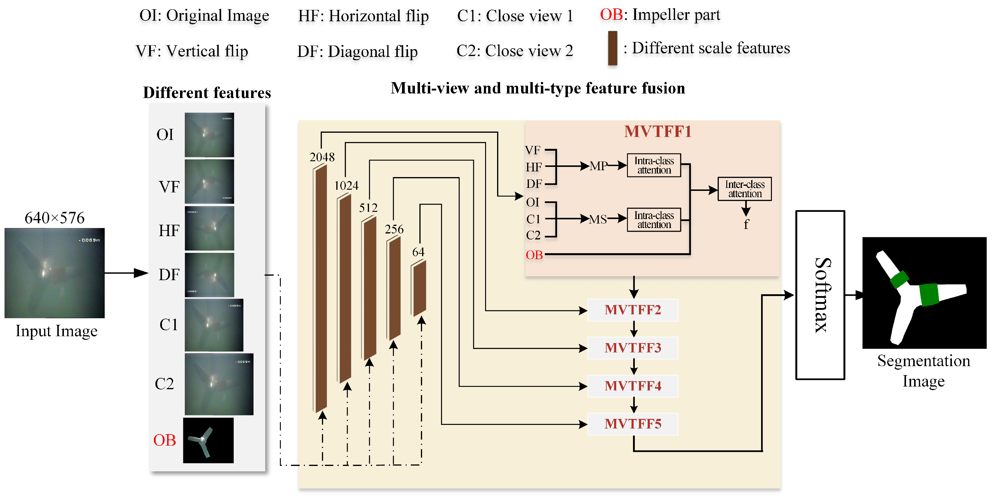
  • A semantic segmentation method based on MVTFF is proposed for TST biofouling recognition, aiming to improve the accuracy of TST biofouling recognition in turbid environments.
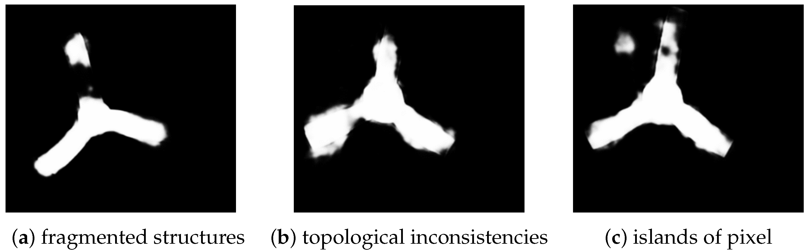
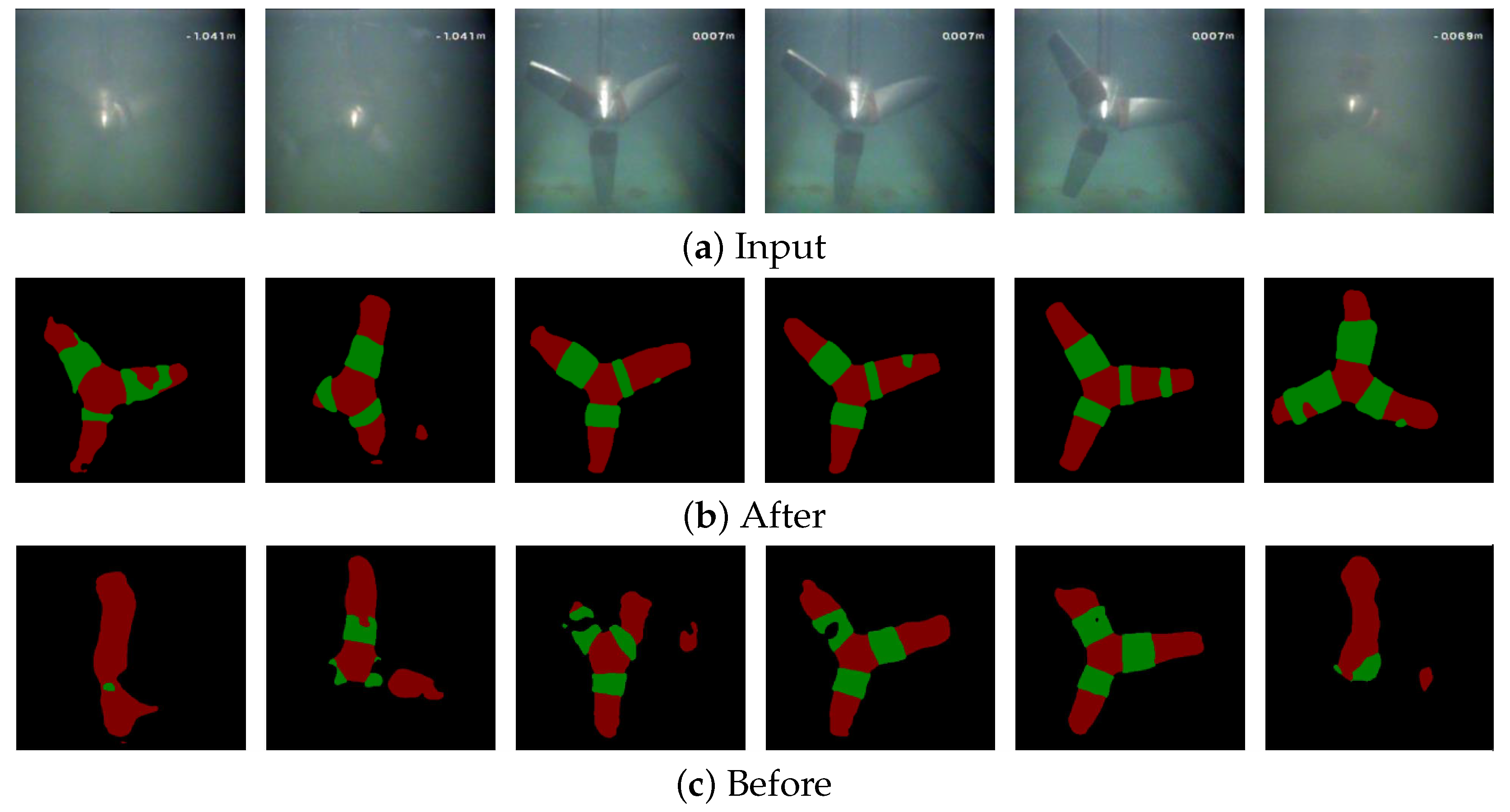
  • The rotor contour features are extracted by explicit shape priors, which is conducive to more accurate positioning and recognition of targets.
  • We enhance semantic information by integrating and interacting different perspectives and different types of features to improve semantic segmentation effects.

2. Problem Description

The challenges in underwater object detection and recognition can be summarized as follows [19]: (1) Limited underwater image datasets: The complex underwater environment places high demands on imaging equipment, making underwater images harder to acquire than atmospheric optical images. This creates difficulty for data-driven deep learning models to produce satisfactory results. (2) Quality issues of underwater images: Underwater images often suffer from uneven lighting, blurring, fog, low contrast, and color distortion [20,21,22,23,24], resulting in poorer performance compared to atmospheric optical images in terms of color and texture information. (3) Small and clustered targets: Many underwater objects are small and often clustered together, making it difficult to capture detailed information. (4) Imbalanced distribution of underwater targets: The imbalanced distribution of target classes underwater makes it difficult for object detectors to effectively learn the features of underrepresented classes, which negatively impacts detection performance.
The above problems also exist for TST rotor biofouling recognition; the TST rotor dataset suffers from insufficient data and class imbalance. There is an aggregation of attachments on the TST rotor and some of the biofouling is small compared to the whole image. Meanwhile, the underwater environment contains a large number of suspended particles, such as plankton and sediment raised by the TST, which cause light scattering [25]. In addition, since water serves as the medium for light propagation, light is attenuated during the propagation process [26]. These factors not only reduce image clarity but also weaken the edge features of objects in the image. As a result, semantic segmentation networks face difficulties in accurately extracting features, leading to decreased recognition accuracy and even recognition failure. Moreover, the underwater environment is complex and variable, and the existing biofouling recognition methods are easily interfered by the negative factors of the background and surroundings. This results in varying degrees of blurring in the acquired TST images, leading to feature loss and the blurring of edge and texture features. This reduces the accuracy of classification and semantic segmentation significantly, as shown in Figure 1.
Another problem is the inter-class similarity between different objects and the background due to similar appearance and camouflage types. The features of the water are present everywhere in the whole image and mixed with all the other features since the TST rotor is running underwater. This inter-class similarity makes it highly infeasible to distinguish these objects, as current methods are easily distracted by negative factors from deceptive backgrounds and surroundings. As a result, discriminative and fine-grained semantic cues of the objects are difficult to extract, making it challenging to accurately segment the objects and predict uncertain regions from a confusing background.
In summary, the MVTFF method is proposed to solve the problem that existing biofouling recognition methods in TST rotor biofouling recognition are easily interfered with by the negative factors of the background and surroundings, as well as the problem of inter-class similarity between different objects and backgrounds due to similarities in appearance and camouflage types.

3. MVTFF-Based Biofouling Recognition for TST Rotor

3.1. Basic Process of MVTFF

Figure 2 is the basic structure of the MVTFF network proposed in this paper. For the input image O I R H × W × 3 , images at different angles are obtained through horizontal flipping, vertical flipping, and mirror flipping; images at different distances are obtained through resizing; and images that retain only the rotor area are obtained using the fillPoly function of OpenCV. The Feature Pyramid Network (FPN) [27] was originally designed for target detection, so using FPN to extract features at five different scales from the input image, with the RESNET model as the backbone extractor, these feature maps can be fused. The main idea of FPN is to establish a feature pyramid to obtain multi-scale feature representations, in order to handle targets of different sizes and shapes better. After multi-scale feature extraction, the five scales of eight images including the original image are input into the MVTFF module for processing, and the output of each MVTFF module is fused to obtain the final feature map. The structural parameters of the MVTFF module are given in Table 1.
During the training process, a segmentation mask is obtained by the weighted combination of a set of candidates from source images, referred to as registration bases. This mask is used as a shape prior to aid in the segmentation of the target image. This approach enhances the accuracy of target localization and recognition by utilizing images that retain only the rotor region, thereby enabling the extraction of the rotor’s contour features.
During the fusion process, the MVTFF module was proposed to interact and fuse the different views of images through an intra-class attention mechanism and inter-class attention mechanism. The description of the proposed MVTFF module will be provided in Section 3.3.

3.2. Explicit Shape Prior for Training Process

In the image segmentation, the overdependence of fully convolutional deep neural networks and their variants on pixel-level classification and regression has been identified early on as a problem [28]. These methods are prone to generate segmentation artifacts such as fragmented structures, topological inconsistencies, and islands of pixels, as shown in Figure 3. Using prior knowledge in traditional image segmentation algorithms is very useful for obtaining more accurate and plausible results [29].
The learnable explicit shape priors are incorporated into the neural networks by combining them with the original image as input. The network outputs consist of predicted masks and attention maps. The channels of the attention map provide shape information for the ground truth region of the data. The explicit shape priors model can be described as follows:
y t e s t , a t t e n t i o n = F ( x t e s t , S ( x t r a i n , y t r a i n ) )
where F is the forward propagation during testing, and S is a continuous shape prior for constructing the mapping between image space and label space. x t r a i n and y t r a i n are the input–output pairs used during training, while x t e s t and y t e s t are used for testing and evaluation of the model’s performance after training. During the training process, the shape prior S is updated alongside the pairing of images and their corresponding labels. Shape priors are derived from input images and labels to enhance the mapping of images to their corresponding labels. After training, the shape prior is fixed for testing. During testing, the fixed shape prior is dynamically adjusted to better align with the input images, improving the accuracy of label mapping. This adjustment enhances the model’s performance and robustness, enabling it to handle variations in input images more effectively and achieve higher classification or recognition accuracy. Additionally, the shape prior assists in focusing on regions of interest while suppressing background areas, similar to attention maps. Minor inaccuracies in the shape prior do not significantly affect the model’s learning process.
It is beneficial to promote a more accurate segmentation of the target image by using the weighted combination of the segmentation masks of a portion of the source images as the shape prior. This is shown as follows:
y t e s t = i = 1 m α i × ϕ ( y i ; T ( x i x t e s t ) ) , x i x t r a i n , y i y t r a i n
where x t r a i n and x t e s t are images from training and testing datasets, y t r a i n and y t e s t are ground truths from training and testing datasets, x i and y i are the selected source images and ground truths, α i is the weighting coefficient, T represents the registration transform between x i and x t e s t , and ϕ is the transformation matrix that applies the registration transform to each ground truth of y i .

3.3. Multi-View and Multi-Type Feature Fusion

Inspired by [30], the multi-view and multi-type feature fusion (MVTFF) module consists of an intra-class attention mechanism and inter-class attention mechanism. Supplementing the boundary information with the features from different viewing angles enhances the semantic information with features from different viewing distances; it is important to focus the model on the rotor area with contour features.
The purpose of the intra-class attention mechanism is to aggregate image information from different distances and different viewing angles separately. Taking three feature tensors O I , C 1 , and C 2 at different distances as an example, the input feature tensors are processed through convolution and activation operations. Adaptive average pooling and adaptive maximum pooling operations are performed on C 1 and C 2 , with their scales adjusted to match the target scale. This process maintains the spatial structure of the features and allows the fused features to align more effectively with the target features. These features are concatenated along the channel dimension to form an initial feature tensor:
f d i s = R e L U ( C o n v ( C a t ( O I , C 1 , C 2 ) ) )
where C a t ( ) is the concatenation operation along channel and R e L U ( ) is the activation function.
Attention weights t a , t b , and t c are calculated for each feature tensor. The weights are obtained as follows:
t a = σ ( f d i s × 1 T a 1 × 2 T a 2 × 3 T a 3 )
t b = σ ( f d i s × 1 T b 1 × 2 T b 2 × 3 T b 3 )
t c = σ ( f d i s × 1 T c 1 × 2 T c 2 × 3 T c 3 )
where T a i , T b i , and T c i are the parameter matrix of attention factor calculation modules based on the tensor multiple modulus multiplication operation, × i represents modular multiplication [31], and the Sigmoid function σ is used to normalize the weights.
The attention weights are applied to the corresponding features. The weighted features are fused to generate the first-stage fused feature MP:
M P = O I t a + C 1 t b + C 2 t c
where t a , t b , and t c are attention, and ⊙ is element-by-element multiplication.
Similarly, the features of images with different viewing angles are fused through the same operation. The channel attention module and spatial attention module are applied to enhance the representation ability of specific region shapes for multi-angle features. The semantic information of multi-angle and multi-distance feature maps is enhanced by using the two intra-class attention feature fusion modules.
The inter-class attention mechanism aims to interact with multi-angle features, multi-distance features, and rotor contour features. M P , M S , and O B are fused to obtain the final output of the MVTFF module. Taking MP as an example, the tensor M P is enhanced by applying the mix pooling. Mix pooling combines the advantages of maximum pooling and average pooling, and its formula is as follows:
M P = α · MaxPool ( M P ) + ( 1 α ) · AvgPool ( M P )
where α is a learnable parameter, α [ 0 , 1 ] . M a x P o o l ( ) and A v g P o o l ( ) are maximum and average pooling, respectively, A v g P o o l ( ) can preserve more background information, and M a x P o o l ( ) can preserve more texture information. Thus, abundant boundary information is utilized to capture the subtle differences in shape, color, scale, and other features between the object and the background more effectively.
To further refine M P , the following process is performed:
F i 1 = a v g ( M P )
F i 2 = m a x ( M P )
where a v g ( ) is taking the mean of the elements and m a x ( ) is taking the maximum of the elements along the channel dimension.
These features are concatenated and processed through convolution to produce the final intra-class enhanced feature:
M P = M P σ ( C o n v ( C a t ( F i 1 , F i 2 ) ) )
The multi-distance features, multi-angle features, and rotor contour features are fused to produce the final output. This process is described as follows:
f final = σ ( Conv ( Cat ( M P , M S , O B ) ) )
In summary, the MVTFF module aggregates feature maps from different views and mines implicit interactions and the semantic relevance of multi-angle features, multi-distance features, and rotor contour features by intra-class attention and inter-class attention modules. The enhanced feature representation makes objects distinguishable from the background environment more clearly.

3.4. Parameter Transfer for Pretrained

As shown in Section 3.2, explicit shape priors are introduced to enhance the completeness of the rotor region identification. However, the presence of biofouling can distort the shape of the rotor, affecting the network’s learning of the rotor shape. To address this issue, a parameter transfer method is introduced. The network is pretrained with rotor images under different turbidity levels in a healthy state to retain its learning of the rotor shape and focus on the rotor region. Then, the learned weights are applied to the biofouling recognition tasks. Specifically, the pretrained model is further trained on the biofouling dataset to adjust the model’s parameters. This enables the model to adapt to the new task while maintaining the knowledge learned during pretraining. The formula is expressed as follows:
θ t a r g e t = θ s o u r c e + Δ θ
This method transfers knowledge between related but different tasks effectively, thereby reducing the need for large amounts of labeled data and accelerating the model training process.

4. Results and Discussion

4.1. Image Dataset of TST

The TST dataset was collected from the Marine Environment Simulation and Experimental Platform at Shanghai Maritime University [14]. The TST prototype was placed in a planar circulating water channel to simulate its operation on the seabed. Water flow, driven by a pump, was used to rotate the TST rotor. An underwater camera (with 30 frames per second) was positioned in the water channel to capture frontal video of the TST prototype at a resolution of 640 × 576, and the state is from static state to dynamic state. Therefore, the acquired images include clear images and blurry images. The original images were extracted from video frames. There are 1100 images for the training set, and 200 images for the testing set, as shown in Table 2. The Shengyou underwater camera, manufactured in Shenzhen, China, was used.
Rotor biofouling occurs through the growth of biofilms on the submerged surface of a TST and the accumulation of plankton via adsorption [6]. However, due to the time-consuming nature, uncontrollable outcomes, and the potential for irreversible damage to the prototype, it is impractical to cultivate biofilms or simulate plankton accumulation on the prototype. Therefore, a rope was wrapped around the rotor to replicate the textural features of biofouling. Considering that biofouling is less likely to occur near the rotor tip [6], the rope was wrapped from the root of the rotor to the middle of the rotor.

4.2. Implement Details of the MVTFF

The input picture size of this experiment is 640 × 576 , and the initial learning rate is an important parameter that affects the training of a neural network. If it is too large, the model will easily oscillate, and if it is too small, the model will not converge and the training time will be prolonged. In this experiment, the learning rate is set to 0.001 using the AdamW optimizer and the batch size is set to 2. The epochs is set to 200. The deep learning framework used in this experiment is Pytorch, the programming language is P y t h o n 3.8 , and the GPU is R T X 5000 produced by NVIDIA. During the training process, the training samples are enhanced by mirror image, etc. The loss function used in training is Multi-Class Cross-Entropy Loss.
Following the standard evaluation protocol [32], the metric of mean Intersection over Union (mIoU), mPA, Precision, and Recall are reported for all methods. In this paper, all values presented in the tables are dimensionless and do not have associated units. The calculation formulas for these four indicators are as follows:
mIoU = 1 N i = 1 N T P i T P i + F P i + F N i
mPA = 1 N i = 1 N T P i T P i + F P i + F N i + T N i
Recall = T P T P + F N
Precision = T P T P + F P
where N is the number of classes, and T P , F P , F N , and T N are the true positives, false positives, false negatives, and true negatives, respectively.

4.3. Ablation Study on TST Dataset

In this section, ablation studies are conducted on different views, shape priors, and the interaction between multi-view features and contour features. Unless otherwise specified, all experiments on Table 3 and Table 4 are trained on TST train set with batch size two and evaluated on the TST test set.
As for the effect of different views, the proposed MVTFF aims to complement and fuse multi-view information to obtain accurate boundary information and semantic relevance. The experimental results in Table 3 reveal the importance of different views for feature capture.
As shown in Figure 4, it can be seen that the introduction of multiple viewpoints results in better semantic segmentation, more precise and accurate boundary information and semantic correlation are obtained, and the accuracy of segmentation for both rotors and biofouling is improved.
Concerning the effect of shape priors, as shown in Table 4, a significant improvement is obtained on the segmentation performance of the TST dataset after employing the shape priors to the model.
As can be seen in Figure 5, with the introduction of the local feature OB, the network’s attention is more focused on the rotor region, which mitigates the interference of the background and also improves the completeness of the rotor segmentation.

4.4. Comparison with State-of-the-Art Methods

The comparative results on the TST test set are shown in Table 5. It can be seen that a higher segmentation accuracy is achieved by the MVTFF method proposed in this paper than the other four methods, with improvement exceeding 2% of the mIoU compared to Swin-Unet, with improvement exceeding 9% of the mIoU compared to deeplabV3+, and with improvement exceeding 14% of the mIoU compared to Unet. The performance boost is even more than 28% compared to SETR. In order to evaluate the recognition accuracy of all methods on the TST dataset in more detail, mPA, Precision, and Recall values were calculated individually. The results show that the proposed method performs better in terms of mPA and Recall. This shows that MVTFF is more effective at correctly identifying the positive regions and achieving higher pixel-level accuracy. However, the Precision of the proposed method is lower compared to the others, likely due to the model predicting more positive regions than actually present in the ground truth, leading to a higher rate of false positives.
In order to more intuitively evaluate the effectiveness of attachment recognition, a qualitative comparison of the results obtained by all methods is provided. Figure 6 shows some of the comparison results. It can be seen that the segmentation maps generated by the proposed method have higher quality compared to those produced by the other methods. As shown in Figure 6, the proposed method achieves better segmentation quality compared with the other four methods, especially in complex environments. The other methods perform well in clear environments, but are more sensitive to interference from turbid backgrounds. These results show that the MVTFF method not only enhances overall segmentation accuracy but also provides more robust and precise segmentation in complex environments.

5. Conclusions

A Multi-View and Multi-Type Feature Fusion (MVTFF) method is proposed for biofouling recognition, aiming to enhance the accuracy and robustness of TST biofouling recognition. The method adaptively learns and fuses multiple features, integrating both multi-view perspectives and multi-type data, to improve recognition performance under various turbidity conditions. Experimental results show that the proposed method proves better than existing approaches on TST image datasets at different water turbidity levels. Additionally, it shows strong robustness to environmental variations, such as changes in water clarity, and other factors that commonly impact biofouling recognition.
Experimental results show that the MVTFF method not only enhances recognition accuracy but also adapts effectively to complicated conditions. This method can recognize biofouling in challenging environments that are typically difficult for existing methods, highlighting its potential for practical applications. Additionally, the results show that with sufficient annotated training data, the proposed method could be scaled for use in real-world biofouling monitoring systems, where accurate recognition is crucial for maintaining the efficiency of TST. The integration of multi-view and multi-type features enables the method to capture a broader set of characteristics, making it highly effective across various environmental conditions.
Some work will be studied in the future: (1) A large amount of annotated data is required by the proposed method; thus, capturing pixel relationships is a research direction. (2) The recognition of rotor biofouling is influenced by other features of the water body, so removing other features from the rotor image is a meaningful topic.

Author Contributions

Conceptualization, H.X. and T.W.; methodology, H.X. and T.W.; software, H.X. and T.W.; validation, H.X., D.Y. and T.W.; formal analysis, H.X., D.Y. and T.W.; investigation, H.X. and T.W.; resources, H.X., D.Y. and T.W.; data curation, H.X. and T.W.; writing—original draft preparation, H.X., D.Y. and T.W.; writing—review and editing, H.X., D.Y. and T.W.; visualization, H.X. and T.W.; supervision, D.Y., T.W. and M.B.; project administration, T.W.; funding acquisition, T.W. All authors have read and agreed to the published version of the manuscript.

Funding

This research was funded by the projects of the National Natural Science Foundation of China (No. 61673260, 62473248) and Ministry of Natural Resources of China (No. 1941STC41733).

Institutional Review Board Statement

Not applicable.

Informed Consent Statement

Not applicable.

Data Availability Statement

Data available on request.

Conflicts of Interest

The authors declare no conflicts of interest.

Abbreviations

The following abbreviations are used in this manuscript:
TSTtidal stream turbine
MVTFFmulti-view and multi-type feature fusion
mIoUmean intersection over union
mPAmean pixel accuracy

References

  1. Wang, S.; Yuan, P.; Li, D.; Jiao, Y. An overview of ocean renewable energy in China. Renew. Sustain. Energy Rev. 2011, 15, 91–111. [Google Scholar] [CrossRef]
  2. Segura, E.; Morales, R.; Somolinos, J. A strategic analysis of tidal current energy conversion systems in the European Union. Appl. Energy 2018, 212, 527–551. [Google Scholar] [CrossRef]
  3. Myers, L.; Bahaj, A. Simulated electrical power potential harnessed by marine current turbine arrays in the Alderney Race. Renew. Energy 2005, 30, 1713–1731. [Google Scholar] [CrossRef]
  4. Goundar, J.N.; Ahmed, M.R. Marine current energy resource assessment and design of a marine current turbine for Fiji. Renew. Energy 2014, 65, 14–22. [Google Scholar] [CrossRef]
  5. Xie, T.; Wang, T.; He, Q.; Diallo, D.; Claramunt, C. A review of current issues of marine current turbine blade fault detection. Ocean Eng. 2020, 218, 108194. [Google Scholar] [CrossRef]
  6. Farkas, A.; Degiuli, N.; Martić, I.; Barbarić, M.; Guzović, Z. The impact of biofilm on marine current turbine performance. Renew. Energy 2022, 190, 584–595. [Google Scholar] [CrossRef]
  7. Walker, J.; Green, R.; Gillies, E.; Phillips, C. The effect of a barnacle-shaped excrescence on the hydrodynamic performance of a tidal turbine blade section. Ocean Eng. 2020, 217, 107849. [Google Scholar] [CrossRef]
  8. Song, S.; Demirel, Y.K.; Atlar, M.; Shi, W. Prediction of the fouling penalty on the tidal turbine performance and development of its mitigation measures. Appl. Energy 2020, 276, 115498. [Google Scholar] [CrossRef]
  9. Grosvenor, R.I.; Prickett, P.W.; He, J. An assessment of structure-based sensors in the condition monitoring of tidal stream turbines. In Proceedings of the 2017 Twelfth International Conference on Ecological Vehicles and Renewable Energies (EVER), Monte-Carlo, Monaco, 11–13 April 2017; pp. 1–11. [Google Scholar]
  10. Chen, H.; Ait-Ahmed, N.; Zaim, E.; Machmoum, M. Marine tidal current systems: State of the art. In Proceedings of the 2012 IEEE International Symposium on Industrial Electronics, Hangzhou, China, 28-31 May 2012; pp. 1431–1437. [Google Scholar]
  11. Zheng, Y.; Wang, T.; Xin, B.; Xie, T.; Wang, Y. A sparse autoencoder and softmax regression based diagnosis method for the attachment on the blades of marine current turbine. Sensors 2019, 19, 826. [Google Scholar] [CrossRef]
  12. Xin, B.; Zheng, Y.; Wang, T.; Chen, L.; Wang, Y. A diagnosis method based on depthwise separable convolutional neural network for the attachment on the blade of marine current turbine. Proc. Inst. Mech. Eng. Part I J. Syst. Control Eng. 2021, 235, 1916–1926. [Google Scholar] [CrossRef]
  13. Chollet, F. Xception: Deep learning with depthwise separable convolutions. In Proceedings of the IEEE Conference on Computer Vision and Pattern Recognition, Honolulu, HI, USA, 21–26 July 2017; pp. 1251–1258. [Google Scholar]
  14. Peng, H.; Yang, D.; Wang, T.; Pandey, S.; Chen, L.; Shi, M.; Diallo, D. An adaptive coarse-fine semantic segmentation method for the attachment recognition on marine current turbines. Comput. Electr. Eng. 2021, 93, 107182. [Google Scholar] [CrossRef]
  15. Qi, F.; Wang, T. A semantic segmentation method based on image entropy weighted spatio-temporal fusion for blade attachment recognition of marine current turbines. J. Mar. Sci. Eng. 2023, 11, 691. [Google Scholar] [CrossRef]
  16. Yang, D.; Gao, Y.; Wang, X.; Wang, T. A rotor attachment detection method based on ADC-CBAM for tidal stream turbine. Ocean Eng. 2024, 302, 116923. [Google Scholar] [CrossRef]
  17. Chen, L.; Peng, H.; Yang, D.; Wang, T. An attachment recognition method based on semi-supervised video segmentation for tidal stream turbines. Ocean Eng. 2024, 293, 116466. [Google Scholar] [CrossRef]
  18. Rashid, H.; Benbouzid, M.; Amirat, Y.; Berghout, T.; Titah-Benbouzid, H.; Mamoune, A. Biofouling detection and classification in tidal stream turbines through soft voting ensemble transfer learning of video images. Eng. Appl. Artif. Intell. 2024, 138, 109316. [Google Scholar] [CrossRef]
  19. Xu, S.; Zhang, M.; Song, W.; Mei, H.; He, Q.; Liotta, A. A systematic review and analysis of deep learning-based underwater object detection. Neurocomputing 2023, 527, 204–232. [Google Scholar] [CrossRef]
  20. Schettini, R.; Corchs, S. Underwater image processing: State of the art of restoration and image enhancement methods. EURASIP J. Adv. Signal Process. 2010, 2010, 1–14. [Google Scholar] [CrossRef]
  21. Hou, G.; Pan, Z.; Wang, G.; Yang, H.; Duan, J. An efficient nonlocal variational method with application to underwater image restoration. Neurocomputing 2019, 369, 106–121. [Google Scholar] [CrossRef]
  22. Jian, M.; Liu, X.; Luo, H.; Lu, X.; Yu, H.; Dong, J. Underwater image processing and analysis: A review. Signal Process. Image Commun. 2021, 91, 116088. [Google Scholar] [CrossRef]
  23. Muniraj, M.; Dhandapani, V. Underwater image enhancement by combining color constancy and dehazing based on depth estimation. Neurocomputing 2021, 460, 211–230. [Google Scholar] [CrossRef]
  24. Aguirre-Castro, O.A.; García-Guerrero, E.E.; López-Bonilla, O.R.; Tlelo-Cuautle, E.; López-Mancilla, D.; Cárdenas-Valdez, J.R.; Olguín-Tiznado, J.E.; Inzunza-González, E. Evaluation of underwater image enhancement algorithms based on Retinex and its implementation on embedded systems. Neurocomputing 2022, 494, 148–159. [Google Scholar] [CrossRef]
  25. Yang, S.; Chen, Z.; Wu, J.; Feng, Z. Underwater imaging in turbid environments: Generation model, analysis, and verification. J. Mod. Opt. 2022, 69, 750–768. [Google Scholar] [CrossRef]
  26. Akkaynak, D.; Treibitz, T.; Shlesinger, T.; Loya, Y.; Tamir, R.; Iluz, D. What is the space of attenuation coefficients in underwater computer vision? In Proceedings of the IEEE Conference on Computer Vision and Pattern Recognition, Honolulu, HI, USA, 21–26 July 2017; pp. 4931–4940. [Google Scholar]
  27. Lin, T.Y.; Dollár, P.; Girshick, R.; He, K.; Hariharan, B.; Belongie, S. Feature pyramid networks for object detection. In Proceedings of the IEEE Conference on Computer Vision and Pattern Recognition, Honolulu, HI, USA, 21–26 July 2017; pp. 2117–2125. [Google Scholar]
  28. Bohlender, S.; Oksuz, I.; Mukhopadhyay, A. A survey on shape-constraint deep learning for medical image segmentation. IEEE Rev. Biomed. Eng. 2021, 16, 225–240. [Google Scholar] [CrossRef] [PubMed]
  29. You, X.; He, J.; Yang, J.; Gu, Y. Learning with explicit shape priors for medical image segmentation. IEEE Trans. Med. Imaging 2024, 44, 927–940. [Google Scholar] [CrossRef] [PubMed]
  30. Zheng, D.; Zheng, X.; Yang, L.T.; Gao, Y.; Zhu, C.; Ruan, Y. Mffn: Multi-view feature fusion network for camouflaged object detection. In Proceedings of the IEEE/CVF Winter Conference on Applications of Computer Vision, Waikoloa, HI, USA, 2–7 January 2023; pp. 6232–6242. [Google Scholar]
  31. Kolda, T.G.; Bader, B.W. Tensor decompositions and applications. SIAM Rev. 2009, 51, 455–500. [Google Scholar] [CrossRef]
  32. Cordts, M.; Omran, M.; Ramos, S.; Rehfeld, T.; Enzweiler, M.; Benenson, R.; Franke, U.; Roth, S.; Schiele, B. The cityscapes dataset for semantic urban scene understanding. In Proceedings of the IEEE Conference on Computer Vision and Pattern Recognition, Las Vegas, NV, USA, 27–30 June 2016; pp. 3213–3223. [Google Scholar]
Figure 1. Comparison of clear and turbid TST segmentation images.
Jmse 13 00356 g001
Figure 2. MVTFF network for recognizing TST rotor biofouling.
Jmse 13 00356 g002
Figure 3. Examples of three types of segmentation artifacts.
Jmse 13 00356 g003
Figure 4. Comparison before and after introduction of different views.
Jmse 13 00356 g004
Figure 5. Comparison before and after introduction of OB.
Jmse 13 00356 g005
Figure 6. Results of comparative experiments. (a) Input. (b) MVTFF. (c) Unet. (d) Swin-Unet. (e) deeplabV3+. (f) SETR.
Jmse 13 00356 g006
Table 1. Structural parameters of MVTFF module.
ComponentsLayer TypeInput SizeParameter
Backbone ProcessingConv3x3 × 2(B, in_dim, H, W)stride = 1, padding = 1
Feature FusionConv3x3 × 2(B, 192, H, W)stride = 1, padding = 1
Table 2. Dataset information.
Dataset Attribute
Image size640 × 576
Training set1100
Testing set200
Table 3. Comparison of different views and single view.
mIoUmPAPrecisionRecall
different views68.8483.8779.3283.87
single view63.5370.3481.1570.34
Table 4. Comparing with and without shape priors.
mIoUmPAPrecisionRecall
shape priors68.8483.8779.3283.87
no shape priors58.9869.1674.7869.16
Table 5. Comparison of Unet, Swin-Unet, deeplabV3+, SETR, and proposed method.
MethodMVTFFUnetSwin-UnetDeeplabV3+SETR
mIoU68.8454.2266.9259.7940.21
mPA83.8775.2582.8473.5057.26
Precision79.3281.3683.9075.5058.79
Recall83.8775.2582.8473.5057.26
Disclaimer/Publisher’s Note: The statements, opinions and data contained in all publications are solely those of the individual author(s) and contributor(s) and not of MDPI and/or the editor(s). MDPI and/or the editor(s) disclaim responsibility for any injury to people or property resulting from any ideas, methods, instructions or products referred to in the content.

