Article

A Semi-Analytical Method to Design a Dynamic Vibration Absorber for Coupled Plate Structures of Offshore Platforms

1
School of Marine Engineering and Technology, Sun Yat-Sen University, Zhuhai 519000, China
2
Southern Marine Science and Engineering, Guangdong Laboratory (Zhuhai), Zhuhai 519000, China
3
College of Shipbuilding Engineering, Harbin Engineering University, Harbin 150001, China
*
Authors to whom correspondence should be addressed.
J. Mar. Sci. Eng. 2025, 13(2), 283; https://doi.org/10.3390/jmse13020283
Submission received: 30 December 2024 / Revised: 24 January 2025 / Accepted: 27 January 2025 / Published: 3 February 2025

Abstract

:
Coupled plate structures composed of stiffened plates and sub-plates have been widely used in marine engineering practice. Meanwhile, the low-frequency multi-linear spectrum vibration control of the coupled stiffened plate structures has become necessary and meaningful. However, the design efficiency of the dynamic vibration absorber of the corresponding structure is still low. In the present study, a mathematical model of coupled plate structures and a dynamic vibration absorber is introduced to improve design efficiency. Subsequently, an experiment is designed to verify the effectiveness and advantages of the current method. The reliability of the current mathematical model is verified by comparing it with modal experiment results. Moreover, the equivalent mass solution efficiency is greatly improved by comparing it with FEM. Finally, a comparison experiment of the dynamic vibration absorber has also been conducted to further verify the effectiveness of the current method. The semi-analytical method proposed in the current research may be useful when designing dynamic vibration absorbers for the coupled plate structures of offshore platforms.

1. Introduction

Coupled plate structures composed of stiffened plates and sub-plates play a crucial role in various industries, such as offshore platforms, ships, and civil engineering. However, these coupled stiffened plate structures are constantly subjected to dynamic loads, including equipment loads, wave forces and wind forces, which often result in excessive vibration [1,2,3]. Vibration not only compromises the structural integrity of the platform but also poses risks to the safety of personnel and the functionality of equipment [4]. Therefore, effective vibration control methods [5] for the coupled plate structures are essential to ensuring the reliable and efficient operation of the above structures.
Researchers have conducted extensive research on the vibration characteristics analysis of stiffened plates. Zhang et al. [6] derived a new analytical solution to solve the vibration of stiffened plates. By means of changing the number and properties of the ribs, the vibration characteristics of a stiffened plate were changed. In terms of semi-analytical methods, Yan et al. [7] proposed a semi-analytical method to analyze the nonlinear vibration of Variable Stiffness (VS) plates. By means of combining mixed variational principles and a Ritz-like approach, the vibration characteristics of VS plates were investigated. Gozum et al. [8] presented a semi-analytical model for the dynamic analysis of non-uniform plates. By means of combining the Rayleigh–Ritz method and step functions, variable-stiffness laminates were studied. Castro and Donadon [9] presented a semi-analytical approach to investigate the effects of flaw sizes between the skin and stiffener on the vibration of T-stiffened composite panels. The skin and stiffener were modeled using hierarchical polynomial functions, and a penalty-based method was also used. Shen et al. [10] applied an element-free Galerkin (EFG) method to study the vibration of the stiffened plate. The effect of stiffeners and boundary conditions on the free and forced vibration characteristics of the stiffened plate has been discussed in detail.
In the research field of the vibration of stiffened plates using numerical methods, Gao et al. [11] investigated the free, steady, and transient vibration of a stiffened plate using the domain decomposition method (DDM). The accuracy of the proposed method has been verified by comparing it with experiments and related literature. Sahoo and Barik [12] studied the effect of the orientation, size, and shape of the stiffeners on the free vibration characteristics of a stiffened plate using the finite element method. The calculation results have been compared with published results and APDL software (ANSYS 18.0) to verify the accuracy of the proposed method. Li et al. [13] investigated the flexural wave propagation and vibration attenuation characteristics of periodic stiffened plates using FEM. The flexural wave band gaps can be artificially changed by modifying the geometry parameters of the stiffened plates to control the excessive vibration of ships and offshore structures.
Moreover, coupled plate structures are also widely present in engineering practice. Many studies have been conducted based on semi-analytical methods: Wang et al. [14] employed Chebyshev polynomials and the Ritz method to analyze the vibrational response of irregular elastic coupled plates, validating the effectiveness of their computational approach through experimental verification. Feng et al. [15] analyzed the vibrational characteristics of coupled plates under various boundary conditions, investigating the impact of structural parameters on the vibrational response. Additionally, the in-plane vibration and the power transmission were also considered. Zhao et al. [16] proposed an Improved Galerkin Truncation Method (IGTM) to analyze the vibrational response of a coupled system of double-thin plates, and the coupled system was connected through nonlinear elements. The research provides a foundation for the further vibration control of the coupled plate system. Mahapatra and Panigrahi [17] analyzed the vibration of T-shaped coupling plate structures under elastic edge constraints based on the modified Fourier function and the Rayleigh–Ritz method. Both the free vibration and power transmission characteristics were investigated through the proposed method. Li et al. [18] analyzed the vibration of coupling plate structures based on the Mindlin plate theory and the Fourier series method. The numerical results obtained through the proposed method were compared with FEM results to verify the accuracy of the proposed method.
In the research field of the vibration of coupled plate structures using numerical methods, Hamedani et al. [19] studied the vibration of stiffened plates based on conventional and super finite element methods. In addition, parametric analysis was conducted on the vibration characteristics of the stiffened plate. Ma et al. [20] analyzed the mid-frequency vibration and energy flow of coupled plate structures using a hybrid analytical wave and finite element model. In addition, Ma et al. [21] analyzed the mid-frequency vibration of plate structures with discontinuities by means of combining analytical and numerical approaches. The plate structure was partitioned into rectangular regions and non-rectangular regions, which were modeled using different methods. Shi et al. [22] developed a finite element method approach to study the vibration and buckling behaviors of stiffened plates. Interpolation functions are used in the process of developing a new FEM approach.
Based on the analysis of the vibration characteristics of the stiffened plate and coupled plate structures, researchers have conducted extensive research on the structural vibration control of offshore platforms. Three fundamental types of vibration control techniques utilized in offshore platforms consist of passive, semi-active [23,24], and active [25,26] control. Semi-active and active control techniques are complex and expensive and require continuous power supply, making them less practical for long-term offshore applications.
In recent years, passive vibration control techniques have gained considerable attention due to their simplicity, reliability, and cost-effectiveness. The three most common passive vibration control techniques are vibration isolation [27], energy dissipation [28], and vibration absorption [29].
Placing vibration isolation devices between the vibration source and the primary structure allows for vibration isolation. Two sorts of vibration isolation methods are commonly utilized on offshore platforms: structural vibration isolation [30] and foundation vibration isolation [31]. Based on magnetorheological elastomers, Zhou et al. [32] introduced a vibration isolation system for offshore platforms, which can reduce the vibration response of the platform deck under irregular waves. Kampitsis et al. [33] introduced a new passive vibration absorption structure aimed at studying the reduction of vibrations in monopile offshore wind turbines under the influence of wind and wave action. Using the principle of vibration isolation, Wang et al. [34] formed a passive vibration isolation system by using cone and rubber vibration isolators to reduce the vibrations induced by ice on offshore platforms.
The energy dissipation technique involves the absorption of the main structure’s vibration via the deformation and back-and-forth motion of energy dissipation dampers. Offshore platforms often use two kinds of energy dissipation dampers: velocity-dependent dampers and displacement-dependent dampers. Displacement-dependent dampers include metal yield dampers and friction dampers. In displacement-dependent dampers [35,36], the energy dissipation is proportional to displacement and is not influenced by velocity response or frequency. These dampers are suitable for low-frequency platform vibrations [37]. Qu et al. [38] designed a passive vibration isolation system that incorporates a viscous damper and rubber base to improve vibration reduction on the jacket platform, verifying its effectiveness through experimental tests and numerical simulations.
Dynamic vibration absorbers have been widely studied by scientists and engineers because they are not limited to the relative deformation of primary structures. Dynamic vibration absorption subsystems are arranged on main structures and adapted to control their parameters to consume vibrations from the main structure. Tuned mass dampers (TMDs) have become a promising alternative for vibration control on offshore platforms, especially when it comes to addressing line spectrum vibrations in the local resonance region. Chen et al. [39] applied TMD and MTMDS to control vibrations in offshore wind turbine towers resulting from wind, wave, and current action and compared the vibration control effects of the two methods. Dinh et al. [40] utilized single- and multiple-TMD passive control to reduce the vibration response of floating platforms. Hu et al. [41] developed an inerter-based TMD control system aimed at diminishing the vibration response of wind turbine structures impacted by wind and wave forces. Sun et al. [42] developed 3D-PTMD aimed at reducing the vibration of offshore wind turbines due to wind–wave misalignment and vortex-induced vibrations. Ghasemi et al. [43] designed PTMD to effectively control the vibration response of the platform deck of offshore jacket structures based on shape memory alloy.
In summary, numerous studies have been conducted on the vibration characteristics of the coupled plate structures and dynamic vibration absorbers of offshore platforms. Nevertheless, most studies solely address the worldwide vibration of offshore platforms. There is a scarcity of research on the control of line spectrum vibrations in the coupled plate structures of offshore platforms. The simulation of elastic edge constraints and equivalent mass solutions of coupled plate structures of offshore platforms is still a difficult problem in engineering practice.
Accordingly, this paper has been structured as follows: Firstly, a mathematical model of coupled plate structures is initially introduced. The elastic edge constraints and connectivity between stiffened plates and sub-plates are achieved through virtual spring technology. Furthermore, the correlation between dynamic vibration absorbers and coupled plate structures is achieved through similar methods. Secondly, on the basis of the aforementioned mathematical model, a fast equivalent mass solution method and a design method of the DVA of the coupled plate structure have been established. Finally, a verification test of the scaled model of offshore platforms has been conducted to verify the effectiveness of the proposed model and method.

2. Mathematical Model of Coupled Plate Structures and DVA

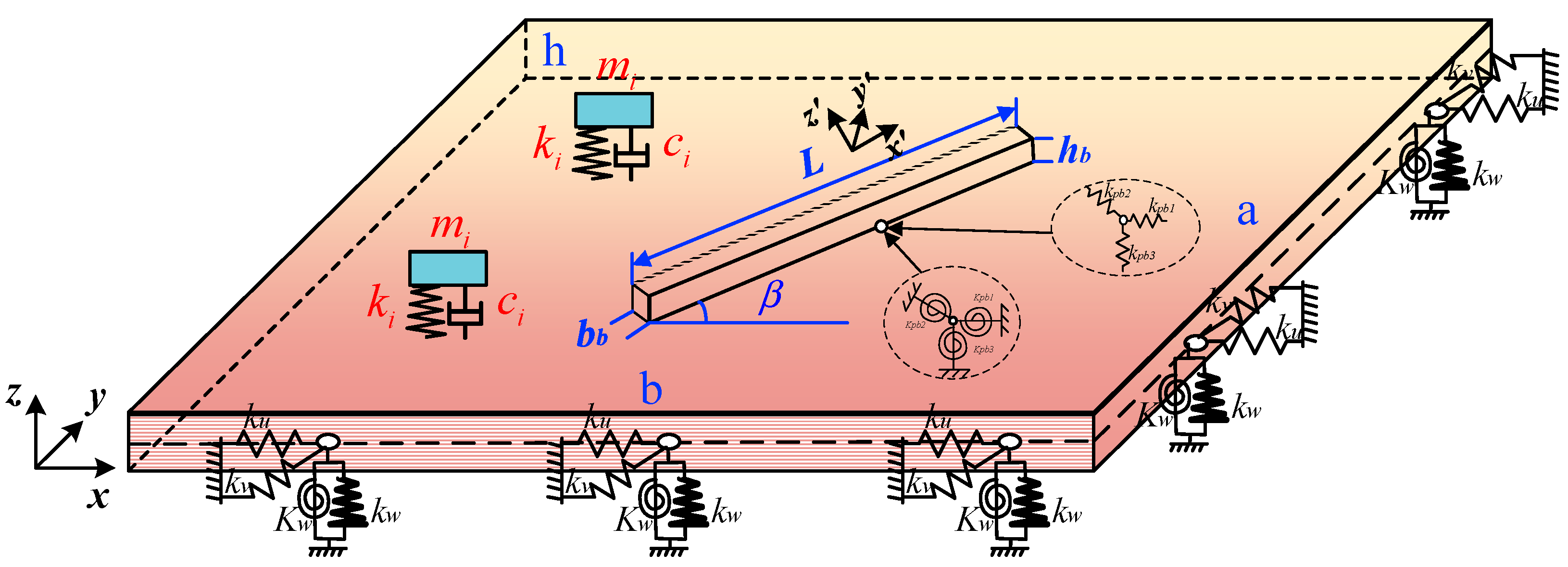
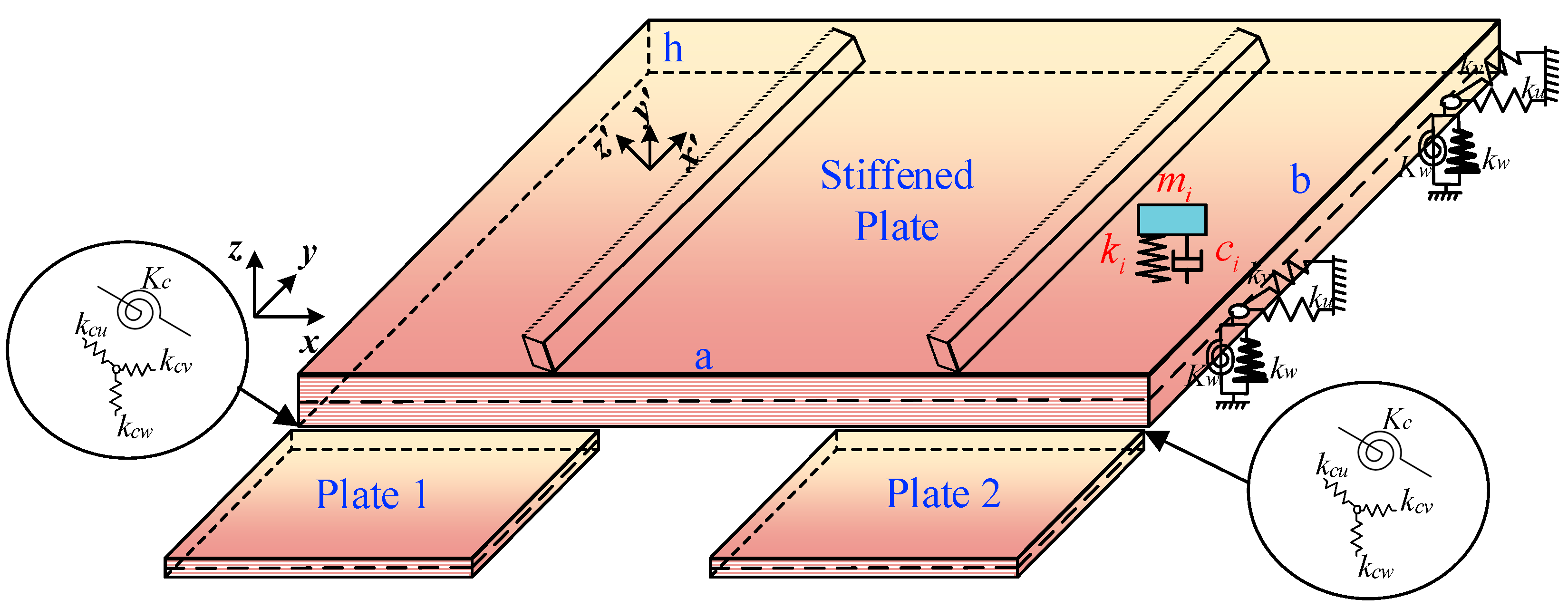
2.1. Establishment of Energy Formula

Firstly, a coupled dynamic vibration absorption model for stiffened plates has been introduced. By means of introducing artificial spring, the coordinate system and geometric symbol of the stiffened plate and dynamic vibration absorber are displayed in Figure 1. The stiffened plate’s length, width, and thickness, respectively, correspond to a, b, and h. Similarly, the width, length, and thickness of the stiffened rib are, respectively, bb, L, and hb. The angle between the stiffened rib and the local coordinates of the plate is β . The main and regional coordinates of the plate and stiffened rib are, respectively, (xyz) and (x’y’z’). To simulate arbitrary boundary conditions, artificial springs ku, kv, kw, and Kw are placed on each side of the stiffened plate. The DVA is simplified as parameters composed of weight ( m i ), spring ( k i ), and damper ( c i ). The coordinates of the installation site of the DVA are denoted as ( x i , y i ) . The relationship between the rib and plate is characterized by linear springs (kpb1, kpb2, kpb3) and rotary restraint springs (Kpb1, Kpb2, Kpb3).
Furthermore, more sub-plates have also been introduced on the basis of the stiffened plate in Figure 1. To simulate the connection relationship between the newly introduced plate subsystems and the stiffened plate, coupling springs kcu, kcv, kcw, and Kc are introduced. Finally, the sketch map of the coupled plate structures composed of stiffened plates and sub-plates is displayed in Figure 2.
The elastic strain energy of the irregular stiffened plate equipped with DVA can be expressed as follows:
V = i = 1 N p V p + i = 1 Q V b + V c p b + i = 1 R V d = i = 1 N p D P 2 S 2 w x 2 2 + 2 w y 2 2 + 2 μ P 2 w x 2 2 w y 2 + 2 1 μ p 2 w x y 2 d S + G p 2 S u x + v y 2 2 1 μ p u x v y + 1 μ p 2 v x + u y 2 + i = 1 Q 1 2 0 L D b z 2 w b z x 2 2 + D b y 2 w b y x 2 2 + E b A b u b x 2 + G b J b θ b x 2 d x 1 2 0 L i k p b 1 w w b z 2 + k p b 2 v cos β u sin β w b y 2 + k p b 3 v sin β + u cos β u b 2 d x + 1 2 0 L K p b 1 w x p b w b z x 2 + K p b 2 1 2 v x u y w b y x 2 + K p b 3 w y p b θ b 2 d x + 1 2 i = 1 R k r z r w r ( x i , y i ) 2
In Equation (1), Np signifies the number of plate structures, Q corresponds to the number of stiffened ribs, R signifies the number of DVA, Vp corresponds to the strain energy of the plate structure, Vb signifies the strain energy of the stiffened ribs, and V C p b stands for the static energy of spring between ribs and stiffened plate. V d signifies the strain energy of the spring between the DVA and the stiffened plate. The stiffened plate’s bending stiffness and extensional rigidity are represented by Dp and Gp, respectively. Db, Eb, and Gb, respectively, correspond to the bending stiffness, elastic modulus, and shear modulus of the rib structure. Ab and Jb, respectively, represent the cross-sectional area and torsional stiffness of the rib structure. z r and w r ( x 0 , y 0 ) , respectively, represent the displacement of the DVA and location point ( x 0 , y 0 ) . In addition, the kinetic energy of the stiffened plate equipped with DVA can be written as follows [44]:
T = i N P T p + i Q T b + i R T d = i N P ρ p h 2 S u t 2 + v t 2 + w t 2 d S + i Q ρ b ω 2 2 0 L i A b w b z 2 + A b w b y 2 + A b u b 2 + J b θ b 2 d x + i R 1 2 m r z ˙ r 2
In Equation (2), ρ p and ρ b respectively correspond to the density of the plate and rib structure. Td signifies the kinetic energy of the DVA. The following is an expression for the energy of edge constraints of the plate structure [45]:
V i s = 1 2 0 a k y 0 w ( x , y , t ) 2 + K y 0 w ( x , y , t ) y 2 + k u y 0 u ( x , y , t ) 2 + k v y 0 v ( x , y , t ) 2 y = 0 d x + 1 2 0 a k y b w ( x , y , t ) 2 + K y b w ( x , y , t ) y 2 + k u y b u ( x , y , t ) 2 + k v y b v ( x , y , t ) 2 y = b d x + 1 2 0 b k x 0 w ( x , y , t ) 2 + K x 0 w ( x , y , t ) x 2 + k u x 0 u ( x , y , t ) 2 + k v x 0 v ( x , y , t ) 2 x = 0 d y + 1 2 0 b k x a w ( x , y , t ) 2 + K x a w ( x , y , t ) x 2 + k u x a u ( x , y , t ) 2 + k v x a v ( x , y , t ) 2 x = a d y
k and K, respectively, correspond to the rigidity value of linear and rotational springs on different edges of each plate.
The elastic potential energy stored in the coupling spring between different plate structures is expressed as follows:
V ij C = 1 2 0 a i k cw w i w j 2 + k cu u i u j 2 + k cv v i v j 2 + K c w i / x i w j / x j 2 d x i
When the Rayleigh damping is introduced as follows:
C = α 0 M + β 0 K
The total consumption energy of the coupling system can be expressed in the following form:
W D = 0 a 0 b c w ( x , y , t ) / t w ( x , y ) d x d y + i = 1 r c r z ˙ r w ˙ r ( x 0 , y 0 ) z r w r ( x 0 , y 0 )
In the equation above, c and cr, respectively, denote the damping of the coupled plate structures and DVA.
The work performed by the external concentrated load can be written as follows:
W e = 0 a 0 b F δ x x e δ y y e w x , y d x d y
The Lagrange energy function of the stiffened plate and DVA systems can be written as below:
L = V + V s + V i j c T W D W e
To overcome the discontinuity of the displacement allowance function, the improved Fourier series method proposed in [46] is utilized. In addition, the displacement function of DVA is written as follows:
z x , y , t = E ( x 0 , y 0 ) e i w t
where E ( x 0 , y 0 ) is the coefficient of displacement function for the dynamic vibration absorber. Based on the Rayleigh–Ritz method, partial derivatives of Fourier coefficients ζ are expressed as follows:
L ζ = 0 ζ = A m n , B m n , C m n , D m n , E x 0 , y 0
Redescribing Equation (10) using the matrix form, the simplification is expressed as follows:
M x ¨ + C x ˙ + K x = F
The symbols M , C , and K stand for the mass, damping, and stiffness matrix, respectively. x is the displacement component of the coupled system composed of the coupled plate structures and the DVA. F represents the vector of external force. Above all, the mathematical model of the coupled plate structures with DVA is established.

2.2. Design of Parameters of DVA of Coupled Plate Structures

When the coupled plate structure is regarded as a continuum system, the first step to determining the parameters of DVA is solving the equivalent mass of the controlled mode. On the basis of the above mathematical model, the equivalent mass of the coupled plate structure can be derived according to the following formula [47]:
M i k = Δ m i k ω i k 2 Ω i 2 ω i k 2
where Δ m i k denotes the additional mass installed on the coupled plate structure, Ω i represents the i-order natural frequency of the coupled plate structure, and ω i k is the i-order natural frequency of the system consisting of a coupled plate structure and given mass.
Taking the stiffened plate as an example, the side length of the square stiffened plate is 6m, and the thickness of the stiffened plate is 0.03 m. The width and height of the rib located in the middle of the stiffened plates are, respectively, bb = 0.04 m and hb = 0.15 m.
The equivalent mass corresponds to the first three modes using the current method, and the FEM (S4R model, 10,100 elements) is listed in Table 1.
According to Table 1, the efficiency of solving equivalent mass has been greatly improved using the current method. By means of changing the additional mass and curve fitting, the equivalent mass can be easily derived through the current mathematical model. There is no need for finite element meshing and repeated calculations; the solution time of equivalent mass is greatly reduced in comparison with FEM.
The mass ratio μ can be rapidly determined based on the equivalent mass. Meanwhile, the frequency and damping of the DVA can be determined quickly according to the optimal homology principle
γ = ω n / Ω i = 1 / 1 + μ
ζ opt   = 3 μ 8 ( 1 + μ ) 3
where ω n is the frequency of the DVA, and ζ opt   is the optimal damping. Altogether, the design method of the DVA of the coupled plate structure is illustrated in Figure 3.
Firstly, the mathematical model of the coupled plate structure can be established quickly according to the research mentioned above. When the model changes, only the parameters need to be modified without repeated modeling and meshing. Secondly, the boundary spring stiffness is adjusted to achieve the equivalency of the real boundary condition. Finally, the equivalent mass and DVA parameters can be, respectively, determined quickly according to the current mathematical model and optimal coherent design method [48] presented in Equations (13) and (14).

3. Experiment Verification

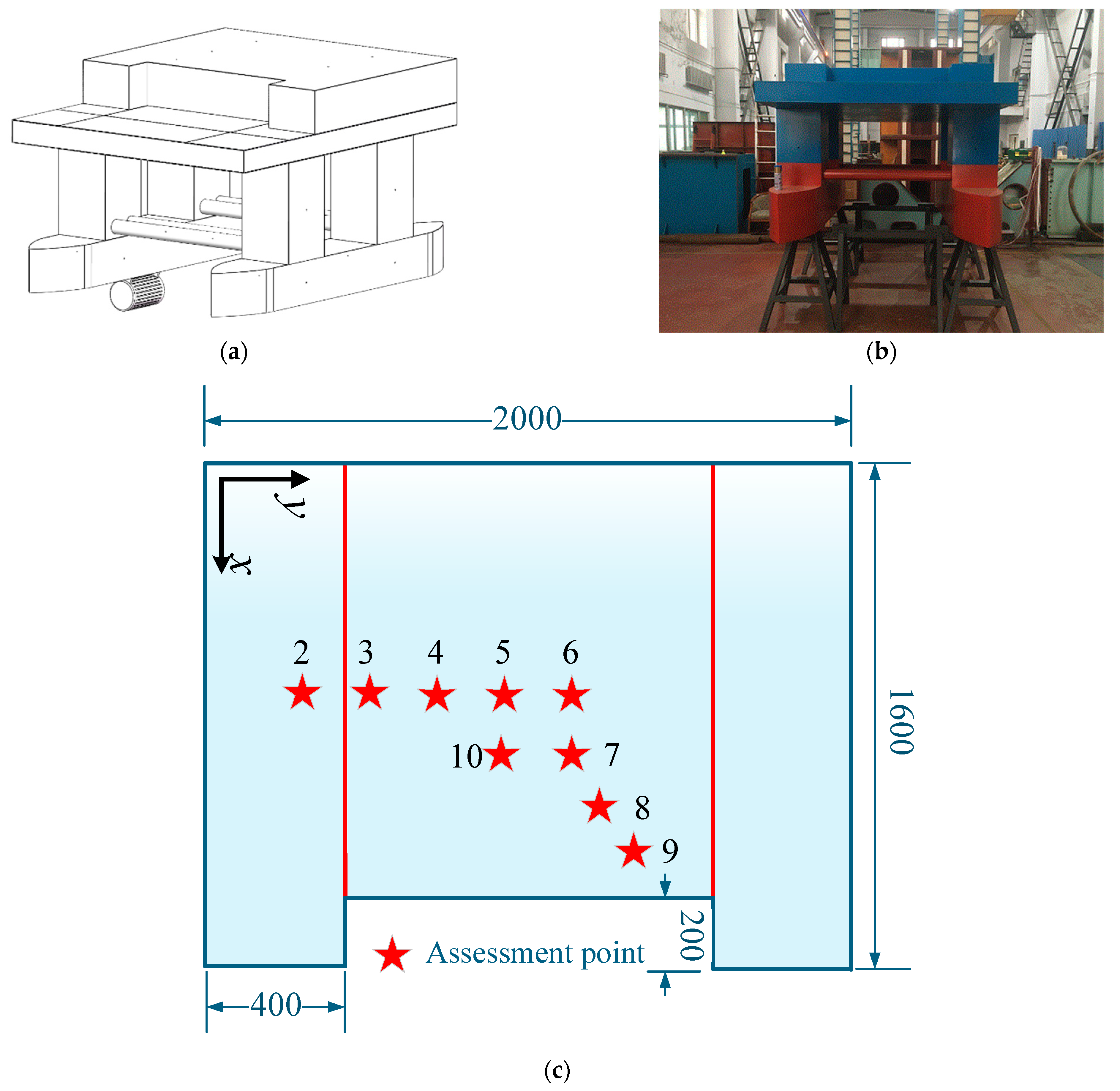
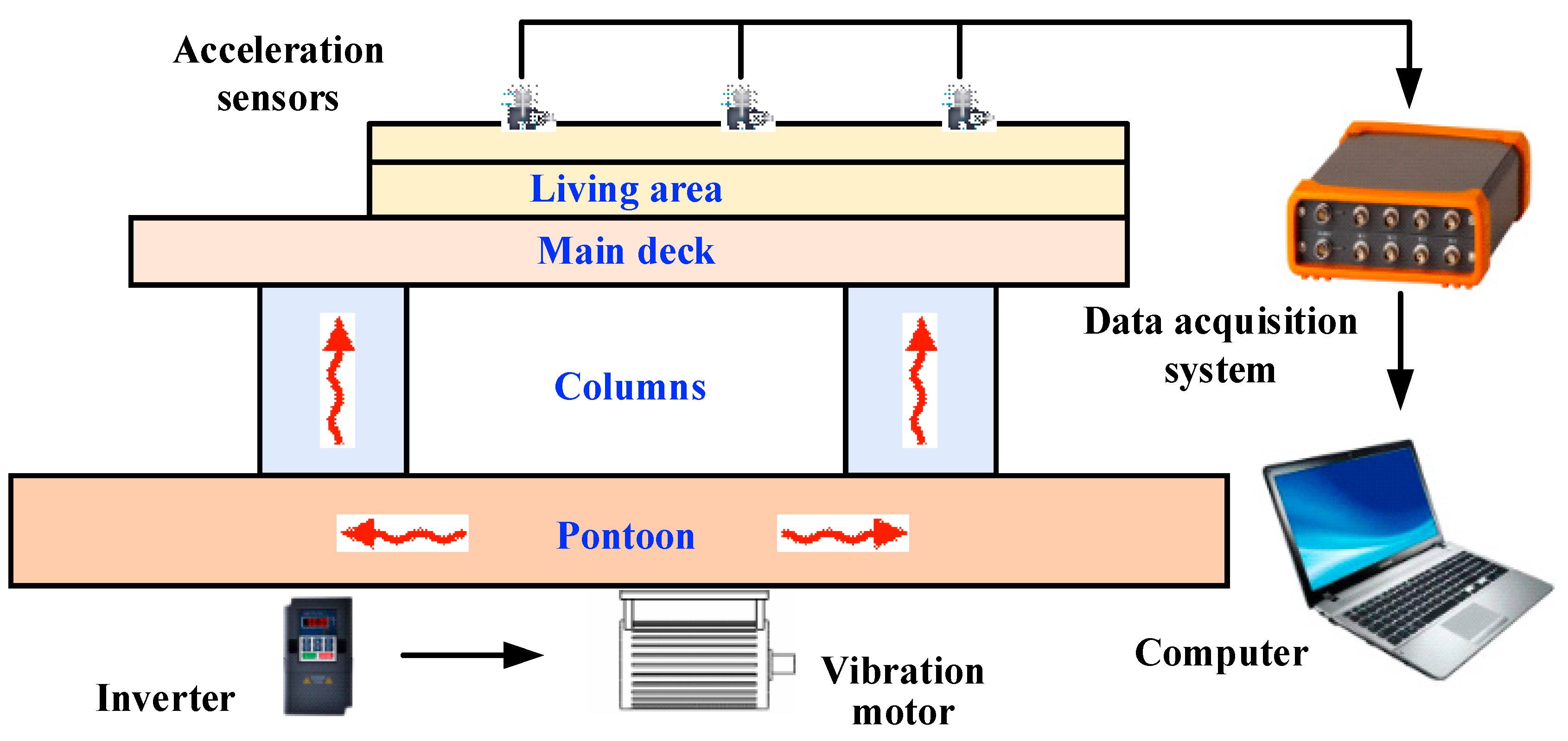
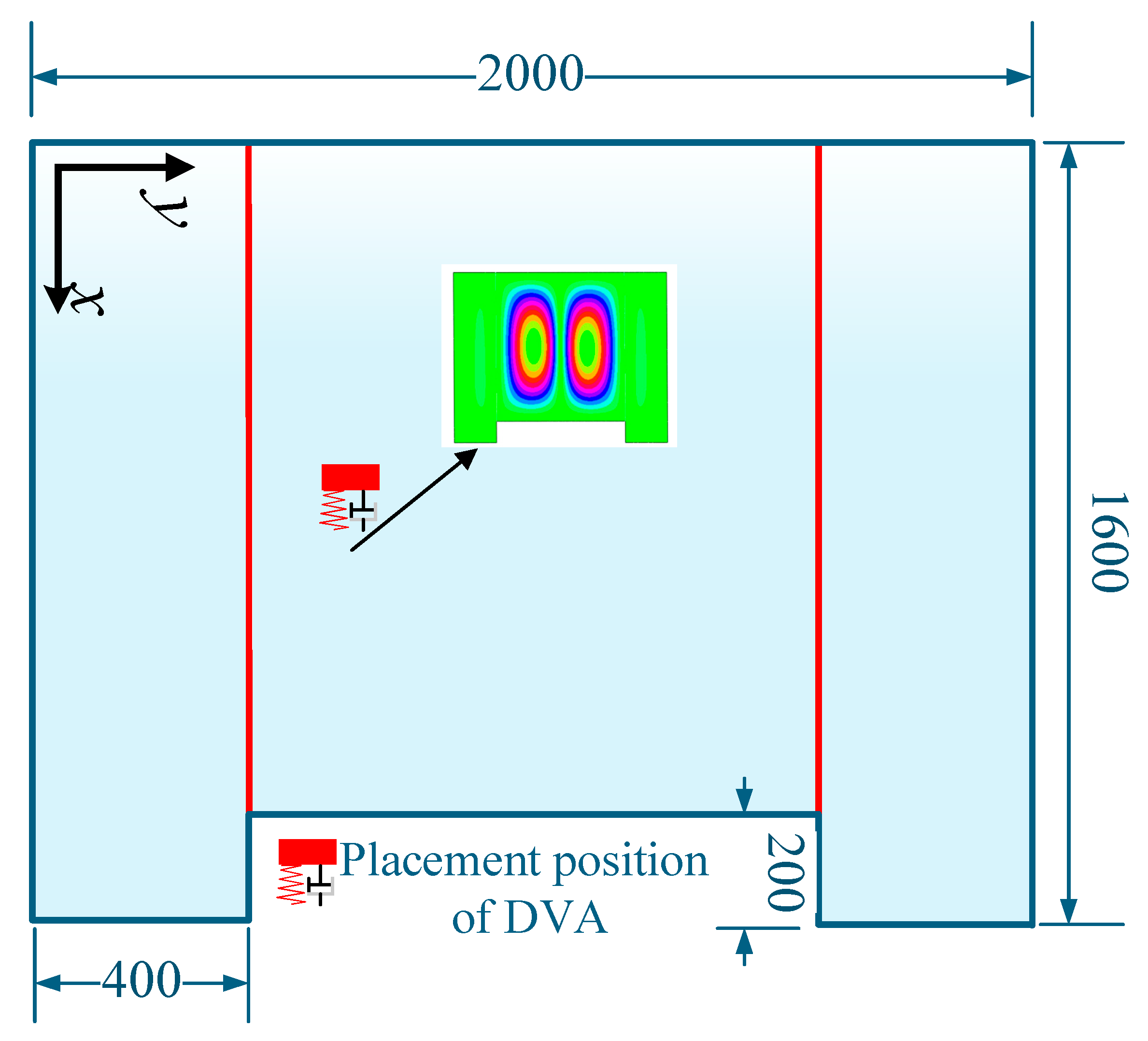
3.1. The Description of the Experiment Model

To further verify the effectiveness of the method presented in the previous section, an experiment of the coupled plate structure has been conducted. The upper deck of a scaled semi-submersible platform model presented in Figure 4a,b is chosen as the research object. The coupled plate system is composed of a stiffened plate and two plate sub-systems. As displayed in Figure 4c, the upper deck is dimensioned at 2000 mm × 1600 mm, while the plate thickness is 2 mm. The dimension of the T-shaped ribs set at 0.4 m and 1.6 m of the long side of the upper deck is 100 × 8 100 × 5.5 mm.
The experiment was composed of a modal test and a vibration response test. During the vibration response test, the vibration accelerometers were placed according to Figure 4c. The force hammer and vibration motor were, respectively, chosen as excitation sources in the modal test and vibration response test. The instruments utilized during the experiment comprised acceleration sensors, force transducers, power amplifiers, and a data acquisition system. Table 2 displays the particular models and specifications of the devices.
Above all, the upper deck of the scaled model was chosen as the research object in the current research. During the test, the data captured by acceleration sensors installed on the upper deck were transmitted to a signal processor within the data acquisition system and subsequently analyzed on a computer. The experimental setup is presented in Figure 5.

3.2. Design of DVA of the Coupled Plate Structure

When the vibration motor displayed in Figure 5 works in the range between 20–30 Hz, it can be adjusted by an inverter. The vibration response curves of typical assessment points in Figure 4c are shown in Figure 6.
As displayed in Figure 6, the greatest peak appears at 25.6 Hz of the vibration response curves of different assessment points. Test points 3 and 4 are symmetrical at about the third-order mode wave belly of the upper deck. As a result, the vibration acceleration levels of test points 3 and 4 at the frequency of 25.6Hz are almost the same. However, test point 3 is closer to the vibration motor, and the vibration response is also greater under other frequencies. It can be seen from Figure 6c that test point 7 is closer to the wave peak of the third-order mode (25.6Hz), and the response of test point 7 is significantly greater than that of test point 8 at this frequency. However, the response of test point 7 is smaller than that of test point 8 under other frequencies. It is further shown that the vibration response of the test point is closely related to the distance between the test point and the wave belly of the corresponding mode.
To gain a better understanding of the vibration of the upper deck, both the modal test and a numerical simulation were conducted.
By means of PolyLSCF (least squares complex frequency domain method with multiple reference points), the modal test data were analyzed. The comparison of the mode and frequency of the upper deck between modal test and current method is displayed in Figure 7.
When the stiffness values of linear and rotational springs are, respectively, set to 1010 (N/m) and 105 (N·m/rad), the modal shapes and natural frequencies measured by the test are in good agreement with the numerical model proposed in the current research. The validity of the proposed equivalent mathematical model in Section 2.1 is verified [49].
Despite the favorable experimental results observed in this study, which can reflect objective facts, certain errors in the experiment are inevitable. The sources of these errors primarily include two aspects: firstly, the inevitable processing errors during the cutting and welding of steel plates during the construction of the model, and secondly, errors caused by equipment and environmental interference during the experiment. Although the experimenters made every effort to properly ground the equipment to avoid interference from alternating current, some degree of error persists.
It is easy to find that the greatest peak appears at 25.6 Hz, corresponding to the second-order mode of the upper deck when the line spectrum vibration of the upper deck at 25.6 Hz is selected as the control object. As illustrated in Figure 3, the optimal installation point for the absorber is the antinode of the corresponding modal shape.
To determine the parameters of the dynamic vibration absorber of the upper deck, the first key point is the solution of the equivalent mass of the upper deck. Based on the equivalent numerical model and Equation (11) presented in the current research, the equivalent mass corresponding to 25.6 Hz is derived as 4.99 kg. The comparison between the current method and FEM (S4R model, 15,000 elements) is displayed in Table 3, and the computational time of the equivalent mass is reduced.
As mentioned above, the dynamic vibration absorber installation point of the experiment model is determined in Figure 8.
As displayed in Table 3, the equivalent mass corresponding to the third mode of the upper deck is 4.99 kg. When the mass ratio is 0.1, the parameters of the dynamic vibration absorber are easily derived through the optimal homology principle displayed in Equations (12) and (13). Table 4 lists the dynamic vibration absorber’s parameters corresponding to 25.6 Hz.
In order to better record the vibration of DVA, accelerometer 1 was installed on the DVA system. The comparison of vibration response between the dynamic vibration absorber (point 1) and upper deck (points 2 and 3) are displayed in Figure 9.
As shown in Figure 9, the DVA vibrates substantially more than the main structure when the frequency ratio between the DVA and the target control frequency is optimal (0.95).
Moreover, the comparison of the vibration acceleration responses of each assessment point with and without DVA is shown in Figure 10.
Figure 10 shows that vibration at assessment points 2 to 5 around the control frequency of 25.6 Hz is significantly reduced when the frequency ratio is adjusted to 0.95. Although new peaks emerge near the target control frequency for each assessment point, these new peaks are significantly low and thus can be considered negligible. Furthermore, Figure 10 shows that the absorption impact decreases as the distance between the assessment site and the DVA installation position rises. The vibration acceleration levels of each assessment point at the control frequency of 25.6 Hz are shown in Table 5.
The vibration response of each assessment point decreases when the frequency ratio is set to 0.95, as shown by the data in Table 4. Furthermore, the DVA’s effect diminishes as the distance grows between the assessment point and the associated wave belly. By averaging the energy of vibration data at each point, we found that the vibration acceleration of the upper deck is reduced by 18.9 dB at a frequency of 25.6 Hz.
The introduction of the DVA induces new peaks in the frequency response curves near the target control frequency; however, these new peaks are of a minimal amplitude and can be considered negligible. Moreover, the effectiveness of vibration absorption diminishes with increasing distance between the assessment points and the location of the DVA.

4. Conclusions

The line spectrum vibration control strategy of the partial resonance area of an ocean platform is studied in the current paper. The partial resonance area’s mathematical model with DVA serves as the foundation for a significantly increased equivalent mass solution efficiency. In addition, dynamic vibration absorption parameters can be determined easily in accordance with the procedure presented in the research. Ultimately, an experiment conducted on a scaled model of an offshore platform verifies the validity of the proposed model and procedure. The following is a summary of the primary findings presented in this paper:
(1)
A mathematical model of the partial resonance area was established. The experiment’s measurements of the modal shape and natural frequency accord well with the mathematical model’s computation findings, demonstrating the viability of the suggested mathematical model.
(2)
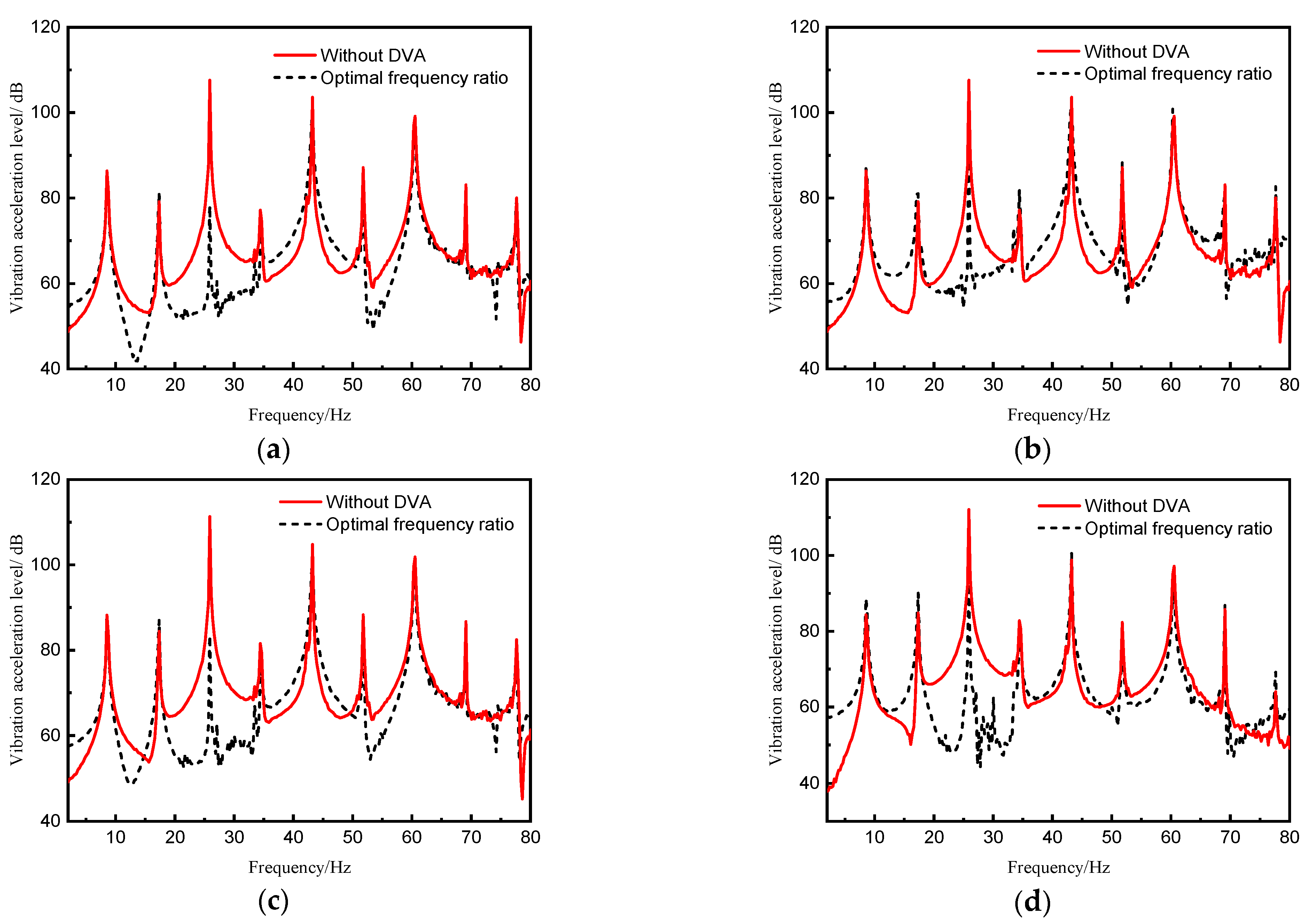
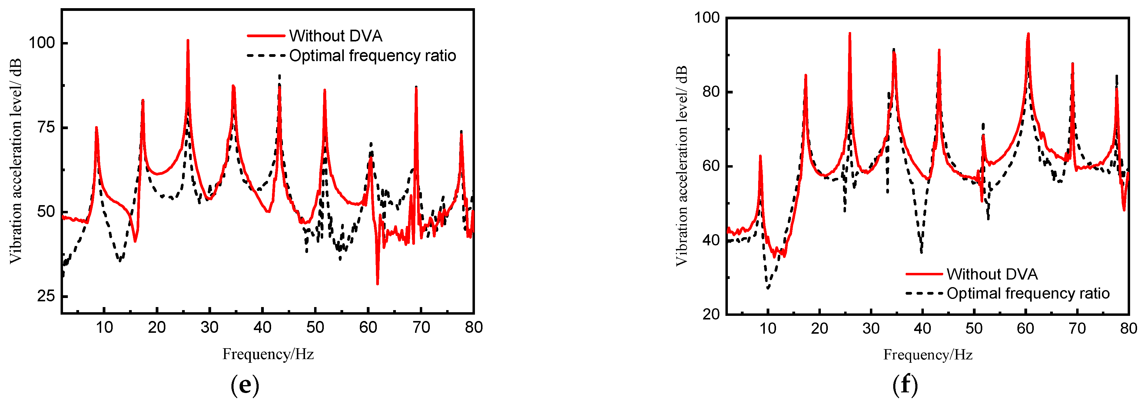
The validity of fast determination of parameters of DVA of partial resonance area is also verified by the experiment. When the frequency ratio is optimal, the vibration control effect of the line spectrum to be controlled is the best. New peaks emerge near the target control frequency for each assessment point, these new peaks are significantly low and thus can be considered negligible.
(3)
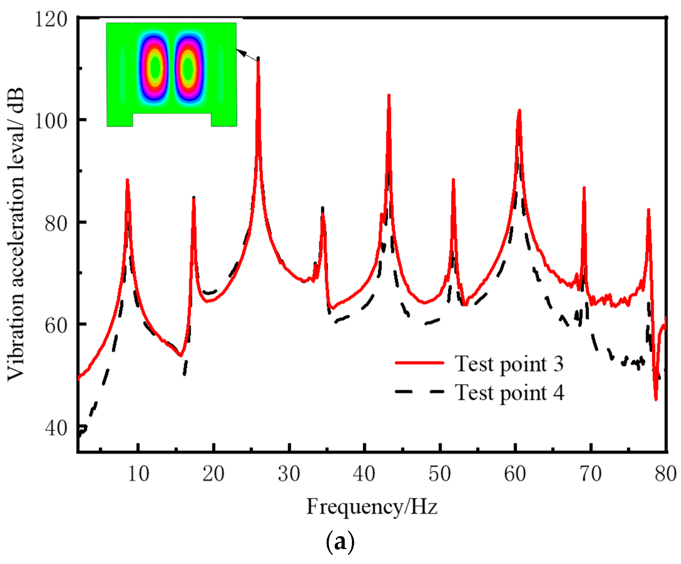
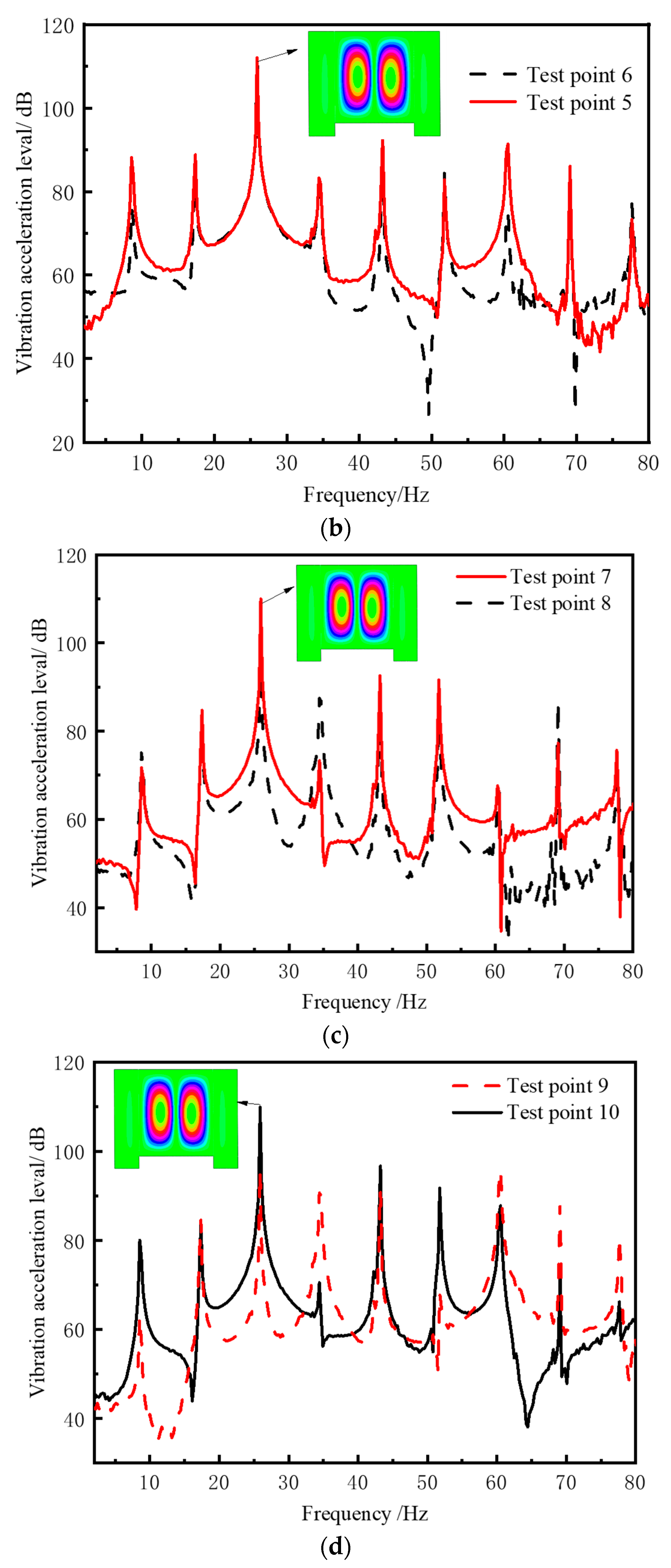
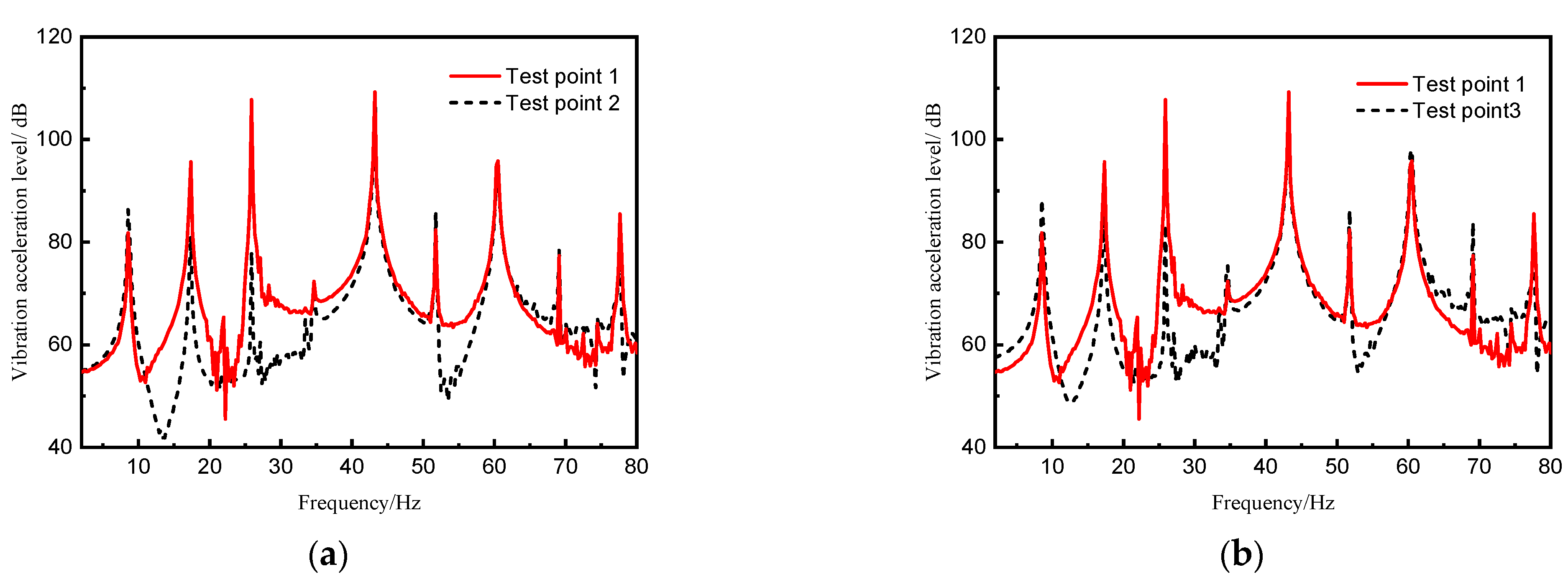
A typical assessment point response under excitation load reveals the magnitude of the response of the checkpoint at the line spectrum frequency is closely related to the distance between the checkpoint and the corresponding mode wave belly.
(4)
As the distance between the assessment points and the DVA location increases, the effectiveness of vibration absorption decreases.
(5)
The method proposed in this study will be used to design and study new types of dynamic vibration-absorbing equipment in the future, and with the application of composite materials in marine equipment gradually, this method can also be extended to realize spectrum vibration control of composite materials.

Author Contributions

Y.D.: Writing-original draft; F.J.: Software; Y.T.: Validation; J.Z.: Writing, review and editing; Y.Z.: Investigation; Y.M.: Supervision. All authors have read and agreed to the published version of the manuscript.

Funding

This study was funded by National Natural Science Foundation of China (52201361).

Institutional Review Board Statement

Not applicable

Informed Consent Statement

Not applicable.

Data Availability Statement

The authors confirm that the data supporting the findings of this study are available within the article.

Conflicts of Interest

The authors declare no conflict of interest.

References

  1. Asiri, S.A.; AL-Zahrani, Y.Z. Theoretical analysis of mechanical vibration for offshore platform structures. World J. Mech. 2014, 4, 1–11. [Google Scholar] [CrossRef]
  2. Zhang, B.-L.; Han, Q.-L.; Zhang, X.-M. Recent advances in vibration control of offshore platforms. Nonlinear Dyn. 2017, 89, 755–771. [Google Scholar] [CrossRef]
  3. Liu, Y.; Lu, Z.; Yan, X.; Liu, Z.; Tang, L. Measurement and modelling of the vibration induced by working equipment on an offshore platform. Ocean Eng. 2021, 219, 108354. [Google Scholar] [CrossRef]
  4. Zhang, P.; Wu, Z.H.; Cui, C.Y.; Yao, R.Q. Mitigation of Ice-Induced Vibration of Offshore Platform Based on Gated Recurrent Neural Network. J. Mar. Sci. Eng. 2022, 10, 967. [Google Scholar] [CrossRef]
  5. Qin, Y.; Pang, F.; Tang, Y.; Lin, Y.; Zhang, H.; Li, H. Vibration isolation characteristics of a novel composite flexible vibration-damping foundation. J. Vib. Control 2024. [Google Scholar] [CrossRef]
  6. Zhang, K.; Pan, J.; Lin, T.R. Vibration of rectangular plates stiffened by orthogonal beams. J. Sound. Vib. 2021, 513, 116424. [Google Scholar] [CrossRef]
  7. Yan, C.; Vescovini, R.; Jansen, E.L. A semi-analytical framework for nonlinear vibration analysis of variable stiffness plates. Compos. Struct. 2021, 269, 113954. [Google Scholar] [CrossRef]
  8. Brubak, L.; Hellesland, J.; Hareide, O.J. Vibration analysis of plates with arbitrary stiffener arrangements using a semi-analytical approach. In Proceedings of the MARINE V: V International Conference on Computational Methods in Marine Engineering, Hamburg, Germany, 29–31 May, 2013. [Google Scholar]
  9. Castro, S.G.; Donadon, M.V. Assembly of semi-analytical models to address linear buckling and vibration of stiffened composite panels with debonding defect. Compos. Struct. 2017, 160, 232–247. [Google Scholar] [CrossRef]
  10. Shen, Y.J.; He, X.C.; Chen, W.; Liang, N.; Peng, L.X. Meshless simulation and experimental study on forced vibration of rectangular stiffened plate. J. Sound. Vib. 2022, 518, 116602. [Google Scholar] [CrossRef]
  11. Gao, C.; Pang, F.Z.; Li, H.C.; Jia, D. A semi-analytical method for the dynamic characteristics of stiffened plate with general boundary conditions. Thin-Walled Struct. 2022, 178, 109513. [Google Scholar] [CrossRef]
  12. Sahoo, P.R.; Barik, M. Free Vibration Analysis of Stiffened Plates. J. Vib. Eng. Technol. 2020, 8, 869–882. [Google Scholar] [CrossRef]
  13. Li, Y.G.; Zhou, Q.W.; Zhou, L.; Zhu, L.; Guo, K.L. Flexural wave band gaps and vibration attenuation characteristics in periodic bi-directionally orthogonal stiffened plates. Ocean Eng. 2019, 178, 95–103. [Google Scholar] [CrossRef]
  14. Wang, Q.; Xie, F.; Qin, B.; Zhong, R.; Yu, H. Dynamics and power flow control of irregular elastic coupled plate systems: Precise modeling and experimental validation. Int. J. Mech. Sci. 2020, 185, 105760. [Google Scholar] [CrossRef]
  15. Feng, G.; Zhu, G.; Liu, X. Plates’ parameters influence on the power transmission in an L-shaped plate system. In Proceedings of the International Conference on Mechatronics and Control (ICMC), Jinzhou, China, 3–5 July 2014. [Google Scholar]
  16. Zhao, Y.; Guo, F.; Xu, D. Modeling and flexural vibration analysis of a double-thin-plate coupling system connected by nonlinear elements. Nonlinear Dyn. 2024, 112, 11851–11867. [Google Scholar] [CrossRef]
  17. Mahapatra, K.; Panigrahi, S.K. Effect of general coupling conditions on the vibration and power flow characteristics of a two-plate built-up plate structure. Mech. Based Des. Struct. Mach. 2021, 49, 841–861. [Google Scholar] [CrossRef]
  18. Li, Q.H.; Sanchez, J.; Benaroya, H.; Wang, J.F.; Xue, K. Free Vibration Analysis of Moderately Thick Coupled Plates with Elastic Boundary Conditions and Point Supports. Int. J. Struct. Stab. Dyn. 2019, 19, 1950150. [Google Scholar] [CrossRef]
  19. Hamedani, S.J.; Khedmati, M.R.; Azkat, S. Vibration analysis of stiffened plates using finite element method. Lat. Am. J. Solids Struct. 2012, 9, 1–20. [Google Scholar] [CrossRef]
  20. Ma, Y.; Zhang, Y.; Kennedy, D. Energy flow analysis of mid-frequency vibration of coupled plate structures with a hybrid analytical wave and finite element model. Compos. Struct. 2016, 175, 1–14. [Google Scholar] [CrossRef]
  21. Ma, Y.; Zhang, Y.; Wang, B.P. A hybrid analytical and finite element method for mid-frequency vibration analysis of plate structures with discontinuities. Int. J. Struct. Stab. Dyn. 2017, 17, 1750052. [Google Scholar] [CrossRef]
  22. Shi, P.; Kapania, R.K.; Dong, C.Y. Vibration and buckling analysis of curvilinearly stiffened plates using finite element method. AIAA J. 2015, 53, 1319–1335. [Google Scholar] [CrossRef]
  23. Som, A.; Das, D. Seismic vibration control of offshore jacket platforms using decentralized sliding mode algorithm. Ocean Eng. 2018, 152, 377–390. [Google Scholar] [CrossRef]
  24. Hemmati, A.; Oterkus, E. Semi-Active Structural Control of Offshore Wind Turbines Considering Damage Development. J. Mar. Sci. Eng. 2018, 6, 102. [Google Scholar] [CrossRef]
  25. Kandasamy, R.; Cui, F.; Townsend, N.; Foo, C.C.; Guo, J.; Shenoi, A.; Xiong, Y. A review of vibration control methods for marine offshore structures. Ocean Eng. 2016, 127, 279–297. [Google Scholar] [CrossRef]
  26. Zhang, B.-L.; Han, Q.-L.; Zhang, X.-M.; Tang, G.-Y. Active Control of Offshore Steel Jacket Platforms; Springer: Berlin/Heidelberg, Germany, 2019. [Google Scholar]
  27. Yuan, S.; Sun, Y.; Zhao, J.; Meng, K.; Wang, M.; Pu, H.; Peng, Y.; Luo, J.; Xie, S. A tunable quasi-zero stiffness isolator based on a linear electromagnetic spring. J. Sound Vib. 2020, 482, 115449. [Google Scholar] [CrossRef]
  28. Enferadi, M.H.; Ghasemi, M.R.; Shabakhty, N. Wave-induced vibration control of offshore jacket platforms through SMA dampers. Appl. Ocean. Res. 2019, 90, 101848. [Google Scholar] [CrossRef]
  29. Ghassempour, M.; Failla, G.; Arena, F. Vibration mitigation in offshore wind turbines via tuned mass damper. Eng. Struct. 2019, 183, 610–636. [Google Scholar] [CrossRef]
  30. Xu, Z.-D.; Xu, F.-H.; Chen, X. Vibration suppression on a platform by using vibration isolation and mitigation devices. Nonlinear Dyn. 2016, 83, 1341–1353. [Google Scholar] [CrossRef]
  31. Wang, S.; Yue, Q.; Zhang, D. Ice-induced non-structure vibration reduction of jacket platforms with isolation cone system. Ocean Eng. 2013, 70, 118–123. [Google Scholar] [CrossRef]
  32. Leng, D.; Zhu, Z.; Xu, K.; Li, Y.; Liu, G. Vibration control of jacket offshore platform through magnetorheological elastomer (MRE) based isolation system. Appl. Ocean Res. 2021, 114, 102779. [Google Scholar] [CrossRef]
  33. Kampitsis, A.; Kapasakalis, K.; Via-Estrem, L. An integrated FEA-CFD simulation of offshore wind turbines with vibration control systems. Eng. Struct. 2022, 254, 113859. [Google Scholar] [CrossRef]
  34. Wang, S.; Zhang, D. Ice-Induced Vibration Reduction on a Mooring Dolphin Platform Using an Isolation Cone System. J. Cold Reg. Eng. 2023, 37, 05023002. [Google Scholar] [CrossRef]
  35. Golafshani, A.A.; Gholizad, A. Friction damper for vibration control in offshore steel jacket platforms. J. Constr. Steel Res. 2009, 65, 180–187. [Google Scholar] [CrossRef]
  36. Patil, K.; Jangid, R. Passive control of offshore jacket platforms. Ocean Eng. 2005, 32, 1933–1949. [Google Scholar] [CrossRef]
  37. Minh Le, L.; Van Nguyen, D.; Chang, S.; Kim, D.; Cho, S.G.; Nguyen, D.D. Vibration control of jacket offshore wind turbine subjected to earthquake excitations by using friction damper. J. Struct. Integr. Maint. 2019, 4, 1–5. [Google Scholar] [CrossRef]
  38. Ou, J.; Long, X.; Li, Q.; Xiao, Y. Vibration control of steel jacket offshore platform structures with damping isolation systems. Eng. Struct. 2007, 29, 1525–1538. [Google Scholar] [CrossRef]
  39. Chen, D.; Huang, S.; Huang, C.; Liu, R.; Ouyang, F. Passive control of jacket–type offshore wind turbine vibrations by single and multiple tuned mass dampers. Mar. Struct. 2021, 77, 102938. [Google Scholar] [CrossRef]
  40. Dinh, V.N.; Basu, B. Passive control of floating offshore wind turbine nacelle and spar vibrations by multiple tuned mass dampers. Struct. Control Health Monit. 2015, 22, 152–176. [Google Scholar] [CrossRef]
  41. Hu, Y.; Wang, J.; Chen, M.Z.; Li, Z.; Sun, Y. Load mitigation for a barge-type floating offshore wind turbine via inerter-based passive structural control. Eng. Struct. 2018, 177, 198–209. [Google Scholar] [CrossRef]
  42. Sun, C.; Jahangiri, V. Bi-directional vibration control of offshore wind turbines using a 3D pendulum tuned mass damper. Mech. Syst. Signal Process. 2018, 105, 338–360. [Google Scholar] [CrossRef]
  43. Ghasemi, M.R.; Shabakhty, N.; Enferadi, M.H. Vibration control of offshore jacket platforms through shape memory alloy pounding tuned mass damper (SMA-PTMD). Ocean Eng. 2019, 191, 106348. [Google Scholar] [CrossRef]
  44. Du, J.; Li, W.L.; Jin, G.; Yang, T.; Liu, Z. An analytical method for the in-plane vibration analysis of rectangular plates with elastically restrained edges. J. Sound. Vib. 2007, 306, 908–927. [Google Scholar] [CrossRef]
  45. Zhao, J.; Wang, Q.; Deng, X.; Choe, K.; Zhong, R.; Shuai, C. Free vibrations of functionally graded porous rectangular plate with uniform elastic boundary conditions. Compos. Part B Eng. 2019, 168, 106–120. [Google Scholar] [CrossRef]
  46. Du, Y.; Zou, T.; Pang, F.; Hu, C.; Ma, Y.; Li, H. Design method for distributed dynamic vibration absorbers of stiffened plate under different boundary constraints. Thin-Walled Struct. 2023, 185, 110494. [Google Scholar] [CrossRef]
  47. Du, Y.; Tang, Y.; Zou, Y.; Wang, Y.; Pang, F.; Jia, F.; Ma, Y.; Wang, S. The low frequency multi-linear spectrum vibration control study of cylindrical shell through a semi-analytical method. Thin-Walled Struct. 2023, 196, 111521. [Google Scholar] [CrossRef]
  48. Wei, J.; Liu, W.; Gao, P.X.; Ding, Y.J. An Analytical Dynamic Model for Vibration Suppression of a Multi-Span Continuous Bridge by Tuned Mass Dampers. J. Mar. Sci. Eng. 2023, 11, 1017. [Google Scholar] [CrossRef]
  49. Zhang, S.; Zhu, X.; Li, T.; Yin, C.; Li, Q.; Chen, R. A Unified Solution for Free Vibration Analysis of Beam-Plate-Shell Combined Structures with General Boundary Conditions. Int. J. Struct. Stab. Dyn. 2022, 22, 2250080. [Google Scholar] [CrossRef]
Figure 1. Principle picture of stiffened plate equipped with DVA.
Jmse 13 00283 g001
Figure 2. Sketch map of irregular stiffened plate equipped with DVA.
Jmse 13 00283 g002
Figure 3. Design method of DVA of the coupled plate structure.
Jmse 13 00283 g003
Figure 4. The coupled plate of the experiment model. (a) Isometric view of the scaled model. (b) Scaled model of semi-submersible platform. (c) The upper deck of the scaled model.
Jmse 13 00283 g004
Figure 5. Schematic diagram of experimental scheme and system.
Jmse 13 00283 g005
Figure 6. Vibration response curves of typical assessment points under the action of vibration motor. (a) Test points 3 to 4. (b) Test points 5 to 6. (c) Test points 7 to 8. (d) Test points 9 to 10.
Jmse 13 00283 g006aJmse 13 00283 g006b
Figure 7. The comparison diagram about modal shapes. (a) 11.32 Hz (experiment). (b) 11.43 Hz (numerical solution). (c) 25.60 Hz (experiment). (d) 24.72 Hz (numerical solution). (e) 33.51 Hz (experiment). (f) 33.95 Hz (numerical solution).
Jmse 13 00283 g007
Figure 8. Diagram of base of dynamic vibration absorber.
Jmse 13 00283 g008
Figure 9. Comparison of assessment point response (Frequency ratio is 0.95). (a) Assessment point 2. (b) Assessment point 3.
Jmse 13 00283 g009
Figure 10. Vibration control effect of typical assessment points when frequency ratio is 0.95. (a) Assessment point 2. (b) Assessment point 3. (c) Assessment point 4. (d) Assessment point 5. (e) Assessment point 8. (f) Assessment point 9.
Jmse 13 00283 g010aJmse 13 00283 g010b
Table 1. Comparison of equivalent mass solution time.
Solution MethodThe First-Order Equivalent Mass (kg)The Second-Order Equivalent Mass (kg)The Third-OrderEquivalent Mass (kg)Computational Time (s)
Current method1154.71624.21105.313
FEM (S4R,10,100)1155.41624.11105.145
Table 2. Equipment parameters.
NameNumberModelValue
Acceleration sensors11DH1A111ESensitivity: 100 mV/g
Force transducers1CL-YD-312 ASensitivity: 4 pC/N
Vibration motor1MVE500/3Speed: 3000 rpm
Inverter1SAKO/SK680Power: 2.2 kw
Data acquisition system1DH5929NSampling rate: 20 kHz
Table 3. Equivalent mass of upper deck corresponding to 25.6 Hz (kg).
Method of CalculationEquivalent Mass (kg)Computational Time (s)
Current method4.9921
FEM (S4R,15,000)4.95220
Table 4. Third-order dynamic absorption parameters.
Mode NumberMass RatioFrequency RatioMass (kg)Frequency of
DVA (Hz)
Third0.10.950.524.3
Table 5. Vibration acceleration level of different checkpoints at frequency 25.6 Hz (dB).
Assessment Point Number23456789
Without DVA107.6107.6111.3112.1112109.9100.895.8
Optimal frequency ratio (0.95)78.293.183.492.593.971.692.785.1
Disclaimer/Publisher’s Note: The statements, opinions and data contained in all publications are solely those of the individual author(s) and contributor(s) and not of MDPI and/or the editor(s). MDPI and/or the editor(s) disclaim responsibility for any injury to people or property resulting from any ideas, methods, instructions or products referred to in the content.

