Abstract
With the urgent demand for net-zero emissions, renewable energy is taking the lead and wind power is becoming increasingly important. Among the most promising sources, offshore wind energy located in deep water has gained significant attention. This review focuses on the experimental methods, simulation approaches, and wake characteristics of floating offshore wind turbines (FOWTs). The hydrodynamics and aerodynamics of FOWTs are not isolated and they interact with each other. Under the environmental load and mooring force, the floating platform has six degrees of freedom motions, which bring the changes in the relative wind speed to the turbine rotor, and furthermore, to the turbine aerodynamics. Then, the platform’s movements lead to a complex FOWT wake evolution, including wake recovery acceleration, velocity deficit fluctuations, wake deformation and wake meandering. In scale FOWT tests, it is challenging to simultaneously satisfy Reynolds number and Froude number similarity, resulting in gaps between scale model experiments and field measurements. Recently, progress has been made in scale model experiments; furthermore, a “Hardware in the loop” technique has been developed as an effective solution to the above contradiction. In numerical simulations, the coupling of hydrodynamics and aerodynamics is the concern and a typical numerical simulation of multi-body and multi-physical coupling is reviewed in this paper. Furthermore, recent advancements have been made in the analysis of wake characteristics, such as the application of instability theory and modal decomposition techniques in the study of FOWT wake evolution. These studies have revealed the formation of vortex rings and leapfrogging behavior in adjacent helical vortices, which deepens the understanding of the FOWT wake. Overall, this paper provides a comprehensive review of recent research on FOWT wake dynamics.
1. Introduction
With the rapid development of the economy and industry, the demand for energy consumption is growing, but the traditional energy system restricts the further development of society [1]. To achieve the ambitious target of net-zero, great efforts have been made in developing renewable energy.
Wind power plays an important role in the energy system transition, while the floating offshore wind turbine (FOWT) is the focus of future wind power [2]. First, the wind resources suitable for a FOWT are quite abundant. Take China for example: the onshore wind power of 100 m height is 3900 GW and the cumulative installed capacity of onshore wind power was 404.79 GW by 2023; the capacity of offshore wind power is relatively less than that of onshore wind power but is growing rapidly. The exploitable offshore wind power near the coast at a 100 m height is about 750 GW and that located in the deep water is more than 2200 GW; the cumulative installed capacity of offshore wind power was 36.55 GW by 2023. It is noted that the capacity of wind power of an FOWT is only 0.019 GW, which means the wind energy in deeper water has great potential. Furthermore, in terms of electricity consumption, onshore wind farms in China are mainly concentrated in the northern inland areas with a high wind speed, but the local electric power consumption capacity is insufficient and long-distance transmission is limited. Because the offshore wind power is close to the main electric power load in southeast China the offshore wind power has an obvious consumption advantage.
As shown in Table 1, in the world’s major wind markets, water depths greater than 60 m have more wind resources. All these facts indicate that the FOWT is the future of wind power.

Table 1.
The proportion and reserves of wind resources in deep water.
The concept of the floating wind turbine was originally proposed by Heronemus to make use of wind energy located in deep water. In the international standard of offshore wind energy development, deep water refers to the area with a depth of more than 60 m and far sea refers to the area more than 50 km away from the shore. In far and deep water, the cost of bottom-fixed wind turbines increases rapidly, while the floating offshore wind turbine (FOWT) is not limited by the water depth and the installation of wind turbines can be simplified; the technical and economic advantages make the FOWT more attractive. Table 2 shows some main floating wind power projects in 2023. Many countries have carried out development planning for FOWTs. Yet, the key technologies of floating wind power equipment have not been completely achieved and the standard system, especially the design standards and design methods and tools, has not been formed. Thus, further research on FOWTs is needed to promote the development of offshore wind power.
Table 2.
Part of the floating wind power projects in operation or under construction.
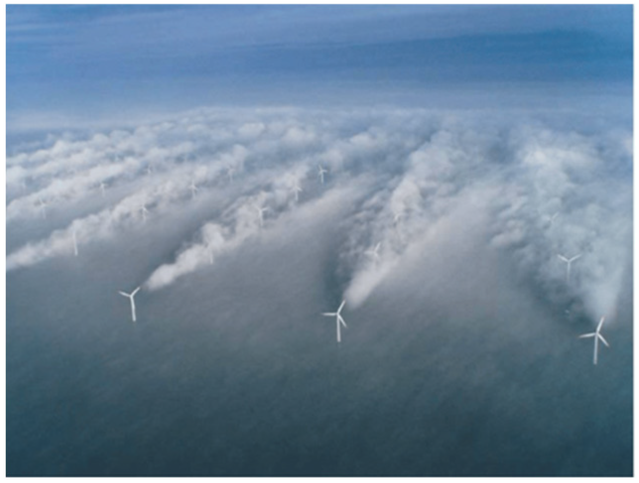
Wake effect (shown in Figure 1) is one of the greatest challenges in large-scale wind farms. The significant feature of wind energy is a low power density; the wind turbine extracts energy from the incoming wind, resulting in a velocity deficit and turbulence intensity increase. According to typical studies of the wake impact, the power loss in downstream wind turbines caused by velocity deficit is about 20% and the fatigue load increase in downstream wind turbines caused by turbulence intensity increase is about 10–45% [3,4,5]. For large-scale wind farms, it has been proven that the optimization of micro-sitting and turbines control strategies setting is an effective way to enhance the total power generation efficiency and reliability of accessing power systems, which requires an accurate evaluation of the power performance of wind farms under complex internal flows and interactions with varying atmospheres. Under the coupling action of wind, wave and ocean current, the FOWT has six degrees of freedom (DOF) motions (shown in Figure 2), which makes the turbulence structure evolution of the turbine wake more complex and brings challenges to the wake effect evaluations.
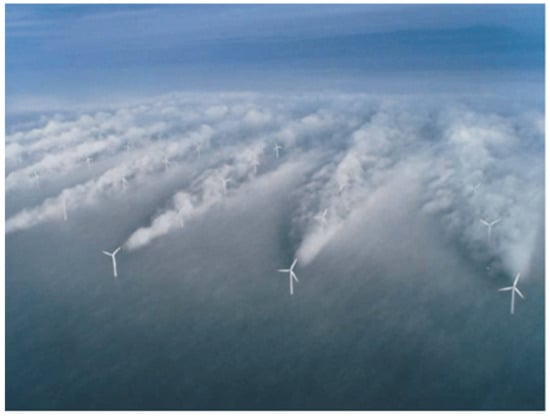
Figure 1.
Horns Rev wind farm in salt spray weather [6].
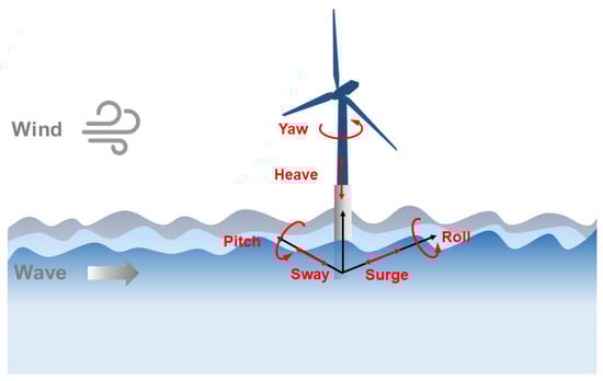
Figure 2.
6-DOF motions of a FOWT under the coupling of wind, wave and ocean current.
The FOWT is basically composed of a wind turbine, floating platform and mooring system. In the past two decades, some representative floating wind farm projects have started operating. In 2009, the first megawatt floating wind turbine, Hywind one, was built and installed in Norway by Siemens. In 2017, the first offshore floating wind farm, Hywind Scotland, was officially commissioned in Scotland; this wind farm contains five SGRE 6 MW wind turbines. The Kincardine wind farm, also in Scotland, has a total installed capacity of 50 MW, including five Vestas V164-9.5 MW wind turbines. In 2023, the largest floating offshore wind farm yet, Hywind Tampen Wind Farm, with 11 turbines and a total installed capacity of 88 MW, was put into operation off the west coast of Norway. All these facts indicate that floating offshore wind energy is gradually blooming and the further construction of floating wind farms is in urgent need of relevant technological progress.
Described in technical standard DNV GL-ST-0119, there are four typical FOWT platforms at present (shown in Figure 3): the Barge Platform (Barge), the Semi-Submersible Platform (Semi-Sub), the Spar Platform (Spar) and the Tension Leg Platform (TLP). According to the comprehensive review conducted by Edwards et al. [7], the evolution of FOWT platforms can be summarized in four stages: Phase I (1990–2010) is characterized by proof-of-concept studies and exploratory concepts. In Phase II (2005–2015), influenced by the oil and gas (O&G) industry, limited platform modifications were conducted on offshore oil and gas platforms. Thus, at that time, the floating platform did not fully meet the needs of floating wind turbines. In Phase III (2010–2020), specialized designs adapted to different ocean conditions began to emerge and the economic cost was greatly reduced. Finally, Phase IV (2015–present) is characterized by a number of alternative cost reduction strategies. Currently, most floating platform designs are Semi-Sub types, and most floating platforms are designed to install one wind turbine rather than multiple; furthermore, concrete floating platforms are becoming a new trend because the cost is lower [7].
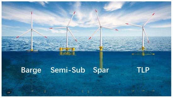
Figure 3.
Four typical FOWT platforms [8].
Relevant studies mainly focus on the aerodynamic performance, hydrodynamic response and structural load of FOWTs. The six-degree-of-freedom motion brings a change in the relative wind speed to the turbine blade as well as the interaction between the turbine blade and vortex, which lead to the dynamic aerodynamic performance of the wind turbine. In terms of hydrodynamics, FOWTs have similarities with other floating structures in offshore engineering, which means that the theory and model of ocean hydrodynamics are still applicable to FOWTs. However, most existing numerical simulation programs for hydrodynamics are founded on either linear wave theory and classical linear hydrodynamics, or the Morrison equation, or a combination and enhancement of these two approaches. It is noted that these three methods still have some shortcomings. One significant limitation is their inability to accurately address the large motion dynamics of floating platforms [9].
The current review papers mostly focus on the bottom-fixed wind turbine wake, while this paper focuses on the wake evolution and characteristics of FOWTs. In the paper, the experimental and numerical simulation progress of the floating wind turbine wake is comprehensively reviewed.
2. Fundamental Aerodynamics of Wind Turbine Wake
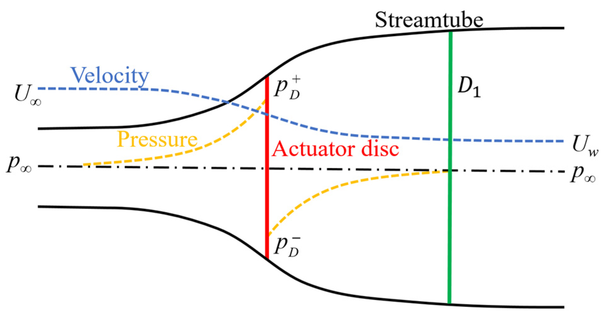
The wind turbine extracts energy from the incoming flow, resulting in a velocity deficit and turbulence intensity increase, which leads to a power loss and fatigue load increase. As shown in Figure 4, the wind turbine is idealized as an actuator disc [10]; because the wind speed is reduced after passing through the wind turbine, the stream tube gradually expands following the conservation of mass. The wind speed gradually decreases before it reaches the turbine rotor, the actuator disc plays the role of a pressure drop disc and the air pressure gradually recovers to atmospheric pressure, while the pressure recovery makes the wind speed continue to reduce following the Bernoulli equation; the turbine wake then gradually mixes with the surrounding stream. The wind speed of the free incoming flow is , the induced speed generated by the actuating disk in the flow direction is , where is the axial induction factor, and when the pressure recovers to atmospheric pressure the wind speed becomes
This indicates that half of the velocity deficit caused by the wind turbine occurs in the upstream of the wind turbine, and the other half occurs in the wake area with pressure recovery. Following this, with the continuous mixing of the external free flow, the wake velocity deficit is gradually recovered.

Figure 4.
The energy extracting stream-tube of a wind turbine.
As a combination of blade element theory and momentum theorem, Blade Element Momentum (BEM) theory is widely adopted in aerodynamics evaluation [10]. First, the velocity triangle of the blade element can be solved by the assumed axial induction factor. Then, based on the aerodynamic characteristics of the airfoil, the aerodynamic force of the turbine rotor can be obtained and a new axial induction factor can be calculated. Finally, through repeated iterations of the above two steps, the aerodynamic performance of the wind turbine can be obtained. By adopting different correction models, such as the dynamic stall model, tip loss model, root loss model, yaw correction, wake stall model, 3D polar correction, frozen turbulence model et al. [11], the BEM has a wide range of applicability in a variety of scenarios. However, the traditional BEM has a limitation when applied on FOWTs: it does not allow for 3D flow across various rotor radial elements, and this kind of 3D flow may be common in the flow field around FOWTs [12]. The typical literature, such as by Sebastian and Lackner [13], Veers et al. [14] and Ramos-García et al. [15], has pointed out that the rotor–wake interaction of FOWTs leads to the inapplicability of the momentum theory on FOWT aerodynamics prediction. For the past few years, the scientific community has been working on BEM for FOWTs with a much higher level of complexity. Considering the flow reversal around the turbine rotor, Ferreira et al. [16] establish a correction which improves the inapplicability of the momentum theory brought by the dynamic inflow of FOWTs. Recently, a representative study was conducted by Papi et al. [17]: four different aerodynamic models (Blade element momentum, Dynamic blade element momentum, Lifting-line free vortex wake, Actuator line model) are compared in their study and the results show that the aerodynamic performance of FOWTs can still be predicted by BEM with the dynamic wake model (DWM). The above analysis shows that, as a classic model, the BEM still plays an important role in FOWT aerodynamics calculation.
The wake of wind turbines can be roughly divided into a near wake and far wake [18]. The near wake is mainly characterized by the breaking and mixing of blade tip vortexes. As shown in Figure 5 [19], with the pressure difference between the pressure surface and the suction surface, the tip vortex is formed in the blade tip part, which results in the complex wake evolution. For wind turbines, the vortex is formed in the blade tip and blade root, and the blade tip vortex has a greater influence on turbine wake evolution [10]. With the rotation of the turbine rotor, the tip vortex falls off from the turbine blade in a typical helical vortex structure; the helical vortex structure shows an unstable evolution under perturbation [20,21,22,23]. Figure 6 [24] shows the vortex pairing, twining and breaking under the vortex-induced velocity. The near wake is directly affected by the wind turbine and the vortex structure generated by the turbine rotor plays a leading role in the near wake evolution; the geometric characteristics of the wind turbine blade profile, turbine hub and nacelle have a direct impact on the flow field in the near wake. The near wake has the characteristics of a highly complex, three-dimensional and non-uniform flow distribution. In contrast, the far wake is less affected by the details of the wind turbine, while the aerodynamic parameters of the wind turbine, such as the thrust coefficient and power coefficient, incoming flow condition and atmospheric stability, are the key factors affecting the development and evolution of the far wake. When the shear layer formed by the difference in wind speed between the wake and the external free flow expands to the wake center, the near wake basically ends [25]. The aerodynamic performance of wind turbine blades has a great influence on the near wake [26], while in the far wake region, the wake gradually expands and recovers, and behaves axisymmetrically, self-similarly and with a Gaussian distribution. The study of the wind turbine wake mainly focuses on velocity deficit and the resulting power loss, but an understanding of the wake vortex structure is also very critical, since the vorticity field and divergence field are essentially one of the manifestations of the velocity field.
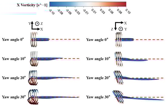
Figure 5.
Tip vortex of wind turbine [27].
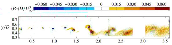
Figure 6.
Tip vortex evolution of wind turbine [24].
Wake meandering is also an important feature in the wind farm; this refers to the unsteady random oscillation of the wake center line of the wind turbine, which affects the safe and stable operation of downstream wind turbines. Wake meandering can be seen as the coupling effect between the ABL and the time-average turbine wake; studies indicate that the wake meandering phenomenon is mainly caused by the unstable vortex structure and velocity shear layer. A series of Dynamic Wake models have been proposed to describe this phenomenon [28,29]. The dynamic wake meandering model includes a steady wake velocity deficit model and another model describing the development process of a large-scale lateral and longitudinal meandering of the wind turbine wake. It is assumed that the meandering effect is driven by the large-scale turbulent structure in the atmospheric boundary layer. In order to realize such a turbulent structure, turbulent inflow information generated by the random turbulence generator is set in advance. Through the above settings, the dynamic wake meandering model (DWM) can realize the dynamic prediction of the wind turbine generation and load [30].
In large-scale wind farms, multiple wind turbines are centrally arranged [31] and the wakes of different wind turbines are superimposed, mixed and fused with each other, which makes the wind farm wake show complex characteristics such as a strong unsteady multi-scale effect and thermal-dynamic coupling [32]. For large wind farms, the internal flow tends to be stable and the power production of the wind turbines in this area becomes constant. In this fully developed area, the wind energy extracted by turbines mainly comes from the momentum exchange in the vertical direction [33], so the coupling of the turbine wake with the vertical structure of the atmospheric boundary layer (ABL) is much more important; this is called the “deep-array effect” [34]. In addition, the interaction between the atmosphere and large wind farms is very complex and the operation characteristics of large wind farms are greatly affected by the atmospheric stability, while the wake effect will also have an impact on large-scale flow [35].
Studies have shown that the wake area of large wind farms can cover tens or even hundreds of square kilometers, and that the disturbance caused by a wind farm will affect the characteristics of the atmosphere, and even the local weather and environment [36,37]. In general, the wind turbine wake effect is caused by design factors such as the wind turbine airfoil blade, nacelle and turbine hub, wind turbine blade pitch angle, rotation speed and other operating factors, atmospheric stability, wind speed and wind direction, etc. The wake effect is a complex and non-linear phenomenon; furthermore, it is difficult to predict the power loss caused by the wind farm wake effect. In particular, there is still a lack of flow research on floating wind farms while current research is still focused on single or tandem FOWTs.
The wake effect is a concern of wind farm micro-sitting and control strategy optimization [38]. In order to evaluate the wake effect in wind farms with a lower computational cost, an analytical wake model is needed. In an analytical wake model, the turbulence intensity is generally calculated from two items, the ambient turbulence intensity and the added turbulence intensity caused by the wind turbine [39], and the total wake velocity deficit is obtained from the momentum conservation and wake expansion empirical formula. The analytical model of a wind turbine wake is the key to determining the optimal layout effect, and the establishment of the analytical model of a wind turbine wake requires a deep understanding of the development and evolution mechanism of the wake. Based on mass conservation and top-hat velocity distribution, the Jensen model is the most adopted analytical wake model [40]. However, top-hat distribution has defects in describing wake radial wind velocity distribution and Gaussian distribution is introduced, as described by Bastankhah and Porté-Agel [41], Gao et al. [42], Sun and Yang [43], Ge et al. [44] and Xie and Archer [45]. In addition to the analytic wake model, the “top-down” model is also an important part of describing the internal flow in a large-scale wind farm and it gives the velocity distribution over the vertical direction of the wind farm boundary layer [33,34,46].
The wind farm control strategy is mainly implemented from two aspects [47]: First, the induction factors of wind turbines can be controlled [48]. The wake velocity deficit of upstream wind turbines is reduced by limiting their ability to extract wind energy, so as to improve the power generation of downstream wind turbines. When the operation status of wind turbines in wind farms is reasonably controlled, the overall power generation of the wind farm can be enhanced; the specific means include adjusting the pitch angle of the rotor speed, etc. Active yaw control is another way to enhance the total power generation [49]. When the wind turbine is yawing or pitching, the turbine wake will be deflected, so that the downstream wind turbine is less affected by the upstream wind turbine wake, in order to improve the overall power generation of the wind farm.
3. Experiment Study of Wind Turbine Wake
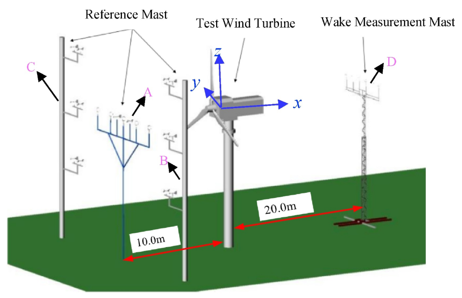
In order to obtain credible wind turbine wake data, field measurements and wind tunnel experiments are conducted in the turbine wake’s study. In typical field experiments, a wind mast and LiDAR are most widely adopted. In Li et al.’s studies [50,51], the wind mast was installed upstream and downstream of the test wind turbine (shown in Figure 7), the incoming wind and wake were measured by a three-cup anemometer and ultrasonic anemometer, and the power performance and wake characteristics of wind turbines under different incoming wind speed and tip speed ratios were analyzed. This method of measuring the wind turbine wake by a wind mast can obtain high-frequency wind speed information and can effectively evaluate the wind turbine wake. Böhme et al. [52] used four wind masts distributed in wind farms to evaluate the impact of wake effects in wind farms and the impact of the wake effect was analyzed. The advantage of the wind mast is that it can take long-term and stable measurements, which are very important for the evaluation of a wind farm operation. However, the wind mast data are only measured at certain single points; furthermore, the wind mast cannot be moved after it has been built, which brings some limitations to wake characteristics analysis.

Figure 7.
Experimental apparatus and schematic view of the whole field experiment [50].
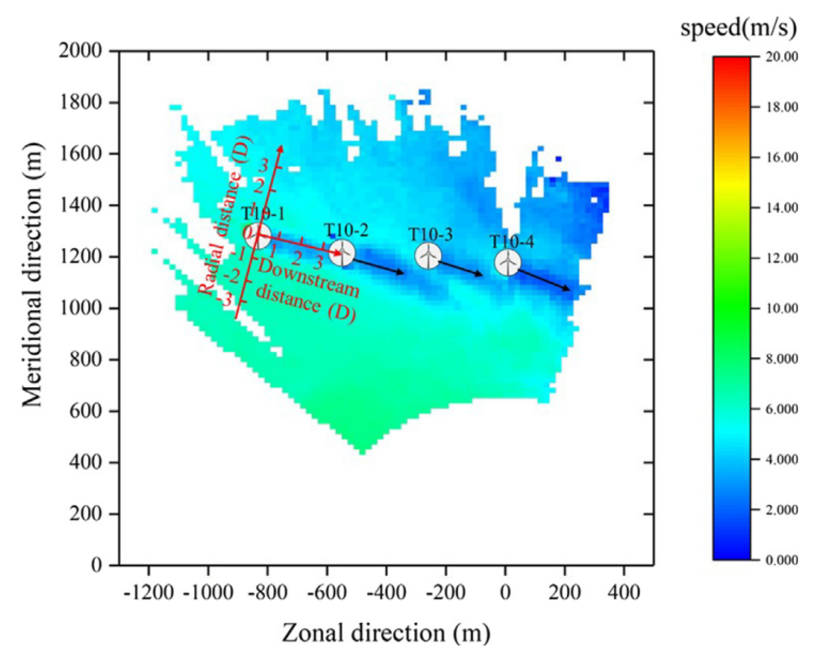
Recently, LiDAR (light detection and ranging) has been widely used for wind farm wake measurements. The measuring principle of LiDAR is to measure the wind speed using the interaction between the laser and aerosol particles in the atmosphere. The echo signal generated by the Doppler shift effect between the laser and aerosol particles is compared with the transmitted signal to calculate information such as the atmospheric wind speed and wind direction. Compared with the wind mast, the LiDAR’s installation is more flexible, and it can carry out a large range of three-dimensional scanning of wind farms and obtain abundant wake measurements. Gao et al. [53] adopted LiDAR to measure the turbine wake in wind farms in a complex terrain (shown in Figure 8). Combined with SCADA (supervisory control and data), the power performance of wind turbines under the impact of a wake effect was analyzed. The research shows that the power loss caused by the wake effect is very obvious even in complex terrain, and the wake evolution is more complex. Lungo [54] used LiDAR to measure the turbine wake of a 2 MW wind turbines under different atmospheric stabilities, and the experiment showed that wake recovery was faster in an unstable atmosphere. Kumer et al. [55] used LiDAR to measure the turbulent structure of a turbine wake and compared it with the atmospheric turbulent structure. Their study shows that the vortex structure driven by convection was similar to the vortex structure in the wake of wind turbines, and the atmospheric convection was not conducive to the fatigue load of wind turbines. More diverse flow field information can be obtained through LiDAR measurement, and it is widely adopted in wake impact evaluation and wake model validation [56,57], but the resolution of LiDAR measurements is relatively low, which is not conducive to the analysis of a wake evolution mechanism.
In addition to these common measurement methods, some new techniques have also been applied to wake measurements. Abraham et al. [58] used super-large-scale particle image velocimetry (SLPIV) to measure the near wake of the wind turbine. Subramanian et al. [59] used a drone with sensors to measure the wake velocity deficit distribution and turbulent kinetic energy with high accuracy, and analyzed the anisotropy of the turbulence intensity and shear wind speed. Unlike the wind tunnel wake measurement experiment, the tracer particles adopted in this experiment were snowflakes. The field experiment can well reflect the evolution of the turbine wake and its impact on the power performance of wind turbines. Meanwhile, the wind field experiment also has certain limitations: the atmospheric wind environment is uncontrollable, so it is almost impossible to measure the wind turbine wake under all working conditions; Measuring instruments may have limitations in some scenarios, for example, when there is a lack of aerosol particles in the air, or when rainy, foggy or snowy weather h causes the laser to be unable to emit enough distance and the laser wind radar cannot work. Furthermore, in order to obtain enough wind turbine wake data, wind farm wake measurement experiments generally require a long experiment period and high experiment cost [60]. The above various field measurement techniques complement each other and provide a database for a wake study.

Figure 8.
Wake profile scanned by LiDAR [61].
Figure 8.
Wake profile scanned by LiDAR [61].
Compared with field measurements, the boundary conditions of a wind tunnel experiment are more controllable. However, the mismatch between hydrodynamics and aerodynamics of the scale FOWT model is an urgent issue to be solved.
The Reynolds number is an important dimensionless number in wind tunnel experiments and its physical meaning is the ratio of inertia force to viscous force
where is the density, is the fluid velocity, is the characteristic length, and is the dynamic viscosity coefficient. The similarity of the Reynolds number is the basic criterion for wind tunnel experiments, which ensures that the aerodynamic performance of wind turbine models is similar to that of prototype turbines. The thrust coefficient is the key factor affecting the wake velocity deficit, and its physical meaning is the dimensionless wind turbine thrust
where is the turbine thrust and is the rotor sweep area. Li et al. [62] studied wake characteristics under different turbulence intensity and wind shear conditions in a wind tunnel with active turbulence grids and wind shear generating devices, and the results indicate that inflow turbulence promoted a wake velocity deficit recovery and expansion. The wake characteristics of a wind turbine located on a steep slope were measured by Arslan et al. [63]; geometry changes in the steep slope led to changes in incoming wind turbulence intensity, further affecting the wake recovery and wake meandering of wind turbines. In Dou et al.’s study [64,65,66], a small-scale wind turbine model is adopted in wind tunnel experiments and wake characteristics are measured; furthermore, an analytical wake model is proposed. Bastankhah and Porte-Agel [67] used a SPIV system to conduct wake measurements on the small wind turbine model under a yaw state, and analyzed the counter-rotating vortex pair that affects wake development. Zong and Porte-Agel [67] conducted a wind tunnel experiment on a three-row micro wind farm. By changing the yaw angle of wind turbines, the wake impact on downstream turbines can be reduced, and the overall power of the wind farm can be increased by up to 18%. All the literature cited above focuses on wind tunnel experiments on fixed wind turbines. However, it should be emphasized that FOWTs operate in a vastly different environment, one characterized by the complex and dynamic coupling of wind, waves, and currents. In contrast to a bottom-fixed wind turbine, FOWTs are continuously affected by water-related factors such as waves and ocean currents. Therefore, hydrodynamic performance plays a crucial role in the study of FOWTs and has emerged as a key aspect that cannot be overlooked and demands in-depth exploration. In the wind tunnel experiment on FOWTs, the Froude number is another important criterion [68]; its physical meaning is the ratio of inertial force to gravitational force
where is the fluid velocity, is the gravity acceleration, and is the characteristic length. The Reynolds number and Froude number correspond to aerodynamic performance and hydrodynamic performance, respectively, but the contradiction between these two criteria leads to the dilemma of the wind tunnel experiment [69].
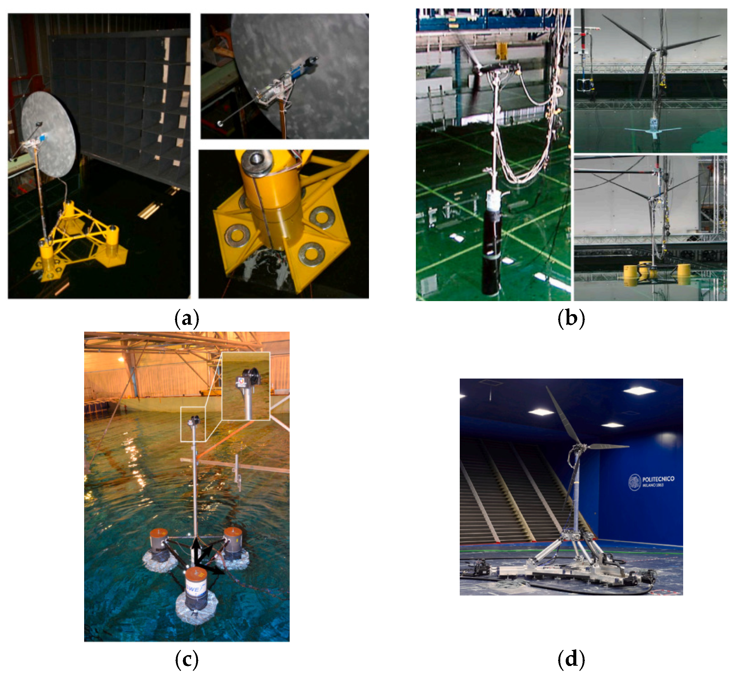
In order to solve the contradiction between the Reynolds number and Froude number, there are two main feasible ways at present: In the wave basin tests, the hydrodynamic similarity is ensured, and the thrust disc, ducted fan and specialized blade design are adopted to meet the thrust similarity, but the power performance similarity cannot be satisfied; in the wind tunnel experiment, the aerodynamic performance is guaranteed, and the effect of the hydrodynamic load is simulated by the six-degree-of-freedom platform. The wave basin tests mainly focus on the structural response of FOWTs, in which the hydrodynamic response accounts for a large proportion of the structural load. Therefore, the wave basin tests are generally conducted according to the criterion of the Froude number, but at the same time, the decrease in the Reynolds number inevitably leads to a decrease in aerodynamic performance. As shown in Figure 9a, in the early research Cermelli et al. [70] used a thrust disc to simulate the aerodynamic load of FOWTs and the wave basin test was guided by the Froude number criterion. This experimental facility can simulate the motion response of floating wind turbines, but because the thrust disc can only simulate the axial thrust and cannot reproduce the load in other directions, there are some limitations to this study. To validate FAST software developed by NREL, the U.S. Department of Energy funded the DeepCwind project (shown in Figure 9b). Compared with the thrust disc, this scaled model can simulate the turbine rotation load, but the geometric scaled model cannot guarantee the similarity of thrust and aerodynamic performance. In addition to a geometrically similar blade design, the thrust similarity is also widely used in the wave basin test [71,72], which ensures the similarity of structural load between the scale wind turbine and the prototype wind turbine. Recently, a series of new model blade design methods were proposed [73,74] for scale FOWT experiments in our previous studies, which could ensure the similarity of both the thrust coefficient and the power coefficient; this is a significant improvement on scale wind turbine experiment techniques.
Furthermore, a ducted fan was also adopted to simulate the aerodynamic load [75] in a wave basin test (shown in Figure 9c). While in the wind tunnel experiment, the platform motion of FOWTs is simulated by the six-degree-of-freedom platform, typical 6-DOF FOWT wind tunnel models [76] are shown in Figure 9d. In summary, some breakthroughs have been made in FOWT experiment approaches, especially the “Hardware in the loop” technique, but there are still gaps in conducting a wake measurement with the simultaneous similarity between aerodynamic and hydrodynamic characteristics.

Figure 9.
Different kinds of scale FOWT model: (a) a thrust disk is used to simulate the aerodynamic load of the wind turbine [70]; (b) FOWT model test with geometry-scaled turbine blades [77]; (c) the ducted fan is used to simulate the aerodynamic load of the wind turbine [75]; (d) FOWT models with six degrees of freedom platform [69,76].
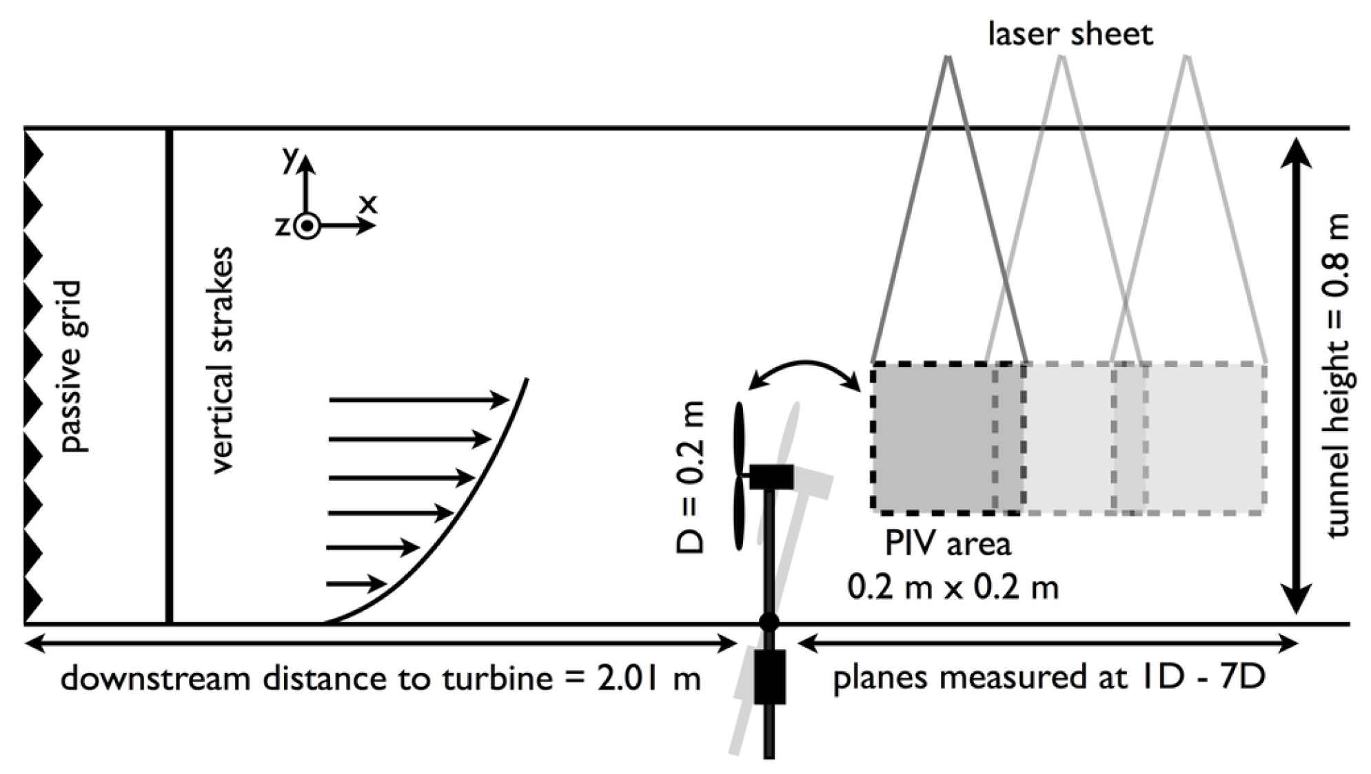
At present, most experimental studies on FOWTs wake studies are wind tunnel experiments, and there is no strict aerodynamic and hydrodynamic coupling. Rockel et al. [78,79] adopted PIV (particle image velocity) to measure the FOWT wake under pitch motion (shown in Figure 10). The wind tunnel experiment setup is shown in Figure 10. The wind turbine is installed on a universal joint, and a 650 g counterweight block is installed below the wind turbine. Under the wind impact, the FOWT model makes a pitch motion. However, the platform motion is uncontrollable, the average pitch motion angle of the FOWT is 17.6° and the standard deviation in pitch motion angle is 0.4. Results shows that the pitch motion leads to an upward wake deflection, which causes a greater fatigue load and higher power loss on downstream wind turbines. It is worth noting that the average pitch motion angle is far beyond the normal pitch motion range. Bayati et al. [80,81] adopted a scaled DTU 10 MW FOWT with a scale ratio of 1/75 to conduct the wind tunnel experiment and the near wake was measured by a hot wire anemometer; furthermore, the FOWT aerodynamic performance was analyzed coupled with the wake measurement. In Feist et al.’s study [82], the experimental data show that the motion of a floating platform increases the turbulence intensity of the wake. Fu et al. [83] adopt PIV and a hot-wire anemometer to measure the FOWT wake under pitch and roll motion; results show that the motion amplitude and motion frequency have a great impact on the wake evolution. Theoretical and experimental approaches are adopted in Duan et al.’s study [84]; they proposed a critical Strouhal number to distinguish the power performance and wake state. A summary of experimental approaches is shown in Table 3. In general, there are relatively few experimental studies on the FOWT wake and a qualitative study of wake characteristics is the focus.
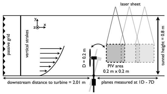
Figure 10.
The wake wind tunnel setting of FOWT in reference [78].
Table 3.
Summary table of experimental approaches.
Overall, progress has been made in FOWT wake measurements, but there are still some obstacles that need to be addressed: First, there is an absence of FOWT field wake measurements. Field tests are expensive, especially for FOWTs; furthermore, there are few suitable locations to conduct a FOWT wake measurement campaign. However, a study of FOWT wake evolution under a complex atmospheric boundary layer and the verification of a FOWT wake model all require field measurement data. Second, the contradiction between the Reynolds number and the Froude number leads to the dilemma of a scaled experiment, which results in the aerodynamics and hydrodynamics of a scaled FOWT being unable to be similar at the same time. Further, wake measurements of FOWTs are generally conducted in a wind tunnel with an imposed sinusoidal platform motion. To overcome these gaps in wake measurements, the “Hardware in the loop” technique is proposed, but needs to be further improved.
4. Numerical Simulation Study of Wind Turbine Wake
For the hydrodynamics of FOWTs, viscous damping at the natural frequency is the most fundamental aspect and it is typically obtained from decay tests [85]. In Zhang et al.’s study [86], the interactions of 3 h irregular waves and a moored DeepCwind platform are simulated, and a numerical approach coupling a far-field wave using high-order spectral (HOS) to a near-field CFD is adopted; their simulation results show a good agreement with the experimental data. Lagrangian smoothed particle hydrodynamics (SPH) is adopted in Wang et al.’s study [87]; the structural and hydrodynamic response of FOWTs under impulsive breaking waves was studied and the result shows that the waves breaking do not have a significant impact on the rigid body motions. In Rao et al.’s study [88], the flow field of spars with heave plates with different heave plate parameters is simulated and heave damping characteristics are analyzed. Overall, the viscous damping of the platform is the focus of FOWT hydrodynamics.
For the aerodynamics of FOWTs, the rotor loading and power performance are the focus [12]. The floating platform motions bring an additional wind speed to the turbine blade, which leads to the aerodynamic instability of the turbine rotor. Using the Unsteady Reynolds-Averaged Navier–Stokes (URANS) method, a numerical simulation of the near wake and aerodynamics of FOWTs is conducted in Sun’s study [89]; results indicate that the flow separation region over the blade surface is enlarged. Adopting the free vortex wake (FVW), Zhou et al. [90] conducted a study of the unsteady aerodynamics of FOWTs; results indicate that the trailing vortex induction and airfoil dynamic stall have a great impact on power performance. In Dong and Viré’s study [91], the aerodynamics of FOWTs are simulated using FVM, results show that the rotor experiences alternative onset of the windmill state, vortex ring state, and propeller state, besides the largest load fluctuations occur at the vortex ring state boundaries. In addition to the aerodynamic performance of individual FOWTs, the FOWT aerodynamics under the wake impact have also received great attention. Arabgolarcheh et al. [92] conducted a turbine interaction simulation using an actuator line model; results show that the wake of the upstream wind turbine exacerbates the aerodynamic performance oscillation of downstream wind turbines.
The hydrodynamics and aerodynamics are not isolated, and they interact with each other. Under the environmental load and a mooring force, the floating platform has six degrees of freedom motions, which bring changes in the relative wind speed of the turbine rotor as well as the turbine aerodynamics. At the same time, the change in aerodynamics has an impact on platform motions; the hydrodynamics are then affected. Cai et al. [93] found that a decrease in wind speed increases the amplitude of the surge response while decreasing the amplitude of the heave response. Additionally, at lower wind speeds, an increase in the wave height amplifies the platform’s motion response, while a variation in the aerodynamic thrust is slightly influenced by the change in the platform’s motion amplitude. In Alkhabbaz et al.’s study [94], high-fidelity CFD simulation of FOWTs is conducted; results show that the wake recovery of FOWTs is faster than that of bottom-fixed turbines when it is under surge motion. Moreover, in Liu et al.’s study [9], the power generation can be increased through reasonable control of the platform motion.
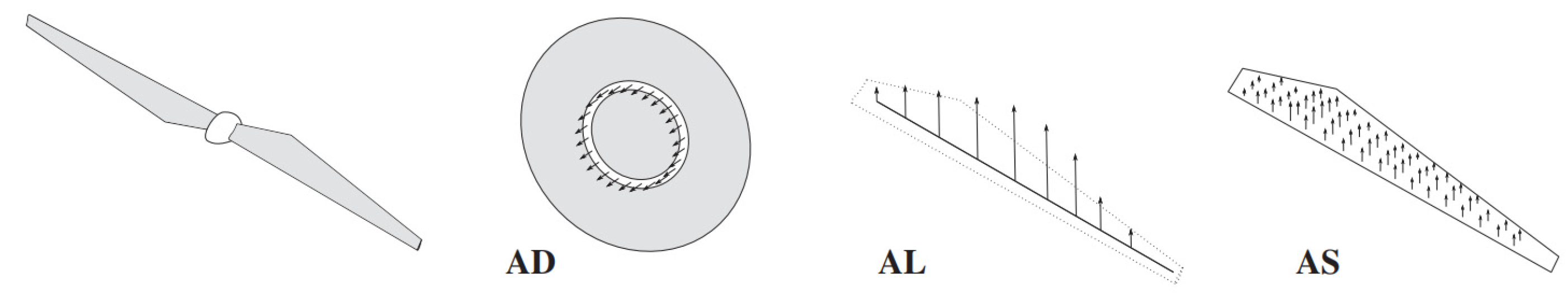
The wind turbine wake is an extension of wind turbine aerodynamics and its simulation result is closely related to the wind turbine modeling methods adopted. As summarized in Table 3, different simulation approaches have been adopted in FOWT wake studies. The modeling methods for wind turbines in CFD simulations include the full rotor model (FRM) and actuator model. The full rotor model (FRM) refers to building the geometric model of the wind turbine [95,96]; however, it is not practical to apply this method to numerical simulation of a wind farm, so it is generally used for the study of turbine aerodynamic performance and near-wake simulation. In the actuator method, the force source term is added to the Navier–Stokes equation to represent the force of the turbine blade; in this way, the computational cost can be greatly reduced on the premise of ensuring the accuracy of the wake simulation. According to the simplification of wind turbines (shown in Figure 11), actuator methods are classified into an actuator disc method (ADM), actuator line method (ALM) and actuator surface method (ASM) [97]. The ADM has the lowest requirement of computing resources, so it is widely adopted in the flow field simulation of wind farms [98,99]. Compared with the ADM, the ALM can provide more detailed wake characteristics and the blade tip vortex can be clearly simulated [100,101]. In the ASM, the blade surface pressure source term is distributed on the actuator surface, which further improves the simulation precision; meanwhile, the computation cost increases accordingly [102]. Considering the advantages and disadvantages of these methods, the actuator method has been widely adopted, and ADM and ALM are the most commonly adopted methods in turbine wake studies. Table 4 shows the summary table of simulation approaches, the advantages and weaknesses of these approaches are presented.

Figure 11.
Illustration of the actuator disk (AD), line (AL) and surface (AS) concept [97].
Table 4.
Summary table of simulation approaches.
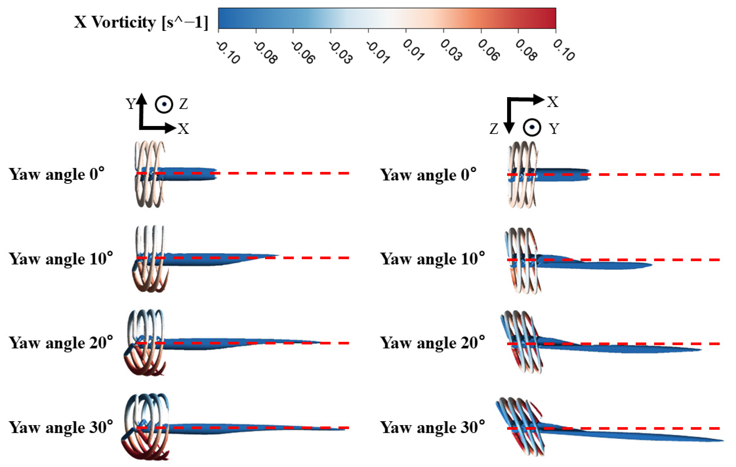
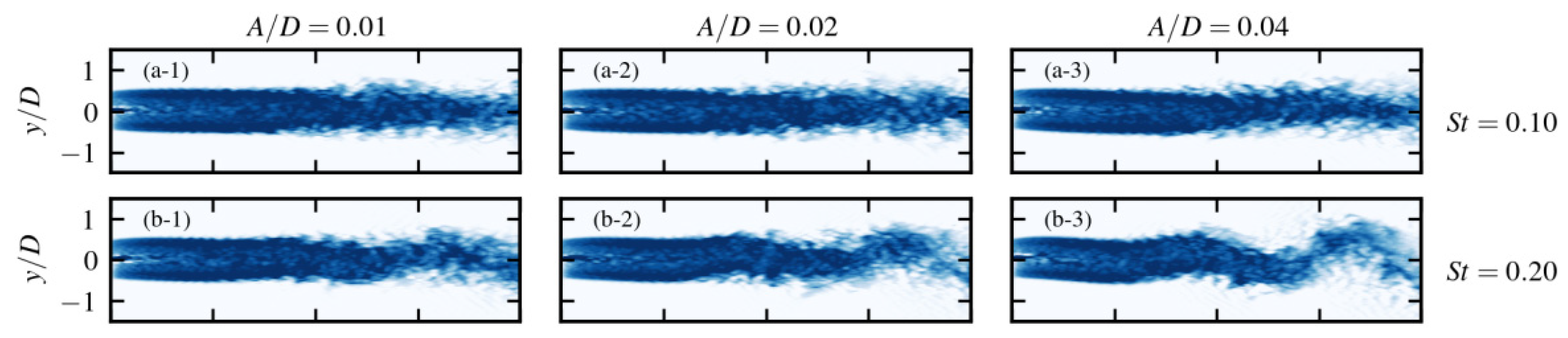
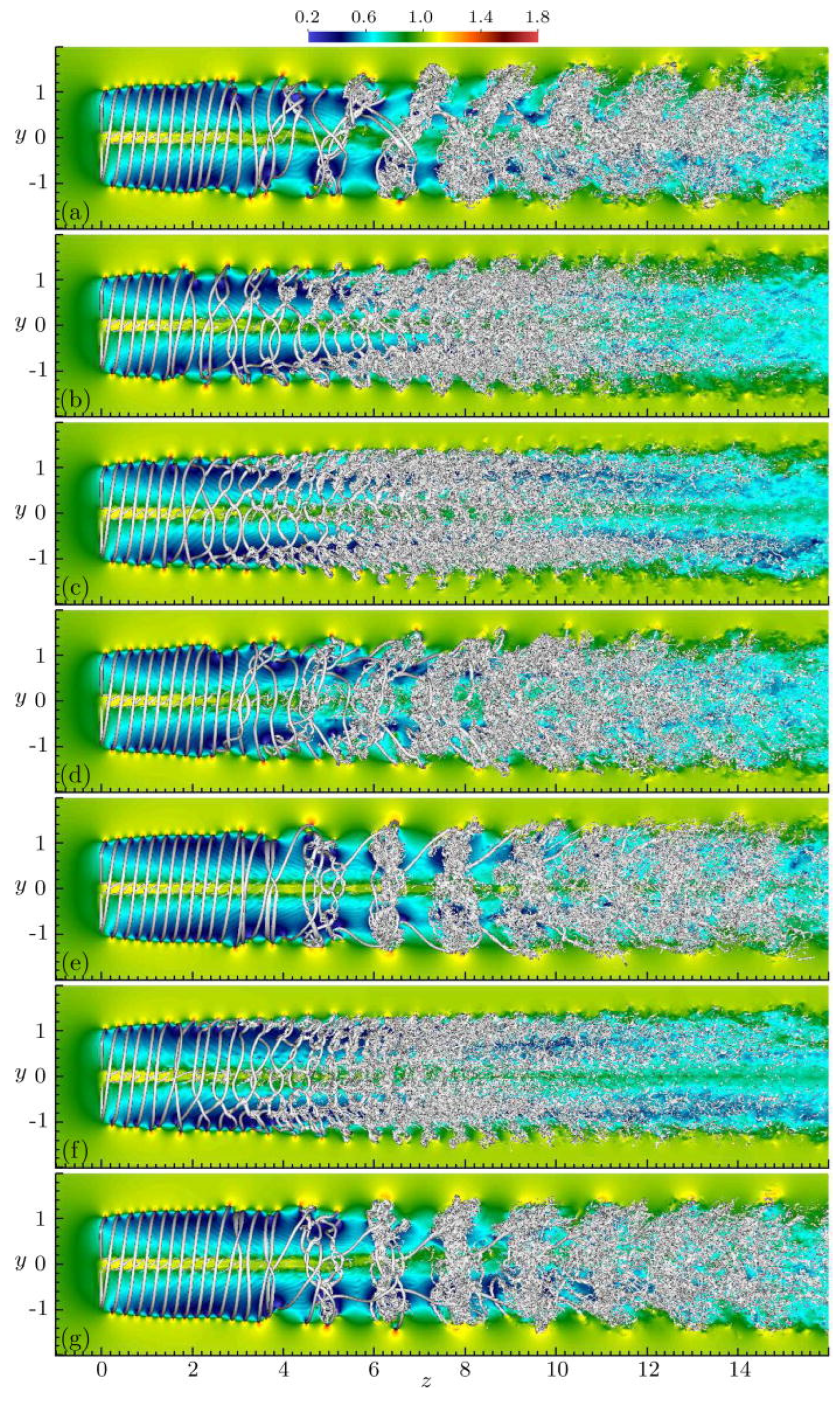
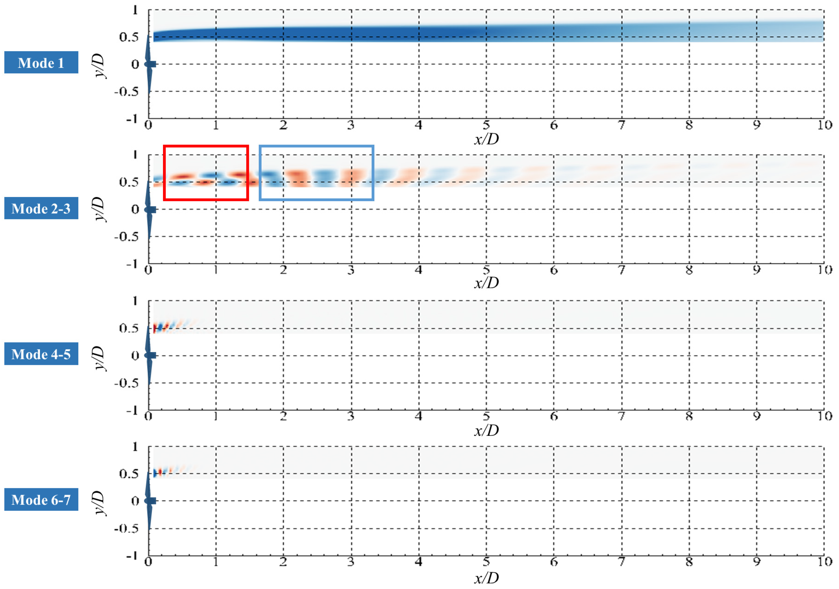
At present, progress has been made in numerical simulation of the FOWT wake. The aerodynamic performance and near wake of FOWTs are simulated using the FRM method in Lin et al.’s study [103]; results show that the platform movement strengthened the vortex system which leads to the wake asymmetry. Chen et al. [104] analyzed the near wake and aerodynamic characteristics simulated by the FRM; their study indicates that the increase in platform motion frequency and amplitude exacerbated the aerodynamic performance instability. Li et al. [105] analyzed the wake meandering characteristics of FOWTs under sway motion through ASM simulations (shown in Figure 12); their research shows that the wake meandering amplitude may be one order of magnitude higher than the initial disturbance. Wise and Bachynski [109] simulated the wake meandering of FOWTs on different types of platforms using FAST.Farm; turbine loads under the impact of awake were also analyzed. Recently, the vortex ring structure has been proven to be one of the most representative and significant wake characteristics of a FOWT wake. Kleine et al. [110] conducted a fine simulation of a FOWT wake under different platform movements (shown in Figure 13) and the simulation results were analyzed using instability theory; it can be seen that a different typical vortex ring structure is formed by the interaction of the tip vortex. In a previous study [106], the evolution mechanism of the vortex ring structure is analyzed through modal decomposition (shown in Figure 14). The area in the red box shows the the evolution process of blade tip vortices and in the blue box the vortex ring structure have been formed; Furthermore, the vortex ring generation period has been proven to be the platform motion period
further, based on the wake linear expansion hypothesis, momentum conservation and empirical correction, a semi-empirical model for the vortex ring movement is established; thus, the spacing of adjacent vortex rings can be obtained. The momentum exchange brought by the vortex ring is conducive to wake recovery; Wang et al. [111] also pointed out that platform oscillation frequency is the key to wake recovery, which includes the relationship between platform motions, the vortex ring and wake recovery. Arabgolarcheh et al. [112] conducted a series of FOWT wake simulations using the ALM; results show that the vortex rings have a great impact on aerodynamic loads and power generation performance. Current studies have shown that the velocity induced by the vortex ring structure is the key to understanding FOWT wake evolution, and its development in a complex atmospheric boundary layer has not been thoroughly studied.
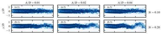
Figure 12.
(a-1–a-3,b-1–b-3) FOWT wake meandering with different platform movements [105].
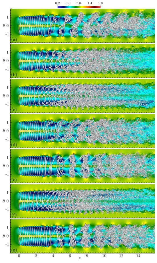
Figure 13.
(a–g) FOWT wake meandering with different platform movements [110].
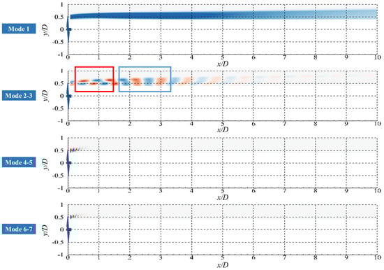
Figure 14.
DMD modes of vorticity in the FOWT wake [106].
There are still gaps in the study of the FOWT wake. In the typical study from the OC6 project Phase III, Cioni et al. [113] conducted a series of numerical simulations using different approaches with varying levels of fidelity; the tip vortices evolution in the near wake is the focus of this work; furthermore, results indicate that, for a FOWT with platform motions, the wake recovery may not be promoted but even limited, which is outside the expectation of previous studies [80,114]. This indicates that the understanding of wake characteristics is still not unified and that the diffusion mechanism of wake turbulent structures in different inflow flows under various platform motions needs to be further discussed. Furthermore, with more detailed flow data, wake meandering, wake velocity deficit fluctuation and the wake vortex ring structure have been proven to be the typical characteristics of a FOWT wake [114]; however, the evolution of a FOWT wake under a complex atmospheric boundary layer and FOWT farm flow field simulations needs further study [115].
5. Conclusions
This review focuses on the experimental methods, simulation approaches and wake characteristics of a FOWT wake. With the rapid development of offshore wind energy, the deep sea has attracted more and more attention. The platform movement leads to a complex FOWT wake evolution, including wake recovery acceleration, velocity deficit fluctuations, wake deformation and wake meandering.
The fact that Reynolds number similarity and Froude number similarity cannot be satisfied at the same time is the dilemma in scaled FOWT experiments. In order to solve this problem, improved scaled criteria and the physical replacement of a turbine rotor are proposed; however, there are still gaps between the scaled experiment and field measurement. A wind tunnel experiment with a 6-DOF platform is the main way to obtain FOWT wake experiment data. The wake measurement indicates that the movement of the platform enhances the wake recovery and wake deformation.
In FOWT wake simulation, the FOWT platform is generally set to a forced sinusoidal motion, which lacks the coupling of aerodynamic and hydrodynamic; however, the evolution mechanism of a FOWT wake is universal. Simulation results show that the vortex ring structure has been proven to be one of the most representative and significant wake characteristics of a FOWT wake. Recently, an instability theory and modal decomposition technique were applied to the analysis of the FOWT wake evolution mechanism. The formation of a vortex ring was revealed, leapfrogging evolution is shown in the adjacent helical vortices while the adjacent helical vortices of an instable part fuse with each other and form a vortex ring.
6. Limitations of This Work and Future Recommendations
This paper gives a comprehensive review of experimental methods, simulation approaches and wake characteristics of a FOWT wake; however, the limitations of this review need to be presented. At present, the study of a FOWT wake is in its initial stages and there is a lack of relevant research on floating wind farms. Furthermore, there is little research on the analytical FOWT wake model [116,117]; the characterization of dynamic wake characteristics of a floating wake is the focus of modeling. Therefore, this paper does not carry out a detailed review of this aspect. In addition, the emergence of some new floating offshore wind power technologies, such as the floating twin-rotor wind turbine system [84,118,119], will also bring new research challenges.
According to the current study status, here are some future recommendations:
(1) In the aspect of experiment measurements, a technical improvement in the “Hardware in the loop” is needed to overcome the contradiction between the Reynolds number and the Froude number. Accurate reproduction of hydrodynamics and aerodynamics is the key to this technology and accurate and real-time simulation and experiment coupling are its technical difficulties. With a better reproduction of the coupling between aerodynamics and hydrodynamics, the wake evolution mechanism can be further revealed. Furthermore, field measurements of a FOWT wake are urgently needed.
(2) In the aspect of numerical simulation, a high-efficiency and high-fidelity numerical simulation technique combining CFD and AI will be the focus. The development of this new technique relies on a deep understanding of the flow mechanism to provide a physical framework and requires a large amount of experimental and numerical simulation data to train the model. This kind of fast simulation technology will greatly improve the micro-sitting and control strategy optimization of floating wind farms.
Author Contributions
Conceptualization, X.C., T.W., C.C., J.L. and Q.L.; investigation, X.G., N.G. and Q.L.; resources, C.C. and Q.L.; writing—original draft preparation, X.C., T.W. and C.C.; writing—review and editing, C.C. and Q.L.; project administration, Q.L.; funding acquisition, Q.L. All authors have read and agreed to the published version of the manuscript.
Funding
This work is financially supported by the Strategic Priority Research Program of the Chinese Academy of Sciences (Grant No. XDC0190200), National Natural Science Foundation of China (No. 52106281).
Conflicts of Interest
Author Xiaoxu Chen and Jianshuang Liu were employed by the company CRRC Qi Hang New Energy Technology Co., Ltd. Author Naizhi Guo was employed by the company CHN ENERGY Economic and Technological Research Institute Co., Ltd. The remaining authors declare that the research was conducted in the absence of any commercial or financial relationships that could be construed as a potential conflict of interest.
References
- Nasouri, M.; Delgarm, N. Investigating the Role of Bushehr Nuclear Power Plants (BNPPs) in Line with Achieving the Perspective of Sustainable Energy Development in Iran. J. Therm. Sci. 2022, 31, 1392–1406. [Google Scholar] [CrossRef]
- GWEC. Global Wind Report 2024. Available online: https://gwec.net/global-wind-report-2024/ (accessed on 16 April 2024).
- Gao, X.; Zhou, K.; Liu, R.; Ma, W.; Gong, X.; Zhu, X.; Wang, Y.; Zhao, F. Aerodynamic characteristics of wind turbines considering the inhomogeneity and periodic incentive of wake effects. Energy 2024, 310, 133275. [Google Scholar] [CrossRef]
- Porté-Agel, F.; Bastankhah, M.; Shamsoddin, S. Wind-Turbine and Wind-Farm Flows: A Review. Bound.-Layer Meteorol. 2020, 174, 1–59. [Google Scholar] [CrossRef] [PubMed]
- Archer, C.L.; Vasel-Be-Hagh, A.; Yan, C.; Wu, S.; Pan, Y.; Brodie, J.F.; Maguire, A.E. Review and evaluation of wake loss models for wind energy applications. Appl. Energy 2018, 226, 1187–1207. [Google Scholar] [CrossRef]
- Hasager, C.B.; Rasmussen, L.; Peña, A.; Jensen, L.E.; Réthoré, P.-E. Wind Farm Wake: The Horns Rev Photo Case. Energies 2013, 6, 696–716. [Google Scholar] [CrossRef]
- Edwards, E.C.; Holcombe, A.; Brown, S.; Ransley, E.; Hann, M.; Greaves, D. Trends in floating offshore wind platforms: A review of early-stage devices. Renew. Sustain. Energy Rev. 2024, 193, 114271. [Google Scholar] [CrossRef]
- Society for Underwater Technology. South West–Offshore Floating Wind–Design and Installation–Registrations Now Closed. 2018. Available online: https://www.sut.org/event/south-west-offshore-floating-wind-design-and-installation/ (accessed on 14 June 2018).
- Liu, J.; Cai, C.; Song, D.; Zhong, X.; Shi, K.; Chen, Y.; Cheng, S.; Huang, Y.; Jiang, X.; Li, Q. Nonlinear model predictive control for maximum wind energy extraction of semi-submersible floating offshore wind turbine based on simplified dynamics model. Energy 2024, 311, 133356. [Google Scholar] [CrossRef]
- Burton, T.; Jenkins, N.; Sharpe, D.; Bossanyi, E. Wind Energy Handbook; John Wiley & Sons, Ltd.: Hoboken, NJ, USA, 2011. [Google Scholar]
- Hjort, S. Non-Empirical BEM Corrections Relating to Angular and Axial Momentum Conservation. Energies 2019, 12, 320. [Google Scholar] [CrossRef]
- Micallef, D.; Rezaeiha, A. Floating offshore wind turbine aerodynamics: Trends and future challenges. Renew. Sustain. Energy Rev. 2021, 152, 111696. [Google Scholar] [CrossRef]
- Sebastian, T.; Lackner, M.A. Characterization of the unsteady aerodynamics of offshore floating wind turbines. Wind Energy 2013, 16, 339–352. [Google Scholar] [CrossRef]
- Veers, P.; Dykes, K.; Basu, S.; Bianchini, A.; Clifton, A.; Green, P.; Holttinen, H.; Kitzing, L.; Kosovic, B.; Lundquist, J.K.; et al. Grand Challenges: Wind energy research needs for a global energy transition. Wind Energy Sci. 2022, 7, 2491–2496. [Google Scholar] [CrossRef]
- Ramos-García, N.; Kontos, S.; Pegalajar-Jurado, A.; Horcas, S.G.; Bredmose, H. Investigation of the floating IEA Wind 15 MW RWT using vortex methods Part I: Flow regimes and wake recovery. Wind Energy 2022, 25, 468–504. [Google Scholar] [CrossRef]
- Ferreira, C.; Yu, W.; Sala, A.; Viré, A. Dynamic inflow model for a floating horizontal axis wind turbine in surge motion. Wind Energy Sci. 2022, 7, 469–485. [Google Scholar] [CrossRef]
- Papi, F.; Jonkman, J.; Robertson, A.; Bianchini, A. Going beyond BEM with BEM: An insight into dynamic inflow effects on floating wind turbines. Wind Energy Sci. 2024, 9, 1069–1088. [Google Scholar] [CrossRef]
- Ainslie, J. Development of an eddy viscosity model for wind turbine wakes. In Proceedings of the BWEA Wind Energy Conference (British Wind Energy Association), Oxford, UK, 27–29 March 1985. [Google Scholar]
- Merzkirch, W. Flow Visualization II; Hemisphere Publishing Corporation: London, UK, 1982. [Google Scholar]
- Gupta, B.P.; Loewy, R.G. Theoretical Analysis of the Aerodynamic Stability of Multiple, Interdigitated Helical Vortices. AIAA J. 1974, 12, 1381–1387. [Google Scholar] [CrossRef]
- Quaranta, H.U.; Bolnot, H.; Leweke, T. Long-wave instability of a helical vortex. J. Fluid Mech. 2015, 780, 687–716. [Google Scholar] [CrossRef]
- Quaranta, H.U.; Brynjell-Rahkola, M.; Leweke, T.; Henningson, D.S. Local and global pairing instabilities of two interlaced helical vortices. J. Fluid Mech. 2019, 863, 927–955. [Google Scholar] [CrossRef]
- Widnall, S.E. The stability of a helical vortex filament. J. Fluid Mech. 1972, 54, 641–663. [Google Scholar] [CrossRef]
- Lignarolo, L.E.M.; Ragni, D.; Scarano, F.; Ferreira, C.J.S.; van Bussel, G.J.W. Tip-vortex instability and turbulent mixing in wind-turbine wakes. J. Fluid Mech. 2015, 781, 467–493. [Google Scholar] [CrossRef]
- Haans, W.; Sant, T.; van Kuik, G.; van Bussel, G. Measurement of tip vortex paths in the wake of a HAWT under yawed flow conditions. J. Sol. Energy Eng. 2005, 127, 456–463. [Google Scholar] [CrossRef]
- Dong, G.; Qin, J.; Li, Z.; Yang, X. Characteristics of wind turbine wakes for different blade designs. J. Fluid Mech. 2023, 965, A15. [Google Scholar] [CrossRef]
- Wang, T.; Cai, C.; Wang, X.; Wang, Z.; Chen, Y.; Hou, C.; Zhou, S.; Xu, J.; Zhang, Y.; Li, Q. Evolution mechanism of wind turbine wake structure in yawed condition by actuator line method and theoretical analysis. Energy Convers. Manag. 2023, 281, 116852. [Google Scholar] [CrossRef]
- Ye, S.; Wang, Q.; Mu, Y.; Luo, K.; Fan, J. Loads and fatigue characteristics assessment of wind farm based on dynamic wake meandering model. Renew. Energy 2024, 236, 121419. [Google Scholar] [CrossRef]
- Lin, M.; Porté-Agel, F. Wake meandering of wind turbines under dynamic yaw control and impacts on power and fatigue. Renew. Energy 2024, 223, 120003. [Google Scholar] [CrossRef]
- Rivera-Arreba, I.; Li, Z.; Yang, X.; Bachynski-Polić, E.E. Comparison of the dynamic wake meandering model against large eddy simulation for horizontal and vertical steering of wind turbine wakes. Renew. Energy 2024, 221, 119807. [Google Scholar] [CrossRef]
- Jia, R.; Ge, M.; Zhang, Z.; Li, X.; Du, B. A numerical simulation framework for wakes downstream of large wind farms based on equivalent roughness model. Energy 2024, 307, 132600. [Google Scholar] [CrossRef]
- Wu, C.; Wang, Q.; Luo, K.; Fan, J. A coupled turbine-interaction wind farm parameterization in the Weather Research and Forecasting model. Energy Convers. Manag. 2023, 283, 116919. [Google Scholar] [CrossRef]
- Meneveau, C. The top-down model of wind farm boundary layers and its applications. J. Turbul. 2012, 13, N7. [Google Scholar] [CrossRef]
- Stevens, R.J.A.M.; Gayme, D.F.; Meneveau, C. Generalized coupled wake boundary layer model: Applications and comparisons with field and LES data for two wind farms. Wind Energy 2016, 19, 2023–2040. [Google Scholar] [CrossRef]
- Wang, Q.; Luo, K.; Wu, C.; Tan, J.; He, R.; Ye, S.; Fan, J. Inter-farm cluster interaction of the operational and planned offshore wind power base. J. Clean. Prod. 2023, 396, 136529. [Google Scholar] [CrossRef]
- Pryor, S.C.; Barthelmie, R.J.; Shepherd, T.J. Wind power production from very large offshore wind farms. Joule 2021, 5, 2663–2686. [Google Scholar] [CrossRef]
- Sherman, P.; Chen, X.Y.; McElroy, M. Offshore wind: An opportunity for cost-competitive decarbonization of China’s energy economy. Sci. Adv. 2020, 6, eaax9571. [Google Scholar] [CrossRef] [PubMed]
- Díaz, H.; Silva, D.; Bernardo, C.; Soares, C.G. Micro sitting of floating wind turbines in a wind farm using a multi-criteria framework. Renew. Energy 2023, 204, 449–474. [Google Scholar] [CrossRef]
- Barthelmie, R.J.; Pryor, S.C. An overview of data for wake model evaluation in the Virtual Wakes Laboratory. Appl. Energy 2013, 104, 834–844. [Google Scholar] [CrossRef]
- Jensen, N.O. A Note on Wind Generator Interaction; Risø National Laboratory: Roskilde, Denmark, 1983. [Google Scholar]
- Bastankhah, M.; Porté-Agel, F. A new analytical model for wind-turbine wakes. Renew. Energy 2014, 70, 116–123. [Google Scholar] [CrossRef]
- Gao, X.; Yang, H.; Lu, L. Optimization of wind turbine layout position in a wind farm using a newly-developed two-dimensional wake model. Appl. Energy 2016, 174, 192–200. [Google Scholar] [CrossRef]
- Sun, H.; Yang, H. Numerical investigation of the average wind speed of a single wind turbine and development of a novel three-dimensional multiple wind turbine wake model. Renew. Energy 2020, 147, 192–203. [Google Scholar] [CrossRef]
- Ge, M.; Wu, Y.; Liu, Y.; Li, Q. A two-dimensional model based on the expansion of physical wake boundary for wind-turbine wakes. Appl. Energy 2019, 233–234, 975–984. [Google Scholar] [CrossRef]
- Xie, S.; Archer, C. Self-similarity and turbulence characteristics of wind turbine wakes via large-eddy simulation. Wind Energy 2015, 18, 1815–1838. [Google Scholar] [CrossRef]
- Zhang, H.; Ge, M.; Liu, Y.; Yang, X.I.A. A new coupled model for the equivalent roughness heights of wind farms. Renew. Energy 2021, 171, 34–46. [Google Scholar] [CrossRef]
- Hosseini, A.; Cannon, D.T.; Vasel-Be-Hagh, A. Wind farm active wake control via concurrent yaw and tip-speed ratio optimization. Appl. Energy 2025, 377, 124625. [Google Scholar] [CrossRef]
- Hosseini, A.; Cannon, D.T.; Vasel-Be-Hagh, A. Tip Speed Ratio Optimization: More Energy Production with Reduced Rotor Speed. Wind 2022, 2, 691–710. [Google Scholar] [CrossRef]
- Sun, J.; Yang, J.; Jiang, Z.; Xu, J.; Meng, X.; Feng, X.; Si, Y.; Zhang, D. Wake redirection control for offshore wind farm power and fatigue multi-objective optimisation based on a wind turbine load indicator. Energy 2024, 313, 133893. [Google Scholar] [CrossRef]
- Li, Q.; Maeda, T.; Kamada, Y.; Mori, N. Investigation of wake effects on a Horizontal Axis Wind Turbine in field experiments (Part I: Horizontal axis direction). Energy 2017, 134, 482–492. [Google Scholar] [CrossRef]
- Li, Q.; Maeda, T.; Kamada, Y.; Mori, N. Investigation of wake characteristics of a Horizontal Axis Wind Turbine in vertical axis direction with field experiments. Energy 2017, 141, 262–272. [Google Scholar] [CrossRef]
- Böhme, G.S.; Fadigas, E.A.; Gimenes, A.L.V.; Tassinari, C.E.M. Wake effect measurement in complex terrain—A case study in Brazilian wind farms. Energy 2018, 161, 277–283. [Google Scholar] [CrossRef]
- Sun, H.; Gao, X.; Yang, H. Experimental study on wind speeds in a complex-terrain wind farm and analysis of wake effects. Appl. Energy 2020, 272, 115215. [Google Scholar] [CrossRef]
- Iungo, G.V. Experimental characterization of wind turbine wakes: Wind tunnel tests and wind LiDAR measurements. J. Wind Eng. Ind. Aerodyn. 2016, 149, 35–39. [Google Scholar] [CrossRef]
- Kumer, V.-M.; Reuder, J.; Dorninger, M.; Zauner, R.; Grubišić, V. Turbulent kinetic energy estimates from profiling wind LiDAR measurements and their potential for wind energy applications. Renew. Energy 2016, 99, 898–910. [Google Scholar] [CrossRef]
- Wang, L.; Dong, M.; Yang, J.; Wang, L.; Chen, S.; Duić, N.; Joo, Y.H.; Song, D. Wind turbine wakes modeling and applications: Past, present, and future. Ocean Eng. 2024, 309, 118508. [Google Scholar] [CrossRef]
- Wang, T.; Cai, C.; Wang, X.; Wang, Z.; Chen, Y.; Song, J.; Xu, J.; Zhang, Y.; Li, Q. A new Gaussian analytical wake model validated by wind tunnel experiment and LiDAR field measurements under different turbulent flow. Energy 2023, 271, 127089. [Google Scholar] [CrossRef]
- Abraham, A.; Dasari, T.; Hong, J. Effect of turbine nacelle and tower on the near wake of a utility-scale wind turbine. J. Wind Eng. Ind. Aerodyn. 2019, 193, 103981. [Google Scholar] [CrossRef]
- Subramanian, B.; Chokani, N.; Abhari, R.S. Aerodynamics of wind turbine wakes in flat and complex terrains. Renew. Energy 2016, 85, 454–463. [Google Scholar] [CrossRef]
- Zhao, F.; Wang, T.; Gao, X.; Sun, H.; Yang, H.; Han, Z.; Wang, Y.; Zhu, X. Experimental study on wake interactions and performance of the turbines with different rotor-diameters in adjacent area of large-scale wind farm. Energy 2020, 199, 117416. [Google Scholar]
- Gao, X.; Wang, T.; Li, B.; Sun, H.; Yang, H.; Han, Z.; Wang, Y.; Zhao, F. Investigation of wind turbine performance coupling wake and topography effects based on LiDAR measurements and SCADA data. Appl. Energy 2019, 255, 113816. [Google Scholar] [CrossRef]
- Li, Q.; Murata, J.; Endo, M.; Maeda, T.; Kamada, Y. Experimental and numerical investigation of the effect of turbulent inflow on a Horizontal Axis Wind Turbine (part II: Wake characteristics). Energy 2016, 113, 1304–1315. [Google Scholar] [CrossRef]
- Dar, A.S.; Porté-Agel, F. Wind turbine wakes on escarpments: A wind-tunnel study. Renew. Energy 2022, 181, 1258–1275. [Google Scholar] [CrossRef]
- Dou, B.; Guala, M.; Lei, L.; Zeng, P. Experimental investigation of the performance and wake effect of a small-scale wind turbine in a wind tunnel. Energy 2019, 166, 819–833. [Google Scholar] [CrossRef]
- Dou, B.; Guala, M.; Zeng, P.; Lei, L. Experimental investigation of the power performance of a minimal wind turbine array in an atmospheric boundary layer wind tunnel. Energy Convers. Manag. 2019, 196, 906–919. [Google Scholar] [CrossRef]
- Dou, B.; Qu, T.; Lei, L.; Zeng, P. Optimization of wind turbine yaw angles in a wind farm using a three-dimensional yawed wake model. Energy 2020, 209, 118415. [Google Scholar] [CrossRef]
- Zong, H.; Porté-Agel, F. Experimental investigation and analytical modelling of active yaw control for wind farm power optimization. Renew. Energy 2021, 170, 1228–1244. [Google Scholar] [CrossRef]
- Chen, C.; Ma, Y.; Fan, T. Review of model experimental methods focusing on aerodynamic simulation of floating offshore wind turbines. Renew. Sustain. Energy Rev. 2022, 157, 112036. [Google Scholar] [CrossRef]
- Wang, X.; Cai, C.; Cai, S.-G.; Wang, T.; Wang, Z.; Song, J.; Rong, X.; Li, Q. A review of aerodynamic and wake characteristics of floating offshore wind turbines. Renew. Sustain. Energy Rev. 2023, 175, 113144. [Google Scholar] [CrossRef]
- Cermelli, C.; Aubault, A.; Roddier, D.; McCoy, T. Qualification of a semi-submersible floating foundation for multi-megawatt wind turbines. In Proceedings of the Offshore Technology Conference, Houston, TX, USA, 3–6 May 2010. [Google Scholar]
- Chen, J.; Hu, Z.; Wan, D.; Xiao, Q. Comparisons of the dynamical characteristics of a semi-submersible floating offshore wind turbine based on two different blade concepts. Ocean Eng. 2018, 153, 305–318. [Google Scholar] [CrossRef]
- Duan, F.; Hu, Z.; Liu, G.; Wang, J. Experimental comparisons of dynamic properties of floating wind turbine systems based on two different rotor concepts. Appl. Ocean Res. 2016, 58, 266–280. [Google Scholar] [CrossRef]
- Wang, X.; Cai, C.; Chen, Y.; Chen, Y.; Liu, J.; Xiao, Y.; Zhong, X.; Shi, K.; Li, Q. Numerical verification of the dynamic aerodynamic similarity criterion for wind tunnel experiments of floating offshore wind turbines. Energy 2023, 283, 129082. [Google Scholar] [CrossRef]
- Wang, X.; Cai, C.; Zhou, T.; Yang, Y.; Chen, Y.; Wang, T.; Hou, C.; Zhou, S.; Li, Q. A new similarity criterion and design method for wind tunnel model tests of floating offshore wind turbines. Energy Convers. Manag. 2023, 277, 116560. [Google Scholar] [CrossRef]
- Azcona, J.; Bouchotrouch, F.; Vittori, F. Low-frequency dynamics of a floating wind turbine in wave tank–scaled experiments with SiL hybrid method. Wind Energy 2019, 22, 1402–1413. [Google Scholar] [CrossRef]
- Belloli, M.; Bayati, I.; Facchinetti, A.; Fontanella, A.; Giberti, H.; La Mura, F.; Taruffi, F.; Zasso, A. A hybrid methodology for wind tunnel testing of floating offshore wind turbines. Ocean Eng. 2020, 210, 107592. [Google Scholar] [CrossRef]
- Koo, B.J.; Goupee, A.J.; Kimball, R.W.; Lambrakos, K.F. Model Tests for a Floating Wind Turbine on Three Different Floaters. J. Offshore Mech. Arct. Eng. 2014, 136, 316–331. [Google Scholar] [CrossRef]
- Rockel, S.; Camp, E.; Schmidt, J.; Peinke, J.; Cal, R.B.; Hölling, M. Experimental Study on Influence of Pitch Motion on the Wake of a Floating Wind Turbine Model. Energies 2014, 7, 1954–1985. [Google Scholar] [CrossRef]
- Rockel, S.; Peinke, J.; Hölling, M.; Cal, R.B. Dynamic wake development of a floating wind turbine in free pitch motion subjected to turbulent inflow generated with an active grid. Renew. Energy 2017, 112, 1–16. [Google Scholar] [CrossRef]
- Bayati, I.; Belloli, M.; Bernini, L.; Zasso, A. Wind Tunnel Wake Measurements of Floating Offshore Wind Turbines. Energy Procedia 2017, 137, 214–222. [Google Scholar] [CrossRef]
- Fontanella, A.; Bayati, I.; Mikkelsen, R.; Belloli, M.; Zasso, A. UNAFLOW: A holistic wind tunnel experiment about the aerodynamic response of floating wind turbines under imposed surge motion. Wind Energy Sci. 2021, 6, 1169–1190. [Google Scholar] [CrossRef]
- Feist, C.; Sotiropoulos, F.; Guala, M. A quasi-coupled wind wave experimental framework for testing offshore wind turbine floating systems. Theor. Appl. Mech. Lett. 2021, 11, 100294. [Google Scholar] [CrossRef]
- Fu, S.; Jin, Y.; Zheng, Y.; Chamorro, L.P. Wake and power fluctuations of a model wind turbine subjected to pitch and roll oscillations. Appl. Energy 2019, 253, 113605. [Google Scholar] [CrossRef]
- Zhang, Z.; Kuang, L.; Zhao, Y.; Han, Z.; Zhou, D.; Tu, J.; Chen, M.; Ji, X. Numerical investigation of the aerodynamic and wake characteristics of a floating twin-rotor wind turbine under surge motion. Energy Convers. Manag. 2023, 283, 116957. [Google Scholar] [CrossRef]
- Zhang, W.; Calderon-Sanchez, J.; Duque, D.; Souto-Iglesias, A. Computational Fluid Dynamics (CFD) applications in Floating Offshore Wind Turbine (FOWT) dynamics: A review. Appl. Ocean Res. 2024, 150, 104075. [Google Scholar] [CrossRef]
- Zhang, Y.; Xu, H.; Law, Y.; Santo, H.; Magee, A. Hydrodynamic analysis and validation of the floating DeepCwind semi-submersible under 3-h irregular wave with the HOS and CFD coupling method. Ocean Eng. 2023, 287, 115701. [Google Scholar] [CrossRef]
- Wang, S.; Chuang, W.-L. Dynamic analysis of breaking wave impact on a floating offshore wind turbine via smoothed particle hydrodynamics. Mar. Struct. 2025, 100, 103731. [Google Scholar] [CrossRef]
- Rao, M.J.; Nallayarasu, S.; Bhattacharyya, S.K. CFD approach to heave damping of spar with heave plates with experimental validation. Appl. Ocean Res. 2021, 108, 102517. [Google Scholar] [CrossRef]
- Sun, Y.; Qian, Y.; Wang, T.; Wang, L.; Zhu, C.; Gao, Y. Quantitative impact of combining blowing and suction flow control on a floating offshore wind turbine aerodynamic performance under the surge motion. Renew. Energy 2025, 238, 121945. [Google Scholar] [CrossRef]
- Zhou, L.; Shen, X.; Ma, L.; Chen, J.; Ouyang, H.; Du, Z. Unsteady aerodynamics of the floating offshore wind turbine due to the trailing vortex induction and airfoil dynamic stall. Energy 2024, 304, 131845. [Google Scholar] [CrossRef]
- Dong, J.; Viré, A. The aerodynamics of floating offshore wind turbines in different working states during surge motion. Renew. Energy 2022, 195, 1125–1136. [Google Scholar] [CrossRef]
- Arabgolarcheh, A.; Micallef, D.; Rezaeiha, A.; Benini, E. Modelling of two tandem floating offshore wind turbines using an actuator line model. Renew. Energy 2023, 216, 119067. [Google Scholar] [CrossRef]
- Cai, Y.; Li, X.; Zhao, H.; Shi, W.; Wang, Z. Developing a multi-region coupled analysis method for floating offshore wind turbine based on OpenFOAM. Renew. Energy 2025, 238, 122026. [Google Scholar] [CrossRef]
- Alkhabbaz, A.; Hamza, H.; Daabo, A.M.; Yang, H.-S.; Yoon, M.; Koprulu, A.; Lee, Y.-H. The aero-hydrodynamic interference impact on the NREL 5-MW floating wind turbine experiencing surge motion. Ocean Eng. 2024, 295, 116970. [Google Scholar] [CrossRef]
- AbdelSalam, A.M.; Ramalingam, V. Wake prediction of horizontal-axis wind turbine using full-rotor modeling. J. Wind Eng. Ind. Aerodyn. 2014, 124, 7–19. [Google Scholar] [CrossRef]
- Abdelsalam, A.M.; Boopathi, K.; Gomathinayagam, S.; Kumar, S.S.H.K.; Ramalingam, V. Experimental and numerical studies on the wake behavior of a horizontal axis wind turbine. J. Wind Eng. Ind. Aerodyn. 2014, 128, 54–65. [Google Scholar] [CrossRef]
- Sanderse, B.; Van der Pijl, S.P.; Koren, B. Review of computational fluid dynamics for wind turbine wake aerodynamics. Wind Energy 2011, 14, 799–819. [Google Scholar] [CrossRef]
- Sørensen, J.N.; Nilsson, K.; Ivanell, S.; Asmuth, H.; Mikkelsen, R.F. Analytical body forces in numerical actuator disc model of wind turbines. Renew. Energy 2020, 147, 2259–2271. [Google Scholar] [CrossRef]
- Malecha, Z.; Dsouza, G. Modeling of Wind Turbine Interactions and Wind Farm Losses Using the Velocity-Dependent Actuator Disc Model. Computation 2023, 11, 213. [Google Scholar] [CrossRef]
- Sørensen, J.N.; Shen, W.Z. Numerical Modeling of Wind Turbine Wakes. J. Fluids Eng. 2002, 124, 393–399. [Google Scholar] [CrossRef]
- Stevens, R.J.A.M.; Martínez-Tossas, L.A.; Meneveau, C. Comparison of wind farm large eddy simulations using actuator disk and actuator line models with wind tunnel experiments. Renew. Energy 2018, 116, 470–478. [Google Scholar] [CrossRef]
- Yang, X.; Sotiropoulos, F. A new class of actuator surface models for wind turbines. Wind Energy 2018, 21, 285–302. [Google Scholar] [CrossRef]
- Lin, L.; Wang, K.; Vassalos, D. Detecting wake performance of floating offshore wind turbine. Ocean Eng. 2018, 156, 263–276. [Google Scholar] [CrossRef]
- Chen, Z.; Wang, X.; Guo, Y.; Kang, S. Numerical analysis of unsteady aerodynamic performance of floating offshore wind turbine under platform surge and pitch motions. Renew. Energy 2021, 163, 1849–1870. [Google Scholar] [CrossRef]
- Li, Z.; Dong, G.; Yang, X. Onset of wake meandering for a floating offshore wind turbine under side-to-side motion. J. Fluid Mech. 2022, 934, A29. [Google Scholar] [CrossRef]
- Wang, T.; Cai, C.; Liu, J.; Peng, C.; Wang, Y.; Sun, X.; Zhong, X.; Zhang, J.; Li, Q. Wake characteristics and vortex structure evolution of floating offshore wind turbine under surge motion. Energy 2024, 302, 131788. [Google Scholar] [CrossRef]
- Ti, Z.; Deng, X.W.; Yang, H. Wake modeling of wind turbines using machine learning. Appl. Energy 2020, 257, 114025. [Google Scholar] [CrossRef]
- Zhang, J.; Zhao, X. Wind farm wake modeling based on deep convolutional conditional generative adversarial network. Energy 2022, 238, 121747. [Google Scholar] [CrossRef]
- Wise, A.S.; Bachynski, E.E. Wake meandering effects on floating wind turbines. Wind Energy 2020, 23, 1266–1285. [Google Scholar] [CrossRef]
- Kleine, V.G.; Franceschini, L.; Carmo, B.S.; Hanifi, A.; Henningson, D.S. The stability of wakes of floating wind turbines. Phys. Fluids 2022, 34, 074106. [Google Scholar] [CrossRef]
- Wang, K.; Zhao, M.; Tang, Q.; Zha, R. Investigating effects of pitch motions on aerodynamics and wake characteristics of a floating offshore wind turbine. Energy Convers. Manag. 2025, 326, 119402. [Google Scholar] [CrossRef]
- Arabgolarcheh, A.; Micallef, D.; Benini, E. The impact of platform motion phase differences on the power and load performance of tandem floating offshore wind turbines. Energy 2023, 284, 129271. [Google Scholar] [CrossRef]
- Cioni, S.; Papi, F.; Pagamonci, L.; Bianchini, A.; Ramos-García, N.; Pirrung, G.; Corniglion, R.; Lovera, A.; Galván, J.; Boisard, R.; et al. On the characteristics of the wake of a wind turbine undergoing large motions caused by a floating structure: An insight based on experiments and multi-fidelity simulations from the OC6 project Phase III. Wind Energy Sci. 2023, 8, 1659–1691. [Google Scholar] [CrossRef]
- Arabgolarcheh, A.; Rouhollahi, A.; Benini, E. Analysis of middle-to-far wake behind floating offshore wind turbines in the presence of multiple platform motions. Renew. Energy 2023, 208, 546–560. [Google Scholar] [CrossRef]
- Jacobsen, A.; Godvik, M. Influence of wakes and atmospheric stability on the floater responses of the Hywind Scotland wind turbines. Wind Energy 2021, 24, 149–161. [Google Scholar] [CrossRef]
- Zhang, H.; Gao, X.; Lu, H.; Zhao, Q.; Zhu, X.; Wang, Y.; Zhao, F. Investigation of a new 3D wake model of offshore floating wind turbines subjected to the coupling effects of wind and wave. Appl. Energy 2024, 365, 123189. [Google Scholar]
- Zhang, P.; Li, C.; Wei, Y.; Wu, W. Three-dimensional analytical wake model for floating offshore wind turbines under pitch motion. Ocean Eng. 2024, 311, 118935. [Google Scholar] [CrossRef]
- Chen, H.; Zhao, C.; Tian, Y.; Liu, H.; Zhong, Y.; Kong, F. Research on the aero-hydro coupling characteristics of the floating twin-rotor wind turbine system. Ocean Eng. 2024, 312, 119344. [Google Scholar] [CrossRef]
- Kirchner-Bossi, N.; Porté-Agel, F. Multi-rotor Wind Farm Layout Optimization. J. Phys. Conf. Ser. 2020, 1618, 032014. [Google Scholar] [CrossRef]


Disclaimer/Publisher’s Note: The statements, opinions and data contained in all publications are solely those of the individual author(s) and contributor(s) and not of MDPI and/or the editor(s). MDPI and/or the editor(s) disclaim responsibility for any injury to people or property resulting from any ideas, methods, instructions or products referred to in the content. |
© 2025 by the authors. Licensee MDPI, Basel, Switzerland. This article is an open access article distributed under the terms and conditions of the Creative Commons Attribution (CC BY) license (https://creativecommons.org/licenses/by/4.0/).