Article

An Affordable Wave Glider-Based Magnetometry System for Marine Magnetic Measurement

1
Faculty of Information Science and Engineering, Ocean University of China, Qingdao 266100, China
2
Institute of Advanced Ocean Study, Ocean University of China, Qingdao 266071, China
3
Physical Oceanography Laboratory, Ocean University of China, Qingdao 266100, China
*
Author to whom correspondence should be addressed.
J. Mar. Sci. Eng. 2025, 13(11), 2089; https://doi.org/10.3390/jmse13112089
Submission received: 21 September 2025 / Revised: 29 October 2025 / Accepted: 30 October 2025 / Published: 3 November 2025
(This article belongs to the Section Ocean Engineering)

Abstract

Marine magnetic surveys are vast and time-consuming, and researchers have long been seeking an economical mode for large-area data acquisition. A towed magnetic measurement system was developed based on the motion characteristics of the wave glider. By modifying the SeaSPY2 magnetometer, a twin-body towed configuration was developed, in which an S-shaped towing cable mitigates motion-induced impacts from the platform, and a high-precision GNSS positioning module was integrated into the system. Sea trials were conducted in the coastal waters near Qingdao. The results indicated that the system achieved an average cruising speed of 0.56 m/s, with the towed body’s pitch and roll angles controlled within ±5° and ±1°, respectively. The dynamic noise was measured at 0.0639 nT (Level 1), and the internal consistency for repeated survey lines and cross lines was 1.832 nT and 1.956 nT, respectively, meeting the requirements of marine magnetic survey standards. The system offers unmanned operation, zero carbon emissions, and a minimal environmental footprint, and long endurance, supporting applications such as nearshore exploration, mapping in sensitive marine areas, and underwater magnetic target detection. The research provides a novel unmanned technological solution for deep-sea magnetic surveys and lays the foundation for low-cost, cluster-based operations.

1. Introduction

Marine magnetic surveys are an important component of marine geophysical investigations, providing essential data for resource exploration, geological mapping, and magnetic research. Accurate magnetic field measurements enable the detection of subsurface structures and contribute to navigation and magnetic modeling. However, conventional large-scale marine magnetic surveys are costly and labor-intensive, as they typically rely on research vessels or aircraft.
In recent years, unmanned platforms have emerged as a promising alternative for autonomous and cost-effective marine surveys. Among these, wave gliders—wave-powered and solar-assisted unmanned surface vehicles (USVs)—offer exceptional endurance and environmental adaptability. They can continuously operate for months and travel distances exceeding 10,000 km, making them ideal for persistent ocean observations. Despite their successful application in oceanographic monitoring, underwater communication, and meteorological data collection, their potential for marine magnetic surveys has not yet been systematically explored.
This study aims to develop and evaluate a wave glider-based magnetic survey system, integrating a scalar magnetometer for marine magnetic data acquisition. Comprehensive analyses—including motion compensation, magnetic field correction, and nearshore validation experiments—are performed to assess the system’s feasibility and accuracy.
To better contextualize this work, related research on shipborne, airborne, and other unmanned magnetic survey methods is summarized in related work, followed by the description of the developed wave glider magnetic survey system and experimental validation.
Shipborne surveys remain the most common method for acquiring marine magnetic field data. Engels et al. performed a survey in the central Pacific using a towed Overhauser gradiometer combined with fluxgate vector magnetometers, successfully detecting weak magnetic anomalies [1]. Banerjee et al. integrated ocean-bottom magnetometer data to reveal high heat flow and structural barriers in the study area [2]. De Ritis et al. combined aeromagnetic and shipborne data to refine the magnetic anomaly map of the Phlegraean Volcanic District and identify fault-related signatures [3]. Although shipborne surveys provide high-quality results, their operational costs remain prohibitively high.
Airborne magnetic surveys, conducted via aircraft or helicopters, offer broad spatial coverage. Uhm et al. acquired aero radiometric and magnetic data in Korea to interpret ultramafic rock bodies [4]. Koyama et al. employed UAVs for low-altitude surveys around Mt. Motoshirane, revealing stratified magnetization structures [5]. Shahsavani and Smit developed a lightweight UAV magnetic induction sensor for cost-effective mineral exploration [6], while Petersen and Døssing proposed a UAV-borne gradiometer calibration method to remove heading-dependent errors [7]. Lipovský et al. further enhanced UAV-based magnetic mapping with improved navigation and 3D field visualization [8]. However, airborne and UAV-based methods are sensitive to attitude and atmospheric disturbances, limiting their use in nearshore and shallow-water surveys.
Unmanned marine platforms have gained increasing attention for autonomous magnetic surveys. Bronner et al. introduced a new calibration approach for fluxgate magnetometers in deep-tow systems to improve anomaly detection [9]. Marine magnetics demonstrated that AUV-towed magnetometers can collect multiple high-quality datasets simultaneously, improving seabed assessment. Oehler et al. deployed fixed magnetometers on AUVs and detected weak anomalies below 10 nT [10]. Teixeira et al. used a catamaran-type AUV with a MAGNAV filtering algorithm to enhance position estimation [11]. Jung et al. and Choi et al. equipped USVs with magnetometers, addressing hull-induced interference and verifying their potential for high-resolution mapping [12,13].
Although these unmanned systems have shown promising results, most trials were confined to lakes or coastal waters with limited endurance and adaptability. The wave glider, powered by waves and solar energy, offers long-duration operation, strong environmental resilience, and low energy consumption, making it a highly suitable platform for extended, wide-area marine magnetic surveys.

2. Equipment and Principles

2.1. Wave Glider Platform Overview

The wave glider mainly consists of a surface float, an umbilical cable, and a submerged glider, capable of converting wave energy into propulsion. The wave glider utilizes wave energy for movement. Wave conditions directly affect its motion state. When a wave rises, the surface float is lifted by the wave’s kinetic energy, causing the submerged glider to be pulled upward by the umbilical cable. This motion passively rotates the spring-hydrofoil mechanism, generating forward thrust. Conversely, when the wave falls, the submerged glider moves forward under its own weight, converting wave energy into forward kinetic energy. In theory, the wave glider can achieve continuous propulsion. The structural composition and working principle of the system are illustrated in Figure 1.
The structural parameters of the main components of the wave glider are listed in Table 1.
Approximately 80% of the wave glider’s structural material consists of glass fiber composites, while titanium alloy accounts for about 20%, with negligible amounts of steel or other strongly magnetic materials. Therefore, the platform exhibits very low intrinsic magnetic noise, making it highly suitable for marine magnetic measurements.
Furthermore, leveraging advanced BeiDou and Iridium communication systems, the platform is capable of real-time data transmission. Field tests and operational verification show that the system can stably transmit approximately 220 bytes of data per minute. These transmitted data include key information such as magnetic field intensity, latitude and longitude, timestamp, speed, and heading, enabling timely monitoring of magnetic measurements and providing strong support for analyzing variations in the marine magnetic field.

2.2. GNSS Module Integration

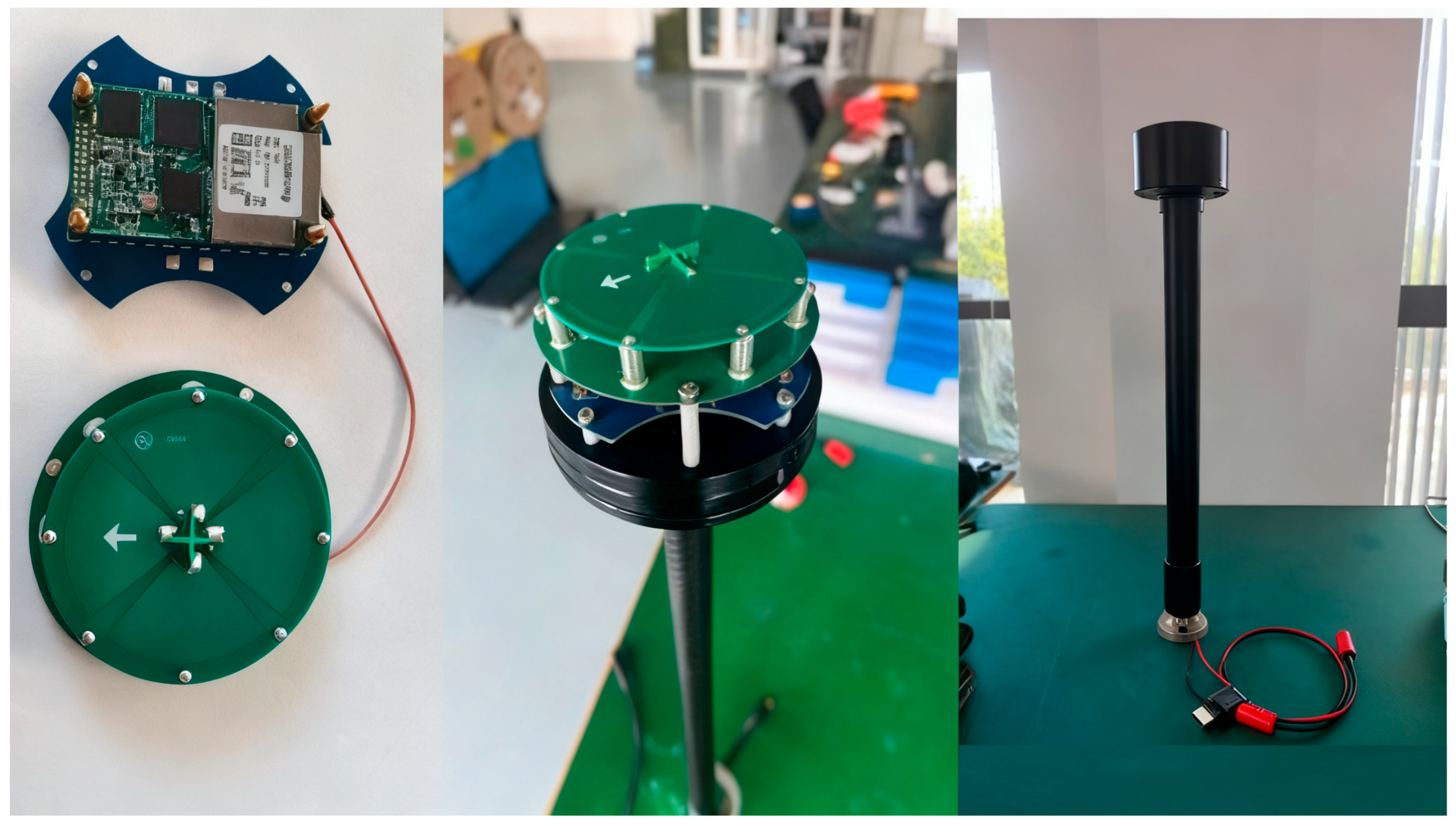
A GNSS integrated unit is installed on the surface float of the wave glider, providing stable and accurate positioning for its marine operations. Based on the P20 board and supporting PPP (Precise Point Positioning) single-point positioning, a high-precision GNSS integrated unit with built-in IMU for RTK-PPP high-accuracy positioning was developed, as shown in Figure 2.
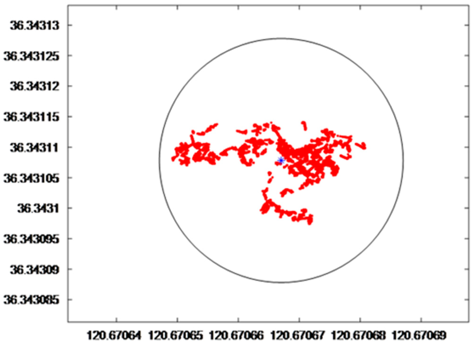
From 09:00 on 12 August 2024, to 00:00 on 13 August 2024, a total of 23 h of data collection were conducted, produced 83,203 data points. The probability of measurements falling within a 2 m radius error circle was 100%. The scatter plot of the positioning accuracy test is shown in Figure 3. However, under complex sea conditions, potential failure modes should also be considered, such as temporary signal loss caused by sea surface reflection or multipath interference, signal attenuation under heavy rain or thick cloud cover, and antenna blockage or position drift induced by wave-driven attitude changes. To mitigate these effects, the system can employ multi-constellation and multi-frequency reception, optimize antenna placement and ground reference, and implement GNSS/IMU tightly coupled integration with RAIM integrity monitoring for anomaly detection and exclusion. When GNSS performance degrades, short-term dead-reckoning based on inertial and velocity constraints can be activated, and RTK/PPP differential correction can be applied when available to restore positioning accuracy, thereby enhancing continuity and reliability under extreme sea conditions.

2.3. SeaSPY2 Magnetometer Towed Body

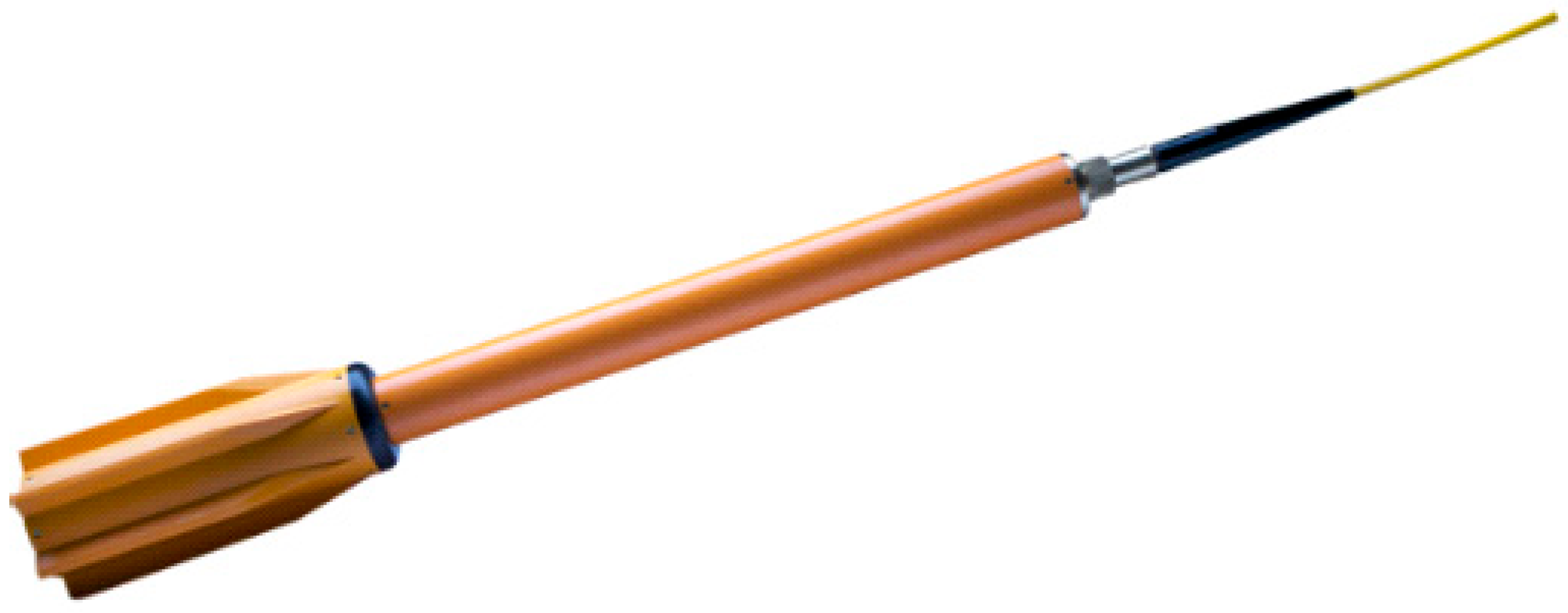
The SeaSPY2 magnetometer towed body, as a high-performance marine magnetic survey device, features an integrated design and high-precision magnetic measurement capability, making it a core instrument for marine geophysical exploration, underwater target detection, and oceanographic research. It adopts a streamlined hydrodynamic design, minimizing towing resistance, and can be deployed from survey vessels of varying tonnage. Adjusting the towing cable length allows surveys at different depths and reduces vessel-induced interference on the measurement, as shown in Figure 4.
The performance parameters of SeaSPY2 are shown in Table 2. Considering the combined requirements of high precision, deep-water capability, and low hydrodynamic drag, the SeaSPY2 demonstrates superior overall performance and reliability, making it the preferred choice for the present research.
In addition, it features excellent high-pressure resistance and corrosion resistance, allowing it to operate continuously for extended periods in complex marine environments. This ensures stable and efficient acquisition of marine magnetic data. Particularly in offshore unmanned magnetic surveys, it can be integrated with platforms such as wave gliders to form a “positioning–detection–data transmission” operational system, significantly expanding the operational range and application scenarios of marine magnetic measurements.

3. Engineering Design of a Wave Glider-Based Magnetic Survey System

3.1. Modification of the Magnetometer Towed Body

Since the wave glider is driven by wave energy, the platform itself is greatly affected by wave conditions. During magnetic surveying, large attitude fluctuations of the sensor can compromise the quality of magnetic data. To ensure the stability of the magnetometer towed body, two approaches were adopted: one involved modification to the towed body itself, and the other focused on the design of the towing cable connecting the wave glider to the towed body.
However, the inherent limitation of this system lies in its relatively low towing speed (generally below 1.0 m/s), which restricts survey efficiency and increases the platform’s sensitivity to surface wave disturbances. This constraint must be considered when conducting long-distance or high-resolution magnetic surveys.
Generally speaking, it is necessary to ensure the stability of the magnetometer towed body during its movement, with the pitch angle range controlled at approximately ±5°. Therefore, we have made modifications in three aspects. First, neutral buoyancy adjustment was carried out. Second, restoring moments were introduced to improve attitude stability. Third, a state monitoring system was integrated, including depth, heading, pitch, and roll measurements. Depth monitoring was used to eliminate vertical gradients, heading data supported heading compensation, while pitch and roll measurements enabled real-time attitude monitoring. Although the magnetometer measures a scalar field, the roll, pitch, and yaw of the towed body are continuously monitored to assess the stability of the towing system. Maintaining stable platform motion ensures that the magnetic measurements are minimally affected by mechanical disturbances.
To ensure the reliability of the magnetometer for subsequent sea trials, it was calibrated at the Metrology Center before the experiment. At a sampling rate of 1 Hz, the calibration results indicated that under standard magnetic fields of 50,472.1 nT, 60,377.2 nT, 70,358.0 nT, and 80,342.0 nT, the indication errors of the magnetometer were 2.9 nT, 2.5 nT, 3.4 nT, and 5.2 nT, respectively, with a measurement uncertainty (k = 2) of 0.8 nT. Additionally, the peak noise was 0.07 nT (measurement uncertainty, k = 2: 0.01 nT), and the time drift within 0.5 h was 0.03 nT (measurement uncertainty, k = 2: 0.01 nT, calculated by moving average of 1 min data for 60 times). These precise calibration metrics validate the magnetometer’s performance for the subsequent sea trial application.
To obtain high-precision attitude data for positioning error correction and dynamic attitude optimization of the GNSS module, the HEC366 High-Precision Full-Attitude 3D Electronic Compass (Manufacturer: Wuxi Witlink Information Technology Co., Ltd.) was adopted. This device integrates a three-axis fluxgate (for heading calculation), a three-axis accelerometer (for tilt compensation), and magnetic interference compensation functions, enabling full-attitude measurement (heading: 0–360°, pitch: ±90°, roll: ±180°) with excellent accuracy—0.2° (RMS) heading accuracy under horizontal use (uniform magnetic field), 0.05° pitch accuracy, and 0.1° roll accuracy. The calibrated attitude data (pitch, roll, heading) from this device directly supported subsequent positioning error correction and dynamic attitude deviation adjustment of the GNSS positioning module.
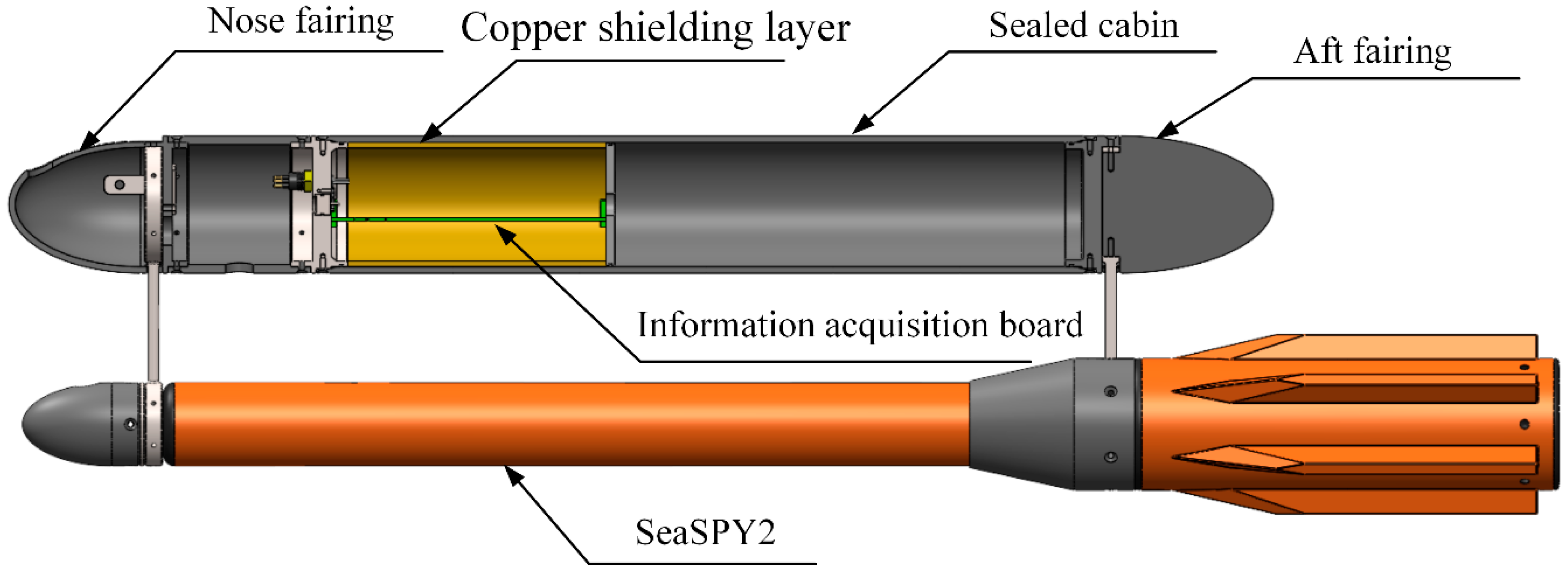
A dual-backup acquisition scheme recorded data on both the towed body and the wave glider. A stabilizing cabin was added to the upper section of the towed body. On the one hand, this cabin increased the distance between the center of gravity and the center of buoyancy, thereby improving stability; on the other hand, it provided space to integrate additional sensors, such as a depth sensor and a data acquisition circuit. To minimize external electromagnetic interference, the IMU circuit board was enclosed in a copper shielding layer, which effectively isolates the magnetic sensor from onboard electronics while maintaining the normal operation of the internal circuitry. The modified towed body is shown in Figure 5.

3.2. Towing Cable Shock Absorption and Disturbance Mitigation Design

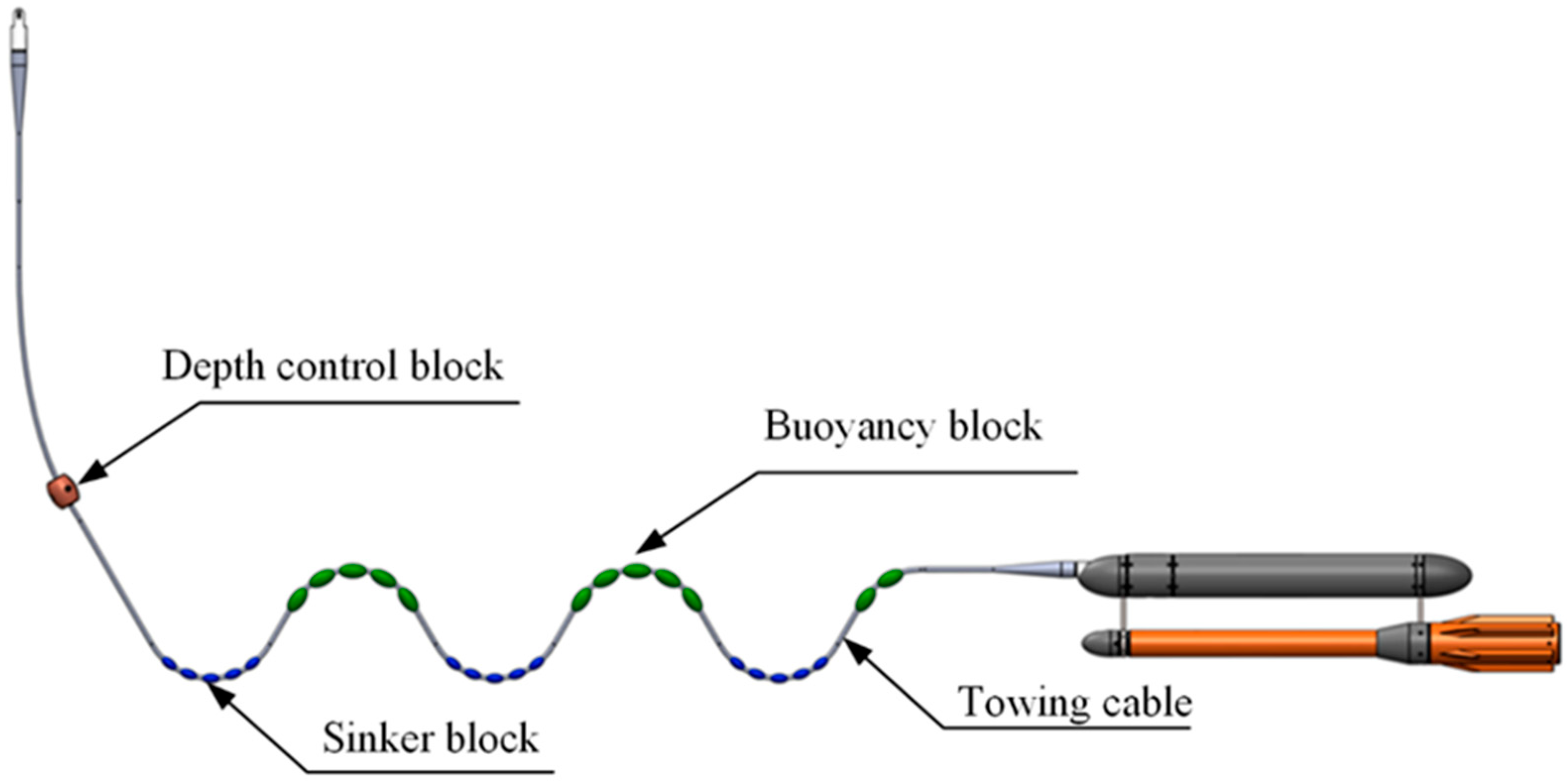
To mitigate the motion interference of the wave glider on the towed body during navigation and enhance the stability of the latter, this study introduces an innovative S-shaped towing cable. By precisely configuring counterweights and buoyancy blocks, the towing cable naturally forms an inverted S-shaped profile in the water. This configuration effectively buffers the vertical and horizontal motion disturbances from the glider, reducing the transmission efficiency of such interferences. The specific structural composition is shown in Figure 6.
The S-shaped towing cable contains a combination of sinker blocks and buoyancy blocks. This configuration can be equivalently modeled as a spring–damper system, which helps interpret its dynamic characteristics. The spring effect buffers external forces through elastic deformation, while the damping effect dissipates energy and reduces oscillations. In practice, the inherent elasticity of the cable, together with the hydrodynamic drag of the sinker and buoyancy blocks, dissipates part of the forward kinetic energy of the system, analogous to the damping mechanism.
Therefore, each “sinker block + buoyancy block” assembly can be equivalently modeled as a spring–damper system, where the spring stiffness k , damping coefficient c , and mass m are determined by the buoyancy and weight of the blocks, their drag coefficients, and their masses, as shown in Figure 7.
When the number of segments is two, according to the equivalent principle shown in Figure 7, the equations of the spring–damper system can be expressed as:
m 1 x ¨ 1 + c 1 ( x ˙ 1 x ˙ 2 ) + k 1 ( x 1 x 2 ) = 0 m 2 x ¨ 2 + c 1 ( x ˙ 1 x ˙ 2 ) + k 1 ( x 1 x 2 ) c 2 ( x ˙ 2 x ˙ 3 ) k 2 ( x 2 x 3 ) = 0 m 3 x ¨ 3 + c 2 ( x ˙ 2 x ˙ 3 ) + k 2 ( x 2 x 3 ) c 3 ( x ˙ 3 x ˙ 4 ) k 3 ( x 3 x 4 ) = 0 m 4 x ¨ 4 + c 3 ( x ˙ 3 x ˙ 4 ) + k 3 ( x 3 x 4 ) c 4 ( x ˙ 4 x ˙ 5 ) k 4 ( x 4 x 5 ) = 0 m 5 x ¨ 5 + c 4 ( x ˙ 4 x ˙ 5 ) + k 4 ( x 4 x 5 ) = 0
Therefore, when the number of segments is N, the entire towing cable can be modeled as a series combination of multiple spring–damper systems. By coupling the dynamic equations of each unit, the dynamic system of the whole cable can be established. Solving the motion equations of this system allows the determination of the towing cable’s dynamic response under various sea conditions.
By deeply integrating and technically adapting the wave glider, which possesses autonomous endurance and adaptability to marine environments, the GNSS integrated unit capable of high-precision spatiotemporal positioning, and the underwater towed magnetic detection system that can accurately capture subsurface magnetic anomalies, a towed wave-glider magnetic survey system was successfully developed. This system combines the three core capabilities of “mobile platform + precise positioning + professional detection”, as shown in Figure 8.
The towing cable length is 20 m, which is relatively short and allows the towed magnetometer’s position to be determined with accuracy comparable to conventional vessel-towed systems. Combined with the GNSS positioning of the surface float and the depth and heading measurements of the towed body, the system can reliably track the magnetometer’s position and correct for variations caused by currents or cable movement.
However, it should be noted that the precise positioning of the towed magnetometer remains a challenge due to potential cable deformation and ocean current effects. This limitation will be further optimized in future work. Therefore, when planning survey track lines, a wider coverage range is adopted to account for possible positioning uncertainties.
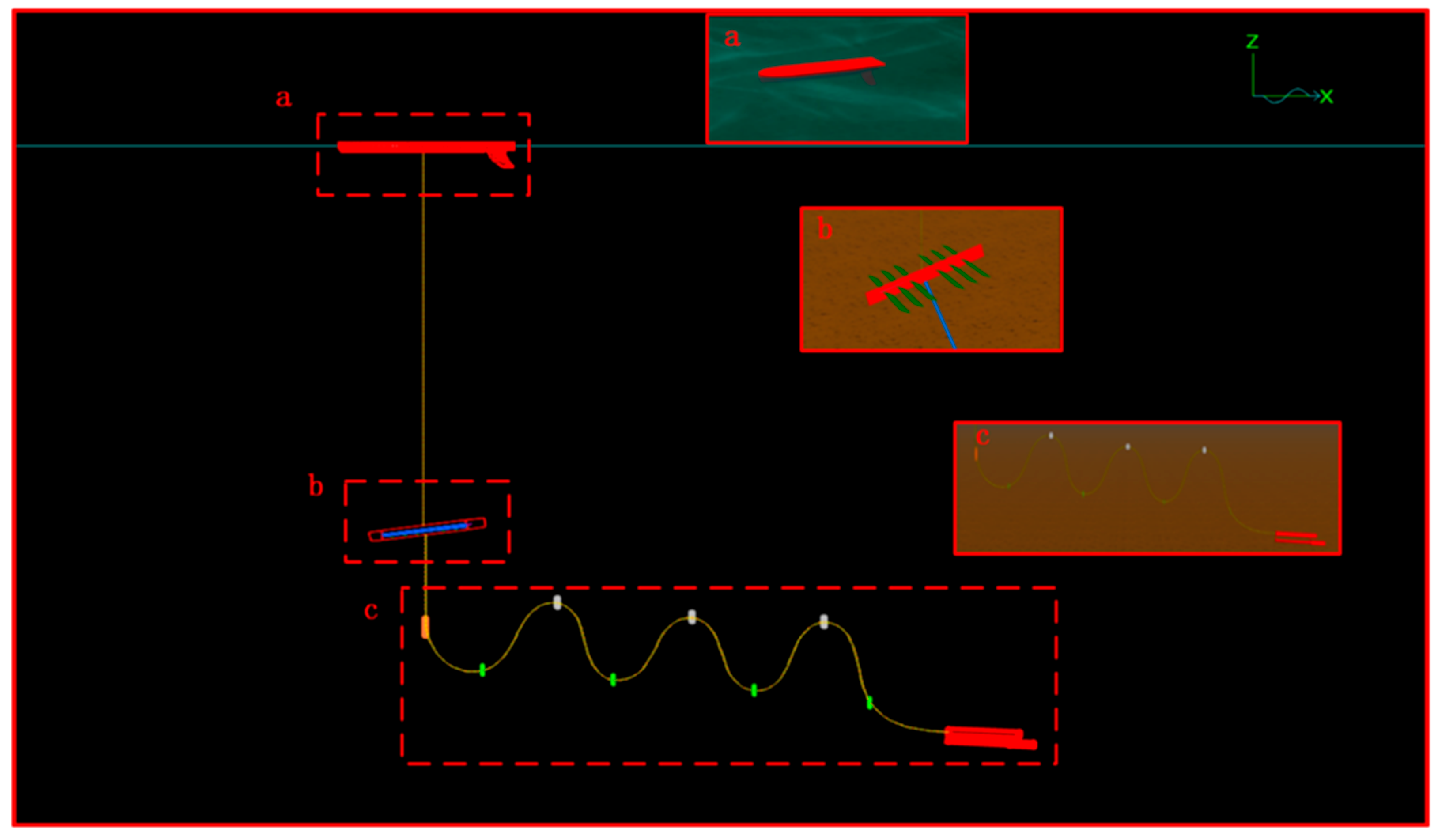
To verify the vibration-damping and disturbance-reducing effects of the S-shaped towing cable on the platform, a 3D simulation model of the wave-glider magnetic survey system was constructed in the hydrodynamic simulation software OrcaFlex11.4, as shown in Figure 9.
The surface float of the wave glider was first analyzed in AQWA to obtain the relevant hydrodynamic coefficients, which were then input into the Vessel module. The umbilical cable was modeled using the Line module with the corresponding structural parameters assigned, while the tandem hydrofoils in the submerged glider were characterized by lift and drag coefficients obtained from Star-CCM+ and input into the 6D Buoy module.
To simulate the actual working environment of the system during marine magnetic survey tasks, this study employed the JONSWAP spectrum (Joint North Sea Wave Project Spectrum), which is widely used in ocean engineering, to construct the wave model. The significant wave height was set to 1.2 m and the wave period to 5 s, corresponding to moderate sea conditions. This parameter combination reflects typical operational scenarios for nearshore and mid-to-far offshore surveys and can effectively evaluate the system’s motion response and operational stability under representative wave conditions.
By comparing the velocities of the wave glider and the towed body, the damping and disturbance-reduction effect of the S-shaped towing cable can be directly illustrated. Figure 10 shows the velocity variations of the wave glider and the towed body under irregular wave conditions. It can be seen that the wave glider exhibits relatively large velocity fluctuations, with instantaneous speeds ranging from −0.5 to 2.0 m/s, displaying pronounced high-frequency, large-amplitude characteristics. This is because the surface float is directly acted upon by the waves and can respond rapidly to the irregular wave excitations.
In contrast, the velocity of the towed body is relatively stable, remaining mostly within the 0.5–0.75 m/s range and exhibiting only low-frequency, small-amplitude fluctuations. This indicates that, during downward transmission through the S-shaped towing cable, the high-frequency components of the waves are effectively filtered out. Consequently, the towed body’s velocity response is smoother, allowing it to maintain a more stable navigation state.
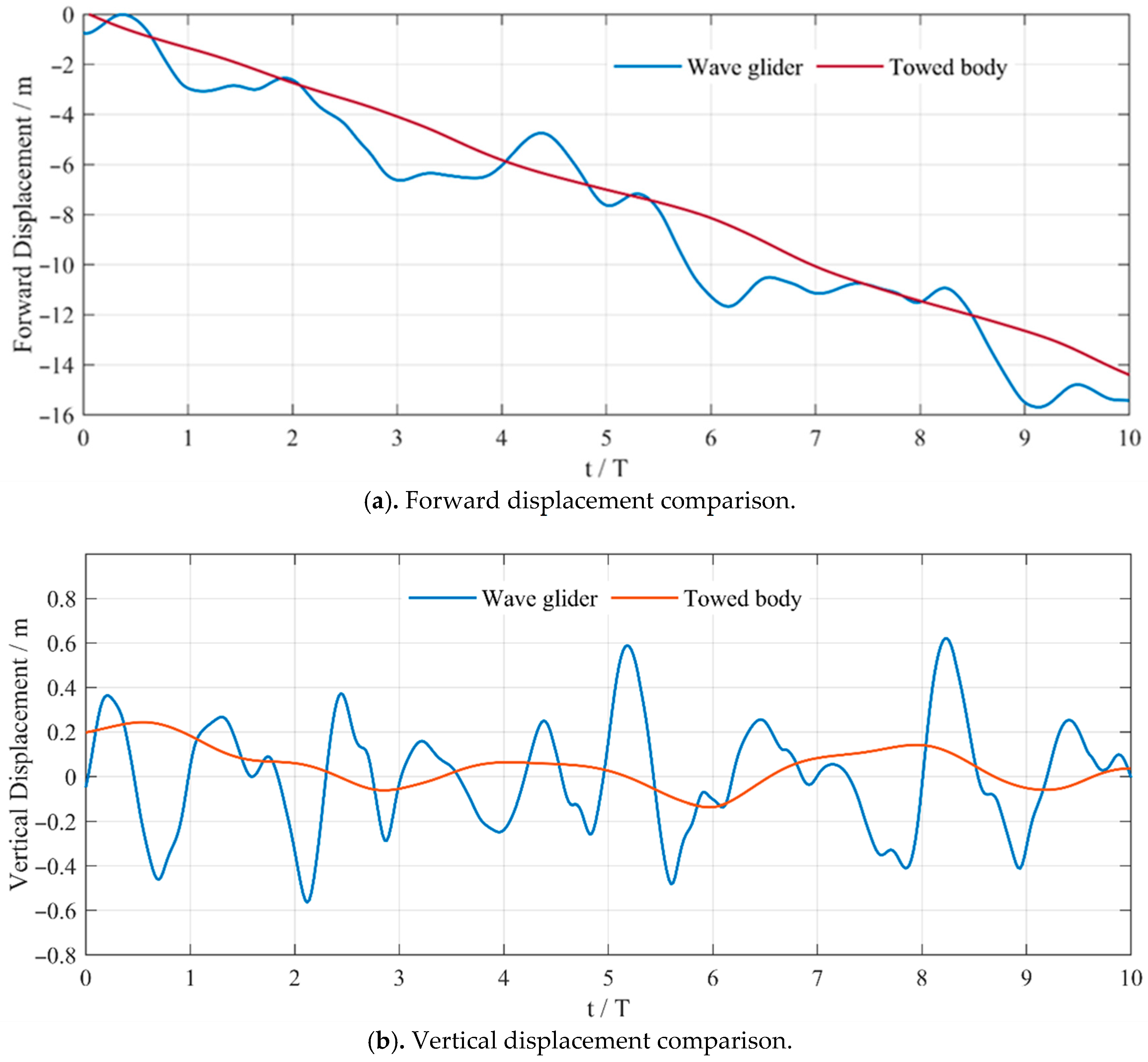
Comparison of displacements between the wave glider and the magnetic towed body, as shown in Figure 11. The wave glider exhibits large fluctuations in forward displacement, whereas the forward displacement of the magnetic towed body shows a monotonically decreasing trend with much smaller fluctuations. The wave glider relies on wave energy to generate forward thrust, resulting in highly variable motion. It responds directly to vertical wave motions, while the vertical movement of the magnetic towed body is significantly attenuated by the S-shaped towing cable. The steady-state motion of the magnetic towed body is more favorable for acquiring continuous and stable magnetic measurements.
Figure 12 shows the variation in the pitch angle of the towed body, with a minimum of −3° and a maximum of 2°, resulting in a range of 5°. It can be seen that the pitch angle of the towed body varies only slightly, further indicating that the S-shaped towing cable effectively filters the vertical motion transmitted from the wave glider.

3.3. Instrument Self-Noise

To evaluate the platform’s magnetic interference and the intrinsic self-noise of the equipment, a self-noise assessment of the modified magnetometer was conducted at the Juxian Seismic Station in Rizhao, and the results were compared with the measurements from the Juxian diurnal variation station, as shown in Figure 13.
The self-noise level was evaluated according to Equations (2)–(4).
S n = 1 n 1 i = 1 n ( B i B ¯ ) 2
B i = T i 2 4 T i 1 + 6 T i 4 T i + 1 + T i + 2 16
B ¯ = 1 n = 1 n B i
where n is the number of observation points included in the calculation, i is the data sequence number, and Sn is the static self-noise of the magnetometer on the ground. The noise level is classified as follows: Level 1: Sn < 0.01 nT; Level 2: 0.01 nT < Sn ≤ 0.03 nT; Level 3: 0.03 nT < Sn ≤ 0.10 nT; Level 4: Sn > 0.10 nT.
The calculation shows that the modified device has a static self-noise of 0.0082 nT, corresponding to a Level 1 rating, meeting the requirements for marine survey applications.
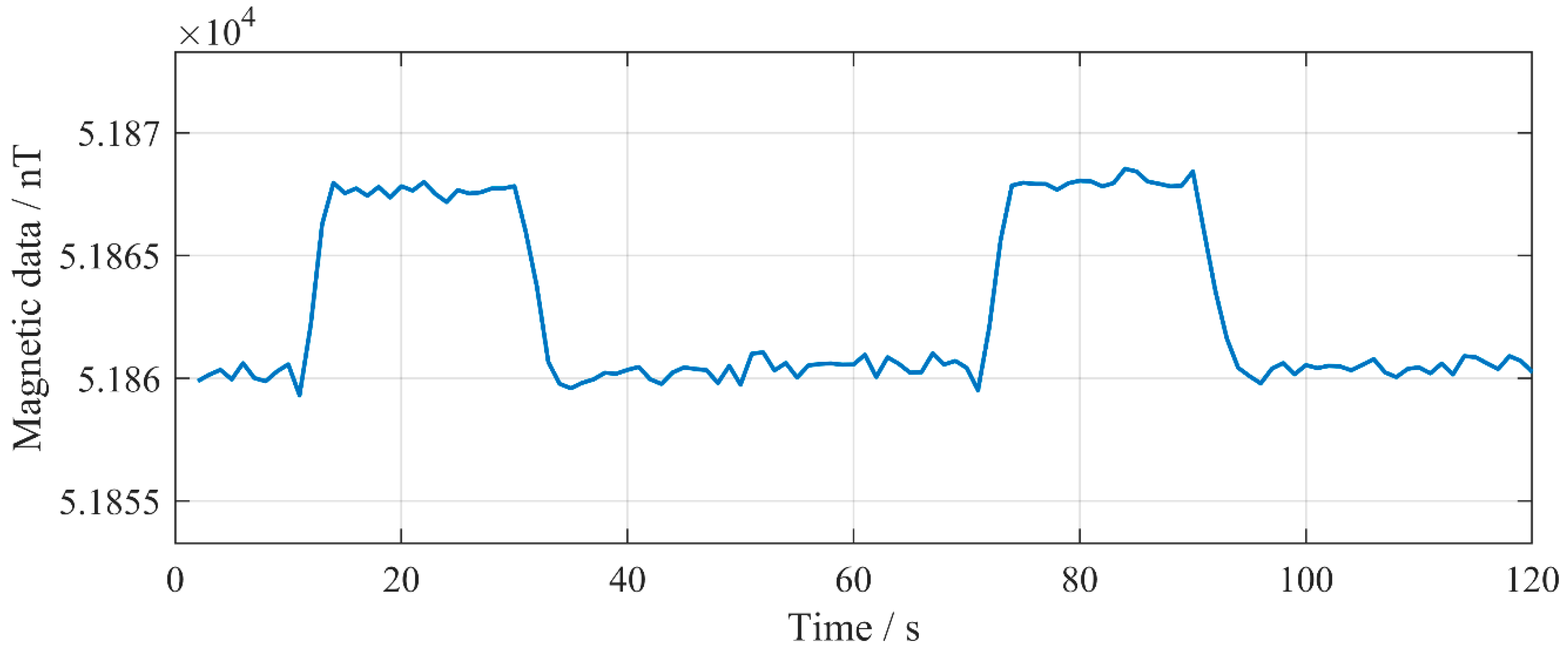
Among the components of the wave glider, only the underwater rudder contains magnetic materials. Therefore, tests were conducted to evaluate the effect of rudder deflection on magnetic survey performance. Specifically, in land experiments, the rudder angle was set within the range of ±30 degrees, the rudder actuation duration was 25 s, and there was an interval between actuations to distinguish the magnetic field state when the rudder was inactive. The results show that the two peaks correspond to changes in the magnetic field during rudder operation, causing an increase of approximately 8 nT, as shown in Figure 14 and Figure 15.
After about 6 m, the towing cable length essentially stabilizes at approximately three times the length of the submerged glider. In addition, the S-shaped towing cable helps minimize the magnetic influence of the rudder. By increasing the separation distance between the magnetometer and the rudder, the extended cable length effectively reduces magnetic field interference generated by the rudder’s motor and metal components. The alternating arrangement of sinker and buoyancy blocks maintains the desired S-shaped profile, which further enhances magnetic isolation and stabilizes the towed body’s motion. As a result, the magnetometer operates in a magnetically stable region, ensuring the accuracy and reliability of the magnetic survey data. The towing cable and power lines were shielded and grounded to further reduce electromagnetic interference (EMI). Therefore, in the actual experiment, the cable length was set to 20 m to ensure data acquisition accuracy.

4. Results and Discussions

4.1. Sea Trial Overview

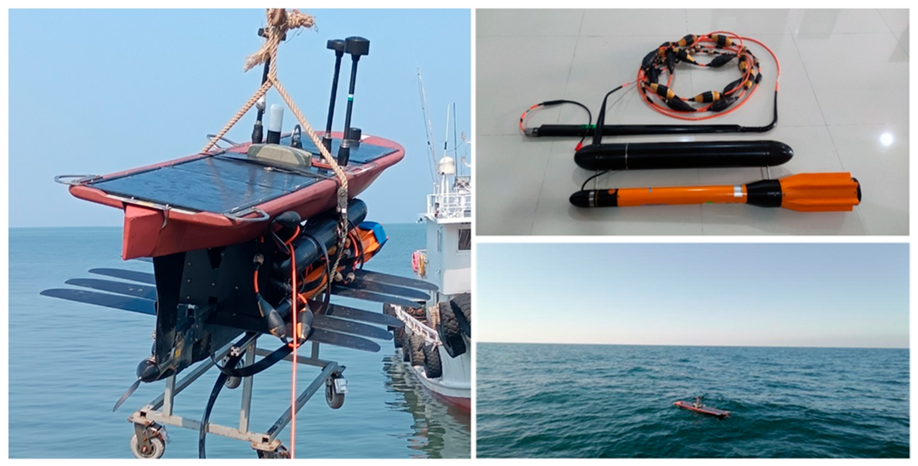
Sea trials of the wave glider magnetic survey system were conducted in the waters near Qingdao. The vessel arrived at point A at 11:00 on 29 August 2024 and began deployment. Repeated survey lines were conducted between points A and B, ending around 17:00 in the afternoon. Subsequently, a zigzag survey was performed around the straight-line connecting points A and B to test the crossing points, continuing until the equipment was recovered around 09:00 on the morning of 30 August, as shown in Figure 16. During the trial, the sea state was moderate, with wave heights of 0.4–0.6 m and a dominant period of approximately 5–6 s. Surface currents were steady at around 0.3 m/s, and wind speeds ranged from 3 to 5 m/s under clear weather conditions. These relatively calm sea and meteorological conditions provided a stable environment for verifying the towing stability and magnetic data quality of the system.
The data were transmitted via the BeiDou system, allowing the onshore monitoring system to observe the operational status of the equipment in real time. High-frequency sampled data were stored onboard the wave glider for subsequent offshore data processing. The navigation track of the equipment and the magnetic anomaly values are shown in Figure 17.
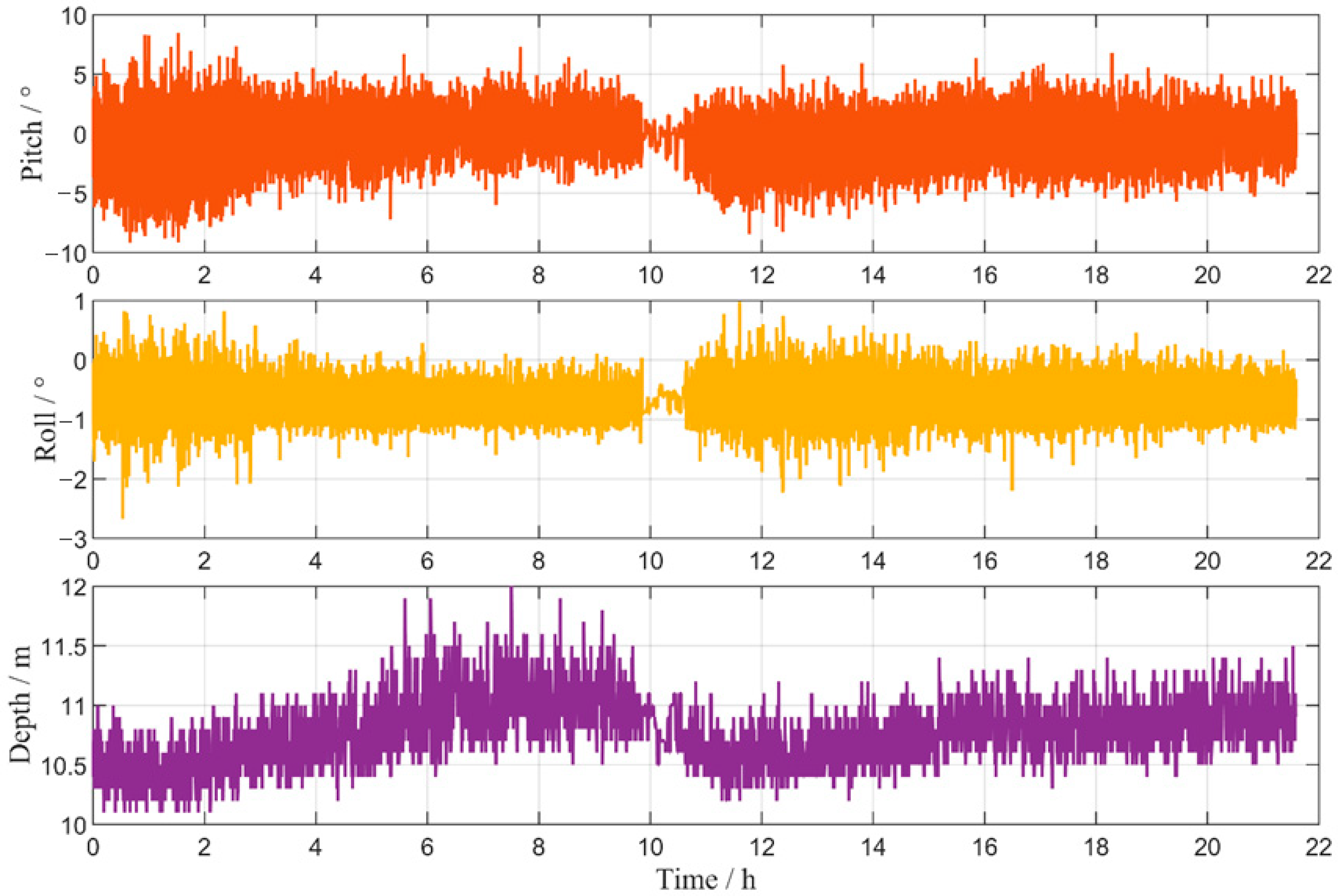
The attitude of the towed body can affect magnetic measurements; therefore, its performance needs to be evaluated. The test results are shown in Figure 18. During the entire sea trial, the towed body operated at a depth of 10–11 m, with pitch maintained within ±5° and roll within ±1°. Overall, under the current sea conditions and cruising speed, the attitude variations of the towed body have no significant impact on the acquisition of magnetic data.
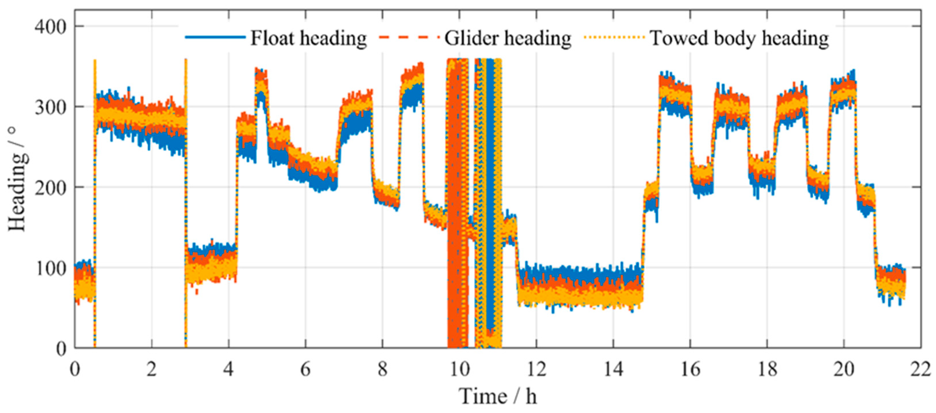
During the experiment, the headings of the surface float, the submerged glider, and the towed body were compared, as shown in Figure 19. The comparison indicates that all three maintained good heading stability during navigation, and the towed body closely followed the platform. This behavior facilitates the accurate determination of the magnetic sensor probe positions in subsequent data processing.

4.2. Diurnal Variation Correction and IGRF Removal

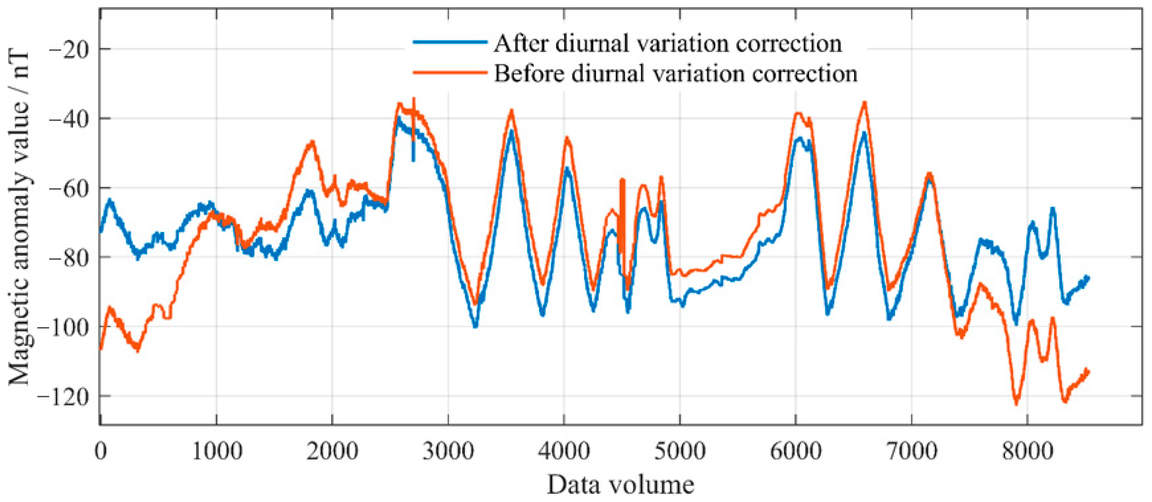
To eliminate the influence of magnetic diurnal variations, diurnal variation correction values were obtained from FHD proton magnetometers at magnetic observatories of the National Geomagnetic Network, Chinese Academy of Geological Sciences, as shown in Figure 20. Meanwhile, the lGRF-13 model (1945–2025) was applied to subtract the normal field [14].

4.3. Dynamic Noise Assessment

The dynamic noise of the experimental data was evaluated using the following formulas [15]:
S i = 1 70 1 n 1 i = 1 n ( B i B ¯ ) 2
B i = T i 2 4 T i 1 + 6 T i 4 T i + 1 + T i + 2
B ¯ = 1 n i = 1 n B i
In the formulas, n denotes the number of measurement points included in the calculation, T i is the i -th magnetic measurement data along the survey line, and B i represents the fourth-order difference of T i , B ¯ is the mean of B i ; S i is the dynamic noise of the magnetometer on the ground. The classification of dynamic noise levels is as follows: Level 1: S i < 0.08 nT; Level 2: 0.08 nT < S i ≤ 0.14 nT; Level 3: 0.14 nT < S i ≤ 0.20 nT; Level 4: S i > 0.20 nT, considered unqualified.
After calculation, the final dynamic noise of the wave glider magnetic survey system was determined to be 0.0639 nT, corresponding to Level 1 dynamic noise. In comparison, the dynamic noise induced by traditional survey ships (i.e., ship noise) is typically higher, generally ranging from 0.1 to 0.5 nT under normal navigation conditions.
Due to the inability to simultaneously acquire conventional vessel-based magnetic survey data during the sea trials, a direct comparison has not yet been conducted. In future research, the Continuous Wavelet Transform (CWT) method will be introduced, together with data from traditional platforms, to enable a more comprehensive multi-frequency noise comparison and analysis.

4.4. Repeat Line Internal Consistency Accuracy Calculation

According to the actual navigation trajectory of the wave glider magnetic survey system, the survey lines were designated as Z1, Z2, and Z3 for the main survey lines, and L1–L18 for the detection lines, as shown in Figure 21.
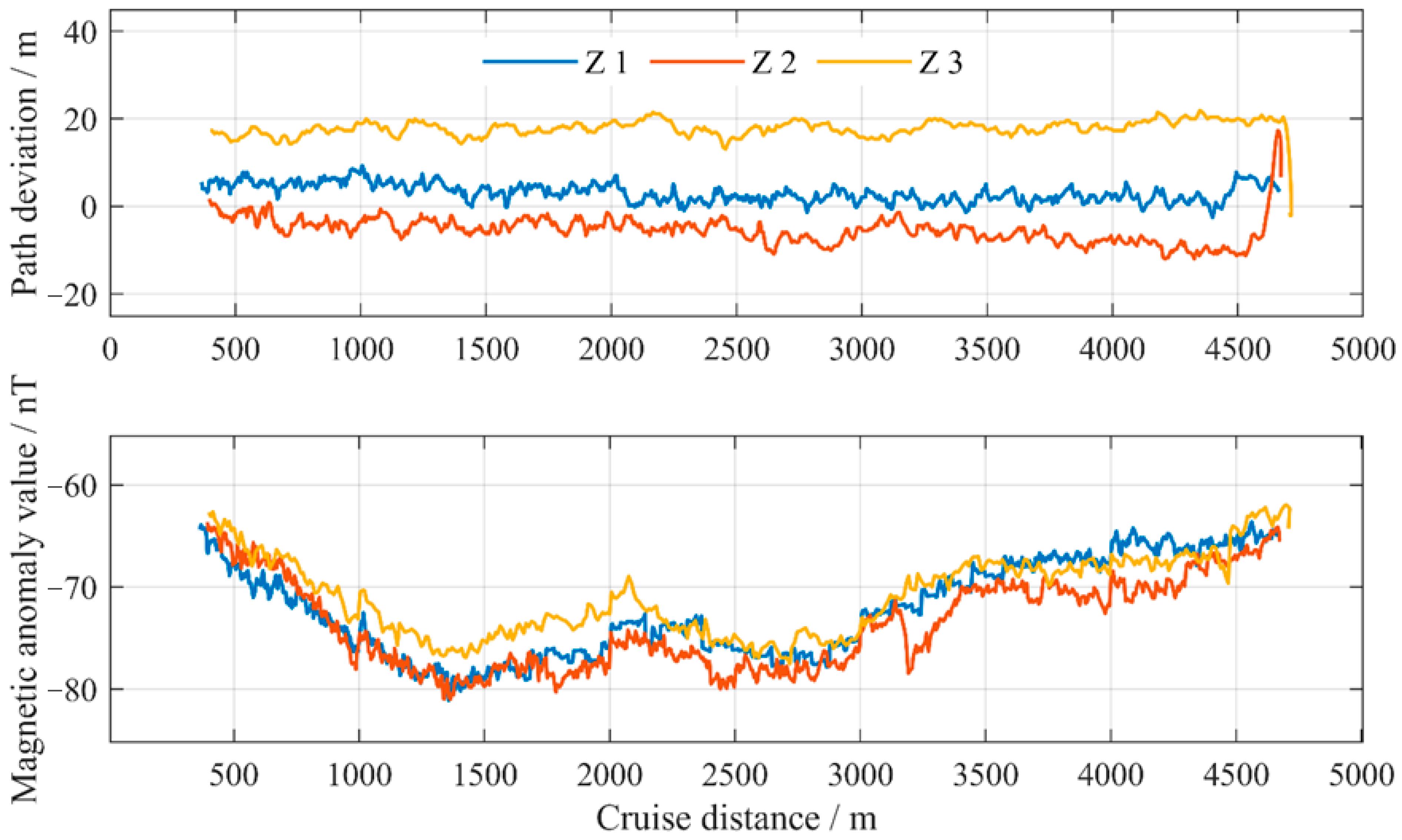
The total survey line length in this experiment was 4.5 km. The AB line, oriented east–west, was traversed three times, and all points along the repeated survey lines fell within a 20 m error range. The enlarged survey path is shown in Figure 22.
This period lasted from 11:00 to 18:00 on 29 August 2024, covering a total distance of approximately 14 km. Due to the influence of current velocity, the trajectory points of the wave glider appeared unevenly distributed. However, the overall navigational speed, accounting for currents, was ~0.56 m/s. The operating speed was generally consistent with the typical performance of the wave glider under seasonal sea conditions.
Due to the course-keeping algorithm, the navigational error of the wave glider was constrained within 50 m. 45 repeated measurements were collected at100 m intervals along a 4.5 km line.
When conducting multiple back-and-forth repeated line measurements, the internal consistency accuracy within the repeated lines is calculated using the following method [16]:
σ = ± j = 1 m ( i = 1 n δ i j 2 ) ( m 1 ) × n j = 1 , 2 , , m ; i = 1 , 2 , n
where σ is the internal consistency accuracy within the repeated lines; m is the number of repeated lines; n is the number of data points on the common segment of the repeated lines; δ i j is the difference between the observed value Fij at the j -th repeated line and the mean value Fi of all repeated lines at the same point.
δ i j = F i j F i j = 1 , 2 , , m ; i = 1 , 2 , n
After analyzing and calculating the magnetic anomaly values, the internal consistency of the repeated lines was determined to be 1.832 nT.
The magnetic anomaly values of the three repeated lines were statistically analyzed, and the results are presented in Table 3.

4.5. Crossing Point Internal Consistency Accuracy Calculation

The internal consistency at crossover points is also an important metric for evaluating the quality of marine magnetic data acquisition. Based on Figure 21, all intersections between the main lines and the check lines were identified, and 46 crossover points were selected for analysis. The criterion for a crossover point was that the distance between two points was less than or equal to 0.5 m. The statistical results of the magnetic field differences at these crossover points are presented in Table 4.
For further analysis of the crossover point data, the distribution of the differences at the crossover points was plotted, as shown in Figure 23. The maximum value is 1.66 nT, the minimum value is −7.47 nT, and the mean value is −1.64 nT.
From the crossover point differences in Table 3, the internal consistency was calculated using Equation (10) as 1.956 nT. This value demonstrates strong internal agreement and falls well within the tolerance range for marine magnetic surveys, which is typically less than 3 nT according to published standards. Therefore, the system meets the accuracy requirements for high-resolution magnetic measurements.
σ = ± i = 1 n δ i 2 2 n i = 1 , 2 , n

5. Conclusions

This study presents the design of a marine magnetometer based on a wave glider platform, evaluates the platform’s intrinsic magnetic noise, conducts nearshore experiments, and completes the accuracy assessment of the wave glider magnetic survey system as well as the overall navigation performance, leading to the following conclusions:
(1) Based on the wave glider’s characteristics and motion patterns, the SeaSPY2 magnetometer was modified and integrated with a high-precision GNSS unit, resulting in an automated marine magnetic survey system suitable for long-duration, wide-area operations in offshore and open-ocean environments.
(2) Through towing cable system design and testing, the magnetometer’s pitch attitude and depth can be effectively controlled. The towed body operates at a depth of 10–11 m, with pitch maintained around ±5° and roll variation within ±1°.
(3) Under nearshore conditions off Qingdao, the system achieves an average navigation speed of 0.56 m/s, with dynamic noise of 0.0639 nT (level 1), demonstrating practical capability for engineering surveys.
(4) The wave glider magnetic survey system maintains a path deviation within 20 m, with internal consistency of 1.832 nT for repeated survey lines and 1.956 nT for cross points, both exceeding the accuracy of conventional research vessel measurements.
The system combines unmanned operation with a low carbon footprint, minimal impact, and long endurance, overcoming the spatiotemporal limitations of conventional shipborne and airborne magnetic surveys and providing an innovative solution for deep-ocean magnetic exploration. In the future, wave-glider-based magnetic survey technology could be further extended to nearshore resource exploration, covert mapping in sensitive areas, and underwater target detection. Coupled with low-cost, clustered deployment, it holds promise for establishing an efficient, wide-area, and sustainable marine magnetic observation network, offering critical technological support for both oceanographic research and commercial applications. In future work, the integration of a fluxgate magnetometer will be considered alongside the scalar magnetometer to enable simultaneous vector and scalar magnetic field measurements. This configuration would not only allow for more comprehensive magnetic data acquisition but also facilitate real-time attitude compensation and improve the overall precision of magnetic field inversion.
Nevertheless, several limitations remain. The low cruising speed limits survey efficiency, and the system’s performance can be affected by strong currents and rough seas. In addition, limited onboard electrical energy constrains the continuous operation of high-power payloads. Future work will aim to improve propulsion efficiency, enhance environmental adaptability, and increase the diversity of magnetometer types for broader and more reliable marine magnetic observations.

Author Contributions

C.L. proposed the original idea and wrote the manuscript. S.M. collected materials and wrote the manuscript. X.S. supervised the manuscript. All authors have read and agreed to the published version of the manuscript.

Funding

This research received no external funding.

Data Availability Statement

The data presented in this study are available on request from the corresponding author.

Acknowledgments

The diurnal variation data used in this study were provided by the National Geomagnetic Network Center of the Institute of Geophysics, China Earthquake Administration. Their FHD proton magnetometer data offered crucial support for diurnal variation correction and the evaluation of magnetic field dynamic noise. In addition, the development of the high-precision GNSS positioning module and the wave glider beacon in this study received technical support from Qingdao Haizhou Technology Co., Ltd., for which we are sincerely grateful.

Conflicts of Interest

The authors declare no conflicts of interest.

References

  1. Engels, M.; Barckhausen, U.; Gee, J.S. A New Towed Marine Vector Magnetometer: Methods and Results from a Central Pacific Cruise. Geophys. J. Int. 2008, 172, 115–129. [Google Scholar] [CrossRef]
  2. Banerjee, B.; Rao, P.B.V.S.; Gupta, G.; Joseph, E.J.; Singh, B.P. Results from a Magnetic Survey and Geomagnetic Depth Sounding in the Post-Eruption Phase of the Barren Island Volcano. Earth Planets Space 1998, 50, 327–338. [Google Scholar] [CrossRef]
  3. De Ritis, R.; Cocchi, L.; Passaro, S.; Chiappini, M. Giant Landslide, Hidden Caldera Structure, Magnetic Anomalies and Tectonics in Southern Tyrrhenian Sea (Italy). Geomorphology 2024, 466, 109445. [Google Scholar] [CrossRef]
  4. Uhm, J.; Jeong, S.; Bang, M.; Yi, M.-J. Joint Interpretation of Aero-Radiometric and Magnetic Survey Data for Ultramafic Rocks in the Yugu Area, South Korea. J. Appl. Geophys. 2025, 241, 105843. [Google Scholar] [CrossRef]
  5. Koyama, T.; Kanda, W.; Utsugi, M.; Kaneko, T.; Ohminato, T.; Watanabe, A.; Tsuji, H.; Nishimoto, T.; Kuvshinov, A.; Honda, Y. Aeromagnetic Survey in Kusatsu-Shirane Volcano, Central Japan, by Using an Unmanned Helicopter. Earth Planets Space 2021, 73, 139. [Google Scholar] [CrossRef]
  6. Shahsavani, H.; Smith, R.S. Aeromagnetic Gradiometry with UAV, a Case Study on Small Iron Ore Deposit. Drone Syst. Appl. 2024, 12, 1–9. [Google Scholar] [CrossRef]
  7. Petersen, J.T.; Døssing, A. Addressing Magnetometer Inconsistencies in Drone-Borne Total Field Gradiometer Surveys: Case Study from Rånbogen, Arctic Norway. Geophys. J. Int. 2024, 239, 1617–1628. [Google Scholar] [CrossRef]
  8. Lipovský, P.; Draganová, K.; Novotňák, J.; Szőke, Z.; Fiľko, M. Indoor Mapping of Magnetic Fields Using UAV Equipped with Fluxgate Magnetometer. Sensors 2021, 21, 4191. [Google Scholar] [CrossRef] [PubMed]
  9. Bronner, A.; Munschy, M.; Sauter, D.; Carlut, J.; Searle, R.; Maineult, A. Deep-Tow 3C Magnetic Measurement: Solutions for Calibration and Interpretation. Geophysics 2013, 78, J15–J23. [Google Scholar] [CrossRef]
  10. Oehler, J.-F.; Schifano, V.; Marquis, G.; Reiller, H.; Lucas, S.; Bougeault, C. Processing of Unmanned Underwater Vehicle Vector Magnetometer Data. Geophys. Prospect. 2024, 72, 2902–2918. [Google Scholar] [CrossRef]
  11. Teixeira, F.C.; Quintas, J.; Pascoal, A. Experimental Validation of Magnetic Navigation of Marine Robotic vehicle. IFAC-PapersOnLine 2016, 49, 273–278. [Google Scholar] [CrossRef]
  12. Jung, J.; Park, J.; Choi, J.; Choi, H.-T. Autonomous Mapping of Underwater Magnetic Fields Using a Surface Vehicle. IEEE Access 2018, 6, 62552–62563. [Google Scholar] [CrossRef]
  13. Choi, S.; Kim, M.; Park, Y.; Moon, G.; Choe, H. Magnetic Data Correction for Fluxgate Magnetometers on a Paramagnetic Unmanned Surface Vehicle: A Comparative Analysis in Marine Surveys. Sensors 2025, 25, 4511. [Google Scholar] [CrossRef] [PubMed]
  14. Alken, P.; Thébault, E.; Beggan, C.D.; Amit, H.; Aubert, J.; Baerenzung, J.; Bondar, T.N.; Brown, W.J.; Califf, S.; Chambodut, A.; et al. International Geomagnetic Reference Field: The Thirteenth Generation. Earth Planets Space 2021, 73, 49. [Google Scholar] [CrossRef]
  15. Laiping, R.; Gengfeng, W.; Zhe, Z.; Yueyuan, M.; Zhongxiao, G. Test and Analysis of Marine Magnetometer Performance. Hydrogr. Surv. Charting 2016, 36, 38–42. [Google Scholar]
  16. Jiangang, L.; Haibing, L.; Jingxiao, L.; Haihu, L.; Cheng, L. FU Bibo Accuracy evaluation of marine magnetic measurement based on small unmanned ship. Hydrogr. Surv. Charting 2022, 42, 25–29. [Google Scholar]
Figure 1. Structural composition and working principle of the wave glider.
Jmse 13 02089 g001
Figure 2. Integrated GNSS module.
Jmse 13 02089 g002
Figure 3. GNSS positioning accuracy test.
Jmse 13 02089 g003
Figure 4. SeaSPY2 magnetometer towed body.
Jmse 13 02089 g004
Figure 5. Modified magnetometer towed body.
Jmse 13 02089 g005
Figure 6. Structural configuration of the S-shaped towing cable.
Jmse 13 02089 g006
Figure 7. Equivalent principle of the S-shaped towing cable.
Jmse 13 02089 g007
Figure 8. Structure of the wave-glider magnetic survey system. (A) underwater geomagnetic towed system (B) overall composition.
Jmse 13 02089 g008
Figure 9. Simulation model of the wave-glider magnetic survey system.
Jmse 13 02089 g009
Figure 10. Comparison of speeds between the wave glider and the magnetic towed body.
Jmse 13 02089 g010
Figure 11. Comparison of displacements between the wave glider and the magnetic towed body.
Jmse 13 02089 g011
Figure 12. Pitch angle of the towed body.
Jmse 13 02089 g012
Figure 13. Comparison between the SeaSPY2 and the Juxian diurnal variation station magnetic field.
Jmse 13 02089 g013
Figure 14. Effect of underwater rudder operation on magnetometer data acquisition.
Jmse 13 02089 g014
Figure 15. Effect of towing cable length on magnetometer data acquisition.
Jmse 13 02089 g015
Figure 16. Sea trials of the wave glider magnetic survey system.
Jmse 13 02089 g016
Figure 17. Navigation track and data acquisition of the wave glider magnetic survey system.
Jmse 13 02089 g017
Figure 18. Comparison of towed body attitude.
Jmse 13 02089 g018
Figure 19. Heading comparison of the wave glider magnetic survey system.
Jmse 13 02089 g019
Figure 20. Diurnal variation correction data before and after adjustment.
Jmse 13 02089 g020
Figure 21. Survey line distribution and designation.
Jmse 13 02089 g021
Figure 22. Accuracy of repeated survey line paths.
Jmse 13 02089 g022
Figure 23. Crossover point difference distribution.
Jmse 13 02089 g023
Table 1. Structural parameters of “Black Pearl” wave glider.
ParametersScaleUnit
Mass of the surface float72kg
Mass of the submerged glider80kg
Total mass of the wave glider152kg
Float dimension2.88 × 0.65 × 0.23m
Submerged glider dimension2.2 × 1.4 × 0.215m
Float maximum displacement270kg
Submerged glider displacement20kg
Length of the umbilical8m
Table 2. Fundamental properties of the SeaSPY2.
Absolute Accuracy0.1 nT
Sensor sensitivity0.01 nT (standard), 0.02 nT (optional)
Counter sensitivity0.001 nT
Resolution0.001 nT
Range18,000 nT–120,000 nT
Gradient ToleranceOver 10,000 nT/m
Sampling range4 Hz–0.1 Hz
CommunicationsRS-232, 9600 bps
Power supply24 VDC
Table 3. Magnetic anomaly values of repeated lines. (unit: nT).
NumberZ1Z2Z3NumberZ1Z2Z3
1−54.4−58.24−54.9424−72.34−73.82−75.72
2−56.17−58.4−55.925−73.74−74.45−75.54
3−56.09−59.04−57.5326−74.57−74.21−76.3
4−57.62−61.13−61.0427−72.64−74.23−76.55
5−59.47−63.1−60.8528−73.35−73.13−74.86
6−60.39−63.94−62.1529−72.12−73.27−73.91
7−62.76−65.51−64.3330−71.51−72.22−73.5
8−64.15−67.63−67.1731−69.95−71.57−77.89
9−66.52−69.7−69.4332−68.72−70.59−74
10−69.55−72.25−72.1133−67.98−70.02−70.29
11−69.79−72.48−73.9534−67.38−68.75−69.85
12−72.07−73.68−74.2635−67.74−66.89−70.05
13−71.75−74.94−74.636−67.93−66.96−71.18
14−70.76−74.25−75.2437−68.52−67.48−70.09
15−69.71−72.69−72.6138−67.61−66.52−71.4
16−69.05−72.37−72.2139−68.7−67.77−71.02
17−68.54−71.99−75.2940−69.28−66.89−72.66
18−68.76−71.75−73.2941−69.79−67.85−72.1
19−68.15−71.39−73.4142−68.2−67.95−69.77
20−68.29−71.22−73.1343−68.06−67.01−68.76
21−70.77−71.51−73.0644−66.22−67.3−69.24
22−71.57−72.33−74.145−64.42−66.41−68.03
23−73.23−73.99−74.99
Table 4. Magnetic field differences at crossover points. (unit: nT).
LineL1L3L5L7L9L11L13L15L7
Z1−3.03−2.51−1.85−3.84−2.87−3.72−7.47−3.39
Z2−7.18−1.59−2.28−4.38−2.93−1.38−3.12−1.780.48
Z3−3.38−1.57−1.54−2.24−1.71−0.63−3.27−2.95
LineL2L4L6L8L10L12L14L16L18
Z1−0.74−2.03−1.36−0.99−5−2.27 −1.97
Z2−3.68−3.7−1.531.16−0.211.66 1.20.92
Z31.38−1.08−1.230.370.82 −0.57
Disclaimer/Publisher’s Note: The statements, opinions and data contained in all publications are solely those of the individual author(s) and contributor(s) and not of MDPI and/or the editor(s). MDPI and/or the editor(s) disclaim responsibility for any injury to people or property resulting from any ideas, methods, instructions or products referred to in the content.