1. Introduction
Ventilated supercavitating vehicles have attracted significant attention from researchers worldwide because of their ability to achieve extremely high underwater speeds. Extensive research has been conducted on model development and control design for these vehicles. However, the mechanical coupling effects among gas-solid-liquid multiphase flows are highly complex, and the underlying mechanisms remain unclear. High-fidelity modeling and robust stabilization control design continue to be core challenges in this field. To date, much work has focused on establishing accurate dynamic models and designing controllers with strong robustness for supercavitating underwater vehicles.
With respect to cavity evolution models, Logvinovich [
1] proposed the cross-sectional independent expansion principle, which provides a theoretical framework for analyzing the effects of the vehicle angle of attack and gravity on the cavity shape. This principle has been extensively validated through experiments and remains the fundamental theoretical basis for accurate cavity prediction to date. Furthermore, Yu. N. Savchenko [
2] experimentally confirmed the validity of the cross-sectional independent expansion principle. Many researchers have subsequently conducted studies on cavity flow patterns and the coupled forces between the cavity and the vehicle on the basis of this principle. In terms of cavity flow pattern prediction, Serebryakov [
3] derived differential equations and boundary conditions for steady and unsteady cavity flows by employing slender body theory and integral conservation laws. Building upon the cross-sectional independent expansion principle and differential equations for steady cavity flows, Y. N. Savchenko [
4] investigated cavity shape by simplifying the steady cavity flow differential equations into algebraic equations. They derived an approximate formula for the drag coefficient of disk cavitators and developed predictive formulas for the length and diameter of axisymmetric cavities at low cavitation numbers. On the other hand, Paryshev [
5] extended the unsteady cavity flow differential equations by incorporating pressure variations and dynamic characteristics within the cavity, employing integral transformations to obtain a sixth-order nonlinear differential equation system describing cavity dynamics.
With respect to the coupled forces between a cavity and vehicle, Paryshev [
5] addressed the interaction by modeling any vehicle cross-section in contact with the cavity as equivalent to a cylinder submerged in a cylindrical water surface. Vasin and Paryshev [
6] on the basis of potential flow theory, incorporated fluid viscosity and surface friction resistance and presented a formula for calculating the steady-state glide force of forward-moving vehicles under conditions of a low wetting ratio and high Froude number. In terms of supercavitating vehicle modeling, [
7] Kirschner et al. [
8] developed a six-degree-of-freedom (6-DOF) model of a supercavitating vehicle and subsequently simplified it. Dzielski and Kurdila [
9] established a two-degree-of-freedom (2-DOF) longitudinal plane model, which, while simplified, retains most typical characteristics of supercavitating vehicles and has become a benchmark model that is widely cited in the literature. Vanek et al. [
10] considered the hysteresis effect between cavity flow patterns and vehicle states, also known as the cavity memory effect, improved the glide force calculation, and developed a time-delay model for supercavitating vehicles.
In recent years, significant efforts have been devoted to improving the modeling of supercavitating vehicles, with numerous numerical and experimental studies addressing various aspects of their hydrodynamics and control. Jiang [
11] experimentally investigated the drag characteristics and flow physics of ventilated supercavitating bodies with different geometries, systematically examining the influence of ventilation rates on drag behavior and analyzing the formation mechanisms and hydrodynamic characteristics of both bubbly and clear supercavities under different Froude numbers. Pham and Ahn et al. [
12,
13,
14] carried out numerical simulations to assess the effects of forebody length, cavitator angle, and control fin sweep angle on supercavity dynamics, providing both qualitative and quantitative insights into cavity shape evolution, hydrodynamic performance, gas leakage mechanisms, and internal pressure distribution under varying vehicle and control surface configurations. Shao [
15] employed high-speed digital inline holography (DIH) to investigate how gas leakage under different cavity closure modes affects the stability of ventilated supercavities, and proposed ventilation control strategies that enhance cavity stability.Despite these advances, early studies on the dynamics and control of supercavitating vehicles were often constrained by computational limitations. As a result, they typically assumed steady vehicle motion and employed simplified cavity evolution models and glide force calculations, which reduced model accuracy and neglected important nonlinear coupling effects. Such simplifications limit the ability to predict vehicle performance under complex maneuvering conditions, highlighting the need for more comprehensive modeling approaches.
In terms of supercavitating vehicle control, Y. Savchenko [
2] analyzed the stability characteristics of vehicles enveloped by cavities and proposed four stable operating modes, laying the groundwork for subsequent control research on supercavitating vehicles. Dzielski and Kurdila [
9] introduced their benchmark model and presented a state feedback control law using only the cavitator rudder angle as the control input, although without extensive explanation. They also suggested controlling the vehicle by simultaneously using both the vehicle’s stern rudder and the cavitator rudder angles as control inputs. Shao et al. [
16], on the basis of a 6-DOF model, categorized the supercavitating vehicle’s dynamics into two states: with and without glide force. Controllers were designed for each state using linear quadratic regulator (LQR) theory, and the switching between control laws was achieved by monitoring the glide depth at the vehicle’s tail. Balas et al. [
17] conducted studies on the benchmark model by transforming it into a bimodal system to confirm controllability. They implemented a twoloop control architecture, where the inner loop employed feedback linearization and the outer loop used dynamic inversion. Although this approach demonstrated satisfactory tracking performance, it imposed impractical demands on the rudder’s capabilities. Building upon Balas’s work, Vanek et al. [
18] introduced a control strategy that combines inner-loop feedback linearization with outer-loop receding horizon control (RHC) for the benchmark model. While this method sacrifices some tracking accuracy, it significantly reduces the rudder performance requirements. Subsequently, Vanek transformed the benchmark model into a linear parameter-varying (LPV) framework and designed controllers accordingly. Lin et al. [
19,
20], on the basis of the benchmark model, designed controllers using robust pole placement methods and applied the circle criterion theorem for nonlinear system analysis. They demonstrated that robust pole placement effectively expands the domain of attraction of the supercavitating vehicle states, thus ensuring system stability; however, actuator saturation occurs as the domain of attraction expands. Sanabria et al. [
21,
22] developed a supercavitating vehicle dynamic model on the basis of experimental data and designed controllers using a mixed sensitivity approach, incorporating control strategies to avoid the generation of glide forces. Zou Wang and colleagues Zou et al. [
23,
24,
25,
26], on the basis of Logvinovich’s cavity cross-sectional independent expansion principle, studied cavity dynamics and established an unsteady ventilated supercavity model. They also investigated the ballistics, guidance, and control of supercavitating vehicles on the basis of the coupled model of unsteady ventilated supercavities and the vehicle. Sun Mingwei et al. Sun et al. [
27] divided the benchmark model into inner and outer loops according to variable rates of change and used the circle criterion theorem to guarantee the absolute stability of the inner loop.
In summary, most control-oriented ventilated supercavity motion models focus on 2-DOF systems, assume steady cavity evolution, overlooks the influence of variations in vehicle motion, and thus weaken the coupling between heterogeneous control channels.
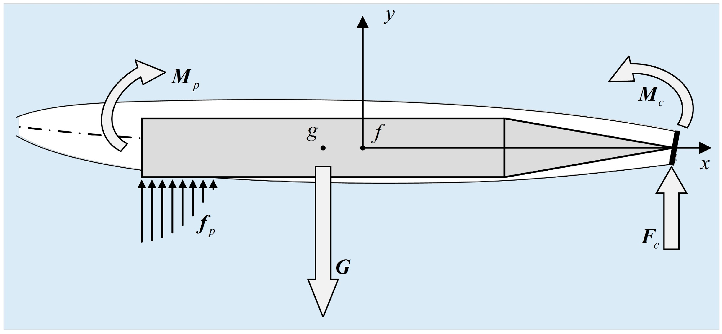
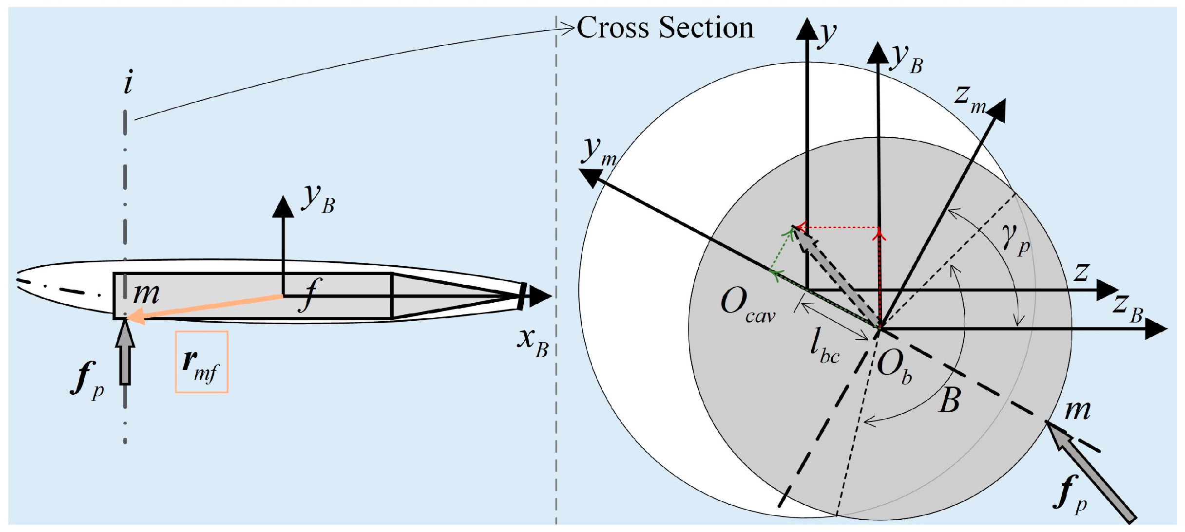
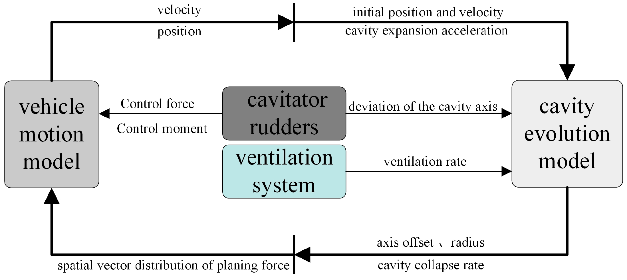
On the basis of the principle of cross-sectional independent cavity expansion, this study introduces an unsteady evolution model for ventilated cavities by spatially discretizing the cavity into multiple slices. The cavity evolution at each slice is computed according to local environmental and motion parameters, thereby completing the coupling relationships among heterogeneous channels. For each slice, the immersion relationship between the vehicle and the cavity cross-section is analyzed. Using the spatial distribution of glide forces derived from [
5], the total glide force and moment are obtained through integration. Combined with the vehicle’s dynamics, a 6-DOF heterogeneous coupled motion model of the ventilated supercavitating vehicle is developed.
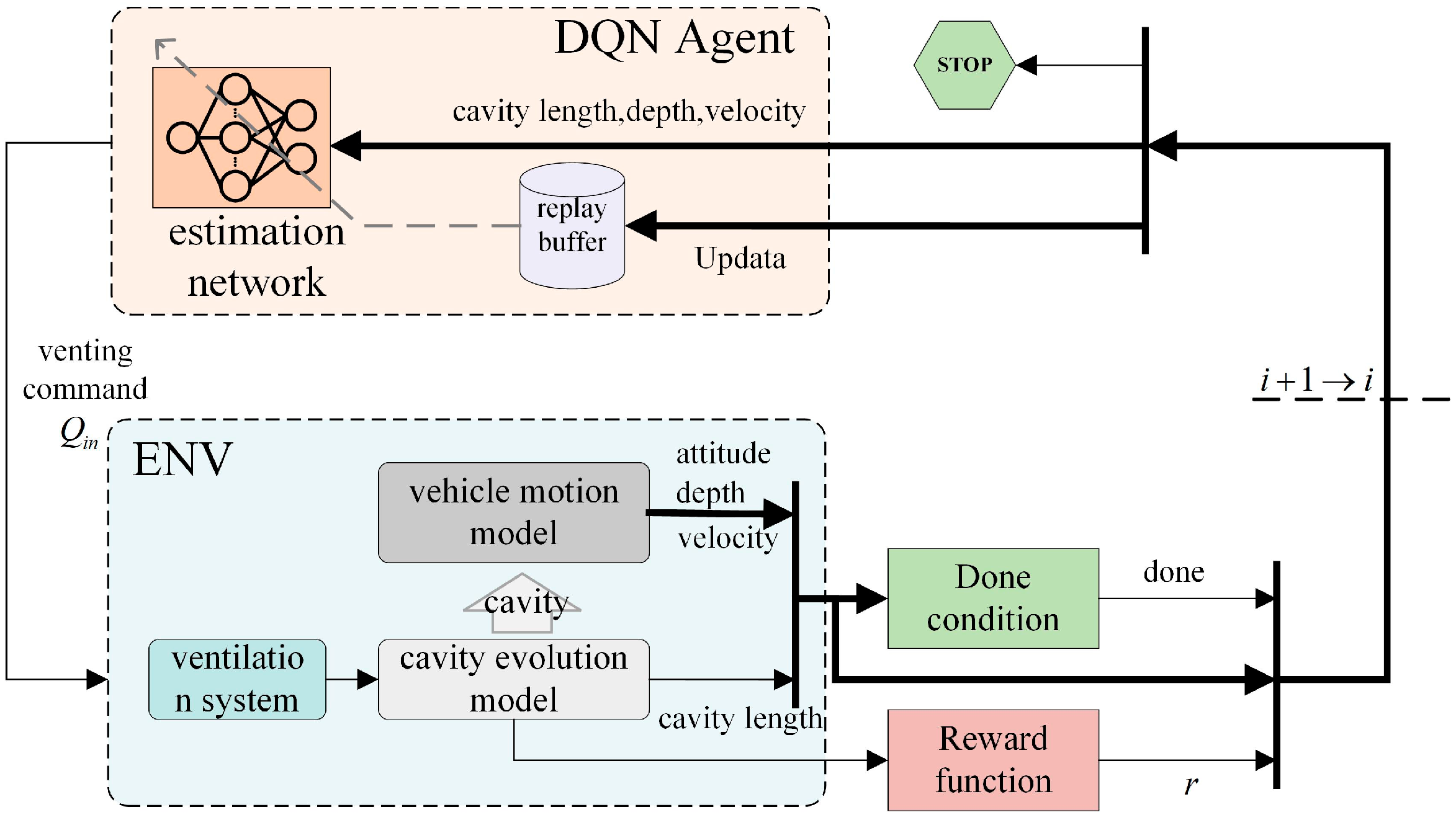
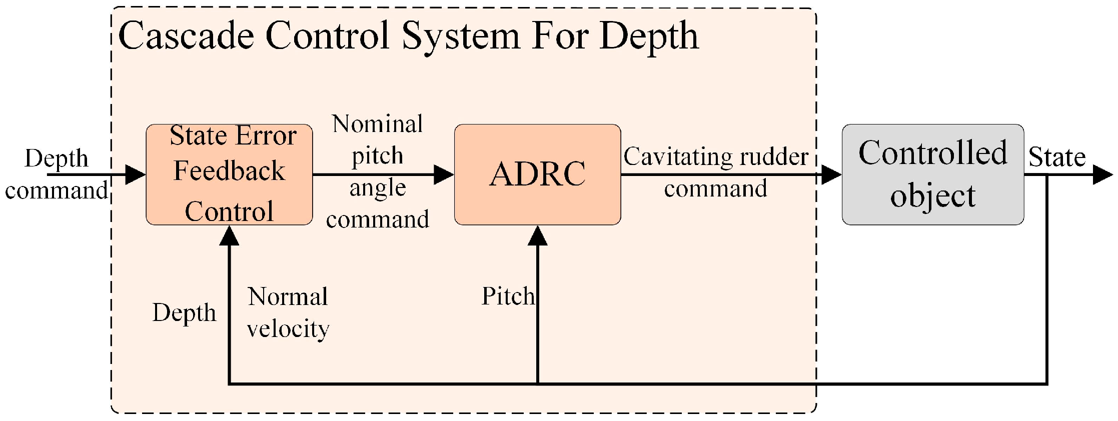
Building upon this model and addressing the coupling effects of heterogeneous channels, a control framework integrating ventilated cavity loop reinforcement learning and cavitator rudder-motion loop active disturbance rejection control (ADRC) is proposed. A deep Q-network (DQN) algorithm is employed to train an intelligent cavity length controller under staged ventilation conditions, effectively maintaining the cavity length during depth variation maneuvers. Moreover, ADRC is used to achieve effective observation and dynamic compensation of the overall disturbance, including glide forces, realizing decoupled control of the pitch channel. This approach is supported by outer-loop error feedback control to achieve accurate depth tracking.
5. Simulation Analysis and Validation
5.1. Simulation Setup
The initial position of the vehicle in the launch coordinate system is set to [0,0,0] m, and its initial velocity in the body-fixed frame is set to [70,0,0] m/s. The depth command is set to −5 m. The vehicle mass is 7.599 kg, the main moment of inertia is [1.0,2.058,2.058] kg·m2, the diameter is 0.1 m, the length is 0.8 m, the cavitator diameter is 0.035 m, and the drag coefficient is 0.82. The ambient vapor pressure is set to 2450 pa, and the surface water pressure is 101,000 pa. The initial simulation depth and velocity are set to 0 m and 70 m/s, respectively.
The simulations were performed using a fixed-step, fourth-order Runge–Kutta integration scheme to solve the coupled differential equations governing vehicle motion and cavity evolution. The time step was set to 0.0001 s to ensure numerical stability and accuracy. Boundary effects and wave-induced disturbances were neglected to focus on the intrinsic dynamics of vehicle–cavity interactions.
5.2. Parametric Study of Cavity Evolution
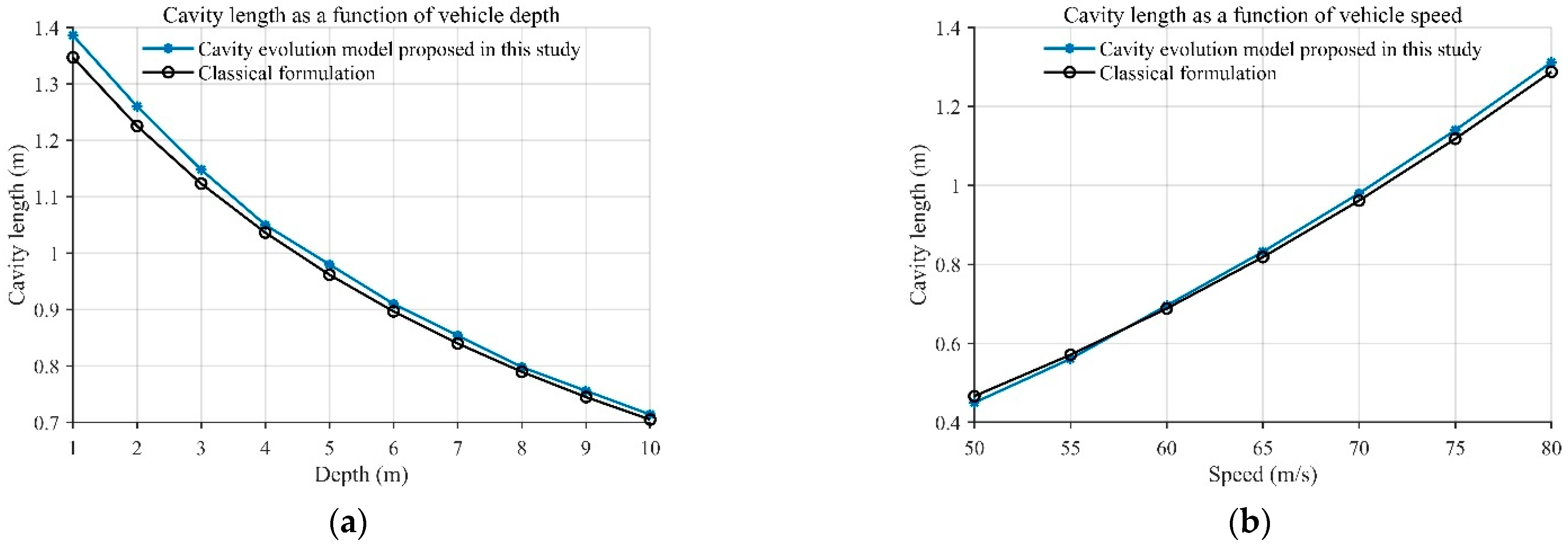
The cavity size plays a crucial role in governing the coupling between the vehicle and the cavity. To validate the effectiveness of the proposed cavity evolution model, a sensitivity analysis of cavity length was conducted and compared with a typical empirical correlation [
4]. The results in
Figure 10 indicate that the cavity length decreases with increasing operating depth and increases with increasing velocity. The observed trends are consistent with the empirical formula, thereby confirming the reliability of the proposed model.
5.3. Simulation Under Uncontrolled Conditions
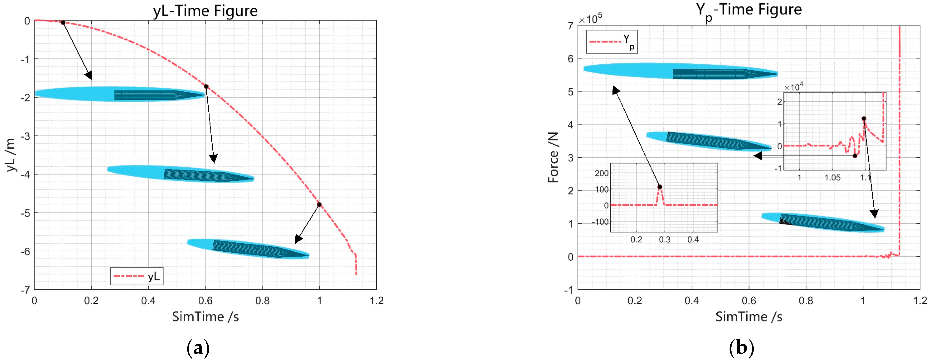
A 6-DOF simulation under uncontrolled conditions was conducted on the basis of the heterogeneous coupled motion model of the ventilated supercavitating vehicle. As shown in
Figure 11, during the initial uncontrolled phase, the vehicle is not yet submerged and is subjected only to gravity: the pitch angular velocity remains zero, and the vehicle’s attitude is maintained; the velocity angle of attack decreases while the cavity axis gradually tilts upward; and the increasing depth leads to higher external pressure, causing the cavity length to shorten progressively. When the cavity contracts and the upward-tilted axis contacts the vehicle’s stern, there is a small positive normal slippage force and corresponding nose-down moment. The negative angular velocity lacks sufficient moment to be eliminated, resulting in the stern gradually pitching upward until submersion occurs and leading to a negative normal slippage force and a nose-up moment. This process introduces a periodic oscillation trend in both the vehicle’s attitude and normal velocity. As the cavity continues to contract and the vehicle submerges further, the amplitude of the slippage forces increases, ultimately leading to divergent motion of the vehicle.
To achieve stable motion and control of the ventilated supercavitating vehicle and in response to the divergence observed in uncontrolled simulations, a control strategy separating cavity length and attitude was developed. In the ventilation–cavity loop, a cavity length controller based on the DQN algorithm was designed to maintain the supercavitating state while preserving favorable characteristics of the slippage force, thereby alleviating the burden on attitude control. In the cavitator rudder–motion loop, a decoupled attitude controller based on ADRC was implemented to dynamically compensate for the “total disturbance,” including slippage forces, enabling precise attitude tracking.
5.4. Training of the Ventilation–Cavity Loop Controller
During training of the cavity-length control loop, the vehicle depth controller was assumed ideal. Each episode corresponded to maintaining cavity length during a simplified motion with constant forward speed and uniform depth change. To improve generalization, the initial vehicle depth, forward speed, and depth-change rate were randomly sampled within specified ranges for each episode.
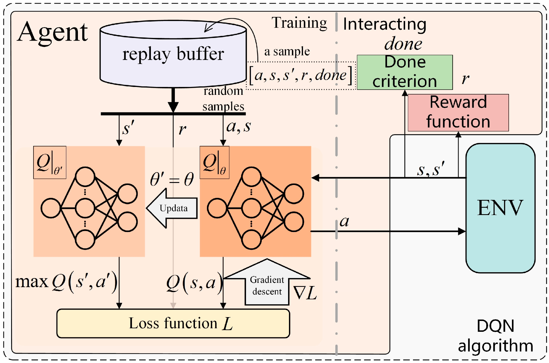
The estimation networks and target networks share the same architecture, consisting of an input layer with dimension , two hidden layers each with dimension , and an output layer of dimension . The training was implemented in Python 3.10 using the PyTorch 2.8 framework, with the Adam optimizer and a learning rate of 0.001. The experience replay buffer had a capacity of 10,000 transitions, and the mini-batch size was set to 64. Training was conducted over 1000 episodes, with a reward discount factor of 0.1. The vehicle’s initial depth was randomly sampled within 0–20 m, the forward speed ranged from 55 to 85 m/s, and the depth-change rate varied between −2 and 2 m/s, allowing the controller to learn robust cavity-length regulation across a wide range of operating conditions. To ensure training stability, the target network was updated using a fixed-step soft update strategy (τ = 0.01), and the observed states were normalized prior to being fed into the network to accelerate convergence.
On the basis of the designed reward and termination functions, the maximum reward per step is determined to be
, resulting in a maximum cumulative reward of
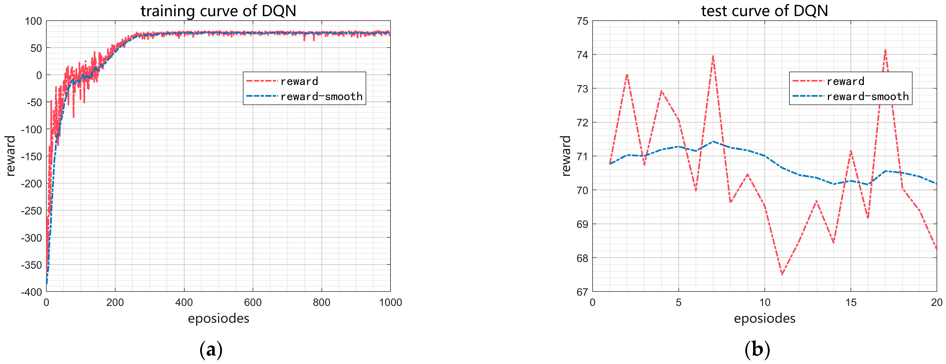
per episode. As shown in
Figure 12, after 1000 training episodes, the agent’s reward stabilizes at approximately 74. During subsequent testing over 20 episodes, the average episode reward remains near 70, with a maximum of 74 and a minimum of 67. These results demonstrate that the reinforcement learning-based cavitation length controller exhibits strong stability and effective control performance.
During training, the vehicle’s speed was kept constant, and its depth varied uniformly. However, real-world operating conditions are typically much more complex. To further evaluate the robustness and generalization capability of the trained model, simulation experiments were designed in which both the vehicle’s speed and depth vary sinusoidally, in order to examine the DQN controller’s performance in maintaining the cavity length under more realistic conditions. The variation profiles of vehicle speed and ambient pressure are given in Equation (59). In these simulations, the trained DQN cavity length controller was used to maintain a cavity length of 1.8 m. As shown in
Figure 13, the cavity length is maintained at approximately 1.8 m, with a maximum deviation of less than 0.1 m. These results demonstrate that the model can effectively handle moderate disturbances in vehicle speed and depth, maintaining a stable cavity length.
5.5. Control Design for the Cavitator Rudder–Motion Loop
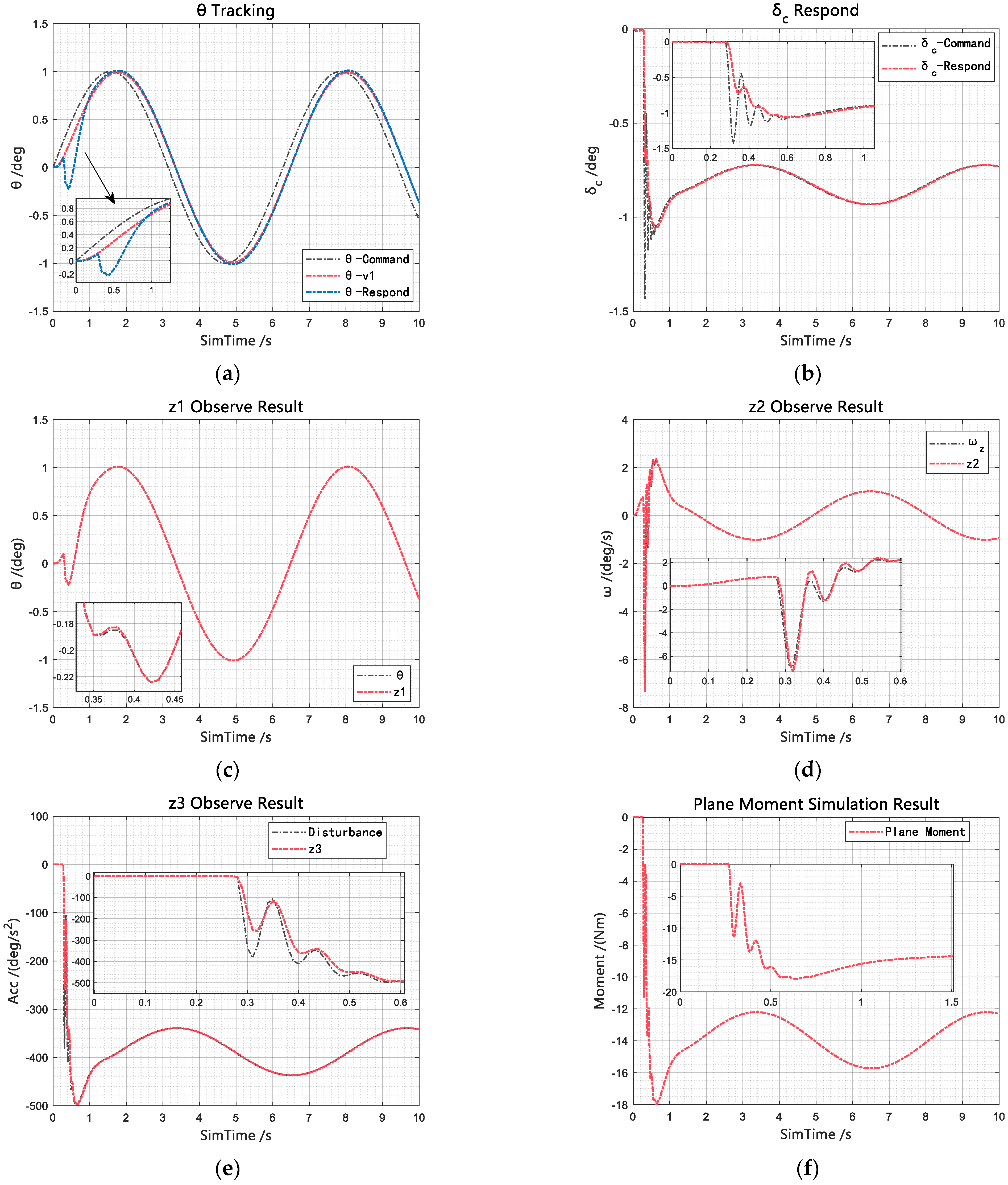
Assuming a constant cavity shape, the ADRC is designed on the basis of the simplified dynamic model given in (34). The design parameters are selected as follows: the fast convergence factor is set to 10, and the observer parameters are chosen as , , and . The control gain is set to , and the control law parameters are configured as , . A sinusoidal pitch angle command is applied to evaluate the tracking performance.
As shown in
Figure 14, the ESO effectively estimates the current pitch angle
, pitch rate
, and total disturbance
. By incorporating the estimated states into the state error feedback control law, dynamic compensation-based linearization is achieved. The resulting system exhibits characteristics of a second-order cascaded integrator. Under the action of simply tuned control parameters, the pitch angle leads to satisfactory tracking performance.
The outer-loop error feedback controller is designed with the parameters set as
,
, and
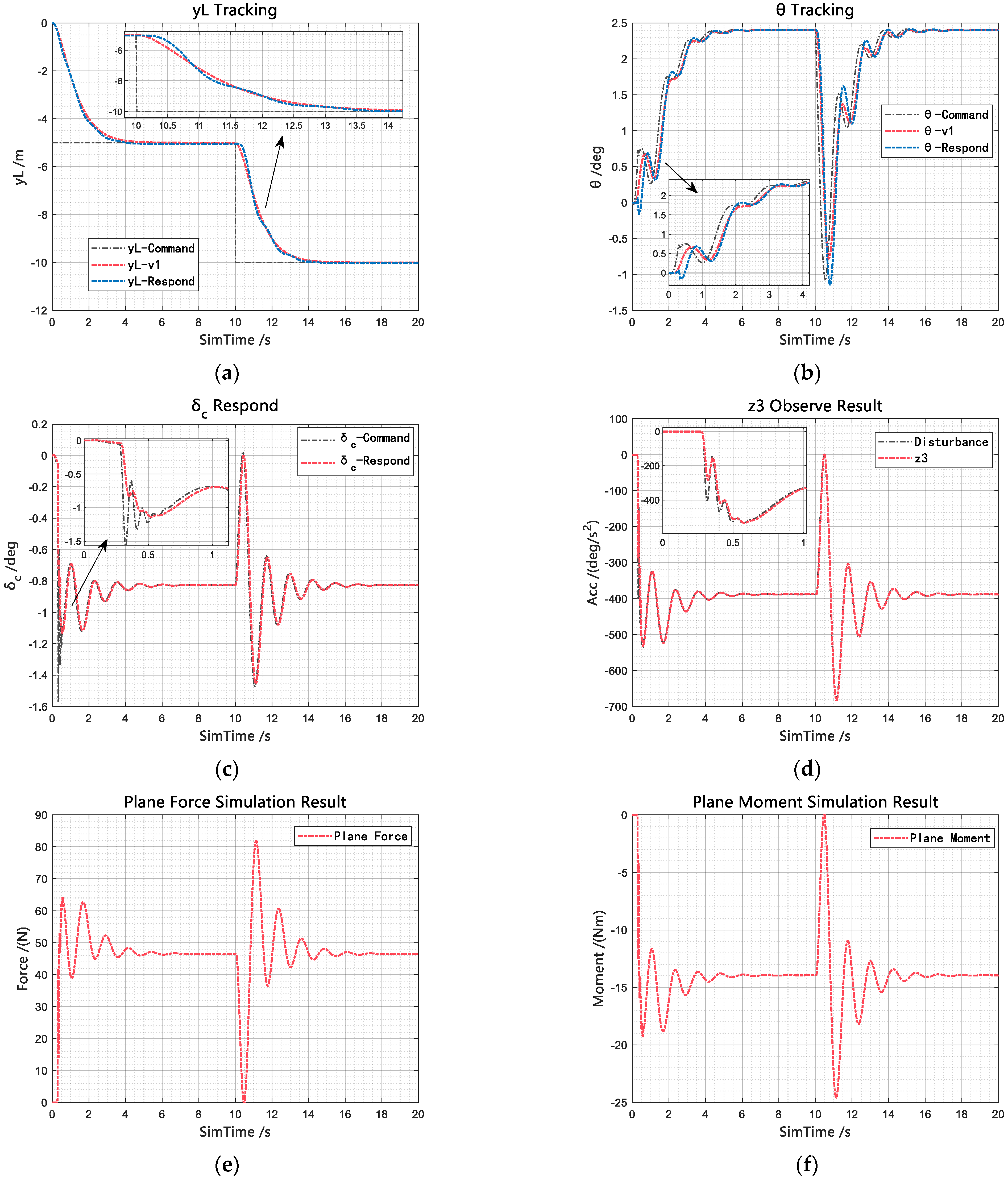
. The simulation results for the depth variation control are shown in
Figure 15.
As shown in
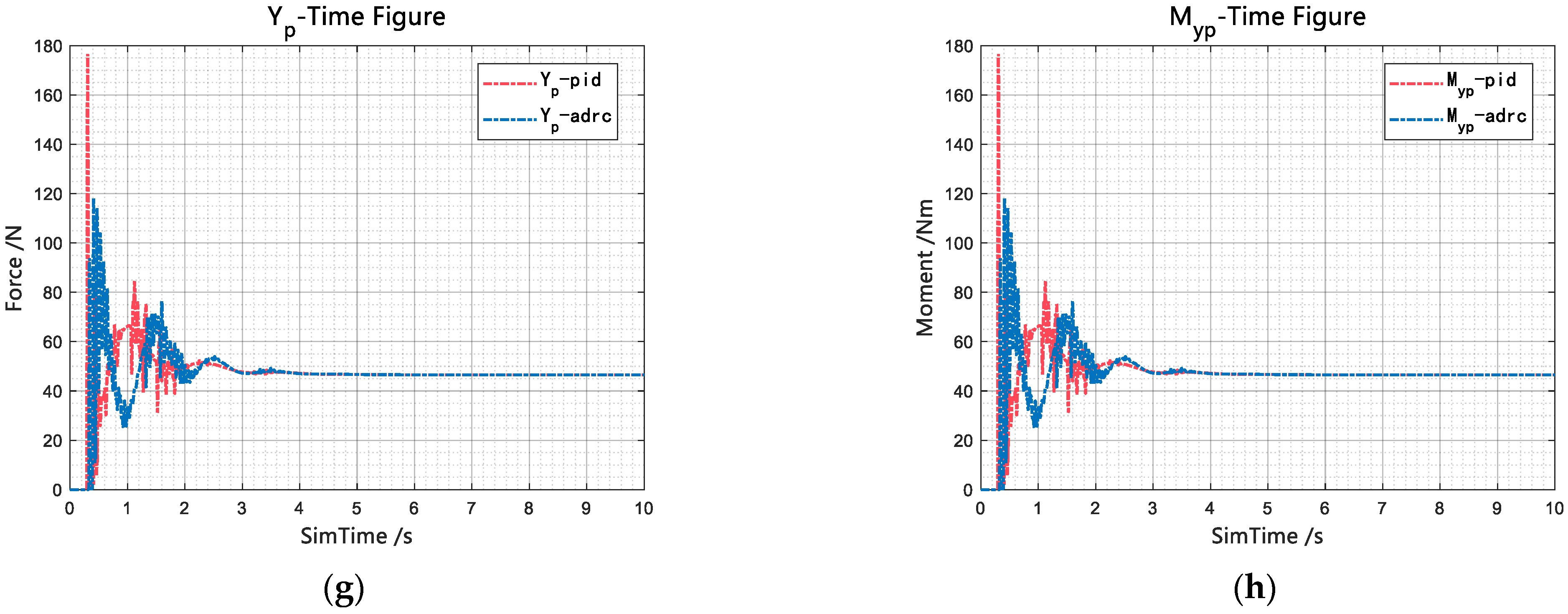
Figure 15, under the effective attitude angle regulation achieved by the inner-loop ADRC, the outer-loop error feedback controller achieves favorable control performance. Throughout the depth variation process, the depth command tracking differentiator, constrained by the selected fast factor, appropriately manages the transition process of the step inputs. This transition design is particularly essential for supercavitating vehicles characterized by pronounced dead zone nonlinearities. Significant fluctuations are observed in the hydrodynamic forces and moments, as shown in
Figure 15c,d. Nevertheless, the control system exhibits strong disturbance rejection capabilities because of the accurate disturbance estimation provided by the extended state observer combined with real-time disturbance compensation via the state error feedback control law. Consequently, smooth and stable depth tracking control is realized without noticeable overshoot.
5.6. Depth Control Without Cavity Length Regulation
In this subsection, the coupling effect of vehicle depth maneuvers on cavity evolution is neglected. The ventilation rate is fixed, and only depth control is applied. The simulation results are presented in.
As shown in
Figure 16, the cavity length decreases with decreasing depth. Around 1 s, the cavity length remains within the allowable range; however, by approximately 2.5 s, the cavity has contracted to nearly the length of the vehicle body. At this stage, the planing force calculation formula becomes completely invalid, and further vehicle dynamics computations are no longer meaningful.
These results clearly indicate that neglecting the influence of vehicle maneuvers on cavity evolution can lead to unrealistic predictions of vehicle dynamics. Therefore, it is necessary to incorporate a cavity length control loop to maintain the cavity within a reasonable range, thereby ensuring the fidelity and reliability of the vehicle dynamics model.
5.7. Depth Control of a Ventilated Supercavitating Vehicle
For comparative analysis, the parameters of the outer-loop depth controller were kept unchanged, while the inner-loop pitch angle control strategy was replaced with a classical PID controller, whose parameters are shown in Equation (60). This setup was used to compare the performance of the proposed cascaded ADRC scheme with that of the PID-based approach.
In the ventilation–cavity length control loop, the intelligent cavity length controller maintains the target cavity length by adjusting the ventilation rate according to the vehicle’s depth, velocity, and instantaneous cavity length. As shown in
Figure 17b, during the depth maneuver, the ventilation rate increases gradually with depth, with local fluctuations caused by the discrete switching between different ventilation levels. Once the depth stabilizes, the ventilation rate becomes constant. As depicted in
Figure 17a, under the ventilation control, the ventilated supercavity length remains stably regulated around the setpoint of 1.8 m throughout the maneuver, with a steady-state error of approximately 0.1 m. These results verify the high accuracy and robustness of the intelligent cavity length controller.
In the cavitator–motion control loop, the simulation results indicate that both PID-based and ADRC-based control strategies achieve satisfactory depth-tracking performance. However, when dealing with strong coupling effects and external disturbances, the ADRC-based control scheme exhibits superior dynamic characteristics. Compared with the PID controller, the ADRC reduces the peak glide force by approximately 30%, significantly enhancing the system’s stability and disturbance rejection capability.
Under the combined ADRC and reinforcement learning control framework, both cavity evolution and vehicle motion gradually stabilize during the depth-holding phase, with glide force oscillations effectively suppressed and a smooth transition achieved in depth control. As shown in
Figure 17c,d, the vehicle closely follows the depth command throughout the maneuver, demonstrating high tracking precision and favorable dynamic performance. The rise time and settling time are approximately 3 s and 5 s, respectively, with no overshoot observed. After stabilization, the vehicle maintains a depth of 5 m with a steady-state error of about 0.05 m. Owing to the efficient cavity length regulation and the active disturbance rejection capability of the ADRC, the cascaded control system effectively balances translational maneuvering and attitude stabilization, suppresses excessive glide forces, avoids instability induced by heterogeneous coupling channels, and achieves robust and smooth depth maneuver control.
6. Conclusions
This study investigated the depth-change maneuver control of ventilated supercavitating vehicles. Due to high travel speeds, non-stationary cavity evolution, and the nonlinear and coupled nature of the control channels, the control of supercavitating vehicles remains one of the most challenging problems in fluid mechanics and control theory. To address these challenges, an unsteady cavity evolution model was developed based on the principle of independent cross-sectional expansion and the strip theory, and coupled with a six-degree-of-freedom vehicle dynamics model to establish a heterogeneous coupled framework. Compared with simplified models, this framework provides a more comprehensive representation of the interactions between cavity dynamics and vehicle motion, as well as the coupling among different motion channels.
To mitigate instabilities observed in uncontrolled simulations—such as cavity collapse, planing force oscillations, and attitude divergence—a decoupled intelligent control framework was proposed. Within this framework, a Deep Q-Network (DQN) controller was employed to stabilize cavity length, while an Active Disturbance Rejection Controller (ADRC) was applied to pitch control to suppress planing force fluctuations and improve depth-tracking performance. The decoupled control strategy, with the DQN managing the cavity-length loop and the ADRC controlling the motion loop, reduces system complexity while enhancing robustness.
Simulation results demonstrate that the proposed approach effectively maintains the cavity length near the desired setpoint, suppresses planing force oscillations, and achieves precise and stable depth control during maneuvers. Comparative simulations with a classical PID controller show that, while both PID- and ADRC-based strategies achieve similar depth-tracking performance, the ADRC outperforms PID in handling coupling effects and external disturbances, reducing the peak planing force by approximately 30%, thereby significantly improving system stability and disturbance rejection. Under the combined DQN–ADRC control framework, cavity evolution and vehicle motion stabilize once the depth reaches the commanded value, achieving smooth and reliable depth control with a rise time of approximately 3 s, a settling time of 5 s, and a steady-state error of around 0.05 m. The main contributions of this study are as follows:
Heterogeneous Coupled Modeling: A six-degree-of-freedom heterogeneous coupled motion model for ventilated supercavitating vehicles was established, providing a more complete description of cavity–vehicle interactions and serving as a foundation for future maneuvering control studies.
Decoupled Control Design: A separated control strategy was proposed, in which a DQN controller manages the cavity-length loop and an ADRC controller governs the attitude loop, enhancing system robustness and control efficiency.
Intelligent Control Framework: A combined DQN-based cavity length control and ADRC-based depth control framework was developed and evaluated through simulations, demonstrating its effectiveness in maintaining cavity stability and achieving robust depth maneuver control.
In conclusion, this study holds significant scientific and engineering value in the modeling and control of ventilated supercavitating vehicles. It demonstrates both the novelty and practical potential of the proposed methodology while clearly identifying directions for future research.

