1. Introduction
Given that underwater vehicles are increasingly quieter, traditional acoustic detection methods have become inadequate, driving the need for non-acoustic detection technologies [
1]. Magnetic detection, which stands out as a promising alternative [
2], is a method to detect and identify underwater vehicles sailing in the presence of ocean waves by utilizing the generated magnetic fields [
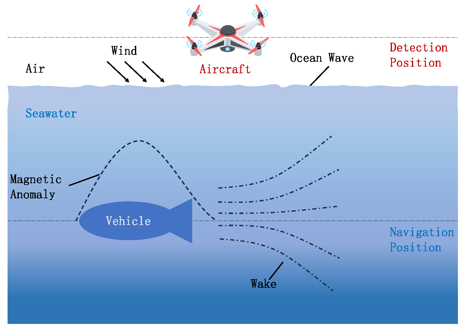
3]. As shown in
Figure 1, the magnetic fields measured by detectors can be primarily classified into three types based on their origin:
The magnetic anomaly field generated by the magnetization of a vehicle’s ferromagnetic hull due to the geomagnetic field [
4];
The wake magnetic field generated by the vehicle’s motion disturbing the seawater flow and cutting through the geomagnetic field [
5];
The ocean wave magnetic field generated by the interaction of wind-driven surface waves with the geomagnetic field [
6]. This kind of field is generally considered noise.
Figure 1.
Schematic diagram of mechanism of magnetic anomaly generation.
Figure 1.
Schematic diagram of mechanism of magnetic anomaly generation.
A magnetic anomaly field, present when the vehicle is both stationary and moving, is a static field that quickly diminishes with distance despite its large magnitude. In contrast, a wake magnetic field, generated only during motion, persists for longer and over a larger domain [
7].
Magnetic Anomaly Detection (MAD) is widely used to identify disturbances in the geomagnetic field generated by ferromagnetic underwater vehicles [
8], and is based on mathematical models categorized as mathematical theory and magnetic body methods [
9]. Among the former, the Finite Element Method (FEM) calculates magnetic fields by assessing the scalar magnetic potential in finite domains, and tools such as SIMULIA Opera [
10], ANSYS Maxwell [
11], and COMSOL Multiphysics [
12] are widely used for modeling magnetic characteristics. In magnetic body methods, a hybrid model combining a rotating ellipsoid for the hull’s magnetic signature [
13] and a dipole array for the internal machinery enables efficient magnetic anomaly assessment [
14]. Researchers have focused on the magnetic anomaly fields of stationary objects such as cables [
15], pipelines [
16], and sunken ships [
17]. Under real-world conditions, vehicles usually move along certain courses at various depths [
18], which directly leads to variations in the detection distance between vehicle and aircraft [
19]; while this can be effectively modeled [
20], the influence of a vehicle’s speed on the spatial and temporal signatures of its magnetic field remains under-studied.
Underwater vehicles in seawater generate significant hydrodynamic wakes, including Kelvin [
21], vortex [
22], and internal wave wakes [
23]. Kelvin wakes are the most significant, as they are surface waves [
24], and their magnetic field can be modeled based on the wake wave height [
25], and its spatial distribution is influenced by factors such as the vehicle’s length [
26], speed, and depth [
27]. However, there is a gap in research regarding how changes in a vehicle’s course affect the wake magnetic field, and the relevant temporal dynamics are not well understood. Additionally, the impact of navigational changes and conductivity on the wake magnetic field model has not been studied, nor has there been a combined study of the overall magnetic field resulting from the superposition of the magnetic anomaly and the wake magnetic fields.
In the context of underwater vehicle detection, it is crucial to consider the various sources of magnetic noise that can affect vehicle detectability, such as platform noise (up to 10 nT) [
28], magnetic sensor noise (about 0.00087 nT) [
29], and environmental noise (0.025–1 nT) [
30]. Among these, environmental noise, especially ocean wave noise, is of particular interest in this study.
Figure 1 indicates that ocean wave motion above the sea surface generates a magnetic field by interacting with the geomagnetic field. According to surface wave theory, the induced ocean wave magnetic field is correlated with wave height and length, as described by the Weaver model [
31]. Research on the variation in the induced magnetic field of multi-frequency ocean waves in finite-depth water [
32], has shown that variations in seawater electrical conductivity can impact the magnetic fields generated by different wave types [
33]. However, previous studies have primarily focused on deriving the expression of the induced magnetic field in the air layer, without investigating the effects of other factors, such as changes in wind speed and direction. Moreover, there is a lack of research on the temporal characteristics of ocean wave magnetic fields and the impact of ocean waves on a vehicle’s magnetic field.
In summary, prior research has largely focused on separately analyzing the magnetic anomaly and wake magnetic fields of underwater vehicles, and the ocean wave magnetic field. Since magnetic sensors detect the composite magnetic field resulting from both the underwater vehicle and the environment, studying the spatiotemporal characteristics of these three fields together is crucial. This study aims to combine the modeling of these magnetic fields to clarify the spatiotemporal characteristics and attenuation patterns of the composite field, and analyze how it is affected by vehicle motion and marine environmental parameters.
The remainder of this paper is organized as follows: In
Section 2, we cover the basic theories of the magnetic fields generated by underwater vehicles and ocean waves. In
Section 3, we present simulations of magnetic fields in various scenarios, and in
Section 4, we discuss their results. In
Section 5, we present the conclusions of this study.
2. Basic Theory of Magnetic Fields of Underwater Vehicles
The magnetic fields generated by a vehicle and the ocean wave magnetic field are analyzed using the International Geomagnetic Reference Field (IGRF) model to describe the background geomagnetic field, and data from the World Ocean Atlas (WOA) to characterize the electrical conductivity of seawater. These varying magnetic fields are then combined to obtain a composite magnetic field.
2.1. Basic Model of the Geomagnetic Field
Considering the close relationship of the geomagnetic field, the vehicle-generated magnetic field, and the ocean wave magnetic field, it is essential to uniformly set the relevant parameters of the geomagnetic field. Within the computational domain, this field can be considered uniform, with constant magnitude and direction. To represent this, we adopted the latest IGRF-14 model [
34]. As shown in
Figure 2, the positive
x-axis points to the geographic north, the positive
y-axis points to the geographic west, and the positive
z-axis is perpendicular to the
-plane upwards.
The projection of the geomagnetic induction intensity (
) on the
-plane is
, and the angle between them is the magnetic inclination,
, which is positive downward. The angle between
and the northward direction is the magnetic declination,
, which is positive eastward. The geomagnetic induction intensity is expressed as
where
represents the geomagnetic induction intensity;
,
, and
represent unit vectors along the
x-,
y-, and
z-axes, respectively.
The values of the geomagnetic field vector intensity along the
x-,
y-, and
z-axes of the coordinate system are denoted by
,
, and
:
where
represents the geomagnetic field intensity, with
, where
is the permeability of free space, approximately
H/m.
2.2. Mechanism of Magnetic Field Generation for Underwater Vehicles
The magnetic fields linked to the underwater vehicle itself are primarily of two types: the magnetic anomaly field due to ferromagnetic material and the wake magnetic field resulting from the vehicle’s motion. Although these fields originate from distinct processes, they both intricately influence underwater vehicle detection, so it is necessary to understand their basic principles.
2.2.1. Magnetic Anomaly Field of a Ferromagnetic Underwater Vehicle
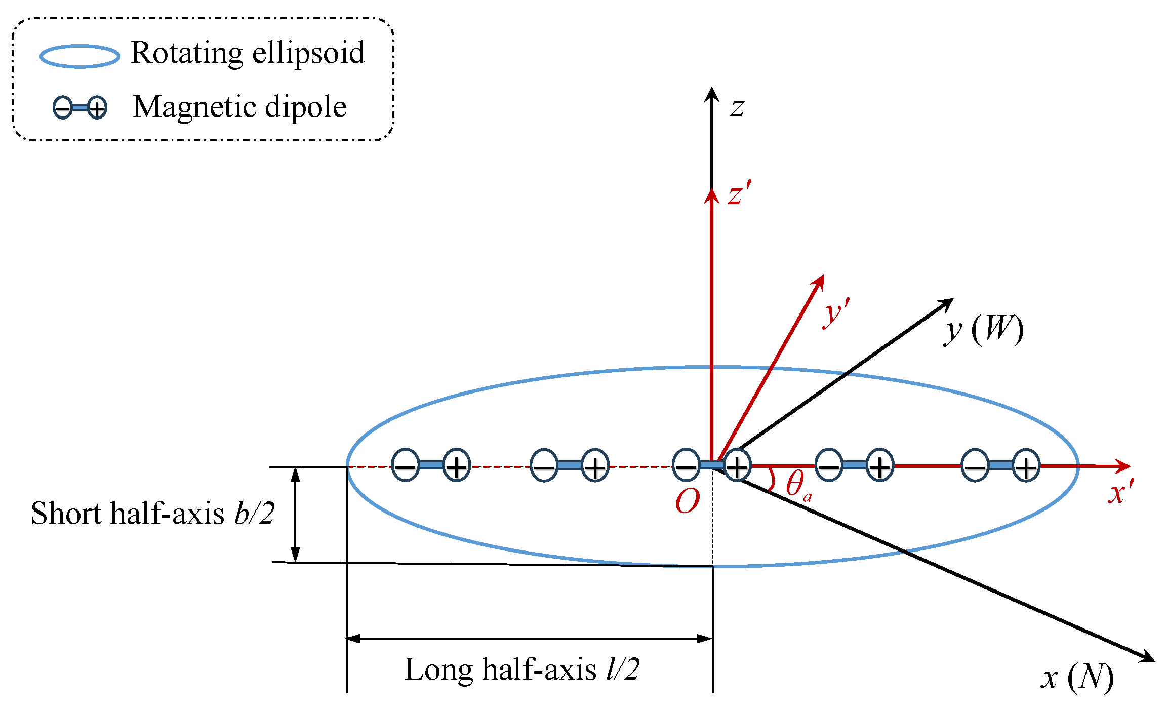
Magnetic anomalies are closely related to the inherent properties of ferromagnetic materials. The basic model for their calculation primarily consists of a combination of the FEM and magnetic body simulation. Here, the hybrid model is chosen for its accurate simulation of both the ferromagnetic shell and internal equipment’s magnetic field, offering higher calculation accuracy and efficiency. The vehicle’s hull is simplified as a rotating ellipsoidal model, where the ellipsoid’s major axis corresponds to the length (
l) of the underwater vehicle and the minor axis to its breadth (
b). The magnetic dipoles are evenly distributed along the central axis of the ellipsoid, as shown in
Figure 3. We take the center of the dipole model as the coordinate origin, the sea level as the
-plane, and the direction perpendicular to the sea plane and upward as the
z-axis, establishing a right-handed rectangular coordinate system. The geomagnetic field value in the geographic coordinate system is converted to the vehicle coordinate system; the course of the vehicle is
, and the westward declination is positive.
The transformation relationship between the vehicle coordinate system and the geographic coordinate system for the vehicle magnetic field is obtained as
where the subscripts
,
, and
represent the vehicle coordinate system, while
x,
y, and
z represent the geographic coordinate system.
Firstly, the radiated magnetic field of the electromechanical equipment inside the underwater vehicle is obtained based on the magnetic dipole array model. According to the magnetization law of an ellipsoid model in an external field, the three components of the vehicle’s magnetic moment have a functional relationship with the three components of the geomagnetic field, which can be expressed with specific formulas:
where
,
, and
are the magnetic moments of the magnetic dipole along the
x-,
y-, and
z-axes, respectively;
L and
S are the demagnetization factors in the long- and short-axis directions of the vehicle, respectively. The empirical formulas for the demagnetization factors of ellipsoidal ferromagnet are as follows [
35]:
where
is the ratio of the long and short semi-axes of the ellipsoid model and
.
The magnetic anomaly vector fields (
,
, and
) of the magnetic dipole array at detection point
P are expressed as [
36]
where
N is the total number of magnetic dipoles. The coefficients of the coefficient matrix are as follows [
37]:
where
is the distance from the
detection point (
) to the
dipole (
). The
x-coordinate of the magnetic dipole is
, and the dipole spacing is
. The relationship between the total magnetic anomaly field (
) and the vector fields is
Therefore, the intensity of the magnetic anomaly field can be obtained, and the magnetic anomaly induction intensity can be derived as
Then, the rotating ellipsoid model is established to simulate the hull of the vehicle, and the FEM is employed to solve for its radiated magnetic field. We solve for the magnetic anomaly field of an ellipsoid by choosing the Steady method, according to Gauss’s magnetic law:
where
represents the ellipsoid’s magnetic anomaly field intensity, given by
where
represents the reference magnetic potential. We substitute Equation (
11) into Equation (
10) to obtain the differential equation
The insulating boundary condition of the geomagnetic field at the external boundary of the computational domain is set as follows:
where
is the boundary normal vector of the ellipsoid’s outer surface. Equation (
13) can be further simplified to
Therefore, the magnetic anomaly field intensity can be determined, and the magnetic anomaly induction intensity of an ellipsoid can be derived as
where
is the relative magnetic permeability of the hull material and
.
Finally, the total magnetic anomaly induction intensity of the equivalent hybrid model can be obtained through superimposition:
The basic parameters of a specific underwater vehicle at a given location can be identified, and this information enables the quantitative calculation of the magnetic anomaly intensity induced by the hybrid model by using Equation (
16).
2.2.2. Wake Magnetic Field of an Underwater Vehicle in Motion
When an underwater vehicle travels at a constant speed along a path aligned with the positive
x-axis in seawater, it generates free surface waves. These waves include both diffusion and transverse waves, creating a Kelvin wake as depicted in
Figure 4. The most significant surface fluctuations occur within a range of 16° to 19.5° (half divergence angle) on either side of the vehicle’s trajectory, forming a V-shaped pattern overall [
38].
Using the above-mentioned rotating ellipsoid model to describe underwater vehicles, the free-wake spectrum function can be expressed as follows [
39]:
where
is the vehicle’s volume, with
;
is the wake’s wavenumber, with
;
is the vehicle’s speed;
g is the gravitational acceleration, approximately 9.81 m/s
2; and
is the wake’s propagation direction, which varies within
on both sides of the symmetry axis, which is indicated by the red dashed line in
Figure 4.
Assuming that seawater is an incompressible fluid with constant volume, it meets the continuity equation
. The wake velocity field can be expressed as [
39]
where
t is time and
is the wake’s angular frequency, with
. The vector
is given by
where
is the detection height of the aircraft and
is the diving depth of the vehicle.
According to Faraday’s law of electromagnetic induction, as the wake velocity vector (
) crosses the geomagnetic field vector (
), the electric field (
) is induced perpendicularly to both, which in turn generates current density. Therefore, the relationship between the wake magnetic field (
) and the velocity field (
) satisfies the following Maxwell equations:
where
and
are the electrical conductivity and dielectric constant of the medium, respectively; and the subscripts
correspond to the air and seawater domains, respectively.
In this study, WOA23 temperature and salinity data from the WOA [
40] are used for the precise calculation of seawater electrical conductivity, which is given by
where
S is the salinity;
T is the temperature;
P is the seawater pressure, which is dependent on sea depth;
R is the conductivity ratio;
is the standard seawater electrical conductivity, with a value of 4.2914 S/m;
and
are temperature and pressure correction factors, respectively.
Assuming that the influence of the seabed is disregarded and considering that the wave height of free surface waves in seawater is much smaller than their length, the free surface is approximated to a plane
based on the following identical equation [
41]:
We take the curl on both sides of the first expression in Equation (
20), substitute the third expression, and simplify Equation (
22) to obtain the following differential equation:
Equation (
23) represents a linear expression. In our research study, we only need to consider a single harmonic component by accounting for the angular frequency (
). The wake magnetic field intensity generated by an underwater vehicle which satisfies the above differential equation can be expressed as [
41]
where the vector
is given by
where
and
are the wake’s amplitude and phase vectors, respectively. These are given by
respectively, where
and
are the propagation parameters of the vehicle wake in the medium, with
and
.
Substituting Equations (
26) and (
27) into Equation (
25) gives
; then,
can be obtained from Equation (
24). Therefore, the wake magnetic field can be obtained, and the wake magnetic induction intensity can be derived as
2.3. Mechanism of Magnetic Field Generation for Ocean Waves
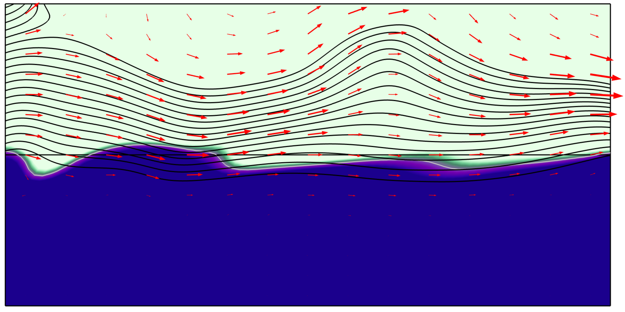
Waves are relatively common movements of seawater caused by wind, and they usually occur on the sea surface, as shown in
Figure 5. The red arrows show the wind direction, with the arrow length indicating the speed of the wind field. Moreover, the direction of the black streamline fluctuations indicates the direction of ocean wave undulations, where denser streamlines indicate higher velocity. The blue coloration in
Figure 5 represents the volume fraction of seawater: lighter shades denote areas with a lower volume fraction of seawater, while darker shades indicate regions with a higher volume fraction.
The wave spectrum is a Fourier transform that describes the correlation function of sea surface undulations, and represents the frequency distribution of wave energy relative to its constituent waves [
42]. Since the Joint North Sea Wave Project (JONSWAP) spectrum is regarded as the international standard wave spectrum, the wave spectrum in this study (
) is represented by the JONSWAP spectrum [
43] and the direction spectrum proposed by Cote [
44]:
where
is the wind direction angle between the wind’s propagation direction and the
x-axis;
is the wave’s propagation direction, ranging within
on both sides of
. The parameters
A and
F in the Cote direction spectrum are given by
and the parameters
K and
J in the JONSWAP spectrum are given by
where
is the ocean wave angular frequency, which satisfies the dispersion relationship
;
is the ocean wavenumber;
is the wind angular frequency, with
; and
is the wind speed 19.5 m above sea level.
Recent studies have shown that wave dynamics such as tidal effects and Large-Scale Coherent Structures can influence the movement of targets in the ocean to a certain extent, specifically influencing formation and propagation, especially in long-period waves [
45]. To facilitate the subsequent linear superposition of various magnetic fields and efficiently investigate the impact of individual parameters on the resulting composite magnetic field, this study employs a simplified mathematical model of ocean waves to derive solutions. Ocean waves can be described as the linear superposition of
sine waves, and their velocity field can be expressed as [
46]
where
M is the number of both frequency and propagation;
is the initial phase, which is randomly distributed within
; and the vector
is given by
where
is the amplitude and
.
Similar to that of wakes, the magnetic field of ocean waves is also induced by the latter’s velocity field driven by the wind. By replacing the subscript
w with
m and the integration operation with the summation operation in Equations (
20) and (
23), we express the ocean waves’ magnetic field as [
46]
where the vector
is given by
where
and
are the ocean waves’ amplitude and phase vectors. These are given by
respectively, where
and
are the propagation parameters of ocean waves in the medium, with
and
.
Substituting Equations (
38) and (
39) into Equation (
37) gives
; then,
can be obtained from Equation (
36). Therefore, the ocean wave magnetic field can be obtained, and the ocean wave magnetic induction intensity can be derived as
By comparing the derivation processes of the expressions of vehicle wake and ocean wave magnetic fields in this study, it is found that they present great similarity, and the structure of the obtained coefficient expressions is the same. Because vehicle wake and ocean waves are both long gravity waves that occur on the sea surface, their similar kinematic behavior leads to analogous mathematical formulations and functional structures in their simulation theories. Additionally, the models assume a consistent geomagnetic field, which results in similar expressions for the magnetic fields generated by the motion of seawater.
2.4. Composite Magnetic Field Solution Method for Navigation Vehicles in the Presence of Ocean Waves
To obtain the composite magnetic induction intensity, we apply the principle of linear superposition, which is valid under the assumptions of the linearity and additivity of the individual magnetic fields. The magnetic anomaly induction intensity (
), wake magnetic induction intensity (
) and ocean wave magnetic induction intensity (
) are superimposed to obtain the composite magnetic induction intensity (
) as
which simplifies the analysis by considering each component separately before integrating it with the others to form a comprehensive view of the composite magnetic field.
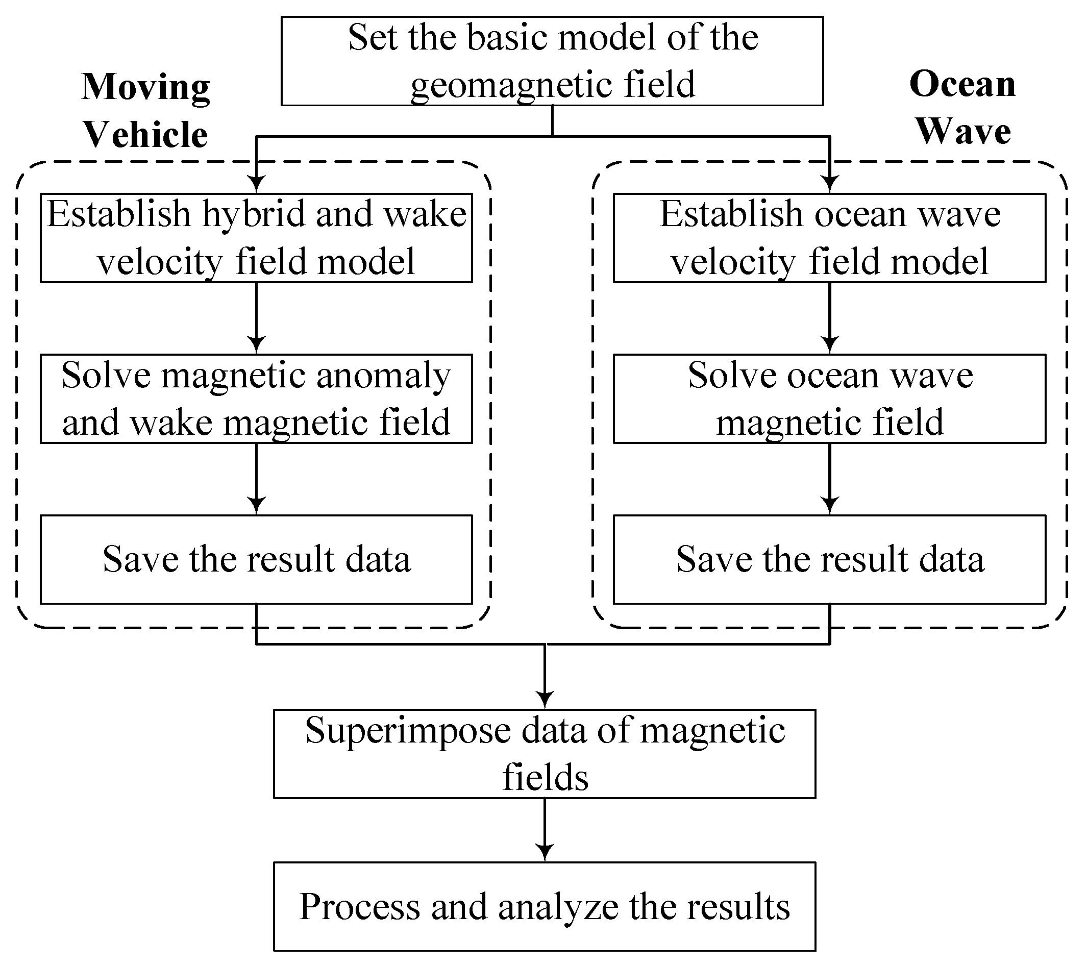
The solution process for the composite magnetic field is illustrated in
Figure 6. By integrating these magnetic fields, a more comprehensive analysis of the detected magnetic field can be conducted. The composite magnetic field includes the magnetic anomaly and wake magnetic fields generated by the underwater vehicle, which are the signals of interest, and the magnetic field generated by ocean waves, which acts as noise in this context.
Under the quasi-static limit, the changes in the magnetic field are slow compared with the vehicle’s motion and the wave dynamics. This enables us to treat the magnetic field as essentially static over the short timescale of these dynamic processes, simplifying analyses and calculations. This approximation is valid when
where
is the timescale of the changes in the magnetic field and
is the timescale of the dynamic processes.
In our scenario, adjustments to the magnetic field happen over a period of minutes, whereas changes in the vehicle’s speed and the dynamics of the waves occur within seconds. Consequently, the magnetic field can be approximated as quasi-static, meaning that it changes slowly enough relative to the fast dynamics of vehicle motion and wave interactions, which validates the use of this approximation in our analysis.
3. Simulation Results of Underwater Vehicle’s Magnetic Fields
The simulations presented in the following provide a detailed examination of an underwater vehicle’s magnetic field characteristics under multiple conditions. We first address the complexities involved in modeling and analyzing the magnetic fields generated by underwater vehicles, laying the foundation for the subsequent discussion on the magnetic fields of a vehicle below a calm sea surface and the composite magnetic field of a vehicle in the presence of ocean waves.
3.1. Problem Description
According to the IGRF-14 model, we set the observation position as the sea area at 16°15′50′′ N and 109°40′12′′ E, and calculate the geomagnetic induction intensity, the magnetic inclination and declination angles, as shown in
Table 1. The geomagnetic induction intensity is primarily directed along the
x-axis, with the
z-axis component being the next-most significant and the
y-axis component being the smallest.
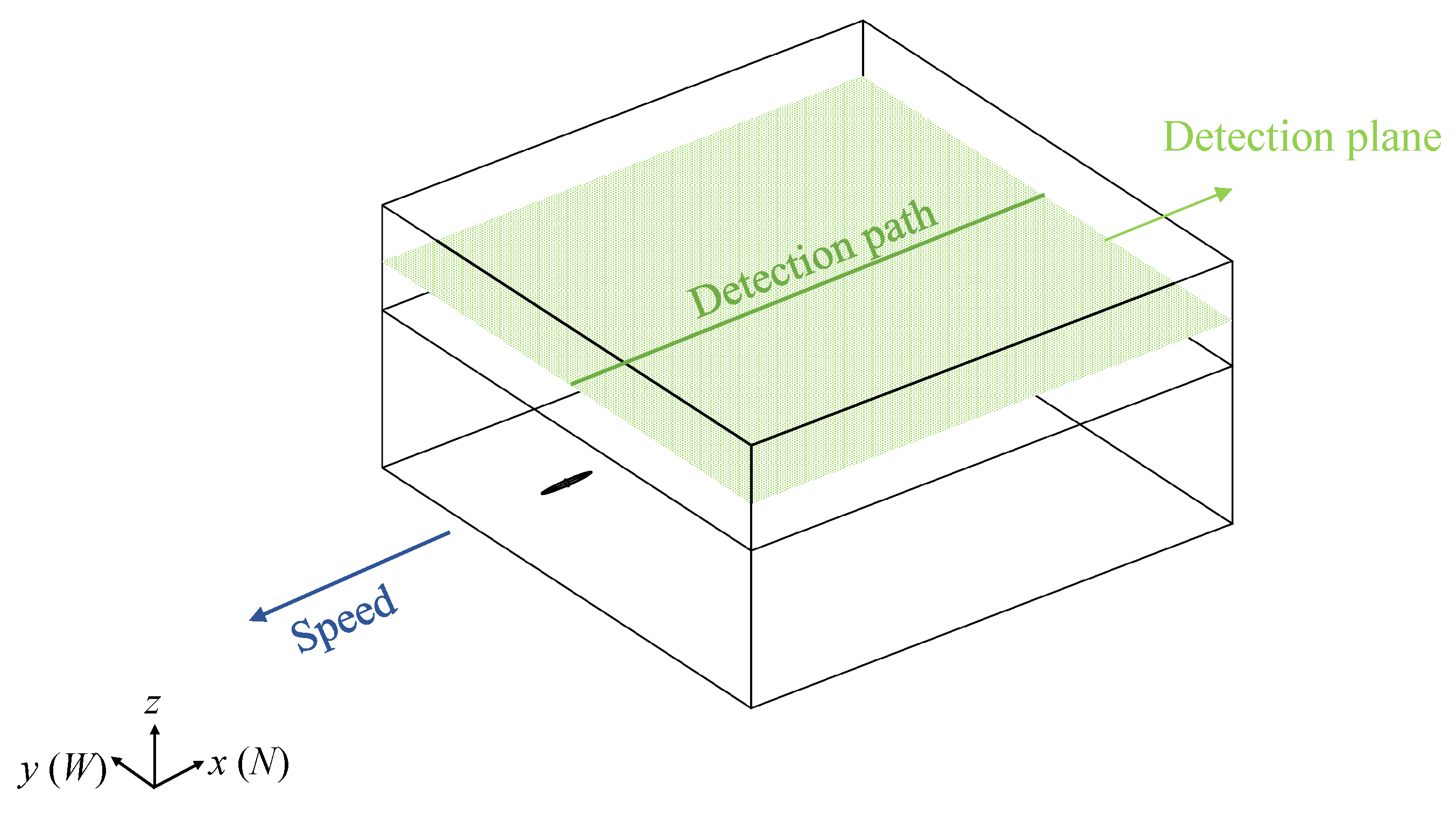
Figure 7 shows the relative positional relationship between the aircraft detection points and the moving underwater vehicle, where the blue ellipse represents the starting position of the vehicle; the diving depth is set to 80 m, and the vehicle moves at a constant speed along the
route in the negative
x-axis direction. The red circle represents the detection point of the aircraft, which is located at point
P, and the detection height is set to 50 m.
Detection distance
represents the Closest-Path Approach (CPA) length between the detection point and the moving vehicle [
47] and can be expressed as
where
is the vertical distance between the moving vehicle and the sea level,
is the vertical distance between the detection point and the sea level, and
is the horizontal distance between the point and the vehicle. The time duration (
t) is
The entire computational domain is divided into seawater (
) and air (
). The electrical conductivity of seawater is taken at a depth of 10 m, calculated to be 5.07 S/m (refer to Equation (
21)), and the relative permittivity of seawater is set to 80. The joint model of the underwater vehicle and the computing domain is shown in
Figure 8. The vehicle is located inside the sea area, the detection plane is within the air domain and parallel to the sea level, and the detection path is a straight line along the
x-axis (
).
The computational domain’s outer boundary is set far from the vehicle to ensure that the boundary conditions have no effect on the simulation results. It extends over ten times the maximum wavelength in all directions from the vehicle. We apply boundary conditions to simulate the air–seawater environment by using a 2D projection of the 3D domain equation for the vehicle’s hull, which includes the hull’s thickness and permeability. This method effectively models highly permeable thin sheets and aligns the boundary conditions with the background magnetic field.
The main parameters of the simulation model are shown in
Table 2. To enhance stability, the aspect ratio of the vehicle is set to 8.8. The hull of the underwater vehicle is made of high-strength steel that can withstand extremely-high water pressure [
48]. After demagnetization, the relative magnetic permeability of the hull usually drops significantly, ranging from 100 to 300 [
49]. Finally, the vehicle model is divided with the custom meshing method, yielding 179,026 boundary elements and 2174 edge elements.
A mesh convergence study was conducted to validate the independence of our results from the mesh size and boundary conditions. It involved refining the mesh incrementally and monitoring the change in the magnetic field intensity at key points within the domain; the mesh was considered converged when the relative change in magnetic field intensity fell below 1% between successive refinements. The convergence graph in
Figure 9 illustrates the mesh refinement and the corresponding changes in magnetic field intensity, showing that the error gradually decreases with the increase in the number of iterations and eventually stabilizes or reaches the preset convergence standard. This indicates that the calculation process is convergent and that the result is relatively accurate.
3.2. Different Magnetic Fields of a Vehicle Under a Calm Sea Surface
In this section, we present the analysis of the vehicle’s magnetic fields under calm sea conditions, starting with the scenario where there are no ocean waves. When stationary, the vehicle induces only a magnetic anomaly field, while when motion, it induces both a magnetic anomaly field and a wake magnetic field, which form the total vehicle magnetic field.
3.2.1. Magnetic Field Distribution of Vehicle at Starting Position
Initially, we examine the scenario of the vehicle’s starting position at a depth of 80 m, denoted by point
Q in
Figure 7. When stationary along the negative
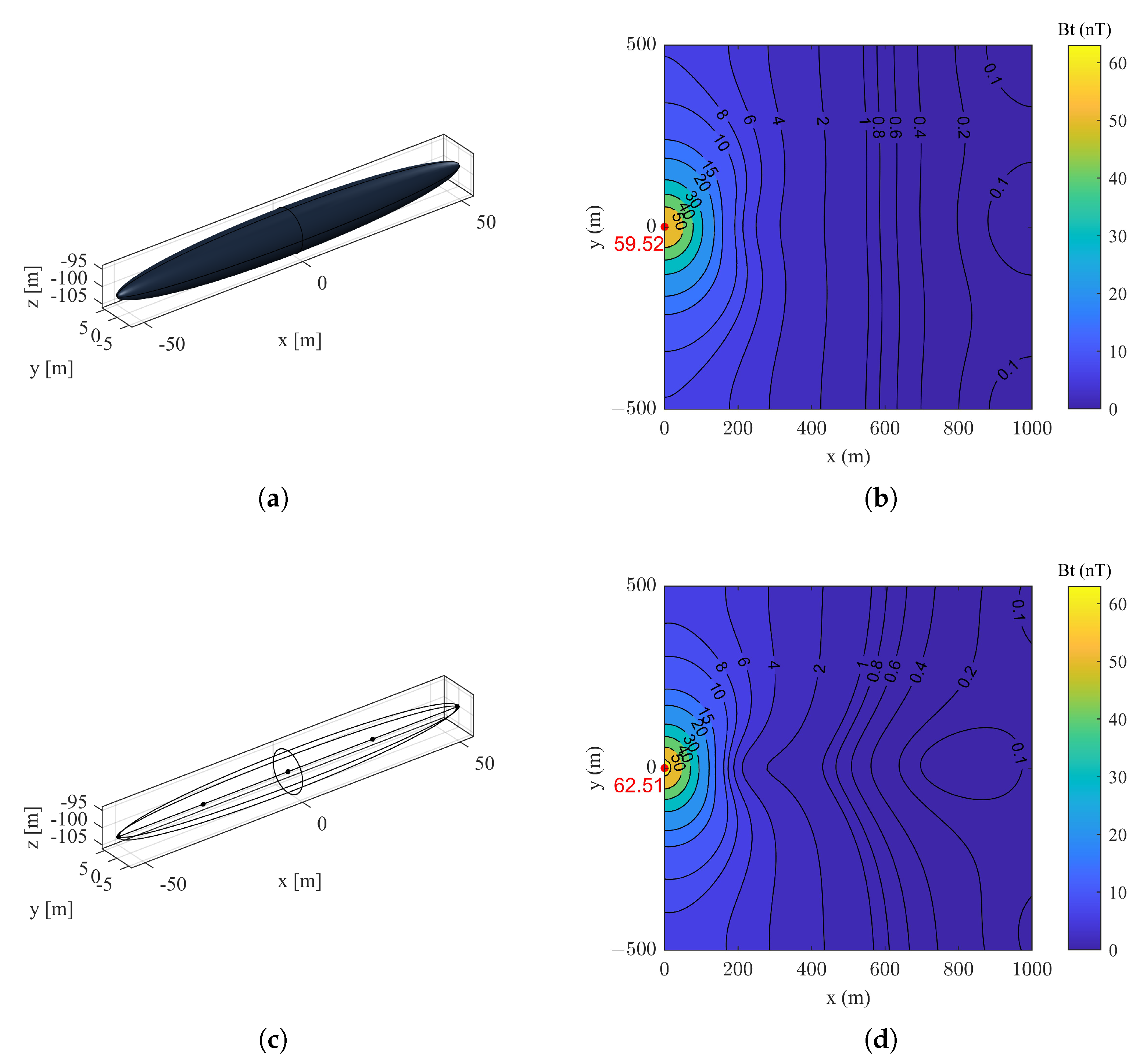
x-axis, the underwater vehicle generates only a magnetic anomaly field. The magnetic anomaly fields obtained on the detection plane by using the rotating ellipsoid model and the hybrid model are shown in
Figure 10. Specifically,
Figure 10b shows that the magnetic anomaly distribution of the ellipsoid model is concentrated, with a peak magnetic induction intensity of approximately 59.52 nT. In contrast, the hybrid model in
Figure 10d, which combines an ellipsoid model and an array of five magnetic dipoles, generates a stronger magnetic anomaly field, with a peak magnetic induction intensity of approximately 62.51 nT. It can be clearly seen that the contour pattern of the hybrid model is more elongated, reflecting the influence of the magnetic dipole array source in the hybrid model.
When the underwater vehicle maintains starting position depth
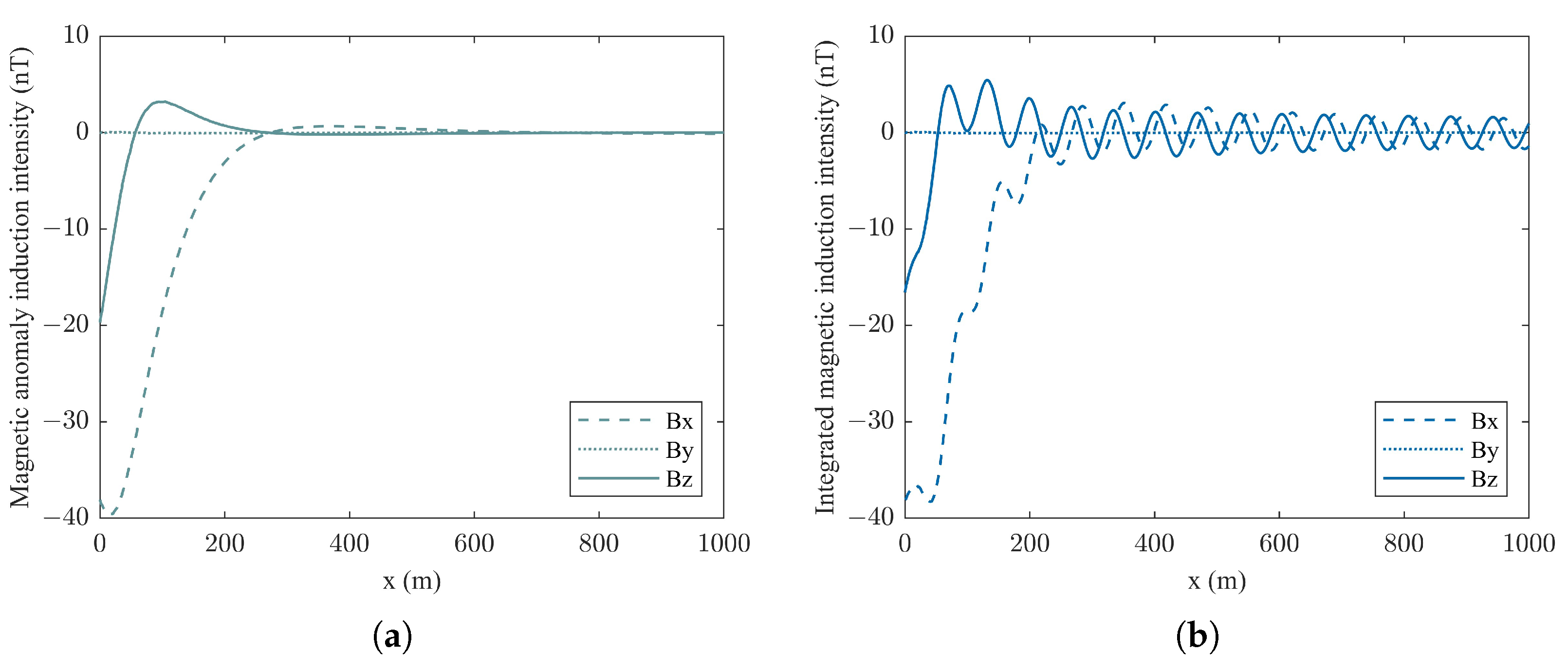
Q and sails at a speed of 20 kn, it induces an integrated magnetic field along the detection path shown in
Figure 11, which includes both a magnetic anomaly field and a wake magnetic field.
Figure 11a displays the magnetic anomaly vector fields, where the
x-,
y-, and
z-components periodically vary along the
x-axis. Moreover,
Figure 11b displays the integrated magnetic field, which decays more slowly, extending the detection range and improving underwater vehicle tracking. The standard deviation analysis indicates that the
x- and
z-components of the magnetic fields exhibit significant differences, with standard deviations of 1.6155 nT and 1.6284 nT, respectively. In contrast, the
y-component shows negligible standard deviation, 0.0013 nT, implying minimal influence on the overall magnetic field distribution along the detection path.
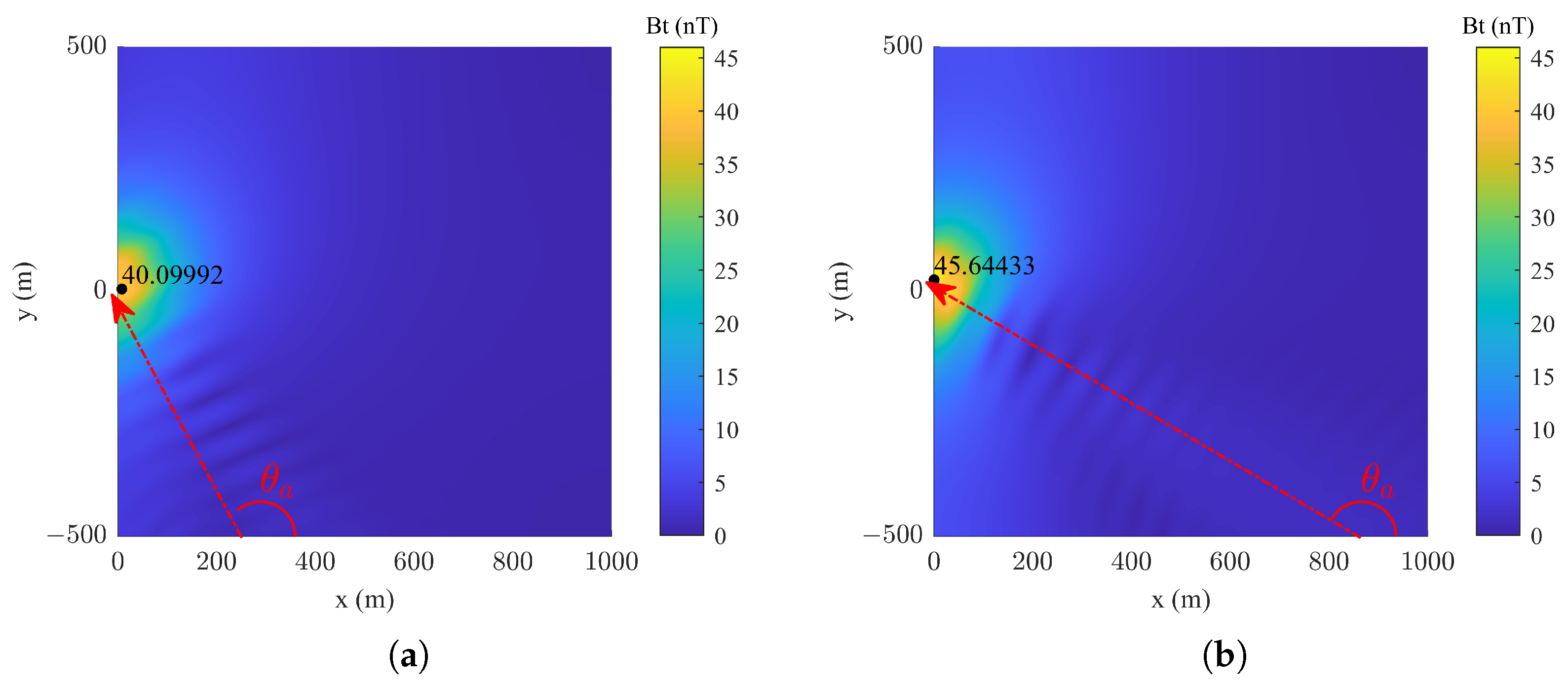
Since the wake magnetic field is superimposed on the magnetic anomaly field during the vehicle’s movement, the influence of different course angles on the detection plane at the initial moment on the integrated magnetic field is investigated, as shown in
Figure 12. As the vehicle’s course changes, so does the integrated magnetic field’s pattern and intensity, showing that the direction greatly influences the detected magnetic signature. The wake magnetic field overlays the magnetic anomaly field, spreads, and changes in intensity with different courses, suggesting that the course affects magnetic detection. Importantly, the wake magnetic field distribution is symmetric with respect to the vehicle’s course.
3.2.2. Variation in Magnetic Field of Vehicle in Motion
If we suppose that the vehicle is moving at a constant speed in a straight line from point
, it can be inferred from Equation (
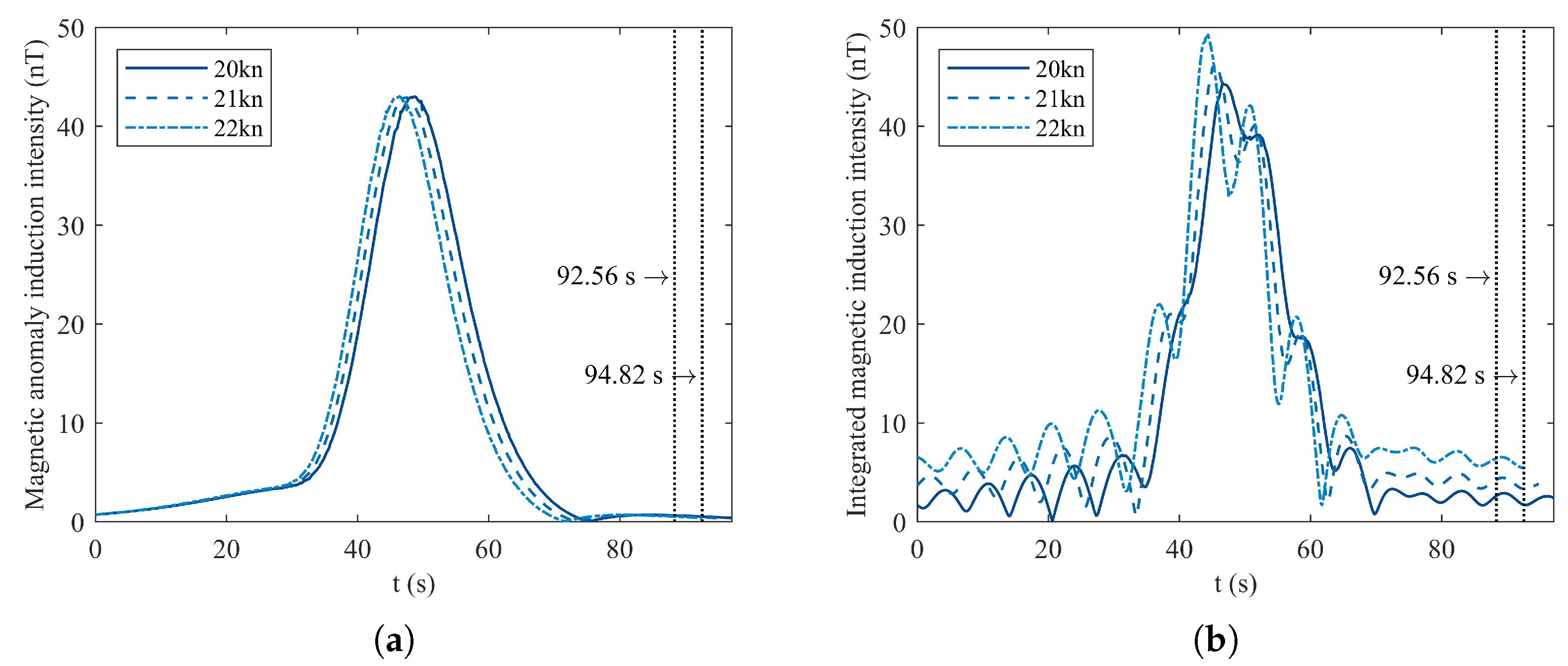
17) that, in theory, its speed influences the wake magnetic spectrum, thereby affecting the wake magnetic field. The simulation results of the temporal characteristics of the magnetic anomaly field and the vehicle’s integrated magnetic field at different speeds at detection point
are illustrated in
Figure 13. The magnetic anomaly field intensity remains consistent over time regardless of the vehicle’s speed, confirming that speed does not influence intensity. On the other hand, the vehicle’s integrated magnetic field, which includes both the magnetic anomaly field and the wake magnetic field, exhibits a distinct difference in peak intensity and duration at the two speed values. A higher speed results in higher peak intensity but shorter duration, indicating that while speed does not affect the magnetic anomaly field, it significantly impacts the wake magnetic field characteristics.
When the vehicle moves to midpoint
(refer to
Figure 7), it is positioned directly below detection point
P; thus, the magnetic induction intensity is at its peak at approximately 48 s, as shown in
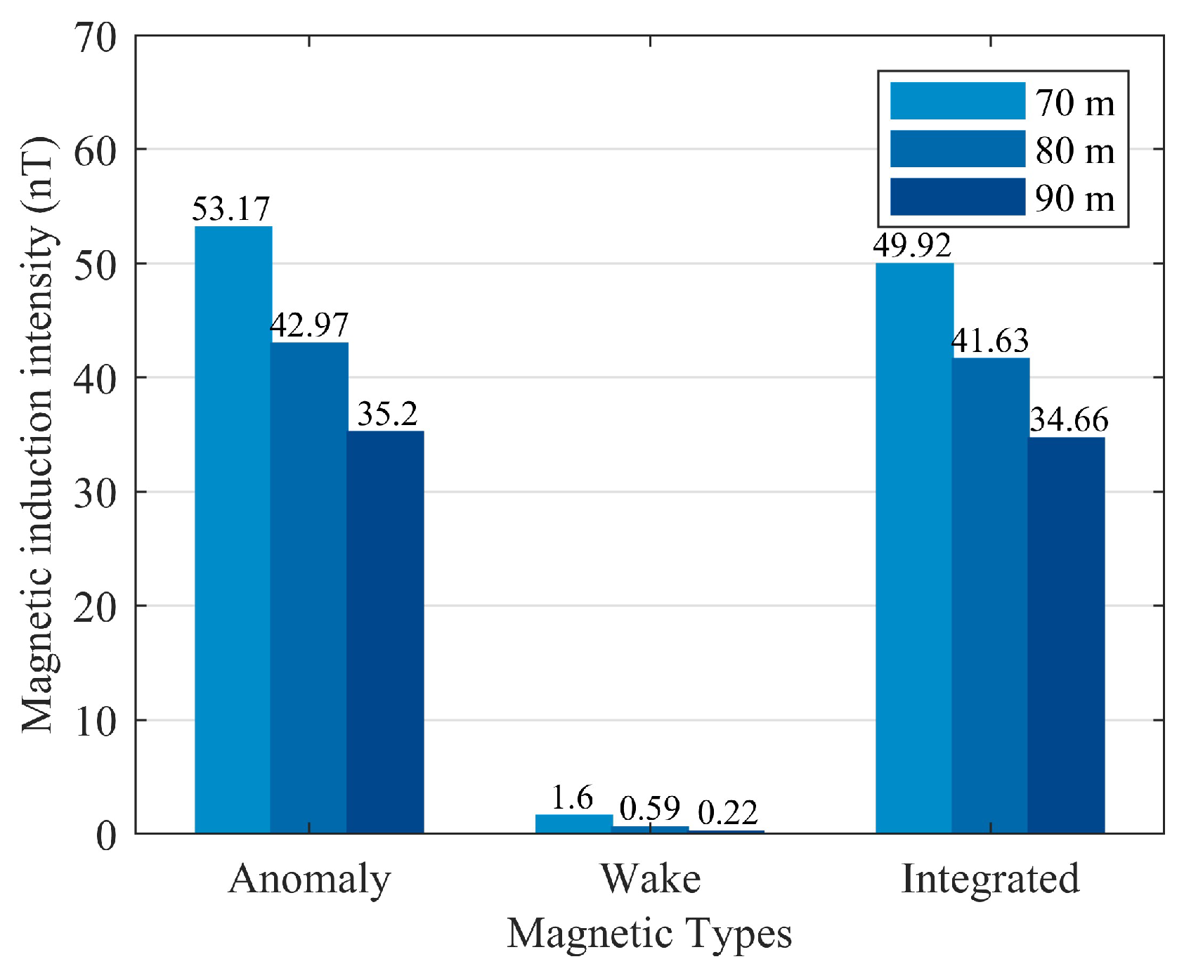
Figure 13. The influence of the diving depth on the vehicle’s magnetic fields at detection point
P is shown in
Figure 14. The intensity of the magnetic fields decreases with depth, indicating that a greater depth results in weaker magnetic anomaly fields. Among the considered fields, the wake magnetic field is the smallest, but the attenuation rate is the fastest, indicating that the wake magnetic field is more affected by depth changes.
3.3. Composite Magnetic Field of a Constantly Moving Vehicle in the Presence of Ocean Waves
The parameters of ocean waves and seawater electrical conductivity mainly affect the wake magnetic field and have no significant impact on the magnetic anomaly field. Therefore, in this section, we study the influence of ocean waves on the wake magnetic field under the assumption that the vehicle is moving at a constant speed in a straight line along the x-axis.
3.3.1. Influence of Wind Speed and Direction Changes Under Different Sea States
Sea state codes are categorized based on wind speed and wave height [
50], which are closely related to the Beaufort scale. The latter, ranging from Levels 0 to 12, provides a standardized method to gauge wind force based on its visible effects on the sea’s surface [
51]; when the sea state reaches Code 8 or above, the wind force is already above Level 10 on the Beaufort scale, and ocean navigation is quite dangerous. In this study, we only consider wind speed and wave height values for sea states up to Code 7, as shown in
Table 3.
We selected the maximum wind speeds for sea states corresponding to Codes 1 and 7 and compared the distributions of the wave magnetic field on the detection plane, as shown in
Figure 15. An increase in wind speed from 3 kn to 47 kn leads to a noticeable enhancement in the wave magnetic induction intensity. The distribution pattern also shifts from being more localized and less intense to being more widespread and intense, highlighting the significant impact of wind speed on the magnetic field generated by ocean waves.
According to
Table 3, white waves appear when the sea state reaches Code 4 and wave height exceeds 1 m. To ensure the vehicle’s stability and buoyancy, the simulation was conducted under sea state Code 3 (Beaufort Level 3) with a wind speed of 10 kn and a direction of 0°.
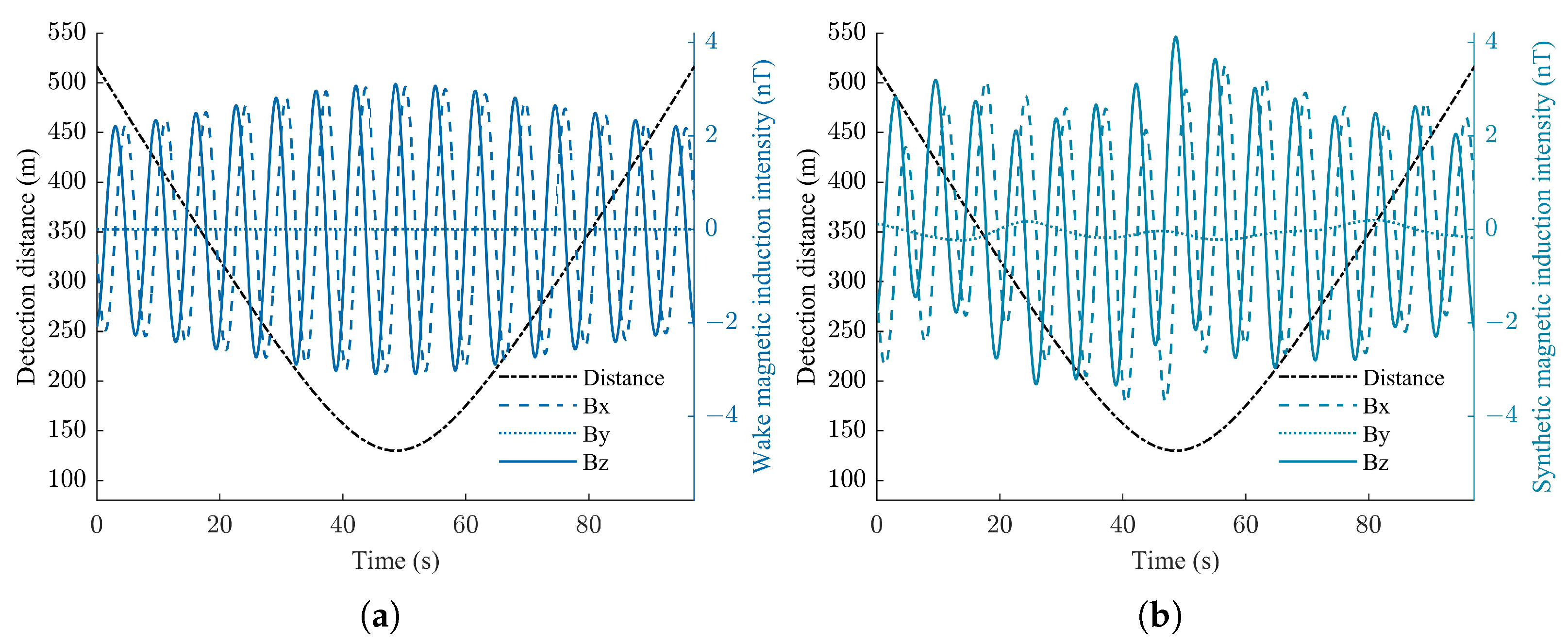
Figure 16 compares the influence of ocean waves on the wake magnetic field of the vehicle. The presence of ocean waves, as shown in
Figure 16b, introduces additional fluctuations in the wake magnetic vector field components: the
z-component exhibits the most significant fluctuations, with a variance standard deviation of 0.4478 nT, followed by the
x-component, with a standard deviation of 0.4202 nT, while the
y-component shows the smallest fluctuation among the three, with a standard deviation of only 0.1210 nT. Therefore, the influence on the
z-component appears to be most pronounced, as indicated by the larger amplitude fluctuations compared with the
x- and
y-components.
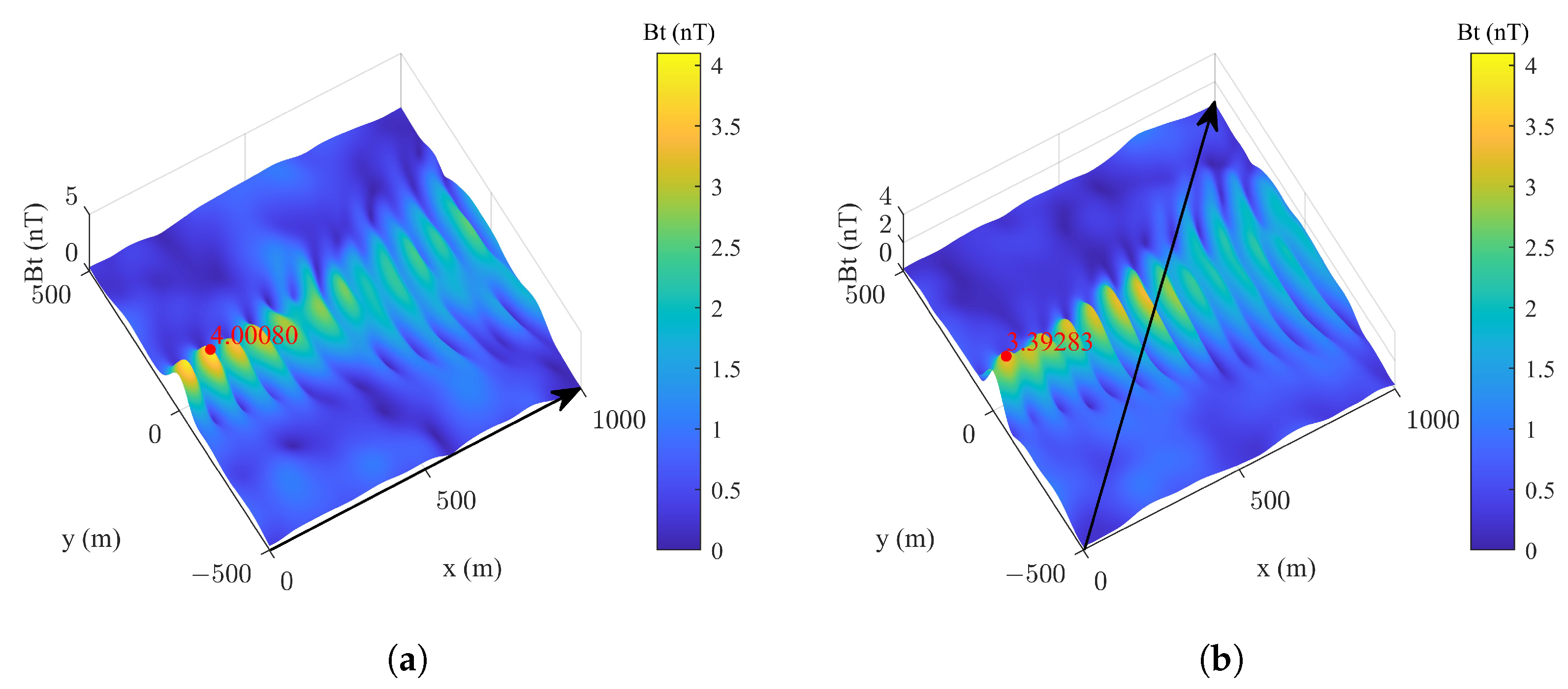
The synthetic wake and ocean wave magnetic fields on the detection plane when the wind speed is fixed at 10 kn and the wind direction is set to different angles are superimposed, as shown in
Figure 17. As the wind direction changes, the pattern and intensity of the magnetic field distribution also shift, indicating that wind direction significantly influences the magnetic field’s spatial characteristics. The wake magnetic field appears to be more intense and concentrated along the wind direction, which is particularly noticeable when the latter is 0°. By comparison, when the wind direction is 45°, the magnetic field shows a decrease in intensity. This suggests that the alignment of the wind direction with the vehicle’s wake symmetry axis (refer to
Figure 4) increases the intensity of the synthetic magnetic field.
3.3.2. Influence of Seawater Electrical Conductivity Changes at Different Geographical Locations
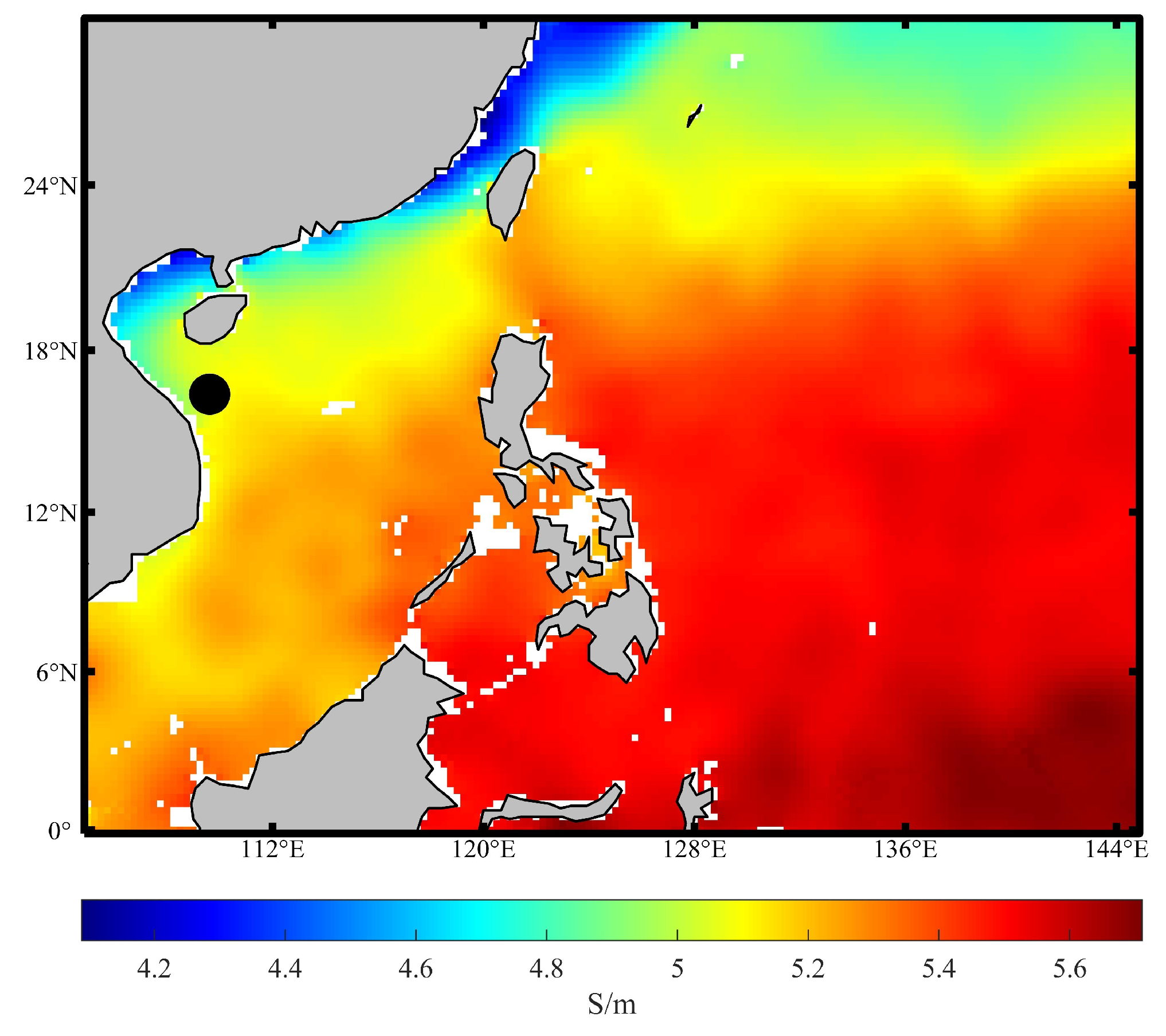
An underwater vehicle’s radiated magnetic field is influenced not only by ocean waves but also by seawater electrical conductivity. The distribution map of seawater electrical conductivity in a specific area (105°–145° E and 0°–30° N) is shown in
Figure 18, with the sea depth set to 10 m. The map illustrates that electrical conductivity generally increases as latitude increases, transitioning from lower values (indicated by blue) near the equator to higher values (indicated by red) towards the northern part of the map. Similarly, there is a gradient of conductivity with longitude, with values increasing from west to east. This suggests that the geographical location significantly affects seawater conductivity, which in turn can influence the characteristics of magnetic fields generated by underwater vehicles when sailing in different sea areas.
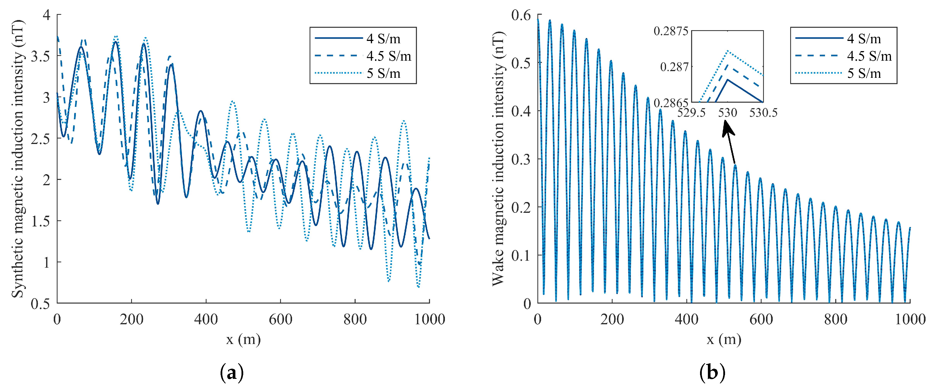
The influence of different seawater electrical conductivity values along the detection path on the synthetic wake and ocean wave magnetic fields is compared in
Figure 19a. Initially, up to approximately 400 m along the
x-axis, the wake magnetic field is dominant, characterized by pronounced magnetic field fluctuations. Beyond this point, the ocean wave magnetic field becomes more prominent as the wake magnetic field diminishes, resulting in reduced amplitude fluctuations. Additionally, an increase in seawater conductivity slightly enhances the wake magnetic field.
Since ocean waves exhibit random motion, the effect of seawater conductivity on their magnetic field does not follow a fixed pattern. In order to study the influence law of electrical conductivity on magnetic fields more accurately, only the wake magnetic field along the detection path is simulated, as shown in
Figure 19b. It is evident that the magnetic induction intensity increases with the increase in conductivity. However, the amplitude of the magnetic field fluctuations remains relatively constant across different conductivity levels, indicating that while conductivity influences the overall magnetic induction intensity, it does not significantly alter the characteristic oscillation pattern of the wake magnetic field. A comprehensive comparative analysis of the wake magnetic field’s maximum values at different latitudes sampled at 5° intervals from 0°–30° N and longitude fixed at 140° E is detailed in
Table 4.
Table 4 reveals a consistent pattern: for every 5° increase in latitude, there is a noticeable decrease in conductivity, from 5.360405 S/m to 4.742754 S/m. Concurrently, the wake magnetic field intensity also diminishes, dropping from 0.553892 nT to 0.477194 nT. Therefore, for every 5° increase in latitude, the electrical conductivity decreases by approximately 0.097 S/m, and the wake magnetic field intensity decreases by about 0.014 nT. These data provide a clear quantitative depiction of how both seawater conductivity and the associated wake magnetic field are affected by changes in latitude.
4. Discussion
In
Section 2, we presented the magnetic anomaly field of an underwater vehicle and the comprehensive characteristics of the wake magnetic field and, in
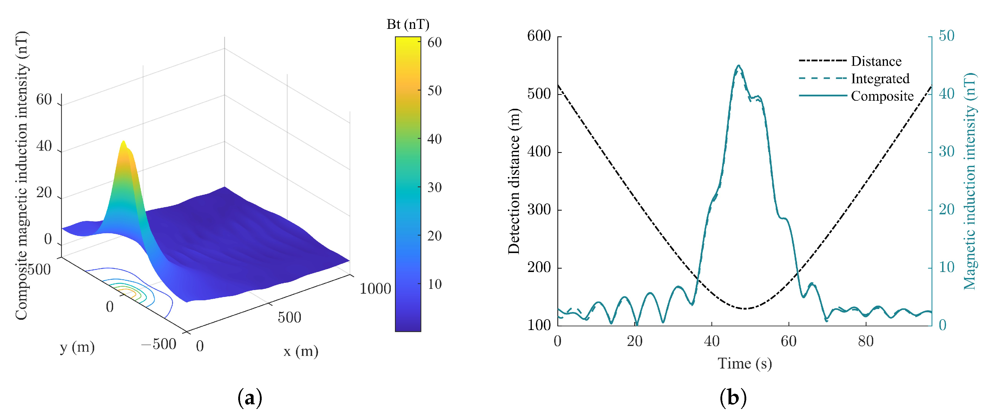
Section 3, the characteristics of the wave magnetic field and its influence on the wake magnetic field. Therefore, the composite magnetic field measured on the detection plane is obtained by combining the magnetic anomaly, wake, and ocean wave magnetic fields, as shown in
Figure 20. Compared with the condition of a calm sea surface, it can be seen that ocean waves slightly alter the shape and distribution of the magnetic field around the vehicle, indicating that wave conditions can modulate the magnetic signatures detected by sensors. Notably, the standard deviation in fluctuations in both the composite and integrated magnetic fields is approximately 0.3741 nT, as illustrated in
Figure 20b, indicating that the impact of ocean waves on the magnetic field of the vehicle is relatively minor under sea state Code 3. However, as the sea condition level increases, the influence of waves on the magnetic field generated by the underwater vehicle becomes increasingly significant.
Finally, the effects of vehicle motion and marine environmental parameters on magnetic fields are compared in
Table 5, where the arrows indicate the direction of the influence of each parameter on the magnetic field. An upward arrow (↑) indicates a positive correlation between the parameter and the magnetic field intensity, meaning that the intensity generally increases with an increase in the parameter, while a downward arrow (↓) signifies a negative correlation; the arrow combination (↕) signifies that the effect of the parameter on the magnetic field is not straightforwardly positive or negative, while parameters without arrows have no significant effect on the corresponding magnetic field.
According to
Table 5, the specific influence of each parameter on different magnetic fields can be obtained as follows:
Magnetic anomaly field: The intensity is influenced by the vehicle’s course and diving depth, where a smaller angle between the vehicle’s course and the geomagnetic field direction increases the intensity. Marine parameters do not directly affect it;
Wake magnetic field: The intensity is significantly affected by the vehicle’s speed and diving depth, where higher speeds and smaller depths enhance the wake field’s intensity. Additionally, seawater conductivity has a positive impact, reducing the field intensity as conductivity decreases;
Ocean wave magnetic field: The intensity of this field is primarily affected by wind speed and direction, where higher wind speeds and specific wind directions that align with the geomagnetic field increase the intensity;
Composite magnetic field: The intensity rises with vehicle speed and wind speed but falls with increased diving depth. Additionally, the field is negatively impacted by smaller angles between the vehicle’s course and the geomagnetic field, as well as between the wind direction and the geomagnetic field.
5. Conclusions
In conclusion, this study thoroughly examined the composite magnetic fields of underwater vehicles under ocean wave conditions, combining the modeling of the magnetic anomaly field, the wake magnetic field, and the ocean wave magnetic field. Simulation results reveal that a vehicle’s motion parameters, including navigation speed, course, and diving depth, significantly affect the distribution of its magnetic field. Additionally, marine environmental parameters such as wind speed, wind direction, and seawater electrical conductivity play pivotal roles in shaping the composite magnetic field. This study contributes significantly to a profound understanding of the magnetic fields generated by underwater vehicles as they navigate through ocean waves, with the following being unique contributions to this field:
The exploration of the relationship between vehicle speed and the magnetic anomaly field provides a novel perspective not previously addressed;
The analysis of how the vehicle’s course influences magnetic fields offers novel insights into underwater vehicle dynamics;
Examining the impact of wind parameters, including wind direction and speed, on ocean wave magnetic fields adds new dimensions to our understanding of the influences of the ocean environment;
The investigation into the spatiotemporal characteristics of composite magnetic fields under various parameters reveals details previously unstated in other research works.
Our findings underscore the complexity and uniqueness of the magnetic fields under study. Future research will focus on refining the mathematical model by considering the magnetic fields associated with tides and currents in seawater, and exploring additional parameters to better understand the complex interactions between underwater vehicles and the ocean environment.
