Article

Verification of Interaction Between Cl Erosion and Carbonation in Marine Concrete

by
Maohua Zhang
1,*,
Lin Du
2 and
Ronghua Xu
3
1
School of Future Cities, University of Science and Technology Beijing, Beijing 100083, China
2
China Railway Fifth Survey and Design Institute Group Co., Ltd., Beijing 102625, China
3
School of Civil Engineering, Northeast Forestry University, Harbin 150040, China
*
Author to whom correspondence should be addressed.
J. Mar. Sci. Eng. 2025, 13(1), 97; https://doi.org/10.3390/jmse13010097
Submission received: 18 November 2024 / Revised: 9 December 2024 / Accepted: 22 December 2024 / Published: 7 January 2025
(This article belongs to the Section Ocean Engineering)

Abstract

:
Marine concrete frequently experiences performance degradation due to the combined effects of chloride ion (Cl) erosion and carbonation. While many studies have examined the separate effects of Cl erosion and carbonation, their combined impact on concrete is still debated. Investigating the interaction mechanisms between Cl erosion and carbonation is crucial for improving the durability of concrete structures. This study utilizes a method where concrete specimens are immersed in artificial seawater with NaCl concentrations of 5%, 10%, and 15% prior to carbonation, with carbonation depth serving as a key indicator for analyzing the impact of Cl erosion on carbonation. Both carbonation-treated and standard concrete specimens are immersed in 5% artificial seawater to evaluate the impact of carbonation on chloride erosion, with the free chloride content in the concrete serving as the assessment criterion. Scanning electron microscopy (SEM) is employed to examine the microstructure of the concrete, elucidating the interplay between Cl erosion and carbonation. This study reveals that (1) Cl erosion hinders concrete carbonation as NaCl crystals and Friedel’s salt in the pores limit CO2 penetration, with this effect intensifying at higher artificial seawater concentrations; (2) carbonation has a dual impact on Cl erosion: in fully carbonated areas, carbonation products block pores and restrict Cl diffusion, while at the interface between carbonated and non-carbonated zones, carbonation depletes Ca(OH)2, reducing Cl binding capacity, increasing free Cl content, and promoting Cl diffusion.

1. Introduction

The ongoing economic growth and technological progress have led to the construction and utilization of various marine engineering projects, including harbors, piers, sea-crossing bridges, underwater tunnels, and offshore drilling platforms. Marine concrete structures play a critical role in these projects, yet the complexity of the marine environment poses significant challenges to their long-term durability [1,2]. Chloride erosion and carbonation are key degradation mechanisms that compromise the durability of marine concrete. Chloride ion penetration from seawater or air into concrete causes steel reinforcement corrosion, compromising load-bearing capacity and structural stability. The expansion of corroded steel induces cracking and spalling of the concrete, ultimately threatening structural safety [3,4]. Carbonation happens when atmospheric CO2 reacts with Ca(OH)2 in concrete, producing CaCO3 and reducing alkalinity. The decrease in pH reduces steel passivation, increasing its vulnerability to Cl corrosion [5,6,7]. These two degradation processes often occur simultaneously in marine environments, creating complex and profound impacts on concrete durability.
Numerous studies have investigated concrete durability under the combined effects of chloride erosion and carbonation, yet disagreements persist. Some researchers argue that the CaCO3 formed during carbonation increases the concrete’s density, effectively slowing Cl diffusion. For example, Ihekwaba et al. [8] demonstrated that carbonation lowers the pH, reducing the Cl binding capacity and delaying its diffusion. Tumidajski et al. [9] demonstrated that CO2 notably decreased Cl diffusion in concrete subjected to mixed salt solutions. Puatatsananon et al. [10] observed that alternating chloride immersion and carbonation decreased pore space, thus inhibiting Cl diffusion. Similarly, Zheng [11] reported that carbonation products filled concrete pores, enhancing density and reducing Cl diffusion coefficients. Chindaprasirt et al. [12] also found that CO2 slowed the penetration and diffusion of Cl in cement mortar, while Goni et al. [13] demonstrated that although Friedel’s salt decomposes during accelerated carbonation tests, the free Cl content remains largely unchanged, indicating that carbonation impedes Cl diffusion. Hassnan et al. [14] demonstrated that carbonation significantly reduces the Cl binding capacity of cement paste, thereby inhibiting Cl diffusion.
Conversely, other researchers argue that although carbonation reduces the total pore volume in concrete, it increases the most probable pore diameter, thereby enhancing pore connectivity and making Cl penetration easier. Yuan et al. [15] investigated carbonation’s impact on chloride diffusion, revealing that it elevates free chloride levels in concrete, thereby increasing the diffusion coefficient and diminishing resistance to chloride erosion. Dang et al. [16] reported that under accelerated carbonation conditions, the presence of Cl decreased concrete’s chloride binding capacity while improving its resistance to carbonation and reducing porosity. According to Papadakis et al. [17], carbonation enhances the breakdown of Friedel’s salt, thereby facilitating Cl penetration. Suryavanshi et al. [18] observed that carbonation released chloride from Friedel’s salt into pore solutions, raising the risk of steel corrosion. Oh et al. [19] reported that the combination of carbonation and Cl erosion resulted in more pronounced Cl ingress, while Niu et al. [20] found that carbonation increased the rate of Cl penetration. Jin et al. [21] also showed that Cl content and diffusion coefficients increased with carbonation time, and Sun [22] confirmed that carbonation accelerates Cl diffusion. Wan et al. [23] suggested that carbonation altered the pore structure of concrete, increasing the Cl diffusion coefficient. Recent studies [24,25] further indicate that while carbonation decreases the overall porosity of concrete, it increases the most probable pore diameter, facilitating Cl ingress.
Compared to studies on the impact of carbonation on Cl erosion, research on how Cl affects carbonation is less common. Liu et al. [26] demonstrated, using X-ray and mercury intrusion porosimetry, that carbonation in cement paste is enhanced by higher water−cement ratios and extended carbonation exposure, while it diminishes with increased Cl content. Qiu et al. [27] observed that the presence of Cl reduced the carbonation depth and pH of concrete.
Research shows that understanding the durability of concrete in marine and atmospheric environments is of great importance. Despite numerous experimental studies, the interaction between Cl erosion and carbonation in concrete remains inconclusive. Most studies focus on the effects of carbonation on Cl erosion, while the reverse—Cl erosion’s influence on carbonation—has been less thoroughly explored. While some experimental findings reveal consistent trends, the results remain scattered and often contradictory. Overall, the combined effects of carbonation and Cl erosion are complex, exhibiting both positive and negative influences that are significantly affected by experimental variables. Thus, the interaction between Cl erosion and carbonation is not yet fully understood, especially in marine concrete subjected to long-term exposure in harsh marine environments. Further investigation is urgently needed to understand their coupling mechanisms more comprehensively.
This study systematically examines the interaction mechanisms of chloride erosion and carbonation in marine concrete through experiments simulating marine environments. This research focus on analyzing the effects of different concentrations of sodium chloride (NaCl) solution on carbonation depth, as well as how carbonation influences Cl diffusion. The microstructural analysis investigates alterations in the concrete pore structure and chemical reactions due to the combined effects of Cl erosion and carbonation. By thoroughly exploring their mutual influences, this study aims to provide a scientific basis for the design and durability assessment of marine concrete, particularly for key infrastructures such as bridges, piers, and seawalls exposed to long-term marine environments. Enhancing the resistance of marine concrete to both Cl erosion and carbonation is critical for ensuring structural safety and prolonging service life. The results offer valuable insights for optimizing concrete mix designs, construction techniques, and maintenance strategies, providing theoretical support for the durability design of marine engineering projects.

2. Experimental Overview

2.1. Experimental Materials

2.1.1. Cement

In this study, ordinary Portland cement P.O 42.5, produced by Harbin Cement Factory, was used. The quality of the cement complies with the Chinese standard [28]. Table 1 and Table 2 present the chemical composition and performance parameters of the cement.

2.1.2. Aggregates

Coarse Aggregate: This study utilized continuously graded basalt crushed stone as coarse aggregate, with a particle size range of 5–31.5 mm. Performance indicators were assessed following the standard [29]. These indicators are listed in Table 3.
Fine Aggregate: This study utilized well-graded river sand as the fine aggregate. A sieve analysis following the sandard for the fineness modulus of the medium sand to be 2.57 [30].

2.1.3. Water-Reducing Admixture

The admixture selected for this study is a water-reducing agent, which refers to a concrete admixture that reduces the amount of mixing water while maintaining the same concrete slump. When added to concrete, the water-reducing agent disperses cement particles and improves workability. In this study, FDN-type naphthalene-based superplasticizer, produced by Harbin Aoxiang Admixture Company (Harbin, China), was used. The main performance indicators of the superplasticizer are listed in Table 4.

2.1.4. NaCl Solution

This study prepared NaCl solutions at concentrations of 5%, 10%, and 15% to simulate artificial seawater.
Due to the long-term nature of concrete durability tests, time constraints often result in weak observable effects under low concentration conditions. Therefore, guided by the principles of indoor accelerated testing, higher concentrations of NaCl solution were used to expedite the chloride ion erosion process.

2.1.5. Concrete Mix Proportion

According to the standard [31], marine engineering demands high durability, classified as III-C. This study selected C45 grade concrete, expected to last 100 years, to ensure reliability in chloride-rich conditions. The mix design included a water-to-cement ratio of 0.45, a sand ratio of 33%, and a superplasticizer dosage of 0.25% relative to the cement content. The detailed concrete mix proportions are shown in Table 5.

2.2. Experimental Program

2.2.1. Validation Test for the Interaction of Chloride Erosion and Carbonation Effect of Chloride Erosion on Carbonation

Effect of Chloride Erosion on Carbonation

Concrete specimens measuring 100 mm × 100 mm × 400 mm were cast and cured in a standard chamber for 26 days. The specimens were categorized into four groups: W + C, Cl-5 + C, Cl-10 + C, and Cl-15 + C. W + C represent the specimens immersed in water prior to carbonation, while Cl-5 + C, Cl-10 + C, and Cl-15 + C represent the specimens immersed in 5%, 10%, and 15% NaCl solutions, respectively, prior to carbonation.
After 26 days of curing, the specimens were taken out of the chamber, wiped to eliminate surface moisture, and oven-dried at (80 ± 5) °C for 48 h. The specimens were subsequently cooled to room temperature in a dry setting.
The specimens, after cooling, were submerged in NaCl solution for 28 days. Post-immersion, the specimens were oven-dried at 80 ± 5 °C for 6 h before being transferred to a carbonation chamber. The chamber’s carbonation conditions were established with a CO2 concentration of 20% ± 3%, a temperature of 20 ± 2 °C, and a relative humidity of 70% ± 5%. Carbonation depths were assessed at intervals of 3, 7, 14, and 28 days. The average value was recorded from tests conducted on three specimens per condition. The immersion periods and the number of specimens are listed in Table 6.

Effect of Carbonation on Cl Erosion

Concrete specimens measuring 100 mm × 100 mm × 400 mm were cast and cured for 26 days in a standard curing room. The specimens were categorized into two groups: CCl and ACl. The CCl group consists of specimens carbonated prior to immersion in NaCl solution, whereas the ACl group includes specimens exposed to air under identical temperature and humidity conditions to the CCl group before being immersed in NaCl solution.
After 26 days of curing, the specimens were taken out of the standard curing room, wiped to remove surface water, and oven-dried at 80 ± 5 °C for 48 h. The specimens were cooled to room temperature in a dry environment after drying.
The CCl group specimens were carbonated in a standard carbonation chamber for 28 days. The ACL group specimens were exposed to identical temperature and humidity conditions in the air for 28 days. Afterward, all specimens were immersed in a 5% NaCl solution, and the chloride ion concentration was measured at 1, 2, 3, and 4 weeks. Two specimens from each group were tested, and the average chloride concentration was recorded. The curing time and specimen quantity are shown in Table 7.

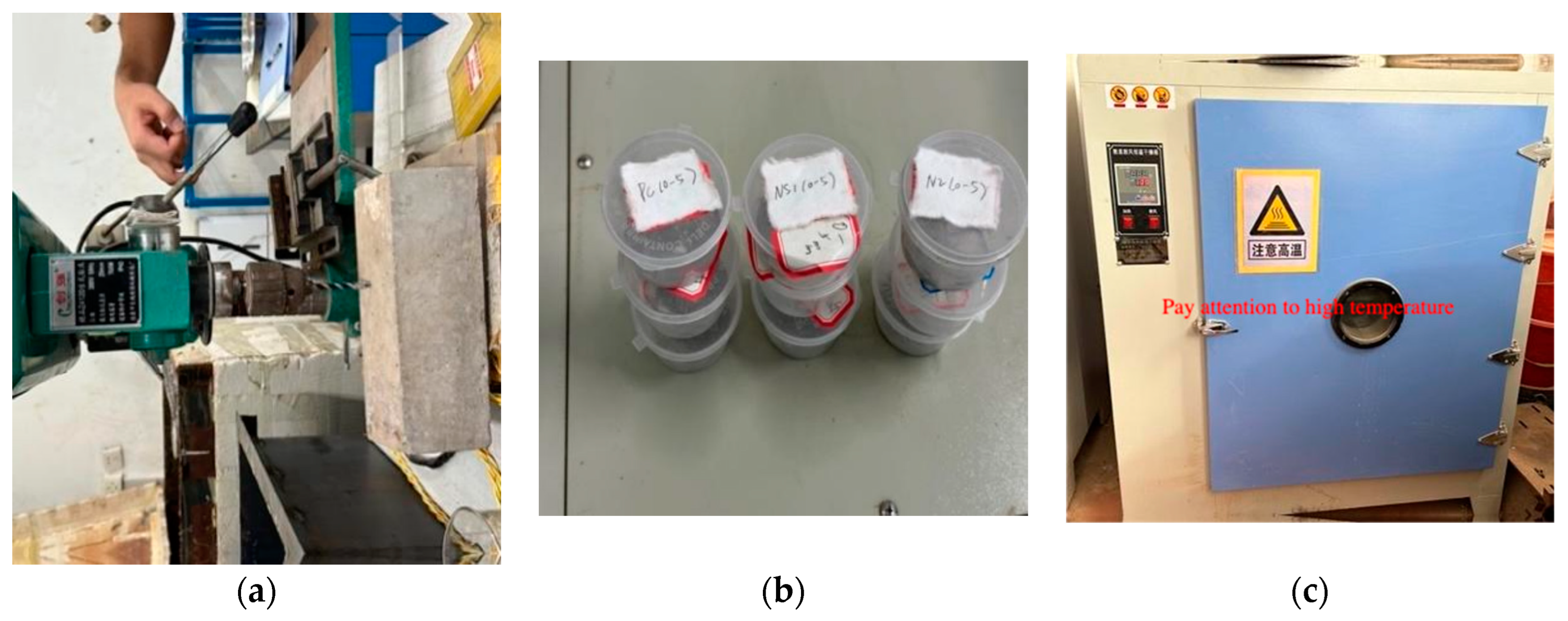
2.2.2. Experimental Testing IndicatorsFree Chloride Ion Content

Free Chloride Ion Content

Powder Sampling: Concrete specimens measuring 100 mm × 100 mm × 100 mm were utilized in this study. Each test group consisted of three specimens to facilitate powder sampling. A desktop drill was used to collect powder samples precisely from six sides of each specimen. Drill hole depths were categorized into intervals of 0–5 mm, 5–10 mm, 10–15 mm, 15–20 mm, and 20–25 mm. To ensure accuracy, 5 g of powder samples were collected from both the front and back faces of each cube, totaling 15 samples across five groups. The powder samples were sieved with a 0.63 mm mesh and dried at 105 ± 5 °C for 2 h. The powder was cooled to room temperature after drying to accurately measure the free chloride ion content. Figure 1 illustrates the procedure in detail.
Determination of Free Chloride (Cl): Following the standard [32], we assessed the free chloride (Cl) content in the samples from each group. The concentration of free Cl in concrete serves as a crucial reference indicator, reflecting the corrosion rate of the reinforcing steel. As the Cl content increases, the corrosion effect becomes more pronounced. Figure 2 illustrates the process of determining free Cl content, with the following specific operational steps:
(1)
Place 10 g of precisely measured dry material into a conical flask, add 100 milliliters of distilled water, and shake vigorously for 1 to 2 min. Allow the mixture to soak for 24 h to ensure complete dissolution of the material.
(2)
Filter the soaked powder using filter paper, then transfer 10 mL (V2) of the filtrate into a clean conical flask and add one drop of phenolphthalein, resulting in a pale pink color.
(3)
Add dilute sulfuric acid solution until the solution is colorless.
(4)
Add an appropriate amount of potassium chromate solution to the conical flask, resulting in a yellow color.
(5)
Quickly titrate with AgNO3 solution (V3) using a burette until the solution turns brick red. After completing the experiment, calculate the concentration of free Cl using Formula (1).
P = 0.03545 × C A g N O 3 × V 3 G V 2 / V 1 × 100 %
In the equation, P1 indicates the concentration of free Cl in the mortar (%); C A g N O 3 is the silver nitrate solution concentration (mol/L); G denotes the mortar sample mass (g); V1 is the volume of silver nitrate solution used per titration (mL); V2 represents the volume of extracted filtrate (mL); and V3 is the volume of silver nitrate solution used per determination (mL).

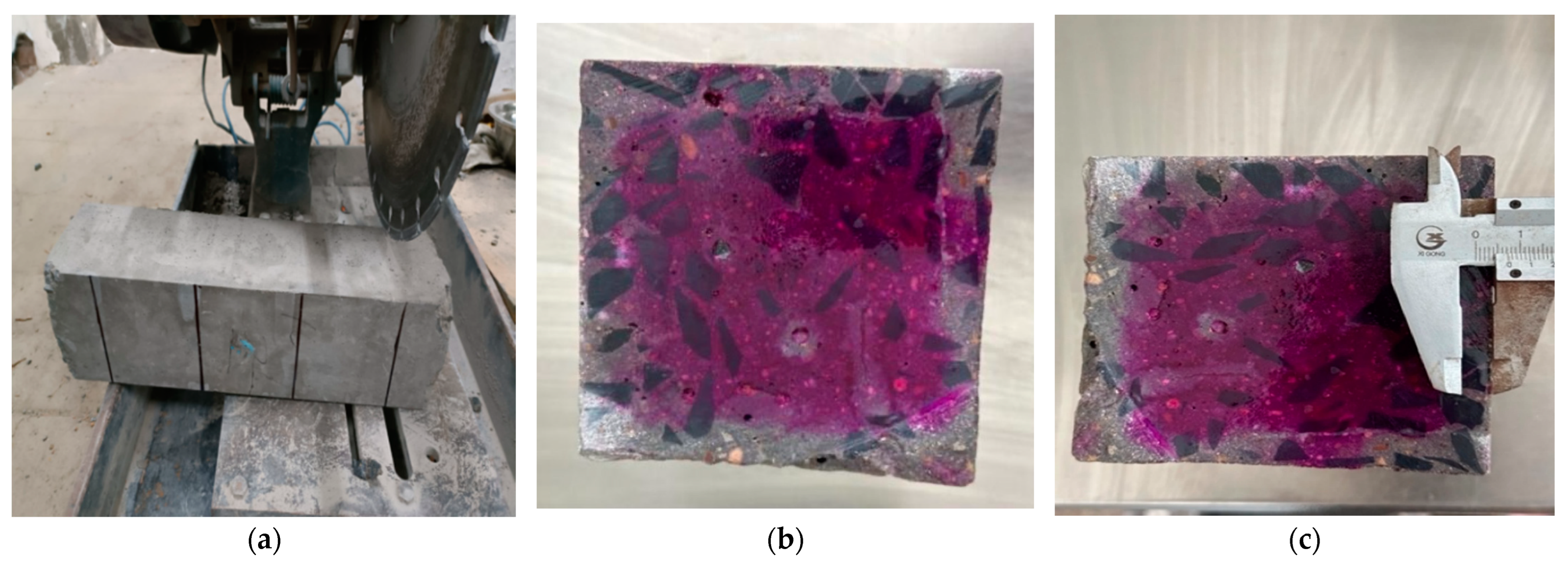
Carbonation Depth Measurement

In accordance with the standard [33], concrete specimens with dimensions of 100 mm × 100 mm × 400 mm were used in this study. Three specimens were tested in each group, and tests were conducted across different experimental groups. Upon reaching the designated carbonation age, the concrete specimens were cut perpendicular to pre-marked parallel lines using a cutting machine. A 1% phenolphthalein alcohol solution was then applied to the freshly cut surface. Starting from a marked point prior to carbonation, the carbonation depth was measured at intervals of 10 mm, for a total of 18 measurement points. The carbonation depth data from each group of specimens was collected, and the average value, accurate to 0.1 mm, was calculated to reflect the carbonation behavior of the concrete specimens at different carbonation ages. For detailed experimental steps, please refer to Figure 3.

3. Experimental Results and Analysis
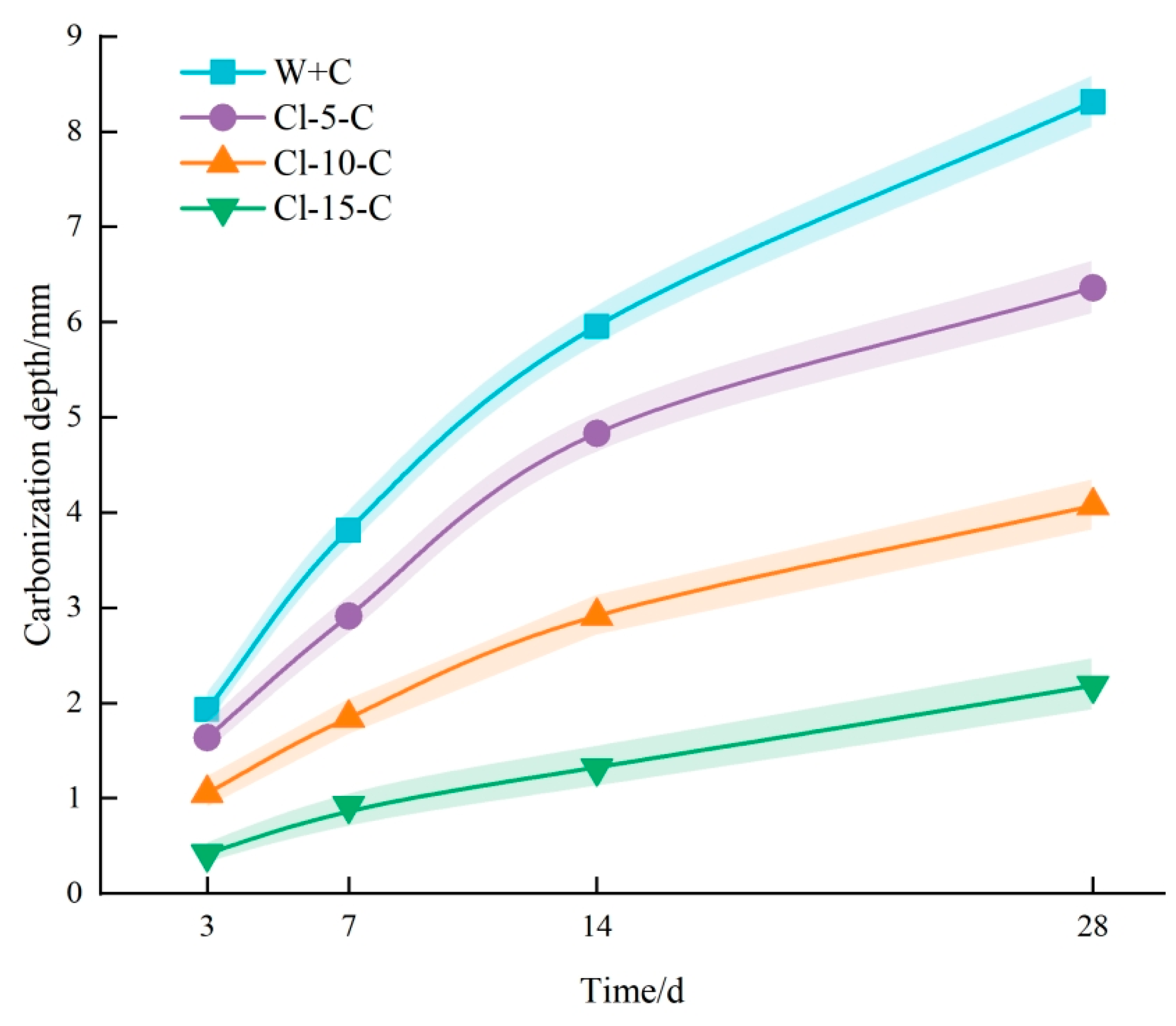
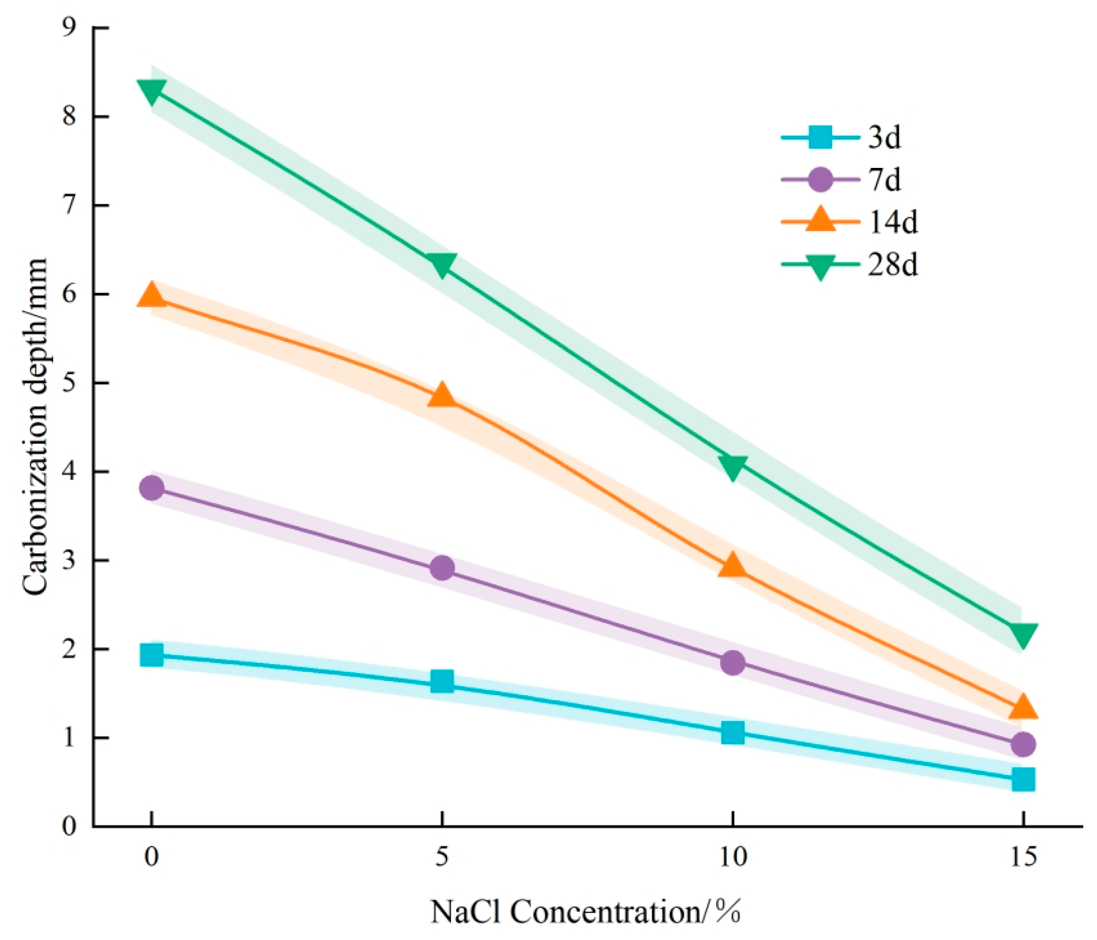
3.1. Effect of Cl Erosion on Carbonation

Figure 4 demonstrates that the carbonation depth of concrete progressively increases with age. However, following immersion in NaCl solution, all concrete groups exhibited varying degrees of reduction in carbonation depth. Notably, the carbonation depth of the Cl-15 + C group decreased by 72.54%, 75.65%, 77.82%, and 73.68% at ages 3, 7, 14, and 28 days, respectively, compared to the W + C group, highlighting a significant inhibitory effect. The Cl-10 + C group also demonstrated a substantial reduction in carbonation depth, while the Cl-5 + C group exhibited a more modest decline. Reductions of 15.03%, 23.56%, 18.82%, and 23.47% at respective ages demonstrate that chloride ion (Cl) erosion effectively inhibits concrete carbonation, with increased NaCl concentration enhancing this inhibitory effect.
Figure 5 illustrates the trend of concrete carbonation depth as a function of NaCl solution concentration. The experimental results indicate that, at various ages, the carbonation depth of concrete decreases progressively with increasing NaCl concentration, showing a significant negative correlation between carbonation depth and NaCl concentration. This suggests that higher concentrations of Cl corrosion exert an enhanced inhibitory effect on concrete carbonation. Notably, during the early stages on days 3 and 7, the curve exhibits a relatively shallow slope, whereas at later stages (14 and 28 days), the slope of the curve increases significantly. This indicates that Cl corrosion has a more pronounced inhibitory effect on carbonation in the later stages of concrete aging. The findings from this study highlight the significant impact of Cl corrosion on the suppression of concrete carbonation, especially in the later stages. Higher concentrations of NaCl solution were found to effectively delay the carbonation process, providing valuable insights for improving the durability of concrete.
To provide further statistical validation, we calculated the standard deviation (SD) and coefficient of variation (CV) for the carbonation depths at different ages and NaCl concentrations. For example, at 28 days, the SD for the carbonation depth in the Cl-15 solution was ±0.04 mm, while in the W + C group, it was ±0.06 mm. The corresponding CV values for Cl-15 at 28 days were 3.85%, compared to 6.48% for the W + C group. These calculations suggest that, in the presence of higher NaCl concentrations, the carbonation depth shows less variability, indicating a more consistent inhibition effect. The decreased SD and CV in the Cl-15 group further confirm the stabilizing and effective impact.
Scanning electron microscopy (SEM) was used to examine the microstructure of concrete specimens from the W + C and Cl-15 + C groups after testing to assess the impact of NaCl solution on concrete microstructure (see Figure 6 and Figure 7). Figure 6b and Figure 7b provide detailed views of the regions labeled ① and ② in Figure 6a and Figure 7a, respectively.
From Figure 6a, it is evident that the untreated concrete specimen contains prominent large pores, the majority of which form interconnected structures that compromise the durability of the concrete. In contrast, Figure 7a illustrates a significant reduction in internal porosity in the concrete treated with NaCl solution, with few large, interconnected pores remaining. This observation indicates that NaCl treatment substantially enhances the compactness of the concrete.
A comparison of Figure 6a and Figure 7a reveals that chloride (Cl) erosion exerts a pore-refining effect on the concrete microstructure. Following exposure to Cl, the previously large pores were considerably refined, resulting in an overall denser structure, which improves the concrete’s resistance to carbonation. Additionally, Figure 6b and Figure 7b highlight notable changes in the material morphology within the concrete. In Figure 7b, a substantial amount of flocculent hydration products is visible, which were not distinctly apparent in the untreated W + C group. The Cl-15 + C group (Figure 7b), subjected to Cl erosion, displays a considerable number of crystalline substances, primarily NaCl crystals and Friedel’s salt—both products of Cl intrusion. These crystals effectively fill the pores within the concrete, significantly reducing the number and size of interconnected pores, and further refining the pore structure. This refinement significantly improves the concrete’s carbonation resistance by hindering CO2 diffusion.
Chloride erosion improves concrete’s microstructure and compactness by refining pore structure and facilitating Friedel’s salt formation. The microstructural changes strongly indicate the long-term durability of concrete when exposed to chloride.
The integration of experimental results and microstructural images reveals that chloride erosion followed by carbonation densifies the concrete’s internal structure, hindering further carbonation. This can be attributed to two primary factors:
(1)
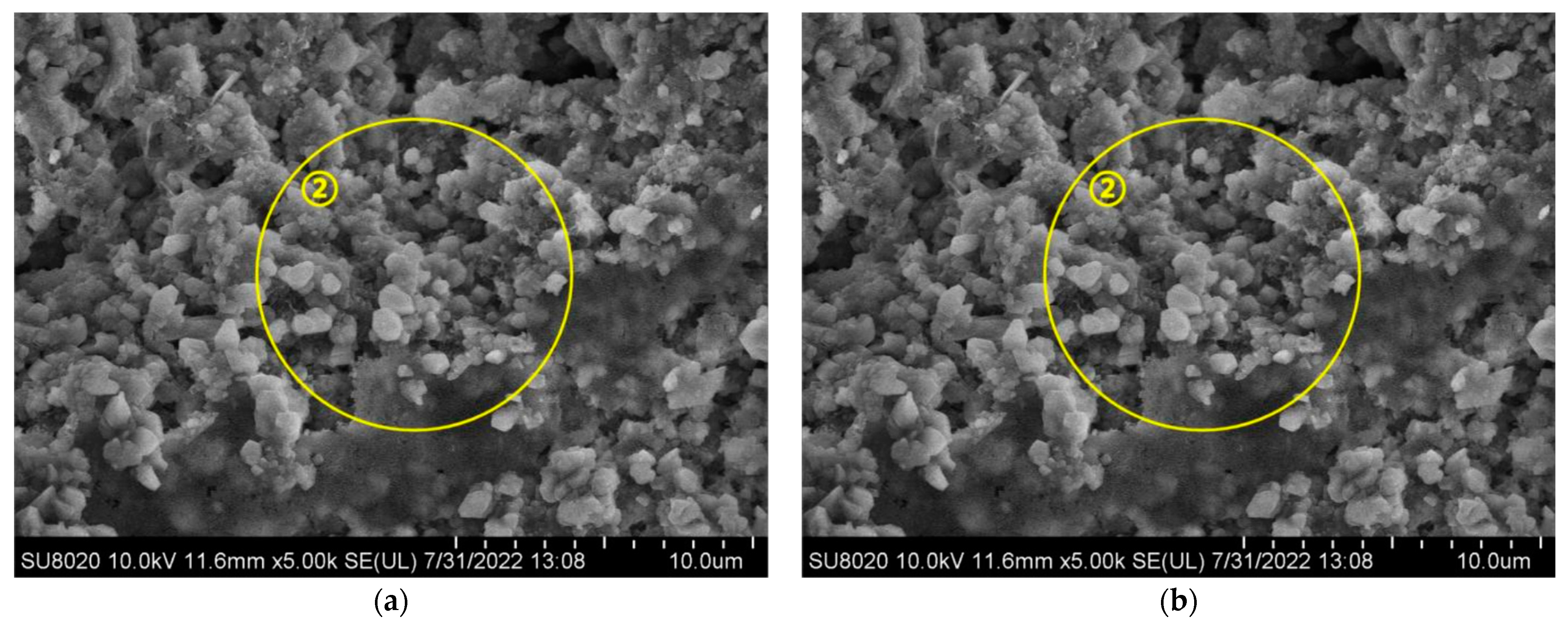
Physical Mechanism: During the experiment, concrete specimens were initially soaked in a NaCl solution, subsequently dried in an oven, and finally subjected to carbonation treatment. Following immersion in NaCl solution, the concrete stayed dry for a prolonged period, causing surface moisture to evaporate and chloride salts to crystallize and remain within the concrete’s pores. As drying continued, the accumulation of chloride salt crystals gradually filled the internal pores of the concrete [34]. In practical engineering environments, this physical mechanism predominantly occurs in coastal tidal zones and splash zones. Concrete structures in these areas frequently undergo cycles of wetting and drying, with chloride salts infiltrating the concrete from seawater. As moisture evaporates during the drying phase, chloride salt crystals remain in the pores, resulting in gradual accumulation over multiple cycles in the surface pores. This accumulation effectively fills the concrete’s pores and reduces pore connectivity, thereby hindering further CO2 intrusion [35]. This phenomenon is one of the primary reasons for the less pronounced carbonation effects observed in concrete structures situated in coastal tidal and splash zones [36,37].
(2)
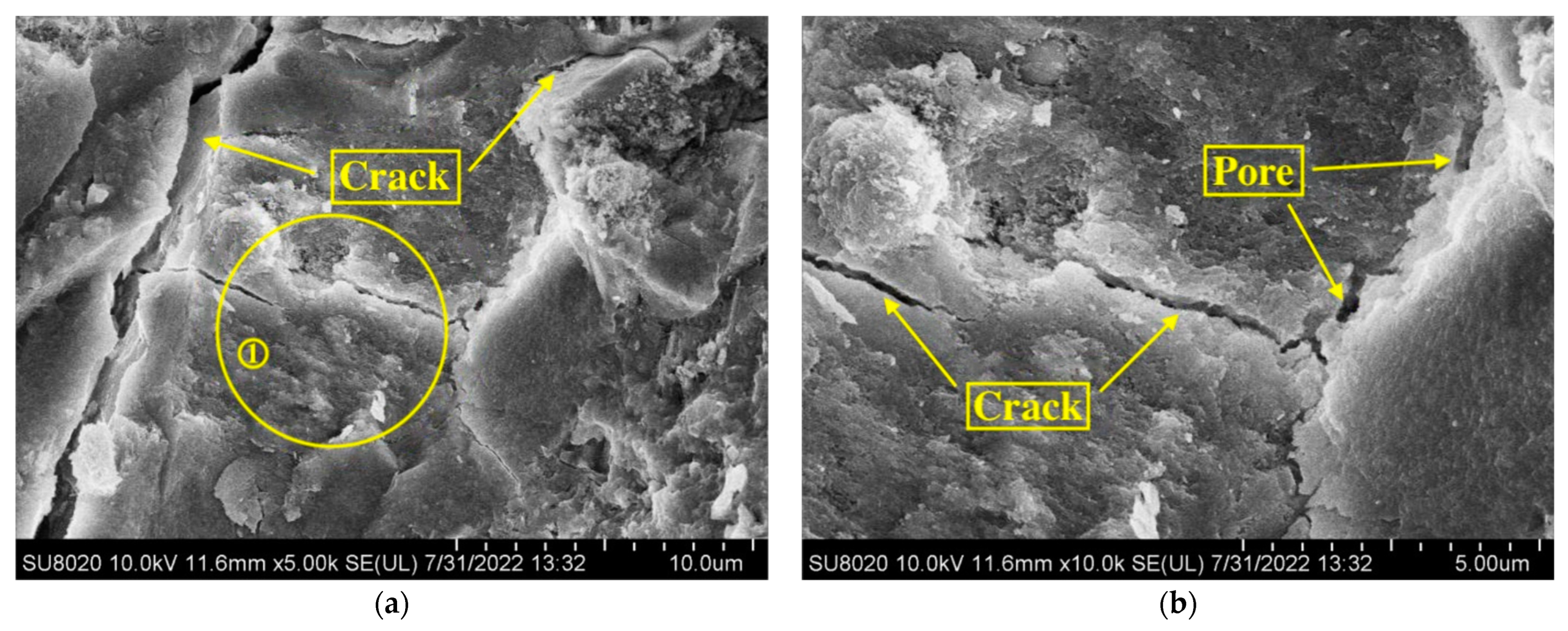
Chemical Mechanism: Upon entering the concrete, Cl ions can follow three main pathways [38]. Initially, Cl chemically interacts with cement hydration products to produce Friedel’s salt, a process known as the chemical binding of Cl. Second, Cl can be physically adsorbed onto the surface of calcium silicate hydrate (C-S-H) gel. Third, Cl can exist freely within the concrete’s pore solution, referred to as free Cl [39]. The presence of Friedel’s salt in the pores refines the pore structure by decreasing the number and size of interconnected pores, thereby improving the concrete’s compactness [40]. The densification of the structure obstructs CO2 ingress and diffusion, thereby slowing down the carbonation reaction [41].
In summary, the combined effects of Cl physical accumulation and chemical reaction significantly enhance concrete’s pore structure, thereby increasing its carbonation resistance. This finding provides important theoretical support for enhancing the durability of concrete structures in coastal environments.

3.2. The Effect of Carbonation on Chloride Ingress

The carbonation depth of the CCl group concrete was measured to be 8.3 mm before immersion. Figure 8 shows the distribution of free Cl content in both the ACl and CCl groups after immersion in a NaCl solution. The findings show that as drilling depth increases, the free Cl content in both groups progressively declines until it stabilizes. At identical drilling depths and curing periods, the CCl group consistently exhibited lower free Cl content compared to the non-carbonated ACl group. In the 0–10 mm zone from the concrete surface, a significant difference in free Cl concentration was observed between the two groups, with the CCl group exhibiting a notably lower free Cl content following carbonation. This region corresponds with the fully carbonated zone, suggesting that carbonation effectively hinders Cl diffusion into the interior of the concrete [37].
In the 10–15 mm range, the disparity in free Cl content between the CCl and ACl groups decreases quickly, with the CCl group exhibiting higher free Cl levels than the ACl group. This region roughly corresponds to the front of the partially carbonated zone. The underlying reason for this is that the concrete’s capacity to bind Cl can be described by Equation (2) [21]:
C 4 A H 6 + C a ( O H ) 2 + N a C l + H 2 O C 3 A · C a C l 2   · 10 H 2 O + N a O H
In the fully carbonated zone, carbonation depletes Ca(OH)2, which diminishes Friedel’s salt formation from the Ca(OH)2 and NaCl reaction, thus weakening the concrete’s Cl binding capacity. For a constant total Cl ingress, the carbonated zone exhibits a decrease in bound Cl content and a corresponding increase in free Cl content. This results in an increased Cl concentration gradient between the carbonated and non-carbonated zones. The gradient causes free Cl to move from the carbonated zone to the non-carbonated zone [42]. At the interface between carbonated and non-carbonated zones, particularly at the front of the partially carbonated zone, the free Cl-content in the CCl group exceeds that of the ACl group. In the 15–30 mm range, both groups exhibit minimal differences in free Cl content, as this region is within the non-carbonated zone where carbonation has negligible influence. In this region, Cl distribution follows a simple diffusion pattern, resulting in similar free Cl content between the two groups [43].
To enhance the statistical reliability of these findings, the standard deviation (SD) and coefficient of variation (CV) of the free Cl content within each depth range were calculated. For instance, in the 0–10 mm zone, the SD of free Cl content in the CCl group was ±0.02, while in the ACl group, it was ±0.04, with corresponding CV values of 3.75% and 6.72%, respectively. These results suggest that the variation in free Cl content was smaller in the CCl group, particularly in the fully carbonated zone, which further supports the conclusion that carbonation inhibits the diffusion of Cl. In the 10–15 mm zone, the SD for the CCl group increased to ±0.05, with a CV of 9.21%, indicating that the behavior of Cl in the partially carbonated region, where migration occurs, is more complex. These statistical measures underscore the effectiveness of carbonation in modifying the distribution of Cl within concrete and enhancing its resistance to chloride ion ingress.
Figure 9 presents the free Cl content in the concrete of the ACl and CCl groups at different ages. The data show that, as the age increases, the free Cl content in concrete gradually rises. At the same age and drilling depth, the coefficient of variation (CV) for the ACl group is generally higher, especially in the 0–5 mm drilling depth, indicating greater variation in free Cl content for the ACl group. In contrast, the CV for the CCl group is lower, particularly in the carbonated region, suggesting that carbonation significantly enhances the concrete’s resistance to Cl ingress, reducing the free Cl content. A larger difference in free Cl content between the ACl and CCl groups was observed at drilling depths of 0–5 mm and 5–10 mm. The one-way analysis of variance (ANOVA) results indicate a significant difference in free Cl content between the two groups (p < 0.05). However, as the drilling depth increased, the difference in free Cl content between the two groups decreased. This phenomenon can be attributed to the fact that the CCl group reached a carbonation depth of 8.3 mm after 28 days, with the 0–5 mm and 5–10 mm drilling regions located within the fully carbonated zone, where carbonation significantly affected the free Cl content. As the drilling depth increased, the Cl diffusion within the concrete became less influenced by carbonation, resulting in a reduced difference in free Cl content [44].
The diffusion of chloride ions in concrete is governed by Fick’s second law, expressed as follows:
c t = D 2 c x 2
where C represents the Cl concentration (%), t is the diffusion time (s), D is the Cl diffusion coefficient (mm2·s−1), and x is the distance from the concrete surface (mm). When t = 0, x > 0, c = c0; When x = 0, t > 0, c = cs. Thus, the theoretical model for Cl diffusion in concrete can be expressed as:
c = c 0 + c s c 0 1 e r f x 2 D t
where c0 represents the initial chloride concentration within the concrete (%), cs denotes the chloride concentration at the exposed concrete surface (%), and erf stands for the error function.
By substituting the free Cl contents at various depths for both the ACl and CCl groups into Equation (4) and using MATLAB 7.0 for curve fitting, the Cl diffusion coefficients for both groups at different curing ages were determined, as shown in Table 7. The results indicate that at all curing ages, the Cl diffusion coefficient for the carbonated CCl group is consistently lower than that of the non-carbonated ACl group. The reduction is due to CaCO3 formation during carbonation, which fills concrete pores and micro-cracks, hindering Cl ingress.
Further analysis was conducted by substituting the free Cl content at different depths for both groups into Equation (4) and performing a fitting analysis using MATLAB. The resulting Cl diffusion coefficients for both groups at various curing ages are presented in Table 8. The findings confirm that across all age periods, the Cl diffusion coefficient for the carbonated CCl group remains lower than that of the non-carbonated ACl group. This trend can be attributed to the CaCO3 produced during carbonation, which significantly fills the internal pores and micro-cracks of the concrete, effectively reducing Cl penetration. Consequently, the carbonation process enhances the concrete’s resistance to chloride ions.
This study utilized scanning electron microscopy (SEM) to analyze the microstructural morphology of the ACl and CCl groups, aiming to further explore carbonation’s effect on concrete’s chloride (Cl) resistance. The results are presented in Figure 10 and Figure 11, which display magnified micrographs of the concrete samples.
Figure 10 reveals that the ACl group exhibits a lower degree of densification, characterized by significant cracks and voids, which increases its susceptibility to Cl ingress. In contrast, the CCl group, illustrated in Figure 11, also shows defects such as porosity; however, the spherical CaCO3 produced during the carbonation process acts as an insoluble calcium salt. This reaction leads to an expansion relative to the original products, partially filling the voids and micro-cracks within the concrete. Consequently, this effect significantly enhances the internal densification of the concrete and reduces its porosity, thereby mitigating the corrosive impact of Cl on the material to some extent.
In summary, the impact of carbonation on Cl ingress exhibits a dual effect, characterized by both obstructive and facilitative mechanisms. The obstructive effect is predominantly observed in the fully carbonated zone, where the CaCO3 generated during carbonation effectively fills the pores within the concrete, enhancing its density and significantly impeding Cl diffusion. In contrast, the facilitative effect is primarily evident at the interface between the carbonated and uncarbonated zones.
The carbonation process significantly consumes Ca(OH)2 in cementitious materials, diminishing the concrete’s capacity to bind Cl (as shown in Equation (3)). This reduction promotes an increased influx of free Cl into the concrete. The pH reduction in the carbonated zone’s pore solution further destabilizes Friedel’s salt. CO2 may also react with Friedel’s salt, as illustrated in Equation (5) [45,46]:
3 C a O · A l 2 O 3 · C a C l 2 · 10 H 2 O + 3 C O 2 3 C a C O 3 + 2 A l ( O H ) 3 + C a C l 2 + H 2 O
This reaction releases bound Cl as free Cl, further diminishing the concrete’s capacity to retain Cl. The combination of these processes at the boundary between the carbonated and uncarbonated zones results in the accumulation of free Cl.

4. Conclusions

The interplay between chloride ion (Cl) erosion and carbonation in concrete is a subject of ongoing debate. This study experimentally validated the interactions between Cl erosion and carbonation, resulting in the following conclusions.
(1)
After Cl erosion, the carbonation depth of concrete notably reduced across all ages. Additionally, the reduction in carbonation depth became more pronounced with increasing concentrations of the NaCl solution. Microscopic examinations revealed the formation of crystalline substances within the concrete, which filled the pores and impeded further CO2 ingress. This indicates that Cl erosion acts to inhibit carbonation.
(2)
The inhibition of carbonation by Cl erosion can be attributed to the accumulation of NaCl crystals within the concrete pores as surface water evaporates after immersion in the NaCl solution. Furthermore, the expansive Friedel’s salt generated during Cl erosion contributes to pore filling, resulting in a denser internal structure that restricts CO2 penetration.
(3)
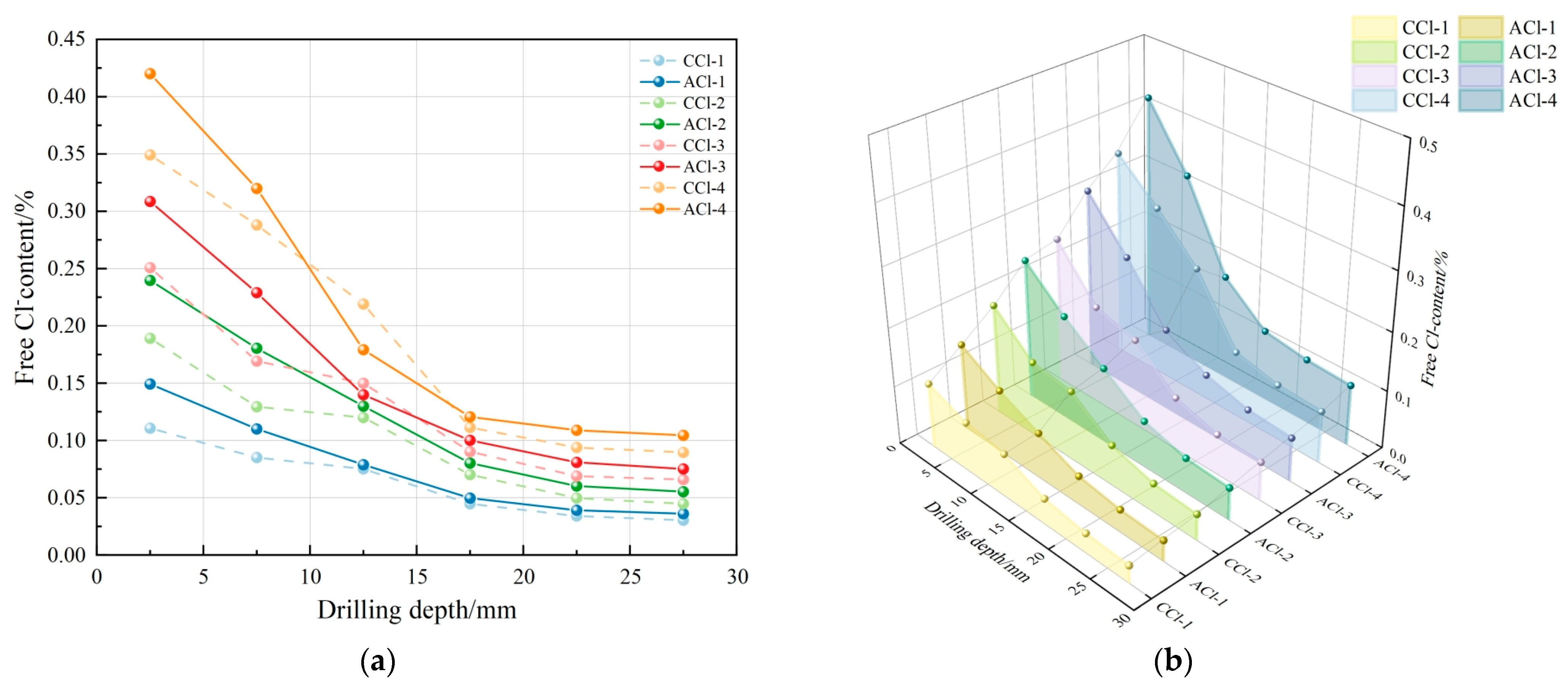
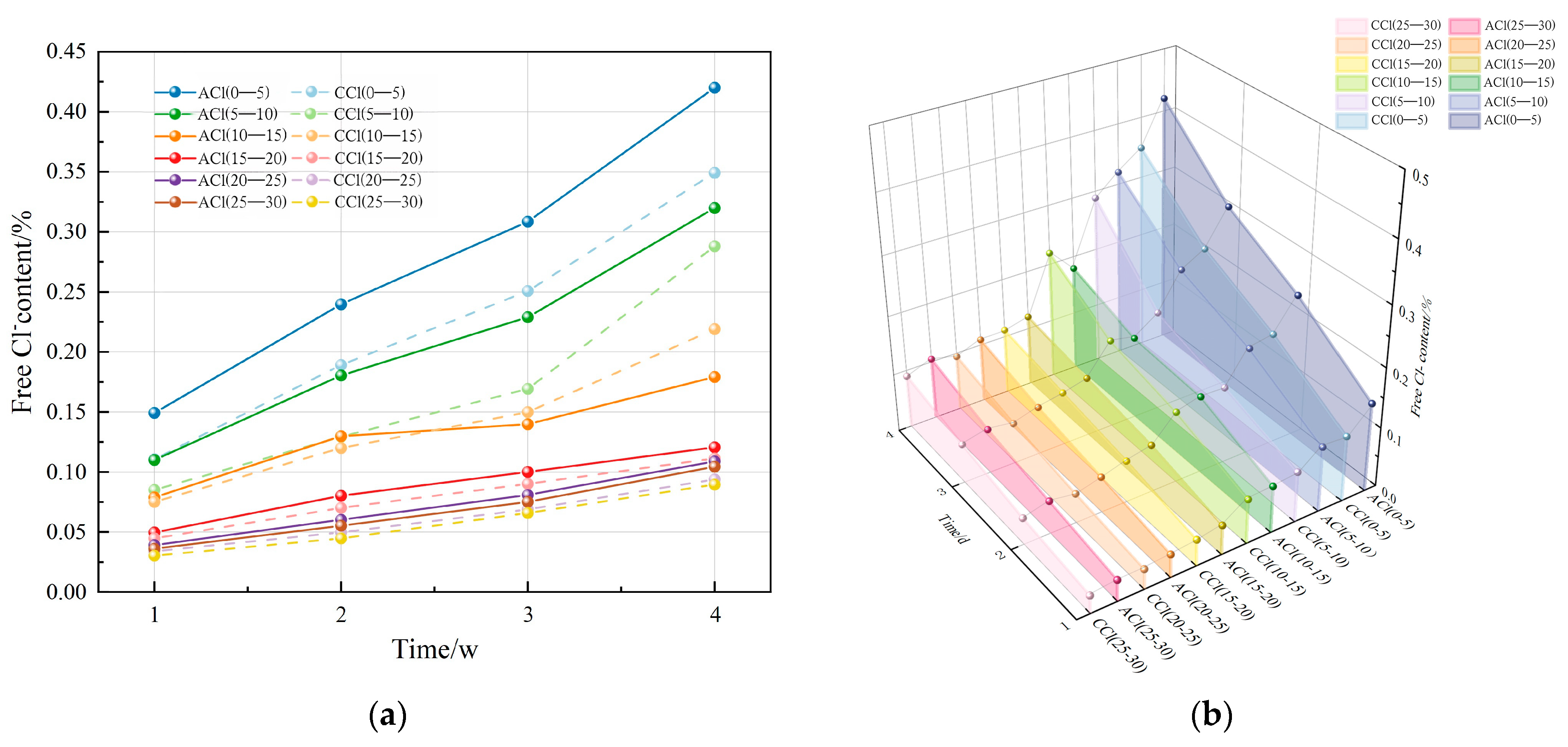
After carbonation, the free chloride content in the concrete exhibited a decreasing trend across all ages, with levels generally diminishing as drilling depth increased. In the fully carbonated zone (0–10 mm drilling depth), the CCl group exhibited a lower free chloride content compared to the ACl group. In the transition zone between carbonated and uncarbonated areas (10–15 mm drilling depth), the CCl group exhibited higher free chloride content compared to the ACl group. In the uncarbonated zone, Cl diffusion was unaffected by carbonation, and the free chloride content between the two groups showed minimal variation.
(4)
Carbonation exerts both positive and negative effects on Cl erosion. The inhibitory effect primarily occurs in the fully carbonated zone, where carbonation products fill the concrete’s internal pores, obstructing Cl diffusion. In contrast, the promoting effect is observed at the interface between the carbonated and uncarbonated zones, where carbonation consumes Ca(OH)2, reducing the formation of Friedel’s salt and thus weakening Cl binding capacity. This causes a rise in free chloride content at the interface, resulting in localized Cl concentration build-up and further promoting Cl diffusion.

Author Contributions

Conceptualization, L.D. and M.Z.; methodology, L.D. and M.Z.; investigation, R.X.; resources, L.D.; data curation, L.D. and M.Z.; writing-original draft preparation, L.D. and M.Z.; writing—review and editing, L.D.; supervision, M.Z.; project administration, R.X.; funding acquisition, R.X. All authors have read and agreed to the published version of the manuscript.

Funding

This research received funding from the “National Natural Science Foundation of China” under grant numbers 52478231 and 52078109.

Institutional Review Board Statement

Not applicable.

Informed Consent Statement

Not applicable.

Data Availability Statement

Data are contained within the article.

Conflicts of Interest

Author Lin Du was employed by the company China Railway Fifth Survey and Design Institute Group Co., Ltd. The remaining authors declare that the research was conducted in the absence of any commercial or financial relationships that could be construed as a potential conflict of interest.

References

  1. Tai, Y.; Yang, L.; Gao, D.; Kang, K.; Cao, Z.; Zhao, P. Properties Evolution and Deterioration Mechanism of Steel Fiber Reinforced Concrete (SFRC) under the Coupling Effect of Carbonation and Chloride Attack. J. Build. Eng. 2024, 95, 110275. [Google Scholar] [CrossRef]
  2. Qu, H.; Feng, M.; Li, M.; Tian, D.; Zhang, Y.; Chen, X.; Li, G. Enhancing the Carbonation and Chloride Resistance of Concrete by Nano-Modified Eco-Friendly Water-Based Organic Coatings. Mater. Today Commun. 2023, 37, 107284. [Google Scholar] [CrossRef]
  3. Ortolan, T.L.P.; Borges, P.M.; Silvestro, L.; da Silva, S.R.; Possan, E.; de Oliveira Andrade, J.J. Durability of Concrete Incorporating Recycled Coarse Aggregates: Carbonation and Service Life Prediction under Chloride-Induced Corrosion. Constr. Build. Mater. 2023, 404, 133267. [Google Scholar] [CrossRef]
  4. Li, T.; Yang, W.; Zhan, M.; Chen, X.; Zhang, L.; Wang, C.; Yang, Y.; Lyv, H. Study on the Microscopic Transmission Characteristics and Coupled Erosion Depth of Tailings Recycled Concrete under the Coupling Effect of Carbonization and Salt-Fog. J. Build. Eng. 2024, 95, 110051. [Google Scholar] [CrossRef]
  5. Li, Y.; Liu, W.; Mi, T.; Ding, X.; Tang, L.; Xing, F. Durability Study of Seawater and Sea-Sand Concrete under the Combined Effects of Carbonation and Chloride Redistribution. J. Build. Eng. 2024, 89, 109294. [Google Scholar] [CrossRef]
  6. Wang, H.; Jiang, M.; Hang, M.; Yang, Y.; Zhou, X.; Liu, X.; Xu, G. Inhibition Resistance and Mechanism of Migrating Corrosion Inhibitor on Reinforced Concrete under Coupled Carbonation and Chloride Attack. J. Build. Eng. 2023, 76, 107398. [Google Scholar] [CrossRef]
  7. Geng, Y.J.; Sun, C.T.; Sun, M.; Zhang, Y.G.; Duan, J.Z. Review of binding mechanisms and influencing factors of chloride ions in cement-based materials. Bull. Chin. Ceram. Soc. 2022, 41, 2604–2617. [Google Scholar]
  8. Ihekwaba, N.M.; Hope, B.B.; Hansson, C.M. Carbonation and electrochemical chloride extraction from concrete. Cem. Concr. Res. 1996, 26, 1095–1107. [Google Scholar] [CrossRef]
  9. Tumidajski, P.J.; Chan, G.W. Effect of sulfate and carbon dioxide on chloride diffusivity. Cem. Concr. Res. 1996, 26, 551–556. [Google Scholar] [CrossRef]
  10. Puatatsananon, W.; Saouma, V. Nonlinear coupling of carbonation and chloride diffusion in concrete. J. Mater. Civ. Eng. 2005, 17, 264–275. [Google Scholar] [CrossRef]
  11. Zheng, Y.L.; Zheng, J.Q.; Zhang, M. Influence of carbonation degree on chloride ion diffusion coefficient in concrete. J. Tongji Univ. (Nat. Sci. Ed.) 2010, 38, 412–416. [Google Scholar]
  12. Chindaprasirt, P.; Rukzon, S.; Sirivivatnanon, V. Effect of carbon dioxide on chloride penetration and chloride ion diffusion coefficient of blended Portland cement mortar. Constr. Build. Mater. 2008, 22, 1701–1707. [Google Scholar] [CrossRef]
  13. Goñi, S.; Guerrero, A. Accelerated carbonation of Friedel’s salt in calcium aluminate cement paste. Cem. Concr. Res. 2003, 33, 21–26. [Google Scholar] [CrossRef]
  14. Hassnan, Z. Binding of External Chloride by Cement Pastes. Master’s Thesis, Department of Building Materials, University of Toronto, Toronto, ON, Canada, 2001. [Google Scholar]
  15. Yuan, C.F.; Niu, D.T.; Qi, G.Z. Experimental study on chloride ion erosion of carbonated concrete under wet-dry cycle mechanism. J. Xi’an Univ. Archit. Technol. Nat. Sci. Ed. 2012, 44, 339–344. [Google Scholar]
  16. Dang, V.Q.; Ogawa, Y.; Bui, P.T.; Kawai, K. Effects of chloride ions on the durability and mechanical properties of sea sand concrete incorporating supplementary cementitious materials under accelerated carbonation conditions. Constr. Build. Mater. 2021, 274, 122016. [Google Scholar] [CrossRef]
  17. Papadakis, V.G.; Vayenas, C.G.; Fardis, M.N. Fundamental modeling and experimental investigation of concrete carbonation. ACI Mater. J. 1991, 88, 363–373. [Google Scholar]
  18. Suryavanshi, A.K.; Narayan Swamy, R. Stability of Friedel’s salt in carbonated concrete structural elements. Cem. Concr. Res. 1996, 26, 729–741. [Google Scholar] [CrossRef]
  19. Oh, B.-H.; Lee, S.-K.; Lee, M.-K.; Jung, S.-H. Influence of carbonation on chloride diffusion in concrete. J. Korea Concr. Inst. 2003, 15, 829–839. [Google Scholar] [CrossRef]
  20. Niu, D.T.; Sun, C.T. Study on the combined effects of concrete carbonation and chloride ion erosion. Bull. Chin. Ceram. Soc. 2013, 41, 1094–1099. [Google Scholar]
  21. Jin, Z.Q.; Sun, W.; Li, Q.Y. Influence of carbonation on chloride ion diffusion in concrete. J. Beijing Univ. Sci. Technol. 2008, 8, 921–925. [Google Scholar]
  22. Sun, C.T. Research on Concrete Durability and Life Prediction Based on Chloride Ion Erosion. Ph.D. Thesis, Xi’an University of Architecture and Technology, Xi’an, China, 2011. [Google Scholar]
  23. Wan, X.M. Research on the Deterioration Mechanism of Concrete Structures Under Combined Mechanical Loads and Environmental Factors. Ph.D. Thesis, Xi’an University of Architecture and Technology, Xi’an, China, 2011. [Google Scholar]
  24. Zhang, P.; Zhao, T.J.; Guo, P.G.; Wittmann, F.H. Effects of freeze-thaw and carbonation on chloride ion erosion of concrete. J. Southeast Univ. Nat. Sci. Ed. 2006, S2, 238–242. [Google Scholar]
  25. Yuan, C.F.; Niu, D.T. Durability research of fly ash concrete in marine atmospheric environment. Bull. Chin. Ceram. Soc. 2012, 31, 1–6. [Google Scholar]
  26. Liu, J.-Z.; Ba, M.-F.; Du, Y.-G.; He, Z.-M.; Chen, J.-B. Effects of chloride ions on the carbonation rate of hardened cement paste by X-ray CT techniques. Constr. Build. Mater. 2016, 122, 619–627. [Google Scholar] [CrossRef]
  27. Liu, J.; Qiu, Q.; Chen, X.; Xing, F.; Han, N.; He, Y.; Ma, Y. Understanding the interacted mechanism between carbonation and chloride aerosol attack in ordinary Portland cement concrete. Cem. Concr. Res. 2017, 95, 217–225. [Google Scholar] [CrossRef]
  28. GB 175-2007; General Portland Cement. Standardization Administration of the People’s Republic of China: Beijing, China, 2007.
  29. GB/T 14685-2011; Standard for Pebble and Crushed Stone. Standardization Administration of the People’s Republic of China: Beijing, China, 2011.
  30. GB/T 14684-2022; Standard for Construction Sand. Standardization Administration of the People’s Republic of China: Beijing, China, 2022.
  31. GB/T 50476-2008; Code for Durability Design of Concrete Structures. Standardization Administration of the People’s Republic of China: Beijing, China, 2008.
  32. SL 352-2018; Specifications for Hydraulic Concrete Testing. Ministry of Water Resources of the People’s Republic of China: Beijing, China, 2018.
  33. GB/T 50476-2009; Standard for Test Methods of Long-Term Performance and Durability of Ordinary Concrete. Standardization Administration of the People’s Republic of China: Beijing, China, 2009.
  34. Li, P.; Li, C.; Li, D.; Chen, R.; Chen, J. Modelling Chloride Diffusion in Concrete with Carbonated Surface Layer. Mag. Concr. Res. 2024, 76, 1048–1058. [Google Scholar] [CrossRef]
  35. Jiang, Z.-L.; Gu, X.-L.; Huang, Q.-H.; Zhang, W.-P. Statistical analysis of concrete carbonation depths considering different coarse aggregate shapes. Constr. Build. Mater. 2019, 229, 116856. [Google Scholar] [CrossRef]
  36. Zhang, Q.Z.; Fang, Y.; Song, L.; Xu, N.; Kang, Z. Relationship between the pore structure of concrete and chloride ion diffusion properties. Bull. Chin. Ceram. Soc. 2022, 41, 2716–2727. [Google Scholar]
  37. Hu, D.G.; Wang, X.H.; Fang, C.Q. Equivalent diffusion coefficient model of chloride ions in cracked concrete structures. Concrete 2022, 393, 24–28. [Google Scholar]
  38. Xu, F.Y.; Liang, Y.Z.; Dai, M.; Lin, L.; Liu, Q.; Dai, L. Research on the effects of chloride ions in seawater on the durability of concrete. Mod. Salt Chem. Ind. 2022, 49, 56–58. [Google Scholar]
  39. Wang, D.Y.; Dong, H.J.; Pang, B.; Chen, J.; Dai, Y. Analysis of the diffusion process of chloride ions in unsaturated flow of concrete beams. MECH-Q 2022, 43, 863–875. [Google Scholar]
  40. Gao, G.Y.; Zhang, C.H.; Ma, F.H. Experimental study on the influencing factors of concrete anti-carbonation performance. Concrete 2020, 368, 30–32. [Google Scholar]
  41. Wang, Y.F. Research on the influence of curing age on the anti-carbonation performance of fly ash concrete. Railw. Constr. Technol. 2022, 8, 10–14. [Google Scholar]
  42. Liu, B.; Chen, D.; Lü, Z.; Rong, H.; Liu, D. Durability Performance of Low-Calcium High-Strength Clinker Cement Concrete under the Combined Action of Chloride Ions and Carbonation. J. Anhui Univ. Technol. (Nat. Sci. Ed.) 2024, 1–7. Available online: http://kns.cnki.net/kcms/detail/34.1254.N.20240726.1505.004.html (accessed on 17 November 2024).
  43. Li, Y. Study on the Deterioration Mechanism of Chloride Salt-Containing Reinforced Concrete Under the Coupled Action of Carbonation and Chloride Ions. Ph.D. Thesis, Institute of Engineering Mechanics, China Earthquake Administration, Harbin, China, 2023. [Google Scholar] [CrossRef]
  44. Mei, K.; He, Z.; Yi, B.; Lin, X.; Wang, J.; Wang, H.; Liu, J. Study on Electrochemical Characteristics of Reinforced Concrete Corrosion under the Action of Carbonation and Chloride. Case Stud. Constr. Mater. 2022, 17, e01351. [Google Scholar] [CrossRef]
  45. Al-Ameeri, A.S.; Rafiq, M.I.; Tsioulou, O. Combined Impact of Carbonation and Crack Width on the Chloride Penetration and Corrosion Resistance of Concrete Structures. Cem. Concr. Compos. 2021, 115, 103819. [Google Scholar] [CrossRef]
  46. Sun, M.; Bao, Q.; Ding, G.J.; Zhang, P.; Sun, C. Influence of fly ash on the carbonation and chloride ion erosion characteristics of concrete. Highway 2021, 66, 295–299. [Google Scholar]
Figure 1. Powder drilling, bagging, and drying process: (a) drilling powder; (b) grouping and bagging of powder; (c) placing in oven.
Jmse 13 00097 g001
Figure 2. Titration process for determining free Clcontent: (a) extract the filtrate; (b) add phenolphthalein reagent; (c) neutralize with dilute sulfuric acid; (d) add potassium chromate indicator; (e) titrate with AgNO3.
Jmse 13 00097 g002
Figure 3. Method for assessing concrete carbonation depth: (a) cutting the specimen; (b) spraying; (c) measuring carbonation depth.
Jmse 13 00097 g003
Figure 4. Carbonation depth of concrete at different ages.
Jmse 13 00097 g004
Figure 5. Relationship between carbonation depth and NaCl solution concentration.
Jmse 13 00097 g005
Figure 6. Microstructure of the W + C group concrete after 28 days of carbonation: (a) 5000× magnification; (b) 10,000× magnification.
Jmse 13 00097 g006
Figure 7. Microstructure of the Cl-15 + C group concrete after 28 days of carbonation: (a) 5000× magnification; (b) 10,000× magnification.
Jmse 13 00097 g007
Figure 8. Relationship between free Cl content and drilling depth in concrete: (a) 2D plot; (b) 3D plot.
Jmse 13 00097 g008
Figure 9. Relationship between free Cl content and number of cycles in concrete: (a) 2D plot; (b) 3D plot.
Jmse 13 00097 g009
Figure 10. Microstructural morphology of the ACl group concrete: (a) 5000× magnification; (b) 10,000× magnification.
Jmse 13 00097 g010
Figure 11. Microstructural morphology of the CCl group concrete: (a) 5000× magnification; (b) 10,000× magnification.
Jmse 13 00097 g011
Table 1. Main performance indicators of the cement.
Performance
Indicator
Standard
Consistency
Initial Setting TimeFinal
Setting Time
Stabilizing
Properties
Compressive
Strength (MPa)
Water
Demand (%)
(min)(min)3 d28 d
Standard
Requirement
≤28≥45≤600Must pass≥3.5Standard
Requirement
Test Results25.8139346Passed11.1Test Results
Table 2. Cement’s chemical composition.
Chemical
Component
SiO2CaOAl2O3Fe2O3SO3MgOLoss on Ignition
Standard
Requirement
----≤3.5≤5.0≤3.0
Actual Content21.0861.965.123.682.461.851.57
Table 3. Main performance indicators of basalt crushed stone.
Technical
Indicator
Apparent Density (kg/m3)Bulk Density (kg/m3)Mud Content (%)Moisture Content (%)Crushing Value (%)Needle-Flake Content (%)
Measured Value270516020.3808.123.1
Table 4. Main performance indicators of the water-reducing agent.
Performance
Indicators
Water
Reduction Rate at 20 °C
Plastic
Consistency
Drying ShrinkageWater-Binder RatioApplicable Temperature RangeAir
Content
Effect on Setting Time
Units%mmmm/m——°C%min
Reference Values≥15%180–220≤0.05≤0.4−5 to 40≤5≤30
Table 5. Mix proportion of marine concrete (kg/m3).
MaterialDesignationWaterCementSandAggregateSuperplasticizer
Ordinary
Concrete
PC205465.95761175.81.86
Table 6. Immersion duration, carbonation periods, and number of specimens.
DesignationImmersion DurationCarbonation PeriodsNumber of Specimens
W + CWater (28 days)3, 7, 14, 28 days3
Cl-5 + C5% NaCl (28 days)3, 7, 14, 28 days3
Cl-10 + C10% NaCl (28 days)3, 7, 14, 28 days3
Cl-15 + C15% NaCl (28 days)3, 7, 14, 28 days3
Table 7. Specimen exposure conditions and curing durations.
Sample IDExposure ConditionsImmersion AgeNumber of Specimens
CClCarbonation (28 days)1, 2, 3, 4 weeks8
AClAir under same conditions (28 days)3, 7, 14, 28 days3
Table 8. Cl diffusion coefficients in concrete (10−5 mm2·s−1).
Number1 Week2 Weeks3 Weeks4 Weeks
ACl27.63105.0254.847
CCl13.857.5563.4622.356
Disclaimer/Publisher’s Note: The statements, opinions and data contained in all publications are solely those of the individual author(s) and contributor(s) and not of MDPI and/or the editor(s). MDPI and/or the editor(s) disclaim responsibility for any injury to people or property resulting from any ideas, methods, instructions or products referred to in the content.

