1. Introduction
With the rapid growth of global ocean development, the continuous increases in the types, numbers, and sizes of ships has resulted in severe marine pollution. Consequently, international organizations such as the International Maritime Organization have implemented low-carbon strategies and greenhouse gas (GHG) reduction initiatives [
1,
2,
3,
4]. Shipboard power grids face several challenges, including a limited capacity, complex operating conditions, significant load fluctuations, and instability caused by shore power connections [
5,
6,
7,
8,
9]. Due to the greenhouse gas emissions and environmental pollution associated with traditional fossil-fueled ships, the development of hydrogen fuel cell systems has garnered significant attention. However, fuel cells exhibit slow dynamic responses to load fluctuations, making it difficult to adapt to the complex operating conditions of ships. As a result, hybrid energy storage systems (HESSs) incorporating batteries and supercapacitors are required to stabilize the power grid and enhance grid stability [
10,
11,
12]. An efficient EMS is critical for coordinating power flows, reducing operational costs, preventing stability issues, and ensuring safe operation [
13,
14,
15,
16].
Currently, EMS research can be categorized into three main types: rule-based control (RBC) strategies, optimization-based control strategies, and artificial intelligence-based strategies. For rule-based control strategies, the rules rely on expert experience or mathematical calculations and include methods such as rule-based control [
17,
18], fuzzy logic control [
19], low-pass filter-based control [
20,
21], and wavelet transform-based control [
22], among others. These strategies are computationally efficient, intuitive, easy to implement, robust, and effective in deterministic scenarios. However, they lack self-learning and adaptive capabilities, making them unsuitable for complex operating conditions.
The second category comprises optimization-based strategies, which are more complex but also more effective. They use objective functions to evaluate hybrid power system performance, such as minimizing costs or maximizing lifespan. Examples include dynamic programming [
23], model predictive control (MPC) [
24], and particle swarm optimization (PSO) [
25]. DP is an algorithm used to find the global optimal solution to a problem. Given known operating conditions, it can solve for the optimal result of the objective function. For instance, W. Tang et al. [
26] propose a hierarchical EMS based on adaptive dynamic programming (ADP); the proposed EMS ensures real-time planning speed and good following performance while reducing energy consumption. Similarly, N. Xu et al. [
27] propose a global optimization framework of “information layer–physical layer–energy layer–dynamic programming” (IPE-DP), which can realize the unity of different information scenarios, different vehicle configurations, and energy conversions. Although DP can achieve offline optimization, its computation time is relatively long, and when the discretized grid is too fine, it can lead to the “curse of dimensionality” [
28]. Therefore, it is necessary to apply the offline optimal strategy in real time by combining other methods.
The third category is artificial intelligence (AI)-based strategies, which leverage advances in AI technology for energy management control. These include methods like neural networks [
29], reinforcement learning [
30], and support vector machines [
31]. AI algorithms have been widely applied to vehicle energy management and are increasingly used in hybrid power systems [
32,
33]. For example, C. Qi et al. [
34] propose a multi-agent reinforcement learning algorithm that incorporates vehicle operation features, enabling generalization across different vehicle models. Reference [
35] developed a deep reinforcement learning-based framework for plug-in hybrid electric vehicles (PHEVs), combining offline training with online control. By addressing continuous state and action spaces through Lagrange relaxation, the system effectively learned from real driving data, resolving safety and overestimation issues while achieving an optimal energy management system.
To effectively adapt to highly dynamic conditions and ensure fuel-efficient operations while meeting instantaneous load demands, many researchers have combined multiple approaches. WU et al. [
36] propose a predictive EMS using multiple neural networks, where DP results trained a pattern recognition network, and a recurrent neural network was applied for online dynamic estimation. Yang, N. et al. [
37] propose a real-time EMS for hybrid electric vehicles by integrating reinforcement learning into an MPC framework, addressing RL’s drawbacks of a long learning time and poor adaptability, and significantly improving MPC’s real-time performance. Waqar Waheed and Qingshan Xu [
38] demonstrate and incorporate a deep learning neural network model with time series analysis and feature selection to forecast the complex and variable hourly load demand and involve a comprehensive comparison between the DNN approach and other alternatives for short-term load forecasting.
After reviewing the current efforts on the development of onboard energy management systems, it becomes evident that it is inevitable to make trade-offs among multiple factors. Considering the unique characteristics of the onboard loads, long-term regularity and short-term unpredictability, both aspects play pivotal roles in optimizing power-sharing decisions. The dynamic nature of real-time power demands has remained a challenge.
To solve the above problems, a two-layer EMS based on prior knowledge of the ship is proposed. This strategy demonstrates strong adaptability to ship loads and low computational costs, enabling optimal power distribution in real time. The main contributions of this paper are as follows:
Proposing a two-layer EMS integrating historical operating conditions—this EMS comprises an offline optimization layer and a real-time energy management layer.
Leveraging historical operating characteristics—using neural networks to extract optimal allocation results, the strategy provides near-optimal management strategies in real time with low computational costs.
Eliminating the need for a manual analysis of offline optimal strategies—the proposed EMS only requires typical ship operating conditions as input for training, eliminating the need for a manual analysis of the offline optimal strategy characteristics. This allows the system to derive corresponding control strategies for different cruising missions and complex conditions, making it easily applicable to the energy management systems of other ships.
The remainder of the paper is organized as follows:
Section 2 presents the configuration of the ship’s integrated power system and provides a model for the hybrid energy storage system (HESS).
Section 3 elaborate on the offline optimization strategy of the first layer and the real-time energy management method of the second layer, respectively.
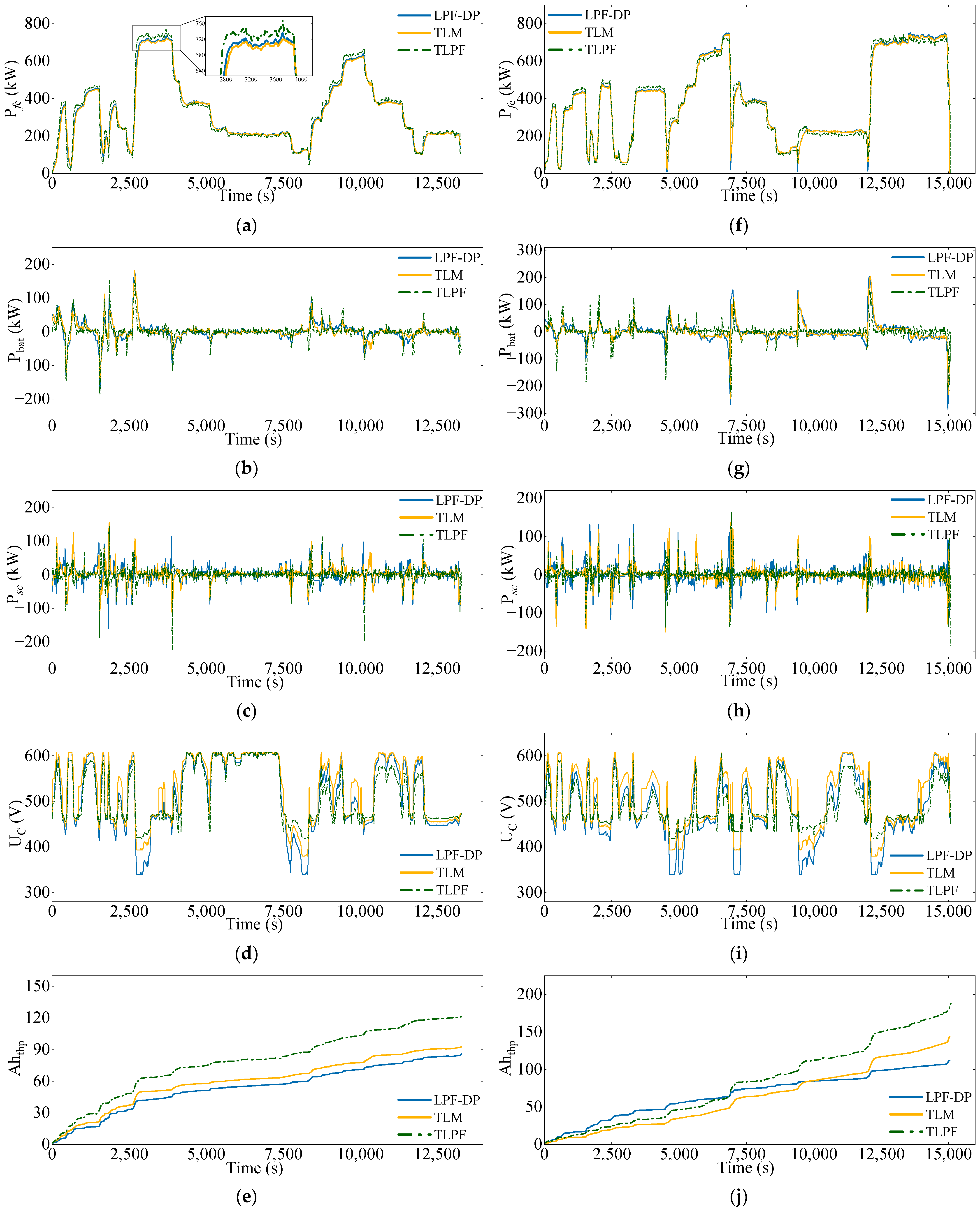
Section 4 validates the proposed strategy by generating random load conditions and compares the performance of TLPF, LPF-DP, and the proposed two-layer energy management model (TLM). Finally,
Section 5 provides the conclusions.
3. Methods
3.1. Typical Operating Conditions of the Ship
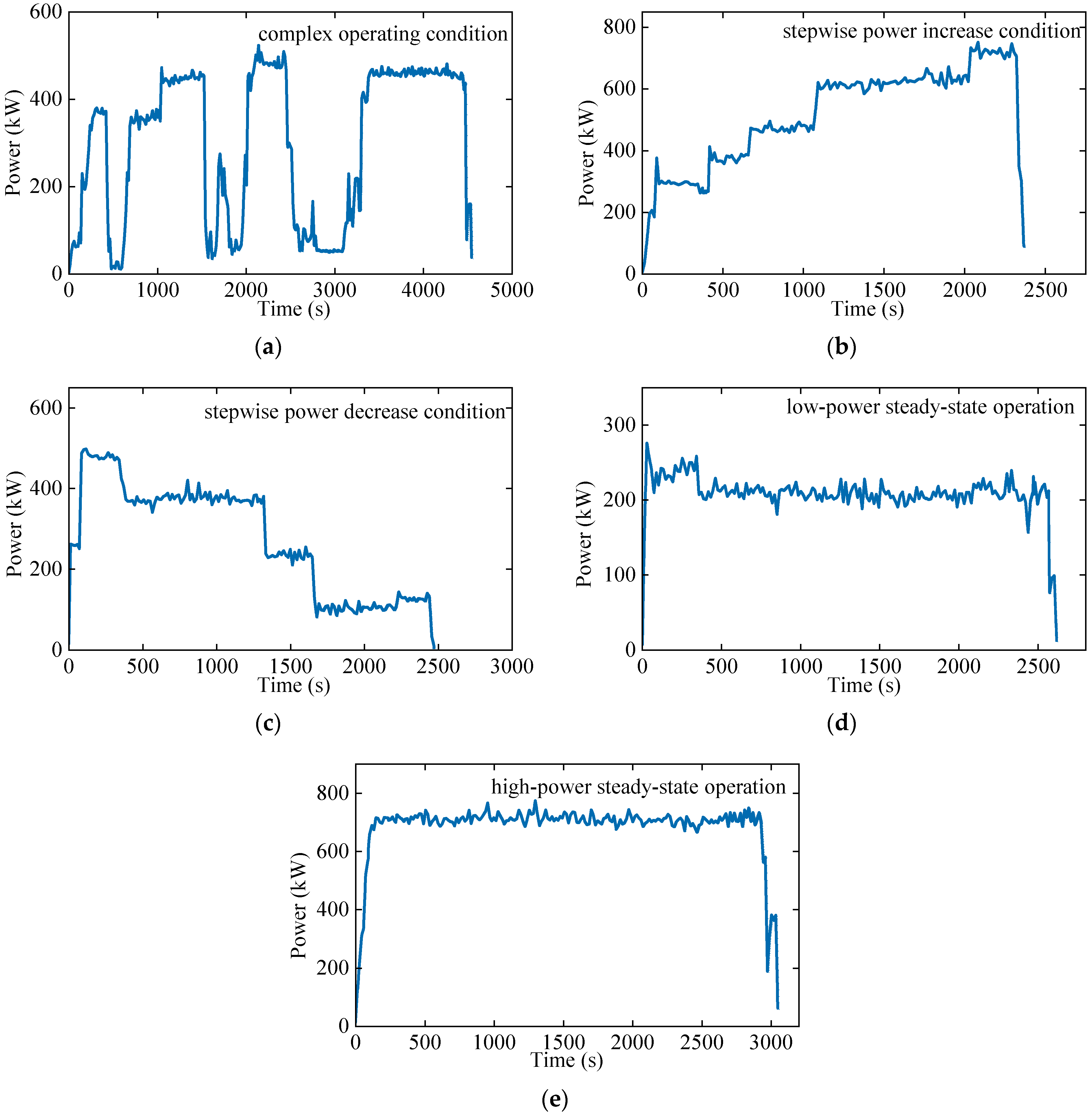
During different operational phases and mission scenarios, a ship’s load exhibits diverse characteristics. Accurately extracting the typical operating conditions of a ship is crucial for performance evaluation, operational optimization, and equipment maintenance. By analyzing historical load data from the ship’s operations, the typical operating conditions can be effectively summarized. Before extracting these typical conditions, performing essential preprocessing of the raw data is necessary to remove anomalies and missing values caused by sensor failures, communication interference, or other factors, ensuring data quality and usability.
Key features such as the mean, variance, and variance-to-mean ratio of power fluctuations are selected to characterize the ship’s operating conditions. The mean represents the average power level, the variance measures the dispersion relative to the mean, and the variance-to-mean ratio reflects the temporal variation of power, calculated as the difference between each second’s power value and that of the previous second.
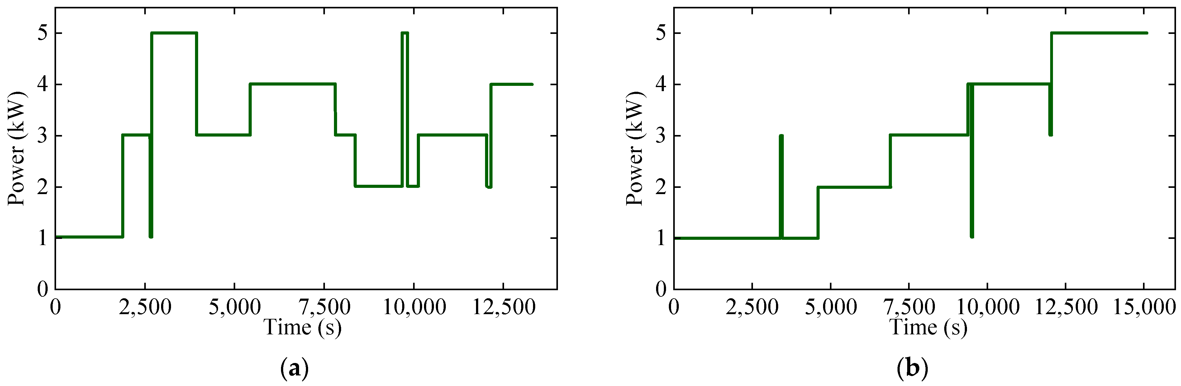
The K-Means clustering algorithm, a commonly used partition-based clustering method, is employed due to its simplicity, efficiency, and ease of implementation. Using K-Means clustering, the ship’s operating load data are classified, extracting five typical operating conditions.
Figure 2a–e illustrates these conditions: complex operating condition, stepwise power increase condition, stepwise power decrease condition, high-power steady-state operation, and low-power steady-state operation.
The vessel studied in this paper is the “Three Gorges Hydrogen Vessel No. 1” in Chi-na. The load data shown in
Figure 2, along with the corresponding ship configuration, are sourced from this vessel.
3.2. Offline Energy Management Strategy
3.2.1. Optimization Problem
The objective of the energy management system optimization in this study is to minimize the average fluctuations of the fuel cell and the degradation of the lithium-ion battery pack. Additionally, a penalty function is introduced to limit the ripple of the lithium battery pack, thereby improving the power supply quality of the grid. Severe fluctuations in load power transmitted to the fuel cell stack can directly cause output voltage instability, accelerate fuel cell degradation, and reduce the efficiency of the fuel cell stack. Power fluctuations in the fuel cell stack are often accompanied by uneven changes in heat generation rates, leading to thermal management issues. Therefore, the power fluctuation of the fuel cell stack is set as one of the objective functions. The expression for the average fuel cell fluctuation can be described as follows [
40]:
where
is the output power of the fuel cell stack at time
t, and T is the running time.
The degradation of lithium battery life is reflected in its actual usable capacity being less than the initial capacity. When the actual capacity drops to 80% of the initial capacity, the battery is considered to have reached the end of its life. Improper cycling conditions, such as frequent charging and discharging or high-current charging and discharging, can accelerate battery degradation and even lead to failure. Therefore, the design of energy management strategies must consider the cost of lithium battery life degradation. The cost model for lithium battery life degradation can be expressed as follows [
41]:
In the above equation, represents the average cost of batteries (USD/kWh), the factor of 2 in the denominator represents one complete charge–discharge cycle, and is the energy released by the battery. is the average cycle number of the lithium battery as a function of the depth of discharge, represents the depth of discharge (DOD), and and are the charging and discharging efficiencies of the lithium battery, respectively. is the discharge power, and is the discharge time. The charge and discharge efficiency is set at 98% and is 500 (USD/kW·h).
The relationship between the typical average cycle number of a lithium battery and its depth of discharge can be modeled as follows [
41]:
In the above equation, a and b are the parameters obtained from fitting the life cycle curve.
When the battery operates within the rated current range, the cycle number is primarily related to the DOD. Here, the DOD is defined as the proportion of energy released during a single discharge event relative to the total capacity of the battery, expressed as follows [
42]:
Substituting Equations (7) and (8) into Equation (6) and simplifying yields the following:
To ensure that the fuel cell stack and the EMS operate under normal conditions, the corresponding constraints need to be applied:
3.2.2. DP-LPF-Based Power Splitting Strategy
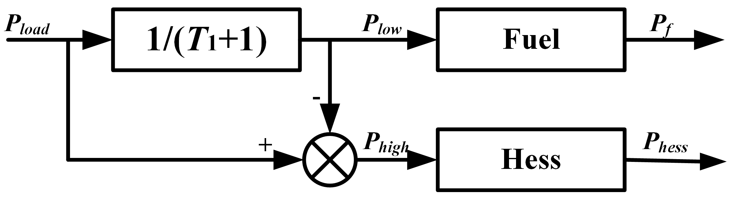
When a ship operates under different conditions, its load exhibits varying fluctuation characteristics. Under stable conditions, the load typically consists of low-frequency fluctuations with smaller variations, while under complex conditions, the power changes rapidly and exhibits larger high-frequency fluctuations. Therefore, a power allocation method based on the nature of power fluctuations is more consistent with the characteristics of shiploads. Among these methods, the low-pass filtering-based power allocation method is the most studied and widely used. This approach divides the load into high-frequency and low-frequency components through a low-pass filter, where the high-frequency power is handled by the Hybrid Energy Storage System (HESS), and the low-frequency power is managed by the fuel cell. This reduces power fluctuations in the fuel cell stack. The control strategy is illustrated in
Figure 3.
Dynamic programming can determine the optimal control input by designing an optimization objective function. For the battery/supercapacitor HESS, the optimization objective in this work is to minimize battery capacity degradation while limiting the power ripple of the lithium battery. The load power of the hydrogen-powered ship is discretized with a 1-s step size, and the state variables and control variables are discretized into discrete arrays. The DP algorithm is then used to solve the objective function over the time steps. The state variables in this paper are , and the control variables are . The initial values are set to and . Based on the typical operating load of the ship, the DP algorithm adopts a backward optimization approach. After discretization, the algorithm starts from the last step’s state variables and searches for the optimal solution at each step through the control variables, thereby determining the optimal decision for each step. A forward solution is then performed to obtain the overall optimal strategy for the optimization process. The goal is to minimize lithium battery capacity degradation while incorporating a penalty function to limit the power ripple of the lithium battery.
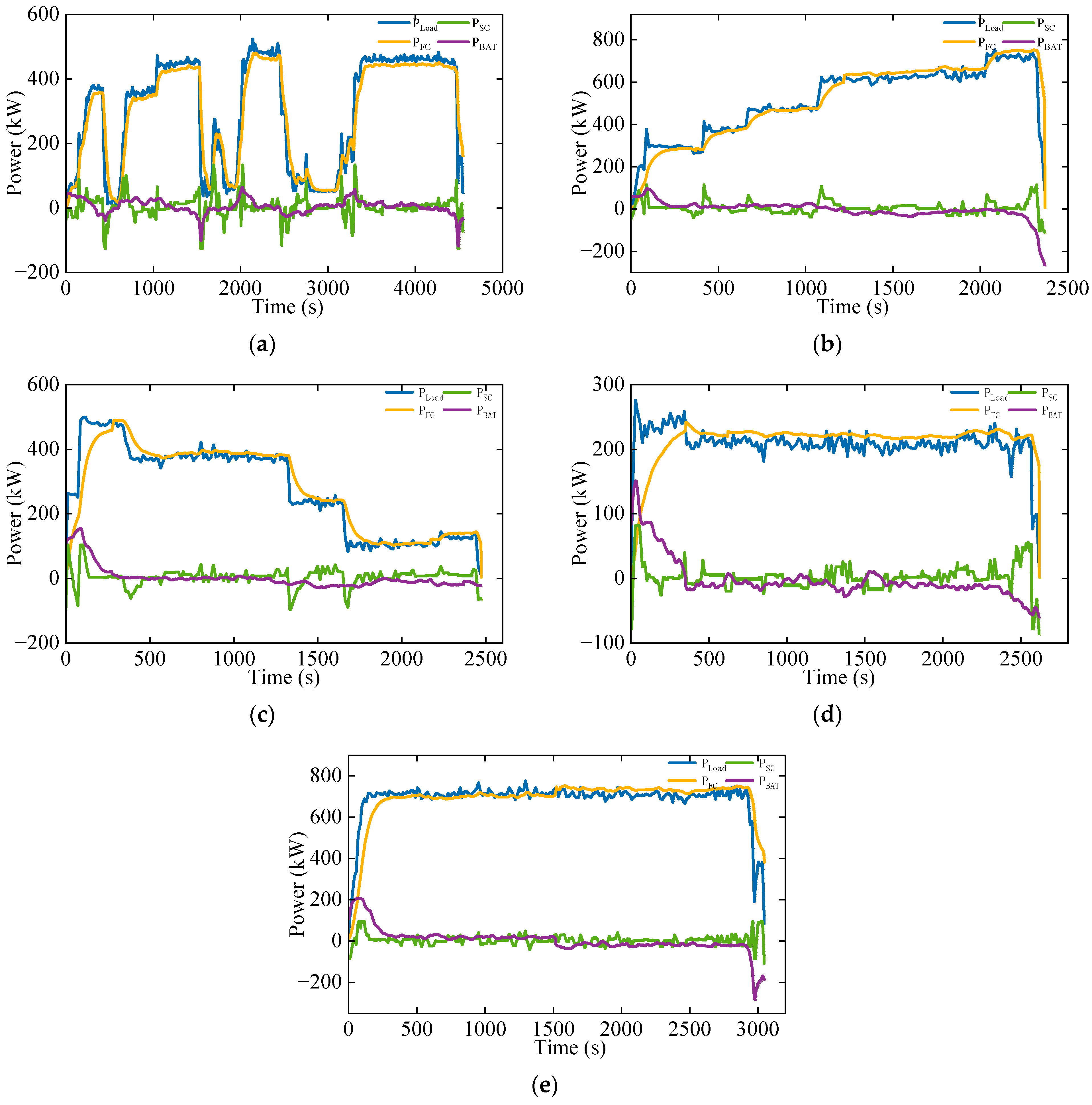
Based on the above strategy, the optimal power allocation modes are provided for five typical operating conditions of the ship. The detailed allocation results are shown in
Figure 4. These results provide effective guidance strategies for the operation of the power system.
The fuel cell handles the main power variations and strives to reduce power fluctuations to minimize grid instability, thereby improving the power supply quality and safety.
The supercapacitor manages the high-frequency components of the remaining power filtered by the low-pass filter, handling short-term high-frequency power fluctuations.
The lithium battery provides power to compensate for higher low-frequency power demands while ensuring that the SOC of the lithium-ion battery returns to its initial level as much as possible before and after use.
3.3. Proposed Real-Time Two-Layer Energy Management Strategy
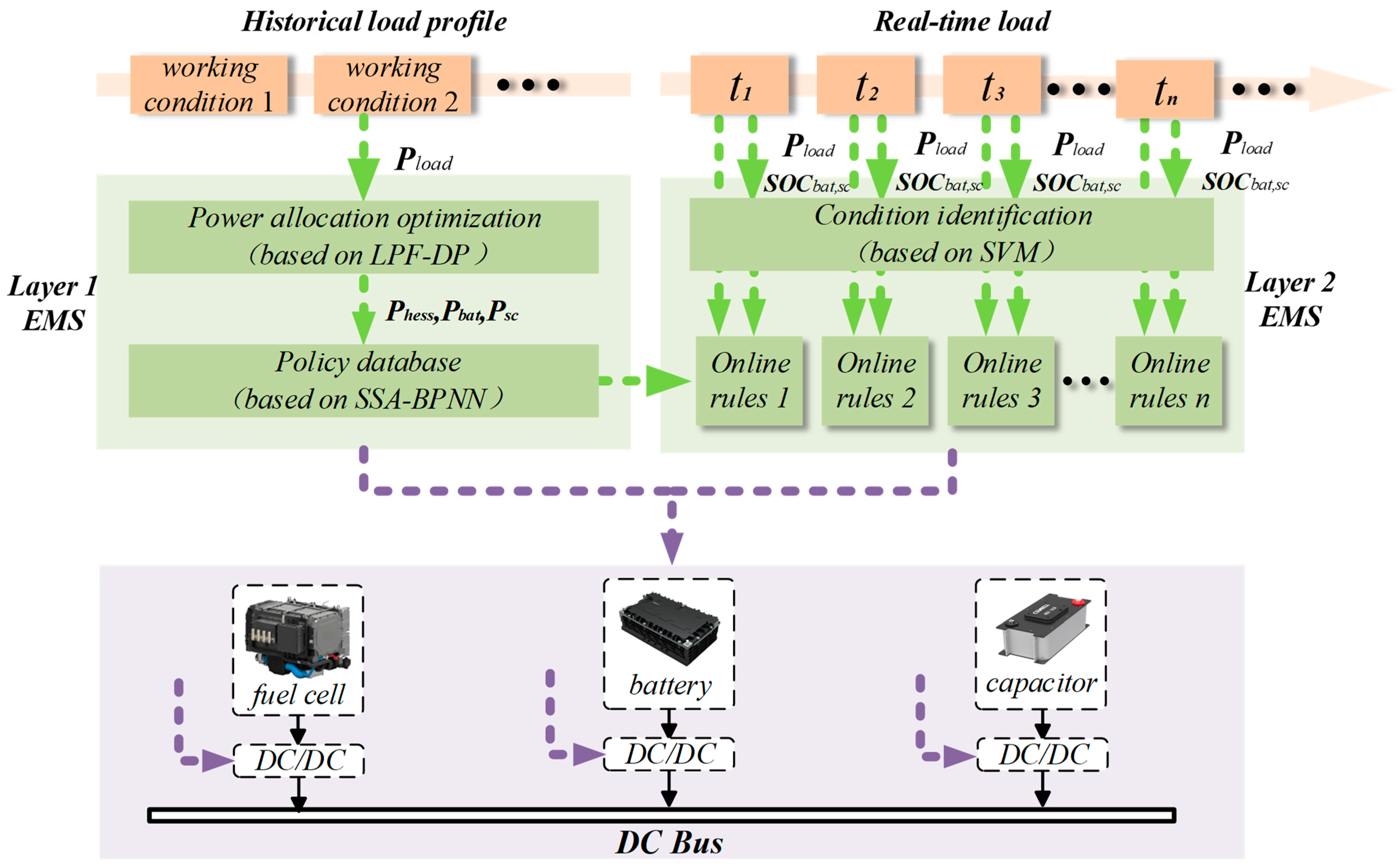
In this paper, a two-layer energy management system based on prior knowledge is proposed to reduce power fluctuations in the fuel cell stack, enhance the stability and safety of the ship’s power grid, reduce the probability of power outages, and consider the service life of the lithium-ion battery pack. The overall structure of the proposed EMS is shown in
Figure 5. This figure serves as the core representation of the research methodology employed in this study, encapsulating the key elements and their interrelationships within the EMS framework.
The EMS of this study focuses on a hybrid power system integrating fuel cells with a hybrid energy storage system, including lithium batteries and supercapacitors. The fuel cell stack serves as the primary power source, supplying the majority of the energy to the ship’s power grid. Meanwhile, lithium-ion batteries and supercapacitors function as auxiliary power sources to stabilize power grid performance, reduce the load on the primary power source, and enhance energy recovery and utilization. The proposed method is designed for application in small- to medium-sized ships equipped with electric propulsion systems.
The first layer leverages prior knowledge of the ship’s operating conditions. It begins with the offline computation of the power distribution results for the fuel cell stack and the hybrid energy storage system under typical operating scenarios. An improved BP neural network is employed to learn the optimal power distribution strategies corresponding to various typical conditions, thereby constructing an offline-trained strategy repository.
The second layer employs a support vector machine model trained using the characteristic parameters of typical ship operating conditions. Real-time load data are processed through the SVM model to identify the current operating condition of the ship. Based on the identified operating condition, the corresponding optimal power distribution strategy is retrieved from the offline strategy repository. Additionally, the SOC of the lithium battery and supercapacitor is updated in real time to ensure the reliable operation of the energy storage system.
3.3.1. First-Layer Energy Management System
Since the DP algorithm requires prior knowledge of the entire driving condition’s speed profile and its solving process suffers from the curse of dimensionality, which requires significant computation time, it is challenging to apply this method to real-time ship controllers. Therefore, extracting the optimal energy management strategy from the offline power allocation results is necessary.
The backpropagation neural network, also known as the error backpropagation neural network, is a multilayer feedforward neural network trained using the error backpropagation algorithm. It is one of the most widely used neural network models and possesses powerful nonlinear mapping capabilities, adaptability, and generalization abilities. It can be applied to various fields, such as function approximation, pattern recognition, classification, and data compression. Therefore, the BPNN can be trained in advance using offline power allocation results, allowing it to provide timely power distribution outcomes during real-time control based on the current ship operating conditions.
The working principle of the BPNN involves inputting data into the network through the input layer, processing it sequentially in the hidden layer based on the connection weights between neurons, and finally reaching the output layer to obtain the output result. Assume the network has n inputs, m outputs, and s neurons in the hidden layer. The output of the hidden layer is
, the threshold of the hidden layer is
, and the threshold of the output layer is
. The transfer function of the hidden layer is
, and that of the output layer is
. The weight between the input layer and the hidden layer is
, and the weight between the hidden layer and the output layer is
. The output of the grid
is then obtained, and the desired output is
. The output of the jth neuron in the hidden layer can be expressed as follows [
43]:
The output layer can be expressed as follows:
The error function can be expressed as follows:
The BP neural network reduces network errors by continuously adjusting the weights. Weight training generally uses the gradient descent method, which is prone to falling into local optima and unable to achieve global optimization. The Sparrow Search Algorithm (SSA) has strong global search capabilities and does not rely on gradient information. It simulates the foraging and anti-predation behaviors of sparrow populations to explore the entire solution space.
By introducing SSA, the globally minimal weights for BP neural network errors can be obtained, improving the overall network performance. The SSA is set with an initial population of 30, a maximum number of 50 evolution iterations, a safety value of 0.6, and a discoverer ratio of 0.7.
To apply the optimization results of DP, the SSA-BP neural network is used to learn the optimal power allocation data obtained from DP. The optimization data of five typical operating conditions are used as samples to train corresponding neural network models, resulting in control strategies suitable for the five typical conditions. The initial, and , and of the ship’s typical operating conditions are taken as inputs for the neural network, while the outputs are the supercapacitor power and lithium battery power. The number of hidden neurons is determined through iterative optimization.
To verify the effectiveness of the SSA-BP neural network proposed in this paper, the BP neural network and NFN [
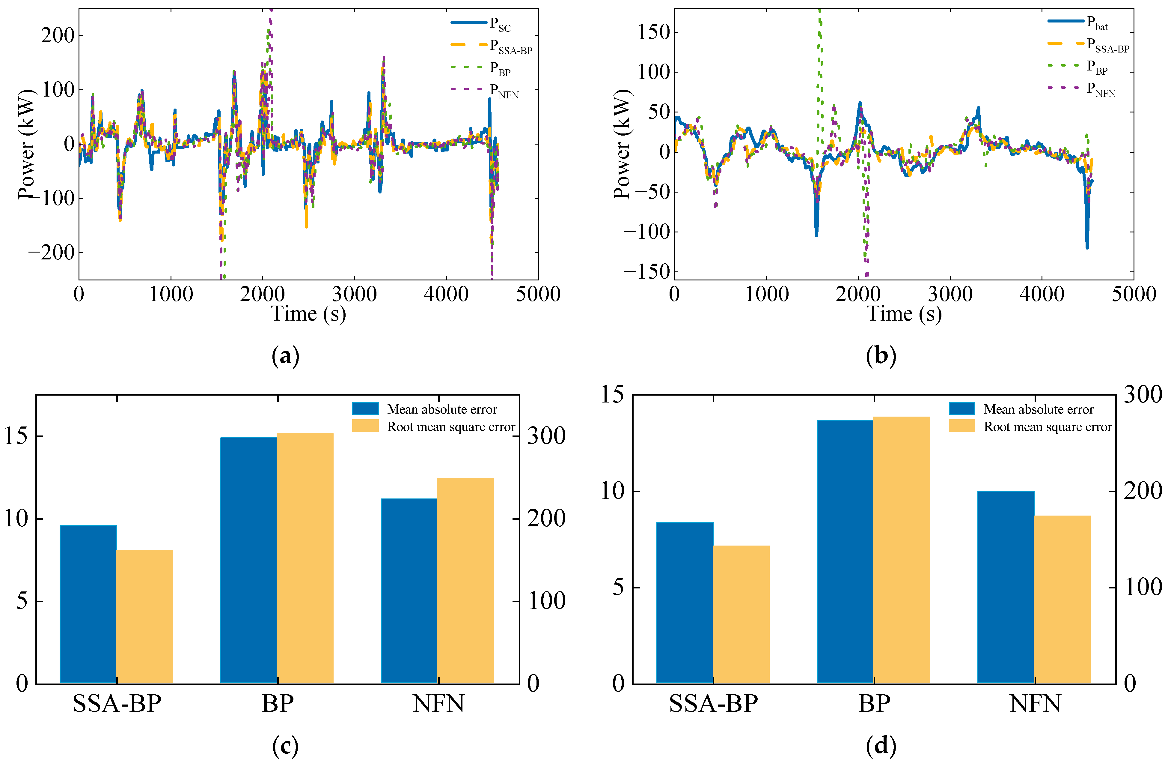
29] were used to learn the optimal power allocation data obtained from DP, and the power allocation results output by different neural networks were compared.
Figure 6 shows the offline optimization results and three different neural network outputs under complex ship operating conditions. From
Figure 6a, b, it can be concluded that compared to other neural networks, the proposed SSA-BP neural network has the highest similarity with the results obtained from offline computation.
Figure 6c, d indicates that the average absolute error and root mean square error between the output results of SSA-BP and offline results are the smallest.
Table 3 compares the two algorithms. The computation time for SSA-BP is only 49.8 s, while that for LPF-DP is 21,092 s, indicating that SSA-BP has a response time of just 10.9 ms, which meets the requirements for real-time power allocation on ships. It significantly improves computation speed, with the fuel cell fluctuation rate
increasing by only 11% and the lithium battery degradation cost
increasing by just 9.9%.
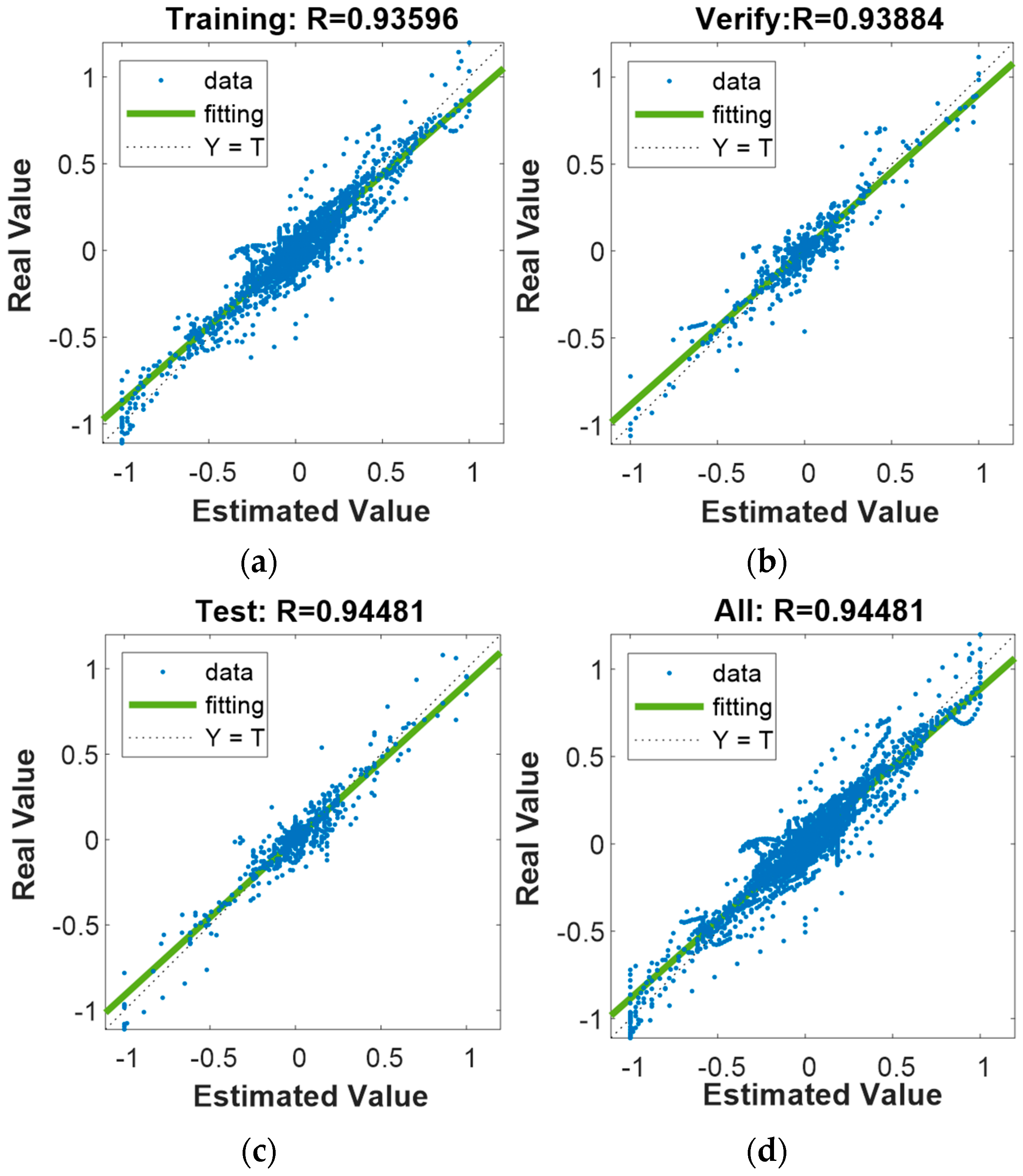
The regression relationship between the actual power and estimated power is shown in
Figure 7. The R values of different datasets are all above 0.93, indicating a fitting accuracy of over 93%. This demonstrates that the neural network optimized by SSA has a high degree of fitting to the offline power allocation results, allowing it to derive near-optimal strategies during real-time power allocation that closely match the offline calculations.
3.3.2. Second-Layer Energy Management System
The second-layer energy management system is built upon the offline strategy repository established in the first layer. First, the characteristic parameters of typical operating conditions are input into the SVM model for training. During the real-time operation of the ship, the real-time load is processed through the SVM model to identify the current operating condition of the ship. Based on the identified condition, the optimal power distribution strategy is retrieved from the offline strategy repository created in the first layer. Furthermore, the SOC of the lithium battery and supercapacitor is updated in real time to ensure the stable and efficient operation of the energy storage system.
The SVM model is a widely used algorithm in the field of machine learning due to its simplicity and broad applicability. Based on the fundamental strategy of supervised learning, it enables the learning machine to pursue structural risk minimization, thereby improving the generalization ability while achieving a minimal confidence range and empirical risk. With its excellent performance in handling classification and regression problems, SVM has shown significant potential in the field of ship operating condition identification.
Its core idea is to find an optimal hyperplane in the feature space that separates samples from different classes as accurately as possible while maximizing the margin between the two classes and the hyperplane. For a given sample
, the hyperplane is defined as follows [
44]:
where
is the coefficient and
is the intercept. Using the above formula, the distance from each point to the classification hyperplane can be calculated. Suppose there is a point
in the dataset, where
is the
i variable, and n is the dimension. The distance calculation formula is as follows:
where
and
is the norm of the hyperplane. All support vectors are searched, and the distances are calculated. The hyperplanes corresponding to all eligible distances are compared, and the hyperplane corresponding to the maximum distance, i.e., when
is maximized, is retained for
and
.
For linearly inseparable datasets, support vector machines introduce a kernel function to map the data from the original feature space to a higher-dimensional feature space, making the data linearly separable in this new space. Commonly used kernel functions include the linear kernel, polynomial kernel, and Gaussian Radial Basis Function (RBF) kernel.
Based on the characteristics of the ship’s operating condition identification problem, an extended method of multi-class SVM is adopted. The load data from five typical operating conditions of the ship are input into the SVM for training, with an 8:2 split between the training set and the test set.
During actual ship operation, the load exhibits extremely complex variation patterns. On one hand, the load on the power system varies significantly across different operational phases, such as starting, accelerating, cruising at a constant speed, decelerating, and docking. Moreover, external factors such as environmental changes frequently impact the load, making the variations even more intricate. On the other hand, sensor interference cannot be ignored. The various sensors installed on the ship may experience signal transmission instability and data collection deviations due to prolonged operation and the challenging marine environment.
Given the aforementioned complexities, traditional static data processing methods struggle to effectively handle these diverse and variable interfering factors, allowing data noise to infiltrate and affect the accuracy of operating condition identification. Using a rolling time window for condition identification is an effective strategy. The rolling time window dynamically segments and analyzes the ship’s operational data based on a predefined time range. By continuously updating the data within the time window, it can better adapt to load variations and filter out data noise caused by various interfering factors, thereby improving the precision and reliability of condition identification.
The ship condition recognition in this study adopts a rolling time window, where the time window , is the discretized time step (set to 1 s in this study). This means that the condition identification at the current moment is based on the common features of data from the current moment and the preceding 19 s to determine the ship’s current operating condition category. The SVM-based strategy achieves an accuracy of 90.2%. This indicates that SVM can accurately identify the ship’s current operating condition during operation.
5. Conclusions and Discussion
In response to the complex operating conditions of ships and by leveraging historical operational data, this paper proposes a two-layer energy management system for hydrogen-powered hybrid ship systems. The first layer of the EMS is based on offline optimization, utilizing DP and LPF to determine globally optimal strategies. Typical operating conditions of the ship are identified, and the optimal power distribution for each condition is obtained using optimization algorithms. These results are then used to train an improved BP neural network, thereby constructing an offline strategy library. The second layer of the EMS operates in real time to manage load variations. It first identifies the ship’s current operating condition and then provides real-time power distribution strategies based on the offline strategy library.
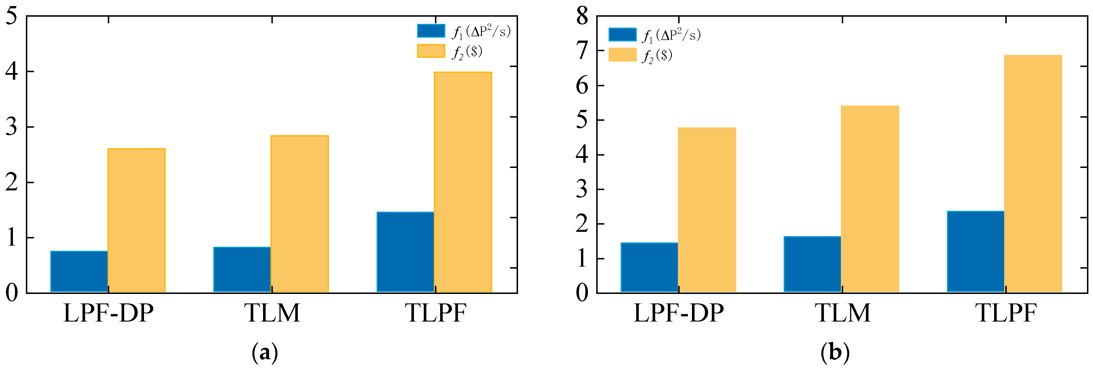
To validate the effectiveness of the proposed approach, a simulated load representing complex ship operating conditions was used for testing. Compared with the LPF, the proposed method reduces the fuel cell fluctuation rate by 44.06% and decreases the lithium battery capacity degradation cost by 28.9%, while achieving results that are closely aligned with those of offline optimization. Additionally, the real-time response time of the system is 9.1 ms, meeting the real-time requirements of a ship EMS. These results demonstrate that the proposed approach can provide efficient energy management in real-time applications, offering a novel energy management system for the real-time operation of the maritime industry.
A traditional real-time EMS relies on analyzing historical operational data and deriving allocation parameters through complex calculations, leading to rule-based solutions that are heavily dependent on these parameters. Such strategies struggle to adapt to diverse ship types and complex operating conditions. In contrast, the two-layer EMS proposed in this study bypasses the need for precise rule extraction from offline optimization and achieves outcomes closer to offline results. While designed for hydrogen-powered ships, the proposed EMS is adaptable to various vessels by utilizing their specific historical data. As more operational data are incorporated, the offline strategy library can expand, ensuring stable and reliable energy management under diverse cruising and environmental conditions.
This study has certain limitations that warrant further investigation. First, the proposed EMS does not fully address emergencies caused by environmental or human factors, such as sudden power fluctuations or unexpected equipment failures during ship operations. These challenges may impact the strategy’s effectiveness and stability in practical applications. Future research should focus on enhancing the adaptability of energy management strategies by simulating extreme scenarios and developing robust response mechanisms to ensure safe and reliable operation under complex and dynamic conditions.
Second, the EMS in this study is based on a single fuel cell and a hybrid energy storage system. However, modern ship power grids typically include multiple fuel cells and lithium-ion battery groups, which experience varying degrees of degradation over time. This non-uniform degradation can significantly affect the overall grid performance. Therefore, future work should explore coordination mechanisms for multiple fuel cell and battery groups while considering the impact of degradation on energy management strategies.


