Abstract
This study proposes a trajectory tracking approach for unmanned sailboats that integrates velocity and heading control using nonlinear model predictive control (NMPC). Unlike conventional methods, which typically rely on separate control strategies for maximum velocity and heading, this study employs a joint control framework based on NMPC. This approach allows for constrained control, ensuring that the sailboat operates safely at the desired velocity, forming a foundation for trajectory tracking. The trajectory tracking strategy, built on the joint control of velocity and heading, is further categorized into upwind and non-upwind tracking based on the wind direction. For non-upwind tracking, the desired heading is determined using the Line-of-Sight (LOS) navigation method, while the desired velocity is calculated through a backstepping method grounded in the Lyapunov stability theorem. For upwind tracking, a zigzag strategy is introduced, using the maximum lateral error to switch headings and ensure that the sailboat remains close to the trajectory. The simulation results show that the proposed method can effectively control the velocity and heading and realize accurate trajectory tracking of the unmanned sailboat under different wind conditions. The average error of velocity and heading control is close to zero. During trajectory tracking, the maximum control error is less than 0.35%.
1. Introduction
In recent years, underwater platforms, such as long-range autonomous underwater vehicles (AUVs), have been increasingly used for long-term, large-scale ocean exploration. However, their inability to communicate with shore-based systems while submerged requires them to periodically surface for communication and positioning, which reduces their detection capabilities and compromises stealth. Therefore, surface platforms must be employed to track and locate AUVs. Traditional surface vessels, however, may not be well-suited for matching the low velocity (usually 1–2 knots) and long range (over 2000 km) of an AUV [1]. Unmanned sailboats, which operate without batteries or fuel, are ideal for long-term research and tracking missions due to their ability to undertake journeys lasting hundreds of days [2]. As a result, they are particularly well-suited for long-term, extensive research and tracking missions, with significant applications in ocean exploration, development, and monitoring [3]. Therefore, the use of unmanned sailboats to track and locate AUVs offers a solution to this range mismatch. During the tracking process, velocity, heading, and trajectory control of the unmanned sailboat are necessary.
1.1. Current Status of the Research on Velocity and Heading Control
In the field of velocity and heading control of unmanned sailboats, almost all the literature designs two independent controllers for velocity control and heading control. The process typically begins with maximizing the velocity, which is primarily achieved by adjusting the sail angle without considering the impact of the rudder angle on speed. For maximum speed control, Xiao et al. [4] developed an extremum search (ES) algorithm to achieve the maximum velocity for unmanned sailboats on a specific heading. Corno et al. [5] introduced a feedback-optimized velocity controller that overcame modeling errors but faced steady-state oscillation issues. Zhipeng Shen et al. [6,7] developed a forward velocity optimization method using non-steady-state oscillation extremum search (ESWSO) to eliminate steady-state oscillations but with slower convergence. Later, they integrated sliding mode extremum seeking control (SMESC) with non-steady-state oscillation-free control (ESC) to achieve rapid velocity optimization, fast convergence, and high accuracy, though engineering validation is pending. Saoud et al. [8] proposed a constrained optimization approach that focused on sail propulsion force but neglected yaw moment effects, which could destabilize heading control. Stelzer et al. [9] developed a Mamdani-type fuzzy inference system for autonomous unmanned sailboat navigation, optimizing the velocity control by adjusting the sail angle based on the system’s execution frequency. Most research on velocity control has concentrated on maximizing the velocity as the primary objective by determining the optimal sail angle and adjusting it accordingly.
In heading control, after achieving the maximum velocity, the sail angle is first adjusted to its optimal position. Heading control is then achieved by adjusting the rudder angle, generating the required yaw moment to maintain or achieve the desired heading. This approach ensures that the sailboat follows its intended course while maintaining optimal speed. For heading control, Zhipeng Shen et al. [10] proposed a sliding mode dynamic surface control strategy that handled input constraints and disturbances using adaptive neural networks and Taylor expansions. Their method ensured smooth, robust heading control under dynamic uncertainties. Zhipeng Shen et al. [11] proposed a fuzzy logic-based sliding mode control method, enhancing the heading precision and stability against nonlinearities and disturbances, offering theoretical and engineering significance. Saoud et al. [12] designed a backstepping-based heading controller for unmanned sailboats, reducing the 6-DOF model to a 3-DOF bow control model. The heading control was further simplified to a second-order system, enabling effective heading regulation using the backstepping method. Xiao et al. [13] developed a 4-DOF model for heading control using integral inversion to design the control rates. A transverse mass block controlled the inclination angle, and the required turning moment was determined using backstepping. The rudder angle was calculated, but the method relied heavily on precise models for accuracy. Xiao et al. [14] proposed an L1 adaptive control method using a first-order Nomoto linear model to ensure stability and adaptability to uncertainties. The method included a state observer and low-pass filter to compensate for uncertainty, balancing the control performance and robustness. Stelzer et al. [9] developed a Mamdani-type fuzzy control for unmanned sailboat navigation. They divided heading, bow pitch rate, and rudder position into fuzzy sets, creating 15 rules. The center of gravity (CoG) method was used for defuzzification, enabling autonomous navigation and the precise control of the sailboat.
Their research employed decoupling strategies for velocity and heading regulation. First, maximum velocity control was performed for different headings to determine the optimal sail angle, and the sail was adjusted accordingly to ensure convergence to the maximum velocity. The heading was then controlled by adjusting the rudder angle. For applications such as tracking and positioning long-range AUVs, both velocity and heading control are crucial for unmanned sailboats. The strong coupling between the velocity and heading presents a challenge, as independently controlling the sail and rudder angles leads to frequent adjustments in the heading. To address this issue, this study utilizes NMPC as a unified controller for velocity and heading regulation.
1.2. Current Status of Path Tracking Research
As the surface communication node, unmanned sailboats must track the trajectory of the AUV to ensure the optimal communication distance and angle. Therefore, research on trajectory tracking control for unmanned sailboats is necessary. However, no relevant research has yet been conducted on the trajectory tracking control specifically for unmanned sailboats, highlighting a gap in the current literature.
A significant amount of the literature focuses on the trajectory tracking problem of unmanned sailboats, which can be seen as an improvement of the path-following problem aimed at achieving more precise control of the sailboat’s trajectory. Therefore, studying and improving the path-following methods for unmanned sailboats is essential. In terms of path-following control, Guoqing et al. [15] developed a composite integral LOS guidance method for path following under environmental disturbances, providing real-time heading references for upwind, downwind, and crosswind with good velocity regulation and low computational effort, suitable for maritime use. Jiqiang et al. [16] proposed an event-triggered robust adaptive control for unmanned sailboats under time-varying wind and input saturation. They used a proportional-integral sliding mode surface, robust neural damping, and auxiliary variables to reduce the communication burden and suppress the chattering caused by disturbances and system uncertainties. Dong et al. [17] proposed a Gaussian Process MPC (GPMPC) method for improving the navigation accuracy of unmanned sailboats. By decoupling the velocity and heading, they used an open-loop controller to adjust the sail angles for the maximum forward thrust. The heading controller incorporated LOS guidance and compensation for ocean currents, improving the accuracy and handling disturbances. Yingjie et al. [18] proposed two control modes for the reference path tracking of catamaran unmanned sailboats. One mode addressed tacking and jibing, while the second used a Serret–Frenet framework with LOS-based corrections. A fuzzy logic system and event-triggering mechanisms improved the control smoothness, with numerical experiments showing good performance. Yingjie et al. [19] proposed a parameterized LOS guidance method for the waypoint-based path tracking of unmanned sailboats, incorporating three modes: path tracking, upwind tacking, and downwind jibing. A yaw angle observer and dual RESO were used for accurate estimation in the lateral shifts. Adaptive neural network control and an echo state network (ESN) were employed for sail and rudder control, enhancing the robustness and learning efficiency.
Based on the investigation of unmanned sailboat path tracking, researchers commonly employ the LOS guidance method for path following. As an initial approach to implementing trajectory tracking control for unmanned sailboats, this study also utilized the LOS guidance method for trajectory tracking control. First, the expected heading was determined using LOS guidance. After obtaining the expected heading, the Lyapunov function was applied to design the expected velocity using the backstepping method. The velocity and heading are then jointly controlled through NMPC.
During the trajectory tracking process, unmanned sailboats cannot obtain thrust or control velocity when sailing in the dead zone against the wind. The dead zone diagram is shown in Figure 1. According to the speed polar coordinate curve, there is a heading interval where the speed drops extremely rapidly, and this interval is called the dead zone. If the tracking trajectory falls within this dead zone, the expected heading must first be adjusted to ensure that the unmanned sailboat avoids entering the sailing dead zone. The expected velocity must be designed to reduce the longitudinal error to zero, although the lateral error cannot be guaranteed to reach zero. A lateral error boundary was designed to ensure that the deviation from the desired trajectory does not become excessively large while also preventing the unmanned sailboat from frequently switching headings.
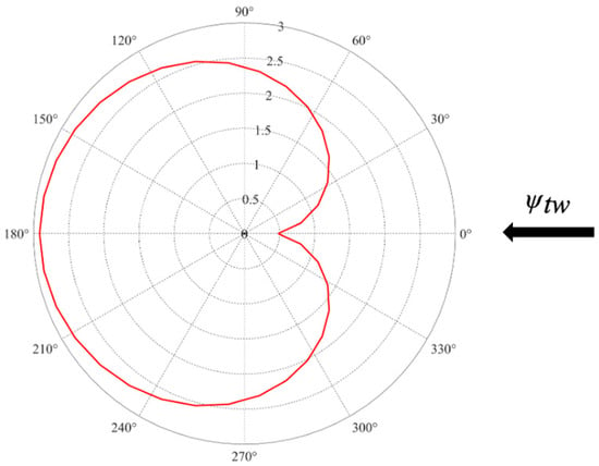
Figure 1.
The dead zone diagram.
The main contributions of this study are summarized as follows:
- (1)
- This paper proposes a velocity and heading joint control method for unmanned sailboats based on NMPC to address the coupling between control inputs. It ensures the joint control of the velocity and heading while accounting for the state constraints. The NMPC method is well-suited for solving coupled control problems and effectively handles the optimization problems with constraints.
- (2)
- This paper proposes a straight-line trajectory tracking method for unmanned sailboats based on LOS guidance and Lyapunov stability theory. The method calculates the sailboat’s speed and heading required for straight-line trajectory tracking and realizes the tracking of both velocity and heading using the NMPC-based joint control method.
- (3)
- This paper proposes a Z-shaped upwind trajectory tracking strategy with lateral error constraints, ensuring that the longitudinal error converges to zero while the lateral error remains within the defined range. The designed maximum allowable lateral error prevents the unmanned sailboat from straying too far from the trajectory and minimizes frequent heading changes.
The remainder of this study is organized as follows. In Section 2, a 4-DOF dynamic equation is presented. In Section 3, a specific algorithm for NMPC-based velocity and heading joint control is proposed. In Section 4, a trajectory tracking method based on LOS guidance and an inverse step method, derived from the Lyapunov stability theorem, are proposed. In Section 5, numerical simulations are used to verify the proposed methods. Finally, in Section 6, a summary is provided, and future research prospects are discussed.
2. Dynamic Model of Unmanned Sailboats
A mathematical model of unmanned sailboat motion forms the foundation for studying its maneuverability and motion control [20]. Ship motion modeling typically includes identification and mechanism modeling, with mechanism modeling being the dominant approach in the field. The most representative mathematical models of ship motion obtained from mechanism modeling include the overall models represented by the Abkowitz model [21] and the Norrbin model [22], as well as a separate model, the ship maneuvering mathematical model group (MMG) model [21]. For unmanned sailboats, the application of the MMG model incorporates the effect of sails into the existing ship model, significantly reducing the development complexity. Zhipeng et al. [23] established a 4-DOF wind-sail-assisted ship motion model based on the MMG model and conducted a simulation analysis of ship motion; however, the main driving force in this model was still the propeller, making it less suitable for unmanned sailboats. Xiao et al. [14] divided sailboats into four components—wind sails, rudders, keels, and hulls—and analyzed the forces on each part using fluid mechanics. They established a 4-DOF sailboat model based on the MMG model, with the parameters identified through experimental methods.
This paper focuses on a single unmanned sailboat, where the roll angle significantly influences the navigation performance. To prevent capsizing, the control algorithm restricts the heel angle. Thus, by leveraging a 3-DOF dynamic model, this study incorporates the heel angle, resulting in a 4-DOF model for control investigations.
Xiao et al. [13] provided a detailed description of the 4-DOF dynamics of unmanned sailboats, which is widely referenced in most of the research literature using 4-DOF dynamics models. Therefore, this paper adopts the 4-DOF dynamics model proposed by them. The schematic diagram of the 4-DOF model is shown in Figure 2.
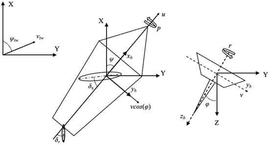
Figure 2.
Schematic diagram of unmanned sailboat model.
In this paper, their dynamics model formula is expanded using a matrix to obtain the mathematical expression, presented in the form of Equation (1):
where u, v, p, and r are the surge, sway, roll angular, and yaw angular velocities, respectively, and m denotes the total mass of the sailboat. and are the additional surge and sway masses, and are the surge and heave moments of inertia, and are the additional moments of inertia, and use i = s, r, h, and k to represent the forces on the sail, rudder, hull, and keel in terms of surge and sway, and and use i = s, r, h, and k to represent the roll and yaw moment components. The constants a, b, c, and d are derived from yacht inclining tests.
An MMG 4-DOF sailboat model was adopted to establish an accurate unmanned sailboat model, with comprehensive consideration given to the environmental disturbances such as wind and waves. Parameter calculations were performed using empirical formulas and computational fluid dynamics (CFD) methods, resulting in a dynamic model of the unmanned sailboat. The detailed mathematical equations and parameters of the unmanned sailboat dynamic model can be found in Appendix A.
The kinematic model of an unmanned sailboat is
where x, y, φ, and ψ represent the position, roll, and yaw in the inertial frame.
3. NMPC-Based Velocity and Heading Control of Unmanned Sailboats
The velocity and heading control for unmanned sailboats pose constrained control challenges due to the navigational constraints. Additionally, the strong coupling between sail and rudder control, along with the system’s inherent nonlinearity, necessitates the use of NMPC for effective regulation.
3.1. Introduction of NMPC
NMPC [24] is a closed-loop optimization control strategy based on a nonlinear model. While linear predictive models can adequately approximate the dynamic processes of systems with weak nonlinearity, and linear predictive control often performs well in such cases, they struggle with strongly nonlinear systems. Linear models have difficulty accurately describing the complex dynamic processes in highly nonlinear systems, making it difficult to apply linear predictive control. Therefore, NMPC was proposed as a solution to effectively handle these nonlinear dynamics.
The core of the MPC algorithm involves solving an open-loop optimization problem over a finite time horizon at each sampling period. Starting from the current state of the system, an optimal control sequence is derived, and the first control input from this sequence is applied to the system, forming a rolling optimization strategy over the finite time domain. This approach is particularly well-suited for solving optimization problems with state constraints.
For unmanned sailboats, there are numerous physical constraints during motion, and a high degree of coupling exists between the two control inputs (sail and rudder). The model is highly nonlinear, making linearization complex and prone to significant errors. Therefore, NMPC is a preferable choice for addressing these challenges effectively.
3.2. Velocity and Heading Control of an Unmanned Sailboat Based on NMPC
Due to the dead zone in sailboat navigation control, unmanned sailboats cannot obtain propulsion or perform velocity and heading control while within the dead zone. Therefore, only situations outside the dead zone were considered for the velocity and heading control of unmanned sailboats. The control diagram illustrating this process is shown in Figure 3.
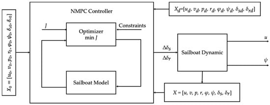
Figure 3.
Diagram of velocity and heading control of unmanned sailboat.
The state variables were determined based on the 4-DOF dynamic and kinematic models of the unmanned sailboat. The unmanned sailboat controls its velocity by adjusting the sail angle and its heading by adjusting the rudder angle, making the control variables the sail angle and rudder angle . Thus, the control input is defined as . Due to the mechanical limitations of the rudder motor, there are physical constraints on the motion velocity of the rudder motor, resulting in limitations on the rates of change for both the sail and rudder angles. To better reflect the real-world conditions and enhance control, this study used the rates of change of the sail angle and rudder angle as the control variables, i.e., . Therefore, the state variables were rewritten as . And then, Equation (1) can be rewritten as:
3.2.1. Optimization Function
The objective function was designed to ensure the tracking of the desired velocity and heading by accounting for the output error, control input, and control input increment. The stability of NMPC was maintained by incorporating terminal constraints into the optimization objective function. Therefore, the objective function was designed as follows:
where P, Q, and R denote the weight matrices; Np represents the prediction horizon; and and are the actual and expected states from time k for the next k + i steps, respectively. And represents the state at the moment in the prediction time domain.
3.2.2. Constraints
An unmanned sailboat relies on external wind for propulsion and is constrained by a maximum forward velocity under varying headings. In addition, the velocity of the sailboat must remain greater than zero to prevent inversion. Therefore, the velocity constraint is
To prevent capsizing and ensure that both sides of the hull remain above the water, a constraint on the roll angle is necessary. Since the sailboat hull is symmetrical along the centerline, the constraint on the roll angle can be expressed as
where is the roll angle when the sailboat is completely immersed on the starboard side.
Owing to dead zones during navigation where unmanned sailboats cannot generate power, a constraint is necessary to limit the angle ψe between the heading angle and the true wind direction to remain outside the dead zone. This constraint can be expressed as
where is the maximum angle in the navigable area when , and is the minimum angle in the navigable area when . A schematic of this process is shown in Figure 4.
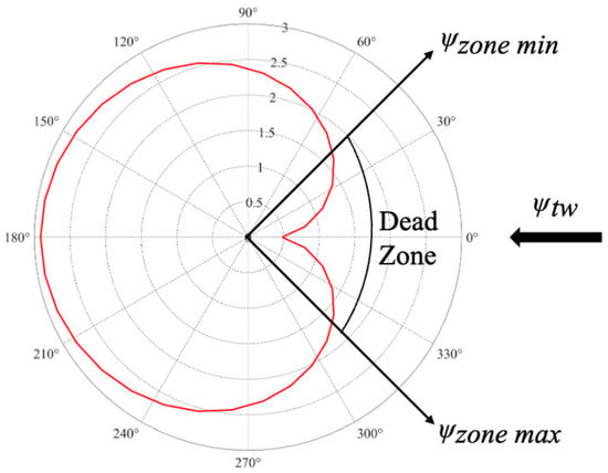
Figure 4.
Constraint diagram [25].
The motion range of the sail angle and rudder angle in the control of an unmanned sailboat is limited and must satisfy the following constraint conditions.
The control of an unmanned sailboat requires constraints on the sail angle and rudder angle to ensure that they remain within the specified motion ranges. This constraint can be expressed as
Moreover, due to the motorized control of the sails and rudder on unmanned sailboats, the rates of change in the sail angle () and rudder angle () must comply with the motion constraints of the motors. These constraint conditions are expressed as follows:
Therefore, the control objectives of the NMPC for unmanned sailboat velocity and heading control are as follows:
s.t.
Adjusting the weight matrices P, Q, and R ensures convergence to the desired velocity and heading.
3.2.3. Discretization
MPC is a computer-based control method. NMPC requires solving a constrained nonlinear optimization problem at each control interval, which often lacks an analytical solution and must be computed numerically. Therefore, the prediction model used in MPC must first be discretized.
In discretization, Euler’s method and the Runge–Kutta method are commonly applied. Euler’s method offers faster computation but lower accuracy compared to the Runge–Kutta method, while also requiring fewer computational resources. Due to these advantages, Euler’s method is more suitable for physical ship applications. Hence, this study employs Euler’s method for discretization. For the nonlinear state control equation of unmanned sailboats , with the current state value X(k), the next state is solved using Euler’s method as follows:
4. Trajectory Tracking Control of Unmanned Sailboats
Due to the existence of dead zones during the navigation of unmanned sailboats, this study addresses the trajectory tracking in two situations: outside and inside the dead zones. The trajectory tracking method is based on the LOS guidance method, which calculates the expected velocity and heading for effective control in both situations.
4.1. Trajectory Tracking Method Outside the Dead Zone
When the expected trajectory is outside the dead zone, assuming that the expected trajectory is , the LOS guidance method is used for trajectory tracking control. The geometric relationship of each parameter in the LOS guidance method is shown in Figure 5. Assuming that the expected trajectory is in the body-fixed coordinate system and the angle between the positive direction of the -axis and the positive north direction is , the lateral tracking error (the -axis coordinate value) and longitudinal tracking error (the -axis coordinate value) in the body coordinate system are denoted as and , respectively. Based on the position error in the geodetic coordinate system XOY, the following equation is obtained:
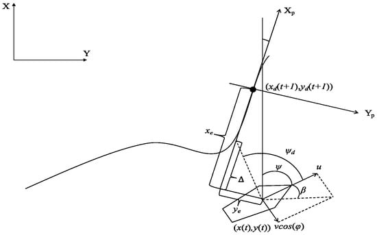
Figure 5.
Geometric relationship of each parameter in LOS guidance method.
The derivatives of and are
By substituting into the kinematic equation for an unmanned sailboat, we obtain
According to the geometric relationships in the LOS guidance method, . Due to the existence of lateral velocity v, there is a yaw angle β between the expected heading and the expected bow heading . By setting , , , we obtain
where is the velocity of the trajectory point’s forward line.
To ensure the convergence of the lateral error , the reference heading angle for the LOS guidance design is
We assume that the unmanned sailboat can track the expected heading, i.e., . The backstepping method is used to design the expected velocity based on the Lyapunov stability theorem. The Lyapunov function is defined as
The derivatives with respect to time are
To ensure system stability,
where and are positive constants. The expected combined velocity of the unmanned sailboat is given by the following equation:
Thus, the desired forward velocity is
To perform velocity and heading control, and are used as the desired values for the velocity and heading control system, respectively. Since an unmanned sailboat relies on wind energy for propulsion, its velocity depends on the wind conditions, and a maximum velocity exists under different wind velocities and directions. Therefore, when the expected velocity exceeds the maximum velocity calculated using the aforementioned algorithm, was set to . This ensures that the lateral error converges to zero.
To ensure that the lateral error converged to 0, we took . Therefore,
4.2. Trajectory Tracking in the Sailing Dead Zone
When the expected heading obtained from the LOS guidance and the wind direction angle fall within the sailing dead zone, the unmanned sailboat will enter this zone and lose control if it attempts to reach the expected heading.
To address this problem, a zigzag tracking strategy with lateral error limits was adopted for trajectories within the sailing dead zone. A sailing corridor with an allowable lateral error d was designed, and the sailboat’s heading was adjusted when it reached the error boundary, ensuring that the longitudinal error remained zero.
If , the zigzag tracking strategy was employed to guide the unmanned sailboat along the boundary of the dead zone, i.e., . However, to account for the overshoot phenomenon during the heading adjustment process and to avoid the heading from entering the dead zone, which would result in velocity decay, the desired heading of the unmanned sailboat was designed as , where θ is the maximum overshoot during the heading adjustment process.
If , then . During the movement along this heading, if , the sailboat needs to turn, and then . If , then . If , the sailboat needs to turn, and then . Here, is the expected heading angle when entering the navigation dead zone for the first time. The navigation diagram is shown in Figure 6.
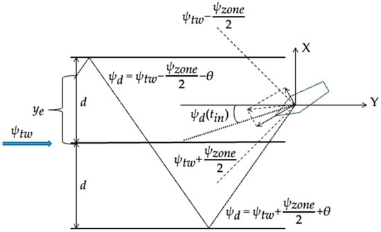
Figure 6.
Navigation diagram of trajectory tracking in sailing dead zone.
To ensure that the longitudinal error xe converged to zero, a Lyapunov stability analysis was applied to determine the expected forward velocity of the unmanned sailboat. It was assumed that the course of the unmanned sailboat could converge to ; that is, . Consider the following Lyapunov function:
Then the derivative of V with respect to time is
To ensure global asymptotic stability, ; then,
Thus, the desired forward velocity is
Based on the contents of the above two sections, a flowchart is created to illustrate the control process. Figure 7 presents the overall control process for unmanned sailboat trajectory tracking, while Figure 8 provides a detailed breakdown of the navigation module within this process, covering both non-upwind and upwind trajectory tracking.

Figure 7.
Overall control process of unmanned sailboat trajectory tracking.
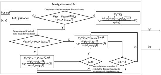
Figure 8.
Specific content of navigation module in overall process.
5. Simulation Results
This study used the “Seagull”, an unmanned sailboat developed by the Shenyang Institute of Automation, Chinese Academy of Sciences, as the subject of numerical simulation research (hereinafter referred to as the unmanned sailboat). The unmanned sailboat had a total length of 3.5 m. A three-dimensional model and picture are shown in Figure 9. The primary components of the sailboat included the hull, keel, sail, rudder, and ballast. A keel was installed at the bottom of the hull to ensure the stability of the sailboat.

Figure 9.
Three-dimensional model and picture of seagull unmanned sailboat.
5.1. Results of Velocity and Heading Coordinated Control Based on NMPC
5.1.1. Comparison of Velocity and Heading Control: NMPC, PID, and MPC Under Constant Wind Conditions
In this subsection, a comparison is made between the NMPC-based velocity-heading coordinated control methods, MPC and PID, using a sampling time T = 0.1 s; initial conditions ; steady wind conditions = 12 m/s, = 0°; desired velocity = 1 m/s; and = 130°. The expected values of other states were all 0. The weight matrices for NMPC were P = [1; 0; 0; 0; 5; 16; 0; 0], Q = [0.01; 0.0001], and R = [5; 0; 0; 0; 15; 25; 0; 0]; for MPC, the weight matrices were P = [25; 10; 0; 0; 5; 10; 0; 10], Q = [0; 0.0001], and R = [5; 0; 0; 0; 0; 10; 0; 10]. The parameters for the PID velocity controller were set as P = 0.0001, with I = D = 0, while the parameters for the PID heading controller were set as P = 0.6, with I = D = 0.
The motion constraint parameters are shown in Table 1, and the main parameter configuration is shown in Table 2.

Table 1.
The motion constraint parameters.

Table 2.
The main parameter configuration.
MATLAB, along with the Casadi solver, was used to conduct a 200 s simulation experiment for both NMPC and MPC, while Simulink was employed for the simulation experiment using PID control. The simulation results are displayed in Figure 10, and a comparison of the simulation outcomes is presented in Table 3.
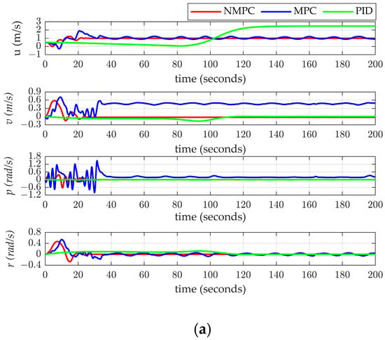
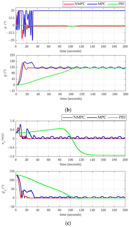
Figure 10.
(a) Velocity results for three control methods. (b) Results of three control methods on attitude. (c) Control error results for three methods.

Table 3.
Comparison of simulation results for the two methods.
When using joint control of velocity and heading based on NMPC, the unmanned sailboat was able to achieve near zero-error control under constrained conditions, as shown in the simulation results. The maximum velocity error during the stable phase was 0.01 m/s, and the maximum heading error was 0.04°. In contrast, the MPC-based joint control method for velocity and heading encountered substantial errors due to discrepancies between the linear prediction model and the nonlinear actual model. This mismatch resulted in persistent jitter and a heel angle consistently at the maximum constraint, with the sailboat having a heel angle of 25.00°, indicating a constant risk of flooding. The average velocity error during stability was 0.47 m/s, and the average heading error was 4.05°, demonstrating the inability of MPC to achieve precise joint control of both velocity and heading. In the case of PID-based velocity and heading control, two separate PID controllers were designed to manage the velocity and heading independently. However, the strong coupling between the sail and rudder controls made it highly challenging to adjust both controllers simultaneously. Therefore, priority was given to ensuring the accuracy and stability of heading control, while velocity error was largely disregarded. This led to a heading control error of 0° but a velocity control error of −1.48 m/s. Compared to the MPC and PID methods, the NMPC-based method not only successfully achieved constrained joint control of both velocity and heading but also exhibited faster velocity stabilization, smaller errors, and improved stability.
5.1.2. Velocity–Heading Coordinated Control of Unmanned Sailboats Based on NMPC Under Variable Wind Conditions
For variable wind conditions, the wind velocity was , and the wind direction was , where t denotes the simulation time and ω is the random number between 0 and 1. From 0 to 100 s, the desired velocity was , and the desired heading was . From 100 to 200 s, the desired velocity was , and the desired heading was . From 200 to 300 s, the desired velocity was , and the desired heading was . The expected values of other states were all 0. The initial state of the sailboat was , with a weight matrix , , and . The sampling time for NMPC was T = 0.1 s, and the prediction horizon was = 30. The main parameter configuration is shown in Table 4. The simulation results are shown in Figure 11.

Table 4.
The main parameter configuration.
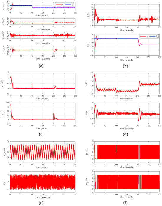
Figure 11.
(a) Velocity variation curve. (b) Attitude variation curve. (c) Error variation curve. (d) Sail angle and rudder angle variation curve. (e) Wind direction and speed variation curve. (f) Sail and rudder angle change rate curve.
Based on the simulation results, velocity–heading coordinated control using NMPC can successfully achieve velocity and heading coordination under variable wind conditions. The key data for the stable phase of the simulation are presented in Table 5, Table 6 and Table 7.

Table 5.
Key data of ud = 1.5 m/s and ψd = 90°.

Table 6.
Key data of ud = 1 m/s and ψd = 90°.

Table 7.
Key data of ud = 1 m/s and ψd = 50°.
According to the simulation results, the velocity and heading joint control algorithm based on NMPC can achieve effective control under conditions of sine wave fluctuations and the random superposition of wind changes. The average velocity error was approximately 0.01 m/s, and the average heading error was less than 0.5°, demonstrating excellent control performance and stability.
5.2. Trajectory Tracking Results
AUVs use a comb-like search strategy during mineral exploration. Similarly, an unmanned sailboat follows a comb-like trajectory when tracking an AUV. In this study, a sailboat designed to track a comb-like trajectory was designed. The wind velocity was and the wind direction was , where t denotes the simulation time, and ω is the random number between 0 and 1. The initial state of the unmanned sailboat was . The expectations of other state variables except the expected velocity and expected heading were all 0. The weight matrices were , , and . The forward distance was , with constants and . The NMPC sampling time was T = 0.1 s, and the prediction horizon was . The simulation time for trajectory tracking was 3000 s, with the trajectory starting from the origin. From 0 to 1000 s, the trajectory advanced with speed and direction . From 1000 to 2000 s, the trajectory advanced with speed and direction . From 2000 to 3000 s, the trajectory advanced with speed and direction . Thus,
The main parameter configuration is shown in Table 8. MATLAB was used for the simulations. The simulation results are shown in Figure 12, Figure 13 and Figure 14, and the key data are listed in Table 9.

Table 8.
The main parameter configuration.
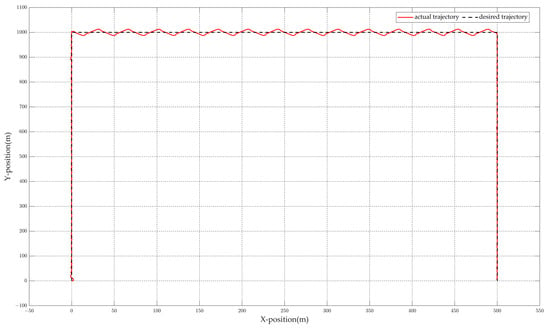
Figure 12.
Trajectory tracking results under variable wind conditions.

Figure 13.
(a) Velocity variation curve. (b) Position and attitude change curves. (c) Trajectory tracking lateral error and longitudinal error.
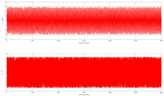
Figure 14.
Curves of changes in wind speed and direction.

Table 9.
Key data of trajectory tracking.
According to the simulation results, from 0 to 1000 s, the starboard side of the sailboat faced the wind. During the trajectory tracking process, the maximum longitudinal tracking error was 4.63 m, the minimum longitudinal tracking error was 0, the maximum lateral tracking error was 2.32 m, and the minimum lateral tracking error was 0. The maximum overall tracking distance error was 5.18 m, with a minimum of 0.01 m and an average of 0.72 m. Owing to the changes in wind speed and direction during the tracking process, the unmanned sailboat experienced some jitter while tracking the speed and heading, leading to tracking errors. However, when compared with the total movement distance of 1000 m, the average distance error was only 0.07%, which is acceptable for practical applications.
From 1000 to 2000 s, the sailboat moved against the wind, adopting a Z-shaped trajectory. The designed maximum lateral distance from the trajectory was 10 m, but the actual lateral distance was 12.80 m. During the trajectory tracking process, the maximum longitudinal tracking error was 3.28 m, and the minimum longitudinal tracking error was 0.45 m. The maximum lateral tracking error was 12.80 m, and the minimum lateral tracking error was 0 m. The maximum overall tracking distance error was 12.89 m, with a minimum of 0.47 m and an average of 7.38 m. In the upwind trajectory tracking phase, only the longitudinal tracking error was considered. Due to the changes in wind speed and direction during the tracking, the unmanned sailboat experienced jitter while tracking the speed and heading, resulting in tracking errors. However, compared to the total movement distance of 500 m, the average longitudinal tracking error was only 0.35%, which is acceptable for practical applications.
From 2000 to 3000 s, the port side of the sailboat faced the wind. During the trajectory tracking process, the maximum longitudinal tracking error was 2.31 m, and the minimum was 0. The maximum lateral tracking error was 1.65 m, while the minimum was 0. The overall maximum tracking distance error was 2.53 m, with a minimum of 0.01 m and an average of 0.56 m. Due to the changes in wind speed and direction during the tracking process, the unmanned sailboat experienced some jitter while tracking the speed and heading, leading to tracking errors. However, when compared with the total movement distance of 1000 m, the average distance error was only 0.06%, which is acceptable for practical applications.
Therefore, the proposed trajectory tracking method, based on LOS guidance and the upwind Z-shaped strategy, effectively improves the trajectory tracking control of unmanned sailboats.
6. Summary and Outlook
In this study, we achieved the joint control of the velocity and heading of an unmanned sailboat, as well as trajectory tracking. For velocity and heading control, a 4-DOF mathematical model of an unmanned sailboat accounting for rolling motion was established. Based on this model, the sail and rudder were jointly controlled using the NMPC method, enabling the joint control of both the sailboat’s velocity and heading.
The study of trajectory tracking was divided into two scenarios due to the existence of an upwind sailing dead zone: non-upwind and upwind sailing. For non-upwind tracking, LOS-based heading and Lyapunov-based velocity were tracked using NMPC control, achieving effective trajectory tracking. For upwind tracking, a zigzag strategy was applied when the expected LOS-based heading fell within the dead zone, ensuring that the errors remained within bounds. Simulations confirmed the accuracy of the proposed control method and strategy.
This study focused on the joint control of speed and heading, as well as linear trajectory tracking under changing wind conditions. Other environmental factors, such as waves and currents, were not considered, and the curved trajectory tracking of sailboats was not studied. In subsequent work, we will also study the handling of rapidly changing environmental interference, the impact of changing parameters on system performance, energy consumption analysis, and control methods in other application scenarios to address the issues that have not been studied in this study.
Author Contributions
Conceptualization, K.L. and J.Y.; Methodology, K.L. and J.Y.; Software, K.L.; Validation, K.L.; Formal analysis, W.Z.; Investigation, K.L.; Resources, W.Z.; Data curation, K.L.; Writing—original draft, K.L.; Writing—review & editing, J.Y. and W.Z.; Project administration, J.Y.; Funding acquisition, J.Y. and W.Z. All authors have read and agreed to the published version of the manuscript.
Funding
This study was supported by the National Natural Science Foundation of China (General Program, 42276198) and the Youth Innovation Promotion Association CAS (NO. 2023212).
Institutional Review Board Statement
Not applicable.
Informed Consent Statement
Not applicable.
Data Availability Statement
The data presented in this study are available on request from the authors.
Conflicts of Interest
The authors declare no conflict of interest.
Appendix A. The Specific Expressions and Parameter Meanings
According to the reference [25], the specific expressions and parameter meanings are as follows:
where:
; ; ; ; ; ; ; , .
u and v represent the velocity in the forward and lateral directions of the body coordinate system, respectively (m/s), while p and r represent the roll and pitch angular velocities of the body coordinate system, respectively (rad/s). ϕ represents the roll angle of the body coordinate system (rad), ψ represents the heading angle of the earth coordinate system (rad), and x and y represent the position of the sailboat in the earth coordinate system (m). vtw represents the true wind speed (m/s), αtw represents the true wind direction (rad), δs represents the sail angle (rad), and δr represents the rudder angle (rad). arctan2 is the four-quadrant inverse tangent function. The research subject is the “Seagull” unmanned sailboat, developed by the Shenyang Institute of Automation, Chinese Academy of Sciences. The meanings and values of each parameter are shown in Table A1.

Table A1.
The meanings and values of the parameters in this study.
Table A1.
The meanings and values of the parameters in this study.
| Parameter Description | Parameter Name | Value |
|---|---|---|
| Mass | Total mass /kg | 230 |
| Parameters affecting roll stability | Initial stability height | 0.32 |
| Sail, rudder, and keel area (used to calculate the lift and drag) | Sail reference area /m2 | 1.6 |
| Rudder reference area /m2 | 0.048 | |
| Keel reference area /m2 | 0.127 | |
| The position in the body coordinate system (origin at the sailboat center of gravity) | Sail (xs, ys, zs)/m Rudder (xr, yr, zr)/m Keel (xk, yk, zk)/m Hull (xh, yh, zh)/m Mast x-coordinate xm/m | (0.56, 0, −1.65) |
| (−1.6, 0, −0.08) | ||
| (−0.09, 0, −0.25) | ||
| (0.11, 0, −0.2) | ||
| 0.29 | ||
| Yaw damping | d | 100 |
| Roll damping | BL | 117.72 |
| BN | 10.93 | |
| Airfoil coefficient (used to calculate the lift and drag) | Sail kcs | 1.8 |
| Rudder kcr | 2.2 | |
| Keel kck | 1.5 | |
| Sailboat resistance curve coefficient | p1 | 0.09721 |
| p2 | 3.041 | |
| Correction coefficient | 6.23 | |
| Constants | Air density /(kg/m3) | 1.2 |
| Sea water density /(kg/m3) | 1025 | |
| g/(m/s2) | 9.81 | |
| Inertial mass parameter | 832.50 | |
| 44.92 | ||
| −23.00 | ||
| −117.01 | ||
| −11.74 | ||
| −172.91 | ||
| −8.74 |
References
- Huang, Y.; Wang, Z.; Yu, J.; Zhang, A.; Qiao, J.; Feng, H. Development and Experiments of the Passive Buoyancy Balance System for Sea-Whale 2000 AUV. In Proceedings of the OCEANS 2019-Marseille, Marseille, France, 17–20 June 2019. [Google Scholar]
- An, Y.; Yu, J.; Zhang, J. Autonomous sailboat design: A review from the performance perspective. Ocean. Eng. 2021, 238, 16. [Google Scholar] [CrossRef]
- Tipsuwan, Y.; Sanposh, P.; Techajaroonjit, N. Overview and control strategies of autonomous sailboats—A survey. Ocean Eng. 2023, 281, 114879. [Google Scholar] [CrossRef]
- Xiao, L.; Alves, J.C.; Cruz, N.A.; Jouffroy, J. Online speed optimization for sailing yachts using extremum seeking. In Proceedings of the 2012 Oceans, Hampton Roads, VA, USA, 14–19 October 2012. [Google Scholar]
- Corno, M.; Formentin, S.; Savaresi, S.M. Data-Driven Online Speed Optimization in Autonomous Sailboats. IEEE Trans. Intell. Transp. Syst. 2016, 17, 762–771. [Google Scholar] [CrossRef]
- Shen, Z.; Wang, S.; Yu, H.; Guo, C. Online speed optimization with feedforward of unmanned sailboat via extremum seeking without steady-state oscillation. Ocean Eng. 2019, 189, 106393. [Google Scholar] [CrossRef]
- Shen, Z.; Fan, X.; Yu, H.; Guo, C.; Wang, S. A novel speed optimisation scheme for unmanned sailboats by sliding mode extremum seeking control without steady-state oscillation. J. Navig. 2022, 75, 745–762. [Google Scholar] [CrossRef]
- Saoud, H.; Hua, M.-D.; Plumet, F.; Ben Amar, F. Optimal sail angle computation for an autonomous sailboat robot. In Proceedings of the 54th IEEE Conference on Decision and Control (CDC), Osaka, Japan, 15–18 December 2015. [Google Scholar]
- Stelzer, R.; Proll, T.; John, R.I. Fuzzy Logic Control System for Autonomous Sailboats. In Proceedings of the IEEE International Fuzzy Systems Conference, London, UK, 23–26 July 2007. [Google Scholar]
- Shen, Z.P.; Zou, T.Y.; Guo, T.T. Adaptive dynamic surface control for nonaffine unmanned sailboat course system with input constraint. Control Theory Technol. 2019, 36, 1461–1468. [Google Scholar]
- Shen, Z.P.; Zhang, X.L. Iterative sliding mode control over sail-assisted ship course based on adaptive heuristic critic algorithm. J. Harbin Eng. Univ. 2017, 38, 1727–1732. [Google Scholar]
- Saoud, H.; Hua, M.D.; Plumet, F.; Ben Amar, F. Modeling and Control Design of a Robotic Sailboat. In The 6th International Robotic Sailing Conference; Springer Publishing Company, Incorporated: Princeton, NJ, USA, 2013; pp. 95–110. [Google Scholar]
- Xiao, L.; Jouffroy, J. Modeling and Nonlinear Heading Control of Sailing Yachts. IEEE J. Ocean. Eng. 2014, 39, 256–268. [Google Scholar] [CrossRef]
- Xiao, L.; Fossen, T.I.; Jouffroy, J. Nonlinear Robust Heading Control for Sailing Yachts. IFAC Proc. Vol. 2012, 45, 404–409. [Google Scholar] [CrossRef]
- Zhang, G.; Li, J.; Liu, C.; Zhang, W. A robust fuzzy speed regulator for unmanned sailboat robot via the composite ILOS guidance. Nonlinear Dyn. 2022, 110, 2465–2480. [Google Scholar] [CrossRef]
- Li, J.; Zhang, G.; Zhang, X.; Zhang, W. Event-triggered robust adaptive control for path following of the URS in presence of the marine practice. Ocean. Eng. 2021, 242, 110139. [Google Scholar] [CrossRef]
- Dong, Y.; Wu, N.; Qi, J.; Chen, X.; Hua, C. Predictive Course Control and Guidance of Autonomous Unmanned Sailboat Based on Efficient Sampled Gaussian Process. J. Mar. Sci. Eng. 2021, 9, 1420. [Google Scholar] [CrossRef]
- Zhang, G.; Li, J.; Li, B.; Zhang, X. Improved Integral LOS Guidance and Path-Following Control for an Unmanned Robot Sailboat via the Robust Neural Damping Technique. J. Navig. 2019, 72, 1378–1398. [Google Scholar] [CrossRef]
- Deng, Y.; Zhang, X.; Zhang, G. Line-of-Sight-Based Guidance and Adaptive Neural Path-Following Control for Sailboats. IEEE J. Ocean. Eng. 2019, 45, 1177–1189. [Google Scholar] [CrossRef]
- Zhao, B.G.; Zhang, X.K.; Li, Z.; Liang, C.L. Research on ship motion identification modeling. Ship Sci. Technol. 2021, 43, 4. [Google Scholar]
- Yasukawa, H.; Yoshimura, Y. Introduction of MMG standard method for ship maneuvering predictions. J. Mar. Sci. Technol. 2015, 20, 37–52. [Google Scholar] [CrossRef]
- Zhang, X.; Yang, G. Improvement of Nonlinear Norrbin Mathematical Model for Large Ships. Navig. Tion China 2016, 39, 4. [Google Scholar]
- Shen, Z.-P.; Jiang, Z.-H. Motion model of sail-assisted ship. J. Traffic Transp. Eng. 2015, 15, 57–64. [Google Scholar] [CrossRef]
- Grne, L.; Pannek, J. Nonlinear Model Predictive Control: Theory and Algorithms; Springer Publishing Company, Incorporated: Princeton, NJ, USA, 2013. [Google Scholar]
- Liu, K.; Yu, J.; Zhao, W.; Huang, Y. Speed and heading joint control of an unmanned sailboat based on NMPC. In Proceedings of the 3rd International Conference on Control and Intelligent Robotics (ICCIR 2023), Sipsongpanna, China, 1 December 2023; SPIE: Bellingham, WA, USA, 2023. [Google Scholar]
Disclaimer/Publisher’s Note: The statements, opinions and data contained in all publications are solely those of the individual author(s) and contributor(s) and not of MDPI and/or the editor(s). MDPI and/or the editor(s) disclaim responsibility for any injury to people or property resulting from any ideas, methods, instructions or products referred to in the content. |
© 2024 by the authors. Licensee MDPI, Basel, Switzerland. This article is an open access article distributed under the terms and conditions of the Creative Commons Attribution (CC BY) license (https://creativecommons.org/licenses/by/4.0/).