Article

Fixed-Time Path-Following-Based Underactuated Unmanned Surface Vehicle Dynamic Positioning Control

Science and Technology on Underwater Vehicle Laboratory, Harbin Engineering University, Harbin 150001, China
*
Author to whom correspondence should be addressed.
J. Mar. Sci. Eng. 2024, 12(4), 551; https://doi.org/10.3390/jmse12040551
Submission received: 6 February 2024 / Revised: 5 March 2024 / Accepted: 12 March 2024 / Published: 26 March 2024
(This article belongs to the Special Issue Control and Navigation of Underwater Robot Systems)

Abstract

:
The development of dynamic positioning (DP) algorithms for an unmanned surface vehicle (USV) is attracting great interest, especially in support of complex missions such as sea rescue. In order to improve the simplicity of the algorithm, a DP algorithm based on its own path following control ability is proposed. The algorithm divides the DP problem into two parts: path generation and path following. The key contribution is that the DP ability can be realized only by designing the path generation method, rather than a whole complex independent DP controller. This saves the computing power of the USV onboard computer and can effectively reduce the complexity of the algorithm. In addition, the fixed-time LOS guidance law is designed to improve the convergence rate of the system state in path-following control. The reasonable selection of speed and a heading controller ensures that the number of design parameters to be determined is at a low level. The above algorithms have been thoroughly evaluated and validated through extensive computer simulations, demonstrating their effectiveness in simulated and real marine environments. The simulation results verify the ability of the proposed algorithm to realize the dynamic positioning of USVs, and provide a practical scheme for the design of the dynamic positioning controller of USVs.

1. Introduction

As typical underactuated systems, unmanned surface vehicles (USVs) have been receiving more and more attention from researchers because of their great application prospects in marine environment monitoring, resource exploration, emergency rescue, and military applications [1,2,3]. In recent years, many achievements have been made related to USV control problems such as path following, trajectory tracking, dynamic positioning, and formation control [4,5,6,7,8,9]. Among them, dynamic positioning plays a crucial role in maritime operations, such as search and surveillance, in which position and heading course must be maintained.
Dynamic positioning refers to the ability of a ship to track a desired position and direction in a predetermined point using active thrusters to counteract external disturbances caused by waves, currents, and wind. The past few decades have witnessed extensive research on the dynamic positioning of ships. Hu et al. [10] solved the DP problem for a supply ship with a backstepping adaptive control strategy; meanwhile, an observer and the projection algorithm were applied to compensate disturbances and uncertainties. Sarda et al. [11] tested several static-positioning controllers for fully actuated vehicles suffering from uncertain environmental disturbances. In order to maintain the vehicle at a preset point, a supervisory switching controller was designed later [12]. The DP control problem for autonomous underwater vehicles (AUVs) has been studied extensively. Mai The Vu et al. [13] designed a robust station-keeping (SK) controller for an overactuated AUV in the horizontal plane to overcome the problems of uncertainties and external disturbance. A DP controller for an underwater legged robot was constructed by Mrudul Chellapurath [14], in which the underwater legged robot was a fully actuated system. The above study only designed DP controllers for fully actuated or overactuated ships/AUVs, and it is difficult to apply to USVs, which are mainly oriented to near-shallow sea operations. However, due to certain limitations in size, load, and structure, USVs are mostly underactuated ships. Although underactuated USVs lack an independent rolling actuator to carry out the rolling motion, the rolling motion is accomplished indirectly through yaw control, which brings great difficulties to the DP control design. However, an underactuated USV can still achieve path following, trajectory tracking, and other types of control with fewer controllers and actuators, which not only improves the working efficiency and endurance performance, but also reduces the incidence of mechanical failure. As a result, underactuated USVs’ DP technology has received considerable attention.
An integrator adaptive controller was first introduced by Aguiar and Pascoal [15] to overcome the DP problem for a USV facing negative effects from unknown currents and system uncertainties. Dong et al. [16] derived a novel backstepping controller with the state-feedback method to guarantee point stabilization. Furthermore, a potential problem that must be taken into consideration for USV motion systems is input constraints, which are caused by the physical limitations in a vehicle’s propulsion system. To deal with this problem, fruitful DP controllers [17,18] have been developed by researchers, assisted by model predictive control [19], backstepping control, and the barrier Lyapunov function [20]. Although many researchers have applied their efforts to the DP problem, they have mostly tried to eliminate the negative effects of uncertainties and disturbances for underactuated USV systems with the help of adaptive strategies, neural networks, and observers, which ultimately tend to complicate control laws. However, complex control laws are often difficult to apply to practical applications. Therefore, the main focus of this paper is how to use the basic path-following capability of a USV to realize DP control.
One of the most basic problems in USVs’ various missions is the path-following (PF) control problem, which is mainly solved by the cleverly designed guidance law and heading controller. The former is designed to generate a reference signal for the latter; then, the latter will give out an execution command to make the actuator generate force so as to make the USV move along a predetermined path. By imitating the behaviors of the helmsman, the line-of-sight (LOS) guidance law is carried out to guide ships to a certain constant distance in front of the projection point of the vehicle. In [21], the traditional LOS guidance law was used for the first time to effectively achieve the convergence of USV states. The PLOS guidance law is further formulated in [22]. However, these results require an accurate measurement of a USV’s sideslip angle. A USV often receives negative effects from complex disturbances and faults that require diagnosis [23,24,25]. Considering that the unknown sideslip angle caused by unknown external interference will reduce the convergence rate of tracking error, a large number of compensation methods are proposed. Based on the traditional LOS, Wan L. [26] designed an integral term to form the ILOS law for canceling out the sideslip angle. Via another method, an ALOS scheme was proposed in reference [27] for the same purpose. However, both ILOS and ALOS play roles in the hypothesis that the sideslip angle is constant or varies slowly. In [28,29], an extended state observer (ESO) and predictor-based LOS were proposed, respectively, wherein effects caused by fast-varying sideslip angles are eliminated. Considering that only an asymptotic convergence of the system state is achieved based on the above algorithm, it cannot meet the requirements of convergence performance in surface and underwater target search tasks, so the finite-time or fixed-time path-following control method is proposed.
Note that the finite-time or fixed-time controller can make tracking errors converge to zero faster, with better robustness and higher accuracy [30,31]. Wang et al. [29] studied the path-following problem of USV systems subjected to unknown disturbances and proposed a fixed-time predictor to approximately forecast the sideslip. The system’s fixed-time stability was guaranteed via designing a fixed-time LOS and heading controller. Though the above methods can increase the convergence characteristics of a USV’s state, the complex form of its guidance law and controller has limited their practical application. Therefore, how to improve the convergence performance of USVs while ensuring the simplicity of the cascade control structure has become the focus of this paper.
Motivated by the aforementioned existing literature, the DP problem of an underactuated USV with a fixed-time PF-based DP controller is investigated. The DP control scheme is proposed to convey the DP problem to a PF problem. Then, we prove that the guidance subsystem is stabilized in a fixed time. Our contributions are summarized below.
(1) Considering the complexity of the DP problem, a novel but concise DP controller is proposed to divide this problem into the path planning part and the path following control part. After the design of the DP controller, the DP problem of an underactuated USV can be transferred into a PF problem;
(2) A novel fixed-time LOS is proposed, under which a reference heading angle signal is generated to guide the vehicle in moving along the desired paths given by the DP scheme. Obviously, when a fixed-time LOS is taken into consideration, the PF problem will be transformed into a desired heading angle tracking problem. Compared with the traditional LOS, the tracking error converges to its origin faster;
(3) Both simulations and practical experiments are designed to elucidate the effectiveness and robustness of the proposed algorithm. This proves that we can provide a feasible scheme for the practical application of USV dynamic positioning.
The remaining content is arranged as follows. Section 2 specifically introduces preliminaries and the problem formation. Section 3 depicts a detailed algorithm for the DP control structure and fixed-time LOS. The proposed scheme is validated by numerical simulations and practical experiments in Section 4. Conclusion and future work are given in Section 5.

2. Preliminaries

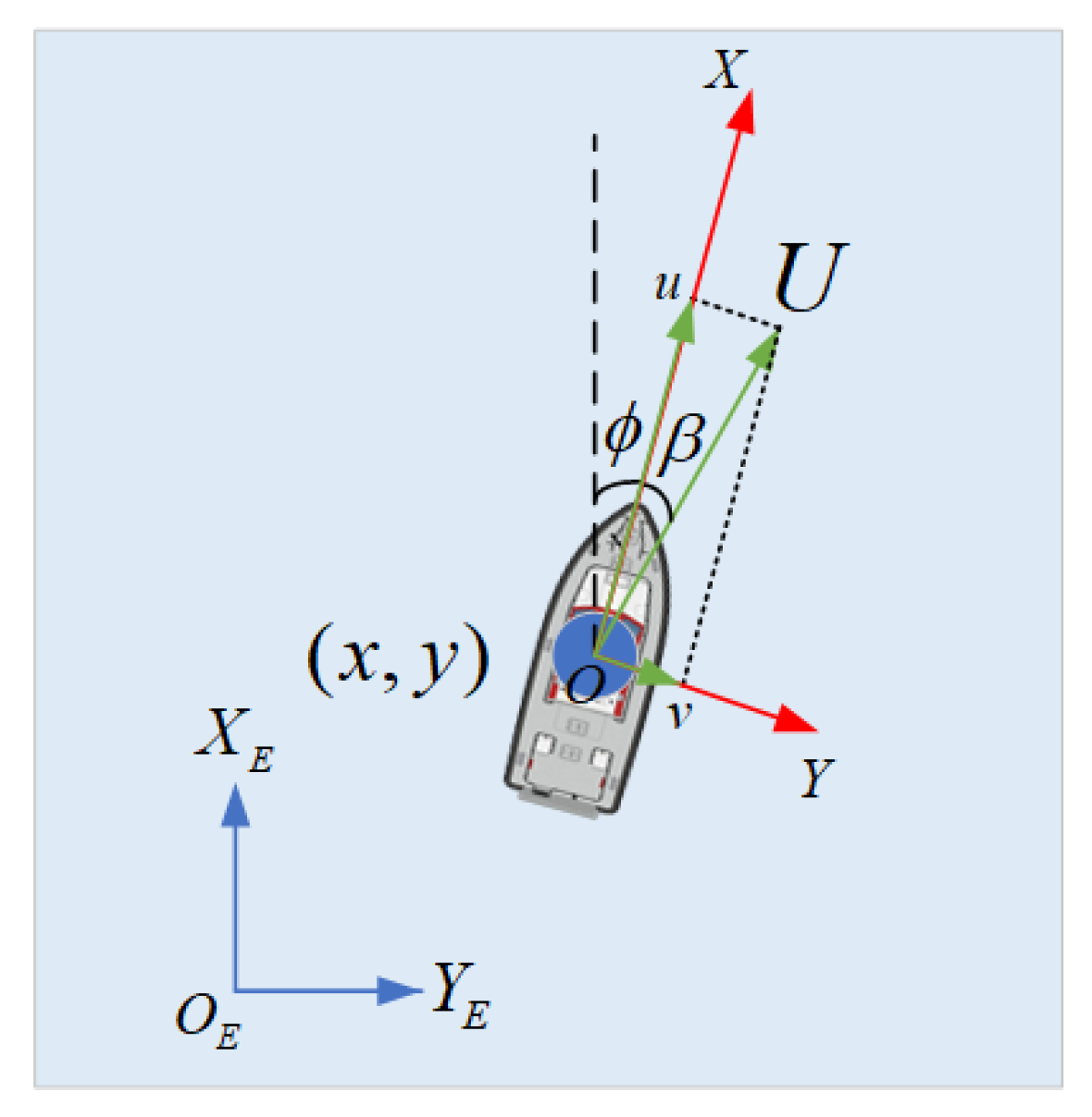
2.1. Description of an Underactuated USV’s Motion

To depict the motion of a USV, dynamics and kinematics equations are selected, and the control input is established to keep the dynamic positioning near the preset point. Since the dynamic positioning strategy of this paper is based on the USV’s PF control capability, the biggest task for us is to force the USV move along the reference paths given by the DP scheme.
Firstly, a fixed-time LOS is raised to obtain reliable control input, by which the desired signal named the reference heading angle is generated. Hence, the PF control problem of the USV is transformed into an angle tracking control problem. Therefore, the heading controller is designed for the heading angle tracking subsystem letter. Considering that the algorithm presented in this paper will be used in practical USV applications, a low-disturbance-sensitive and simple heading controller is indispensable, which will be discussed later. This section is devoted to describing the dynamics and kinematic equations of the USV, followed by the USV’s tracking error dynamics.
As shown in Figure 1, the USV’s kinematics equation is as follows, with η = x , y , ϕ T referring to the underactuated USV’s position and attitude in an inertial coordinate system O E X E Y E and v = u , v , r T representing the velocities in surge and sway, which are the yaw motions in the USV’s body-fixed coordinate system O X Y [32]:
η = J ( ϕ ) v ,
where
J ( ϕ ) = cos ϕ sin ϕ 0 sin ϕ cos ϕ 0 0 0 1
Ignoring the negative effects caused by uncertainties and disturbances, the dynamics equation is written as [32]:
M v + C ( v ) v + D ( v ) v = τ ,
in which τ = τ u , 0 , τ r T denotes the control input generated by controller, where τ u denotes the longitudinal thrust calculated by controller, and τ r is the yaw moment, which are used to regulate the USV’s surge, sway and yaw motions. Since underactuated USVs are not equipped with thrusters that provide lateral thrust, τ v = 0 . The inertia matrix M , coriolis and centripetal matrix C ( v ) , and damping matrix D ( v ) are defined as [29]:
M = d i a g ( m 11 , m 22 , m 33 ) , C ( v ) = 0 0 m 22 v 0 0 m 11 u m 22 v m 11 u 0 , D ( v ) = X u + u X u 2 0 0 0 Y v + v Y v 2 0 0 0 N r + r N r 2 .
 Remark 1: 
Though it is easier to deal with a dynamic positioning problem for a fully actuated USV using the methods in [33,34], those methods cannot be applied to underactuated USVs. However, compared to a fully-actuated one, an underactuated USV is more common in reality. This paper is intended to deal with the dynamic positioning problem for an underactuated USV.
 Assumption 1:
The velocities u , v , r and their derivations u , v , r of underactuated USVs are limited with a known constant.

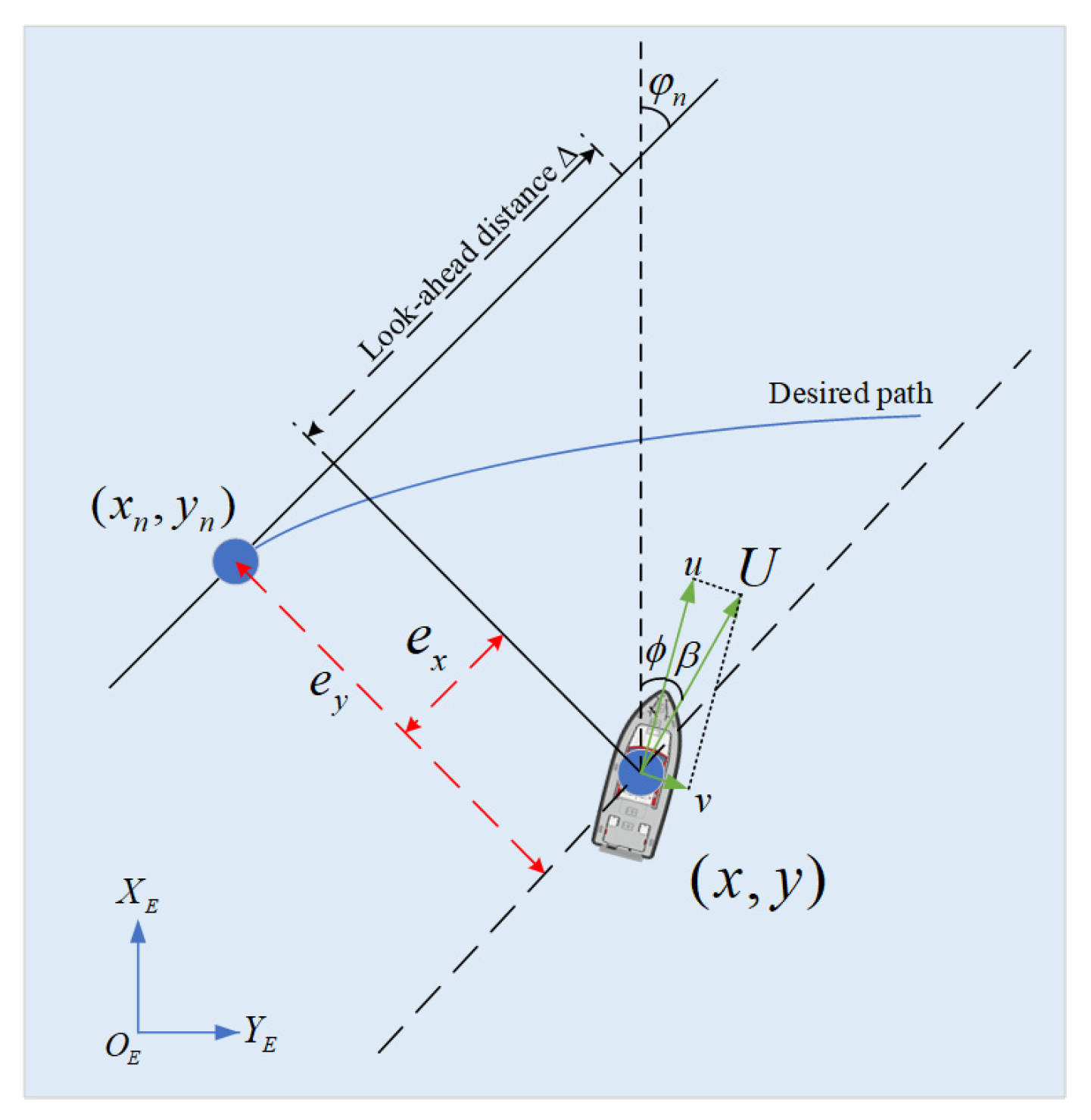
2.2. Tracking Error Dynamics of Underactuated USV

In this part, the tracking error dynamics based on the Serret–Frenet framework (SFF) are formed. We assume that any point used as a target ship is located on the desired path shown in Figure 2. The original point of the SFF is the target vessel itself, while the path’s tangent line and normal line are separately defined on its X-axis and Y-axis.
In Figure 2, φ n = arctan ( y n / x n ) is the path tangential angle. The along-tracking error e x and cross-tracking error e y can be calculated as:
e x = ( x x n ) cos φ n + ( y y n ) sin φ n ,
e y = ( x x n ) sin φ n + ( y y n ) cos φ n .
We define the target ship’s velocity along the desired path as v n = x n cos φ n + y n sin φ n .
Calculating the time-derivation of (3) and (4), we can derive the tracking error dynamics of an underactuated USV as:
e x = ( x x n ) cos φ n + ( y y n ) sin φ n + φ n e y = x cos φ n + y sin φ n v n + φ n e y
e y = ( x x n ) sin φ n + ( y y n ) cos φ n φ n e x = x sin φ n + y cos φ n φ n e x
We define U = u 2 + v 2 as the USV’s linear velocity, marking the sideslip angle as β = arctan ( v / u ) . If β varies slowly and to a small enough degree, it means β = 0 , sin β = 0 and cos β = 1 . We can then rewrite (5) and (6) as:
e x = U cos ( ϕ φ n ) U sin ( ϕ φ n ) β + φ n e y v n
e y = U sin ( ϕ φ n ) + U cos ( ϕ φ n ) φ n e x
The main objective of this manuscript is to establish a new dynamic positioning control structure for an underactuated USV. In order to make it clearer and simpler, the basic path-following ability of the USV itself is reapplied in the form of the DP control structure. Therefore, a novel guidance law is necessarily designed to calculate the desired signal. The heading control law is selected to force the motions of the USV. When the heading controller tracks the desired signal, the position tracking errors reduce to zero. Then, the dynamic positioning of the USV is realized.

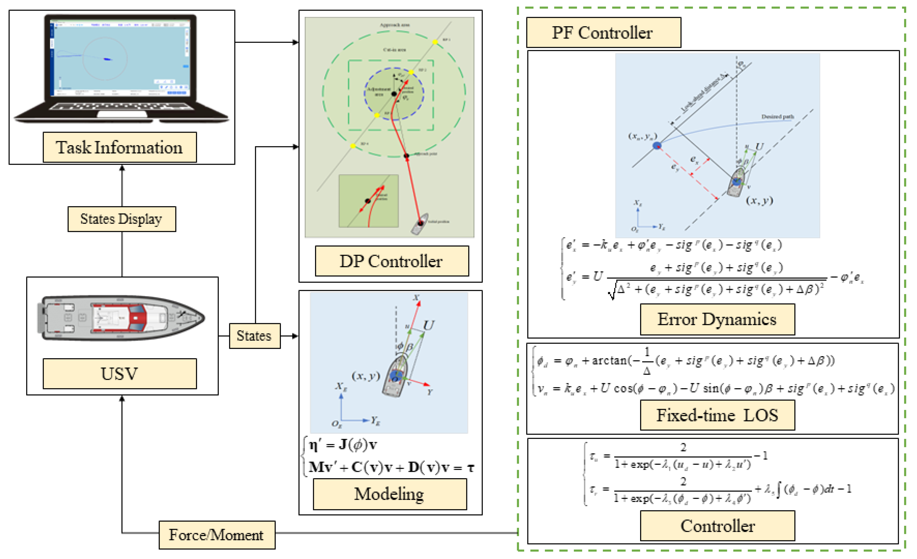
3. Dynamic Positioning Control Structure Design

We designed a dynamic positioning control structure using the fixed-time PF scheme. The DP scheme was first invented to show that the DP control problem transfers into a path following problem with a simple structure. Then, a fixed-time LOS is developed to generate the desired signal and thus assist the path following controller in forcing the position error to quickly reach zero.

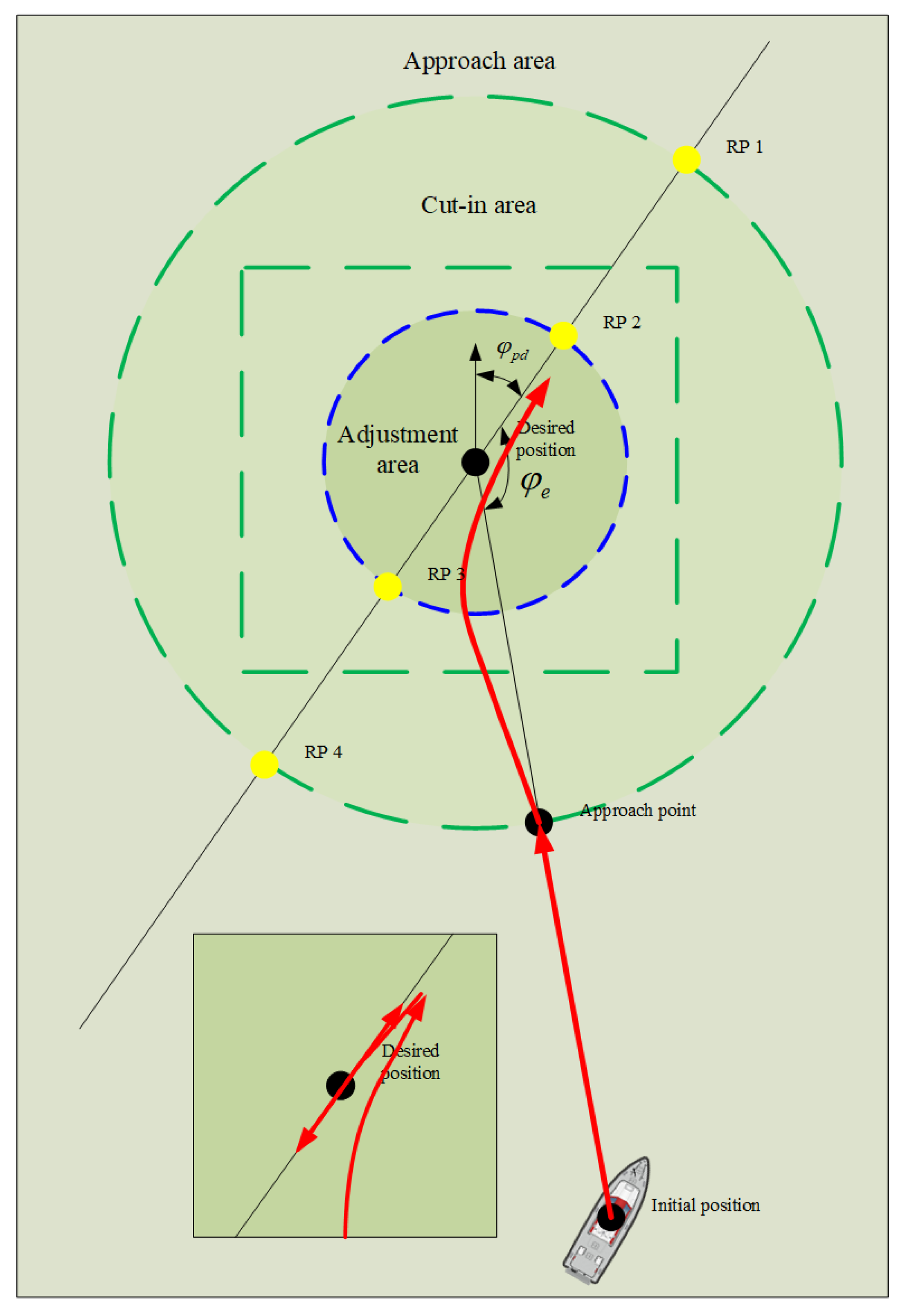
3.1. Design of Dynamic Positioning Scheme

For a fully actuated USV, it is easier to achieve dynamic positioning control by use of the thrusters providing transverse force, and there are many related research methods, but these methods are not suitable for an underactuated USV without transverse thrusters. When the USV performs dynamic positioning tasks, a very important consideration is that it needs to maintain a low speed when approaching the preset desired point, and it must constantly adjust the actuator to make sure that the desired positioning heading is tracked. Although the transverse force of an underactuated USV is always zero, when the USV has the capability of reversing, the dynamic positioning of an underactuated USV can be realized by designing a reasonable dynamic positioning strategy.
The USV dynamic positioning task area is divided into the approach area, the cut-in area and the adjustment area, as shown in Figure 3. Four reference points, R P 1 , R P 2 , R P 3 and R P 4 , are generated by the intersection between the segmentation circle of the three areas and the line through the desired position ( x d , y d ) point, the direction of which is the expected positioning course φ p d . The line formed by the desired position point and the USV’s initial position will bring us the approach point.
When the USV is located in the DP task area and receives the task command, the DP controller will first generate information on the desired speed u d , as follows:
u d = k 1 U max , A p p r o a c h a r e a k 2 U max , C u t i n a r e a k 3 U max , A d j u s t m e n t a r e a ,
where U max denotes the maximum speed of USV, and k i , i = 1 , 2 , 3 represent the parameters to be determined.
The azimuth information φ e π , π between the USV and the desired position point is determined according to the relationship between the USV heading angle ϕ and the desired positioning heading angle φ p d . φ e is used to judge the azimuth relationships between the USV and the desired position point, which are, respectively, right–front, left–front, right–back and left–back. The function of this judgment is mainly to generate the reference path required by the PF algorithm.
The reference path is shown in Table 1 below.
 Remark 2: 
According to the reference path generation method shown in the table above, the USV shown in Figure 3 will follow the red line and finally undertake a forward/backward motion near the desired position point. In reality, a USV fitted with a water-jet can achieve forward/backward motion by adjusting a device called the reverse bucket.

3.2. Fixed-Time LOS Design

Reference paths were generated by the DP scheme in Section 3.1; the next question is then how do we accurately follow these paths. Therefore, a fixed-time LOS will be proposed in Section 3.2.
Before giving the proof of the LOS guidance law and its stability, some lemmas are given.
Consider the following system:
x ( t ) = f ( t , x ( t ) ) , x ( 0 ) = x 0 . ,
where x n denotes the state vector, and f ( t , x ( t ) ) : + × n n is a nonlinear continuous function. Suppose that one of the equilibrium point of system (10) is its origin.
 Lemma 1 
([35,36]): Suppose x 1 , x 2 0 , 0 < σ 1 1 , σ 2 > 1 . Then, there is
x 1 σ 1 + x 2 σ 1 ( x 1 + x 2 ) σ 1 , x 1 σ 2 + x 2 σ 2 2 1 σ 2 ( x 1 + x 2 ) σ 2 .
 Lemma 2 
([37,38]): If function V ( x ) of system (10) satisfies
V ( x ) μ 1 V α ( x ) μ 2 V χ ( x )
in which χ > 1 , then a , b > 0 , 0 < α < 1 . Of course, V ( x ) is continuous, radial and unbounded. We can conclude that the system’s fixed-time stability is satisfied by setting the time limit as:
T T max : = 1 μ 1 ζ ( 1 α ) + 1 μ 2 ζ ( γ 1 ) , ζ ( 0 , 1 ) .
A USV’s desired heading angle is defined as:
ϕ d = φ n + arctan ( 1 Δ ( e y + s i g p ( e y ) + s i g q ( e y ) + Δ β ) ) ,
where Δ is he look-ahead distance. The designed parameters satisfy p > 1 , 0 < q < 1 .
We treat the target ship’s velocity v n as the virtual input:
v n = k u e x + U cos ( ϕ φ n ) U sin ( ϕ φ n ) β + s i g p ( e x ) + s i g q ( e x ) ,
where k u > 0 is another designed parameter.
 Theorem 1: 
The position tracking errors e x and e y in Figure 1 can be reduced to zero under the novel LOS law, shown as (11), within a fixed time.
 Proof
The Lyapunov function is taken into consideration:
V 1 = 1 2 ( e x 2 + e y 2 ) ,
From (11), we have
sin ( ϕ d φ n ) = e y + s i g p ( e y ) + s i g q ( e y ) + Δ β Δ 2 + ( e y + s i g p ( e y ) + s i g q ( e y ) + Δ β ) 2 ,
cos ( ϕ d φ n ) = Δ Δ 2 + ( e y + s i g p ( e y ) + s i g q ( e y ) + Δ β ) 2 .
Substituting (14) and (15) into (7) and (8), we have
e x = k u e x + φ n e y s i g p ( e x ) s i g q ( e x ) ,
e y = U e y + s i g p ( e y ) + s i g q ( e y ) Δ 2 + ( e y + s i g p ( e y ) + s i g q ( e y ) + Δ β ) 2 φ n e x .
The time-derivative of V 1 satisfies
V 1 = k u e x 2 γ e y 2 e x s i g p ( e x ) e x s i g q ( e x ) γ e y s i g p ( e y ) γ e y s i g q ( e y ) ,
in which γ = min ( U / Δ 2 + ( e y + s i g p ( e y ) + s i g q ( e y ) + Δ β ) 2 ) .
Due to s i g ρ ( e ) = e ρ s i g n ( e ) , (18) can be rewritten as:
V 1 k u e x 2 γ e y 2 k u e x 2 γ e y 2 e x e x p e x e x q γ e y e y p γ e y e y q k u e x 2 γ e y 2 ( e x 2 ) p + 1 2 ( e x 2 ) q + 1 2 γ ( e y 2 ) p + 1 2 γ ( e y 2 ) q + 1 2 .
According to Lemma 1, we have
V 1 ϖ V 2 δ ( e x 2 ) p + 1 2 δ ( e x 2 ) q + 1 2 δ ( e y 2 ) p + 1 2 δ ( e y 2 ) q + 1 2 ϖ V 2 δ V 2 p + 1 2 2 q + 1 2 δ V 2 q + 1 2 ,
where ϖ = min k u , γ > 0 , δ = min 1 , γ .
According to Lemma 2 and the form of (20), Theorem 1 can be proven, showing that the position errors e x and e y go down to zero within a fixed time,
t g T max : = 1 δ ζ ( p 1 2 ) + 1 2 1 q 2 δ ζ ( 1 q 2 ) , 0 < ζ < 1 .
 Remark 3: 
Here, a novel LOS is being proposed, which generates a reference signal and endows the tracking errors with fixed-time convergence. Under this guidance law, only a few parameters need to be adjusted, including Δ , k u , p , q , so the time required for parameter tuning will be greatly reduced when the guidance law is introduced into the practical application. The selection of the heading and speed control law should also follow the principle of fewer parameters and simple tuning.
 Remark 4: 
Although the non-quadratic Lyapunov functions shown in [39] lead to better performance, the quadratic Lyapunov function (13) is still considered in this paper because of the form of the kinematics Equation (1) and the dynamics Equation (2) of an underactuated USV. Regarding the robot’s mechanical and electrical dynamics, the positive–definite inertia matrix and inductance matrix are used to define the Lyapunov function candidates, which are always in form of a quadratic Lyapunov function.
The main purposes of this paper are declared above, in that the DP control scheme is designed to transfer the DP problem into a PF problem for an underactuated USV, and a novel fixed-time LOS guidance law is derived to transform this PF problem into a desired heading angle tracking problem. According to Remark 3, the incremental S-surface controller is selected for USV speed control, and the heading control of the USV is achieved using an integral S-surface controller. Their forms are shown as:
τ u = 2 1 + exp ( λ 1 ( u d u ) + λ 2 u ) 1 τ r = 2 1 + exp ( λ 3 ( ϕ d ϕ ) + λ 4 ϕ ) + λ 5 ( ϕ d ϕ ) d t 1 ,
where λ i , i = 1 , 2 , 3 , 4 , 5 are parameter-adjusted letters. Because these two controllers have been widely used in practical engineering control, detailed proof of the stability of (21) is omitted here to save space. The block of the proposed approach shown in Figure 4 is given to clarify the design procedure and the controller’s structure to allow better comprehension.

4. Analysis of Numerical Simulation and Practical Experiment

The proposed DP control method will be verified by both numerical simulations and practical experiments. Because the method only involves the following of a straight path, curved paths will not be tracked and verified in the simulations and experiments. At the same time, due to the constraints of experiment time and other factors, no comparative experiment was carried out here, and only its feasibility and robustness have been verified.

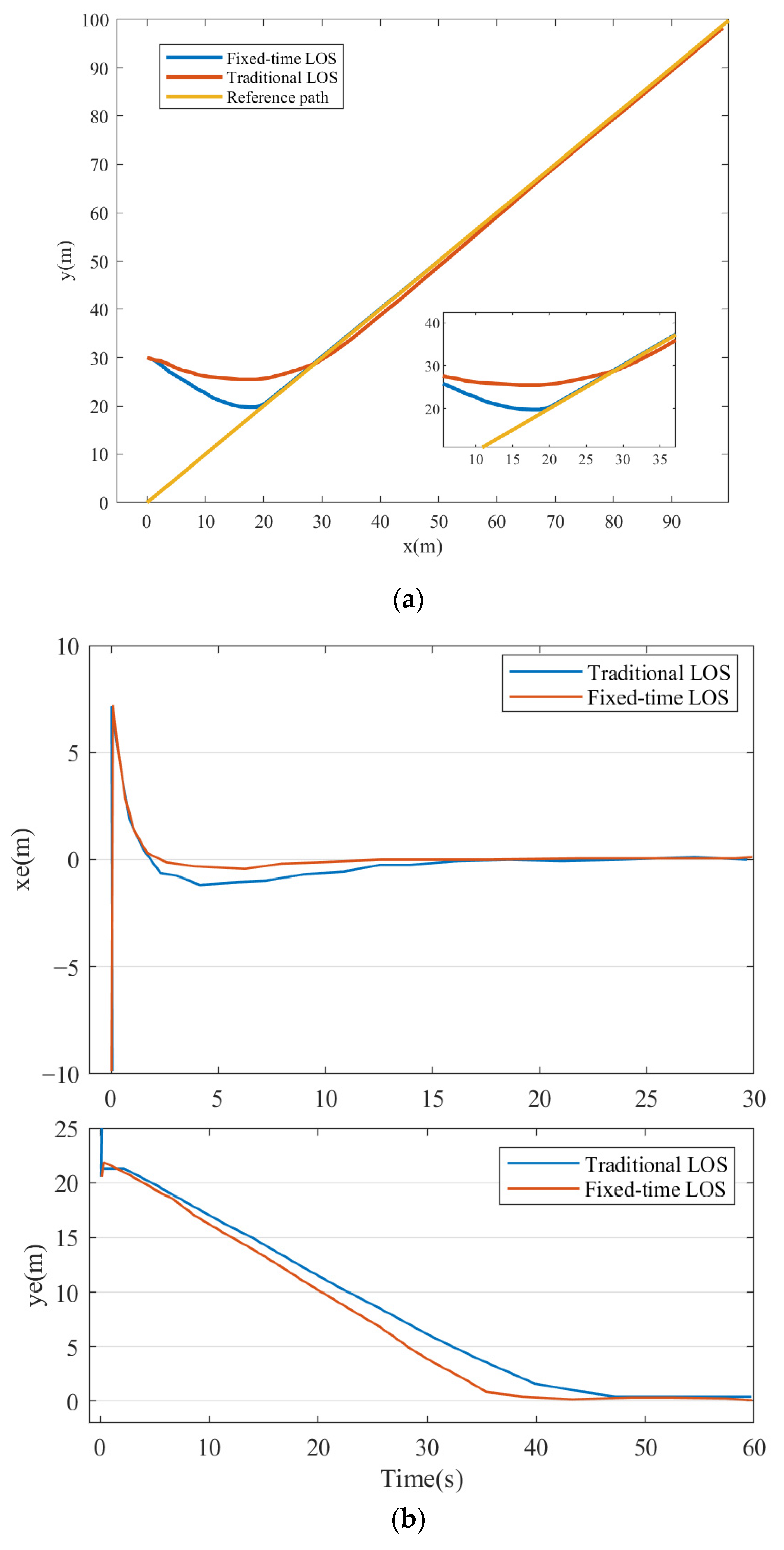
4.1. Numerical Simulation and Its Analysis

In this section, the USV’s fixed-time PF control capabilities and dynamic positioning control capabilities will be demonstrated. Before the numerical simulations are undertaken, the relevant parameters of the USV must be given, as in Table 2:
Case 1 demonstrates the straight path-following ability of a USV by using the designed fixed-time LOS guidance law under time-varying disturbances. At the same time, the traditional LOS method is used to design comparative experiments. x = y = ϑ describes the straight path that is required, and the desired velocity u d = 1 . The disturbances are selected as: τ d = 3 sin ( 0.1 π t ( π / 5 ) ) , cos ( 0.1 π t + ( π / 6 ) ) , 3 cos ( 0.2 π t + ( π / 3 ) ) T . The initial positions of the USV are set as x ( 0 ) y ( 0 ) ϕ ( 0 ) T = 0 m 30 m 0 r a d T and the initial velocities are 0. The designed parameters are given in Table 3.
The straight path-following performances are shown in Figure 5a. Compared to the traditional LOS, the proposed fixed-time LOS achieves a better performance in two aspects: following the preset path precisely and reaching the preset path quickly.
More intuitively, although the tracking errors can both reach zero under these two guidance laws, it can be seen from the along-tracking error x e and cross-tracking error y e curves shown in Figure 5b that the newly proposed one achieves better convergence. The results show that when the fixed-time LOS is adopted, the positioning error approaches zero about 10 s faster. This results in a controller with a fixed time LOS guidance law that can enable the USV to reach the preset path much faster. Generally speaking, the USV’s trajectory under fixed-time LOS is closer to the preset path shown in Figure 5a.
In case 2, the dynamic positioning control ability of the underactuated USV is verified. We have given the desired position point and expected positioning heading angle as follows: x d y d T = 119.6209489 ( l o n ) 39.89857318 ( l a t ) T , φ p d = 100 ° . The values of the DP controller’s parameters are given in Table 4.
The performance of the DP following the proposed method is displayed in Figure 6, Figure 7 and Figure 8.
It can be seen from Figure 6 that the USV has a dynamic positioning control capability. Further, we can conclude from Figure 7 that the position error is less than 5 m when using the proposed fixed-time PF-based DP controller. As can be seen from Figure 8, regular heading adjustment will be carried out when the USV approaches the desired position point, because when it approaches that point, the speed of the USV will drop to a relatively low level. At this time, due to the influence of marine environmental factors, the position will be offset, so it is necessary to constantly adjust the heading and track. Figure 6 shows that the USV undertakes regular forward/backward motions in a small range near the desired position point to resist the disturbances brought by environmental factors. Although the oscillation amplitude of the error in position measurements at about 6 m still yields a large deviation compared with the length of a USV, the position tolerance error is often set as 20 m according to the actual task requirements. If the sea conditions are poor, the value will be set higher. Therefore, the new fixed-time PF-based DP control strategy designed in this paper can be applied in practice.

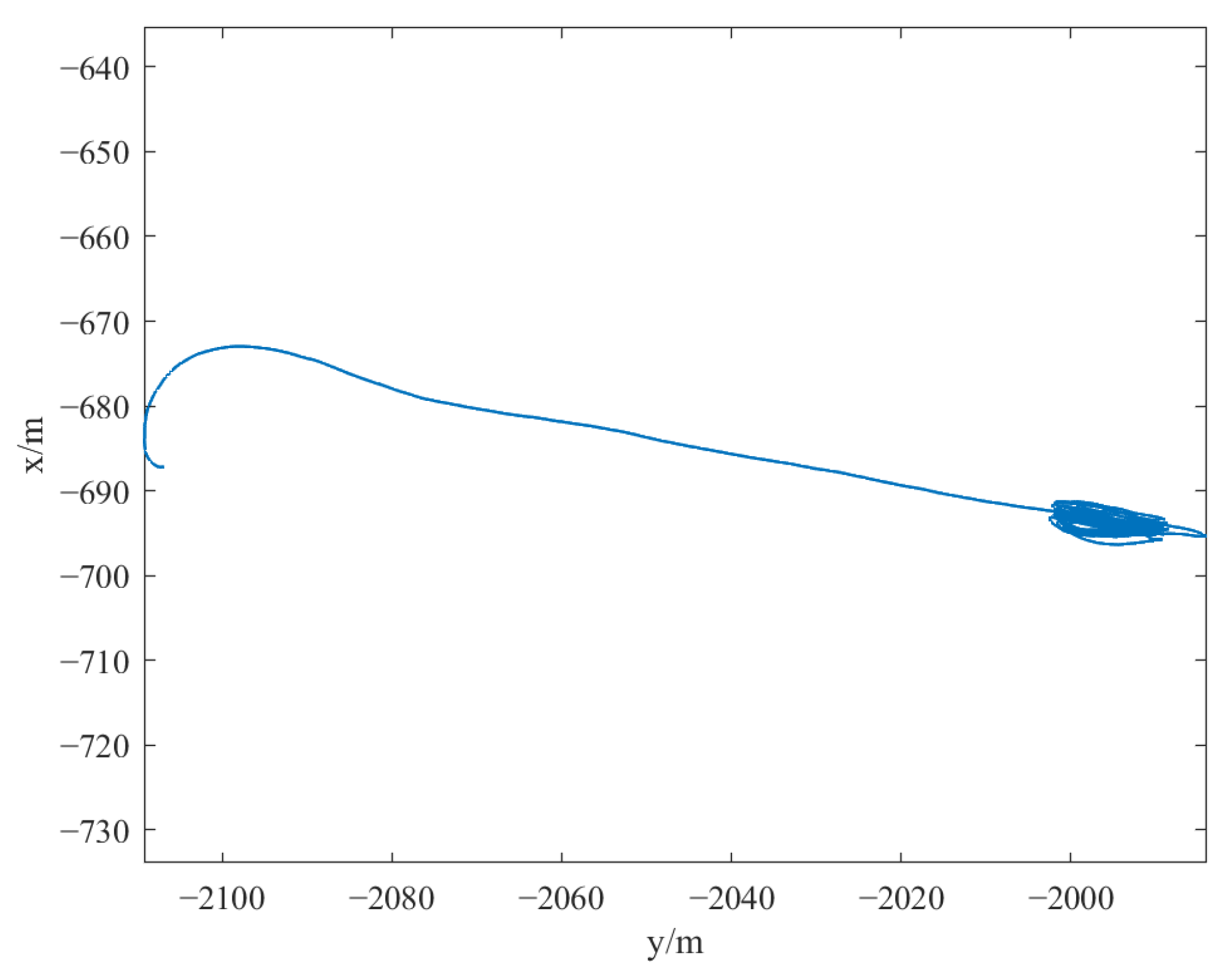
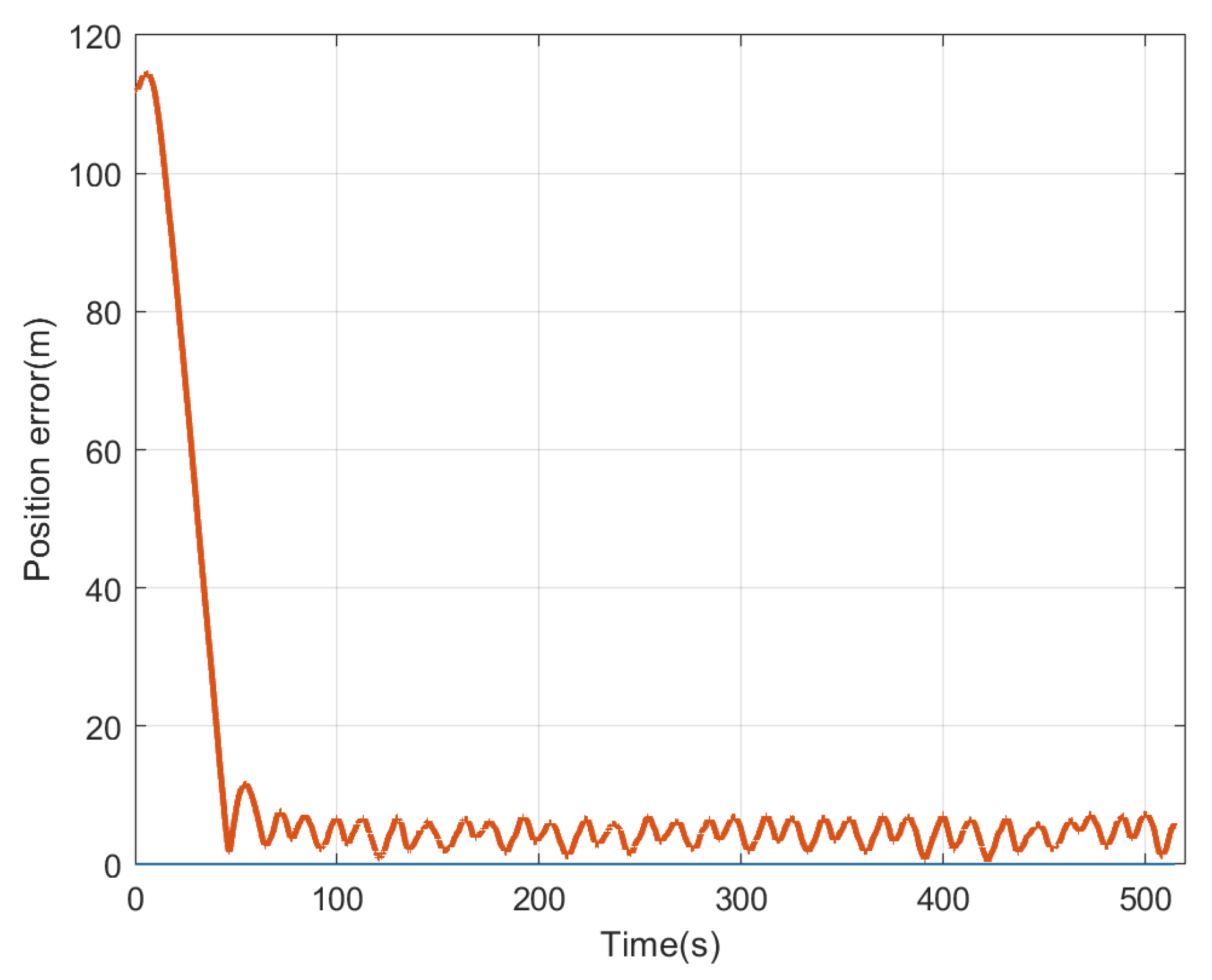
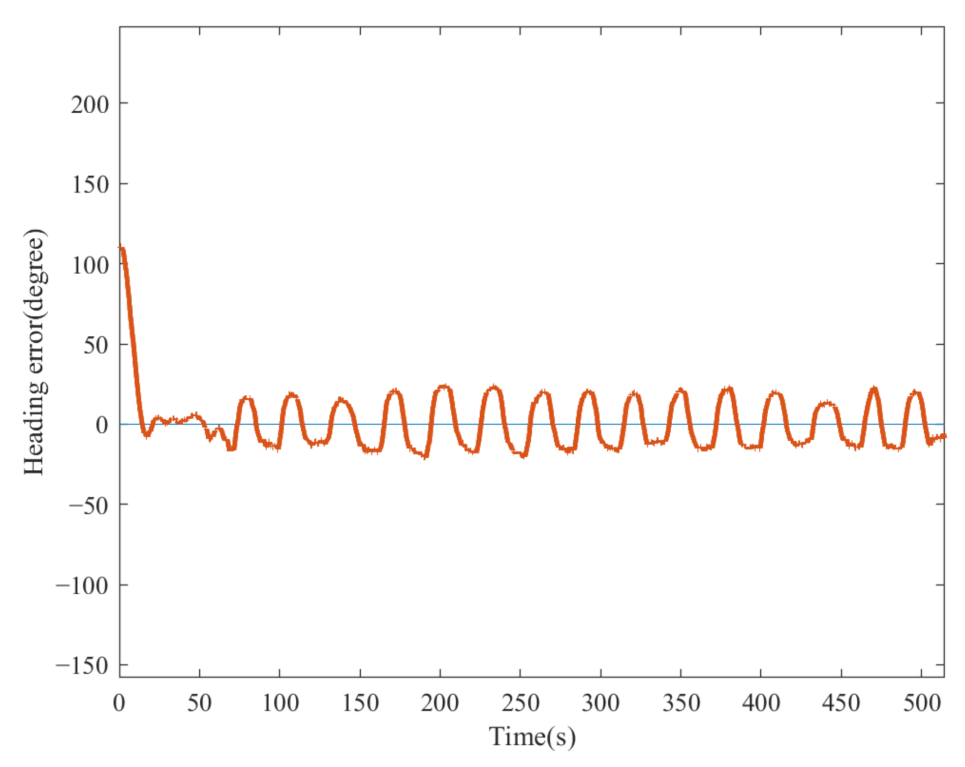
4.2. Practical Experiment and Its Analysis

A practical experiment has been carried out on the seashore of Qinhuangdao. The USV and its land monitoring station here communicate through a wireless communication system. The desired position point and expected positioning heading angle are as follows: x d y d T = 119.6209489 ( l o n ) 39.89857318 ( l a t ) T , φ p d = 100 ° . The practical positioning performance of the method proposed in this paper is displayed in Figure 9, Figure 10 and Figure 11.
It can be seen from Figure 9 that when adjusting design parameters appropriately, the USV can attain a dynamic positioning control capacity under external disturbances. However, affected by the influence of marine environmental factors that cannot be modeled, Figure 10 shows us that the position error varies between 5 and 8 m, and its amplitude becomes unstable when compared to Figure 6. At the same time, the oscillation of the heading error also becomes severe.

5. Conclusions and Future Work

A dynamic positioning control method for an underactuated USV based on its own PF capability is presented in this paper. Because exploration and monitoring tasks often require the USV be located at a certain point and moving in a fixed direction, developing a DP with minimal computational cost and faster convergence on the premise of ensuring the simplicity and easy implementation of the algorithm is one of the main obstacles in the completion of a USV offshore missions. In order to solve this problem, the algorithm simplifies the USV’s DP problem into two parts—path generation and path following—and uses its own PF control algorithm to follow the paths generated by the DP controller. In addition, the algorithm also includes a PF control module based on fixed-time LOS, which improves the state convergence speed of the USV under the influence of the algorithm. Both numerical simulations and practical experiments prove that, benefiting from the proposed method, DP control can be realized with good robustness.
In future research, refining the dynamic positioning control strategy to generate smoother reference paths and meet the global fixed-time convergence requirements will become the focus.

Author Contributions

Conceptualization, S.Z., Y.S., J.Z., Y.T. and G.Y.; methodology, S.Z. and Y.T.; software, S.Z.; validation, S.Z. and G.Y.; formal analysis, S.Z.; investigation, S.Z., J.Z. and Y.S; resources, S.Z.; data curation, S.Z. and Y.T.; writing—original draft preparation, S.Z.; writing—review and editing, S.Z., G.Y. and J.Z.; visualization, S.Z.; supervision, Y.S.; project administration, J.Z.; funding acquisition, J.Z. All authors have read and agreed to the published version of the manuscript.

Funding

This research was funded by the National Natural Science Foundation of China (Grant no.’s 52071100).

Institutional Review Board Statement

Not applicable.

Informed Consent Statement

Not applicable.

Data Availability Statement

The data presented in this study are available on request from the corresponding author. Data are unavailable due to privacy restrictions.

Conflicts of Interest

The authors declare no conflicts of interest.

References

  1. Huang, B.; Song, S.; Zhu, C. Finite-time distributed formation control for multiple unmanned surface vehicles with input saturation. Ocean Eng. 2021, 233, 109158. [Google Scholar] [CrossRef]
  2. Huang, B.; Zhang, S.; He, Y.; Wang, B.; Deng, Z. Finite-time anti-saturation control for Euler–Lagrange systems with actuator failures. ISA Trans. 2022, 124, 468–477. [Google Scholar] [CrossRef] [PubMed]
  3. Zhou, B.; Huang, B. Two-layer leader-follower optimal affine formation maneuver control for networked unmanned surface vessels with input saturations. Int. J. Robust. Nonlinear Control 2024, 34, 3631–3655. [Google Scholar] [CrossRef]
  4. Mu, D.; Wang, G.; Fan, Y. Path Following Control Strategy for Underactuated Unmanned Surface Vehicle Subject to Multiple Constraints. IEEJ Trans. Electr. Electron. Eng. 2022, 17, 229–241. [Google Scholar] [CrossRef]
  5. Huang, B.; Zhou, B.; Zhang, S. Adaptive prescribed performance tracking control for underactuated autonomous underwater vehicles with input quantization. Ocean Eng. 2021, 221, 108549. [Google Scholar] [CrossRef]
  6. Fu, M.; Zhang, G.; Xu, Y. Discrete-time adaptive predictive sliding mode trajectory tracking control for dynamic positioning ship with input magnitude and rate saturations. Ocean Eng. 2023, 269, 113528. [Google Scholar] [CrossRef]
  7. Zhou, B.; Huang, B.; Su, Y.; Zhu, C. Interleaved periodic event-triggered communications based distributed formation control for cooperative unmanned surface vessels. IEEE Trans. Neural Netw. Learn. Syst. 2024. early access. [Google Scholar] [CrossRef]
  8. Peng, H.; Huang, B.; Miao, J.; Zhu, C.; Zhuang, J. Distributed Finite-time Bearing-based Formation Control for Underactuated Surface Vessels with Levant Differentiator. ISA Trans. 2024, in press. [Google Scholar] [CrossRef] [PubMed]
  9. Wang, Z.; Li, Y.; Ma, C.; Yan, X.; Jiang, D. Path-following optimal control of autonomous underwater vehicle based on deep reinforcement learning. Ocean Eng. 2023, 268, 113407. [Google Scholar] [CrossRef]
  10. Hu, X.; Du, J.; Sun, Y. Robust adaptive control for dynamic positioning of ships. IEEE J. Ocean. Eng. 2017, 42, 826–835. [Google Scholar] [CrossRef]
  11. Sarda, E.I.; Bertaska, I.R.; Qu, A.; Von Ellenrieder, K.D. Development of a USV station-keeping controller. In Proceedings of the OCEANS 2015, Genova, Italy, 18–21 May 2015. [Google Scholar] [CrossRef]
  12. Sarda, E.I.; Qu, H.; Qu, A.; Von Ellenrieder, K.D. Station-keeping control of an unmanned surface vehicle exposed to current and wind disturbances. Ocean Eng. 2016, 127, 305–324. [Google Scholar] [CrossRef]
  13. Vu, M.T.; Le Thanh, H.N.; Huynh, T.T.; Thang, Q.; Duc, T.; Hoang, Q.D.; Le, T.H. Station-Keeping Control of a Hovering Over-Actuated Autonomous Underwater Vehicle Under Ocean Current Effects and Model Uncertainties in Horizontal Plane. IEEE Access 2021, 9, 6855–6867. [Google Scholar] [CrossRef]
  14. Chellapurath, M.; Walker, K.L.; Donato, E.; Picardi, G.; Stefanni, S.; Laschi, C.; Giorgio-Serchi, F.; Calisti, M. Analysis of station keeping performance of an underwater legged robot. IEEE/ASME Trans. Mechatron. 2021, 27, 3730–3741. [Google Scholar] [CrossRef]
  15. Aguiar, A.P.; Pascoal, A.M. Dynamic positioning and waypoint tracking of underactuated AUVs in the presence of ocean currents. Int. J. Control 2007, 80, 1092–1108. [Google Scholar] [CrossRef]
  16. Dong, Z.; Wan, L.; Li, Y.M. Point stabilization for an underactuated AUV in the presence of ocean currents. Int. J. Adv. Robot. Syst. 2015, 12, 1–14. [Google Scholar] [CrossRef]
  17. Hu, X.; Du, J. Robust nonlinear control design for dynamic positioning of marine vessels with thruster system dynamics. Nonlinear Dyn. 2018, 94, 365–376. [Google Scholar] [CrossRef]
  18. Xie, W.; Ma, B.; Fernando, T.; Iu, H.H. A simple robust control for global asymptotic position stabilization of underactuated surface vessels. Int. J. Robust Nonlinear Control 2017, 27, 5028–5043. [Google Scholar] [CrossRef]
  19. Li, H.; Yan, W. Model predictive stabilization of constrained underactuated autonomous underwater vehicles with guaranteed feasibility and stability. IEEE/ASME Trans. Mechatron. 2017, 22, 1185–1194. [Google Scholar] [CrossRef]
  20. Guo, G.; Zhang, P. Asymptotic stabilization of USVs with actuator dead-zones and yaw constraints based on fixed-time disturbance observer. IEEE Trans. Veh. Technol. 2020, 69, 302–316. [Google Scholar] [CrossRef]
  21. Fossen, T.I.; Breivik, M.; Skjetne, R. Line-of-sight path following of underactuated marine craft. IFAC Proc. Vol. 2003, 36, 211–216. [Google Scholar] [CrossRef]
  22. Fossen, T.I.; Pettersen, K.Y. On uniform semiglobal exponential stability (USGES) of proportional line-of-sight guidance laws. Automatica 2014, 50, 2912–2917. [Google Scholar] [CrossRef]
  23. Xiao, Y.; Shao, H.; Wang, J.; Yan, S.; Liu, B. Bayesian Variational Transformer: A Generalizable Model for Rotating Machinery Fault Diagnosis. Mech. Syst. Signal Process. 2024, 207, 110936. [Google Scholar] [CrossRef]
  24. Luo, J.; Shao, H.; Lin, J.; Liu, B. Meta-learning with elastic prototypical network for fault transfer diagnosis of bearings under unstable speeds. Reliab. Eng. Syst. Saf. 2024, 245, 110001. [Google Scholar] [CrossRef]
  25. Haidong, S.; Xiangdong, Z.; Jian, L.; Bin, L. Few-shot cross-domain fault diagnosis of bearing driven by Task-supervised ANIL. IEEE Internet Things J. 2024. [Google Scholar] [CrossRef]
  26. Wan, L.; Su, Y.; Zhang, H.; Shi, B.; AbouOmar, M.S. An improved integral light-of-sight guidance law for path following of unmanned surface vehicles. Ocean Eng. 2020, 205, 107302. [Google Scholar] [CrossRef]
  27. Dai, S.; Wu, Z.; Wang, J.; Tan, M.; Yu, J. Barrier-based adaptive line-of-sight 3-D path-following system for a multi-joint robotic fish with sideslip compensation. IEEE Trans. Cybern. 2022, 53, 4204–4217. [Google Scholar] [CrossRef] [PubMed]
  28. Fan, Y.; Qiu, B.; Liu, L.; Yang, Y. Global fixed-time trajectory tracking control of underactuated USV based on fixed-time extended state observer. ISA Trans. 2023, 132, 267–277. [Google Scholar] [CrossRef] [PubMed]
  29. Wang, S.D.; Sun, M.W.; Liu, J. Fixed-Time Predictor-Based Path Following Control of Unmanned. Surf. Veh. Control Theory Appl. 2022, 39, 1845–1853. [Google Scholar]
  30. Nie, J.; Wang, H.; Lu, X.; Lin, X.; Sheng, C.; Zhang, Z.; Song, S. Finite-time output feedback path following control of underactuated MSV based on FTESO. Ocean Eng. 2021, 224, 108660. [Google Scholar] [CrossRef]
  31. Qin, H.; Li, C.; Sun, Y.; Li, X.; Du, Y.; Deng, Z. Finite-time trajectory tracking control of unmanned surface vessel with error constraints and input saturations. J. Frankl. Inst. 2020, 357, 11472–11495. [Google Scholar] [CrossRef]
  32. Fossen, T.I.; Pettersen, K.Y.; Galeazzi, R. Line-of-sight path following for dubins paths with adaptive sideslip compensation of drift forces. IEEE Trans. Control Syst. Technol. 2014, 23, 820–827. [Google Scholar] [CrossRef]
  33. Li, J.; Xiang, X.; Dong, D.; Yang, S. Saturated-command-deviation based finite-time adaptive control for dynamic positioning of USV with prescribed performance. Ocean Eng. 2022, 266, 112941. [Google Scholar] [CrossRef]
  34. Huang, H.; Sharma, S.; Zhuang, Y.; Xu, D. Dynamic positioning of an uninhabited surface vehicle using state-dependent Riccati equation and pseudospectral method. Ocean Eng. 2017, 133, 215–223. [Google Scholar] [CrossRef]
  35. Liu, J.; Zhang, Y.; Sun, C.; Yu, Y. Fixed-time consensus of multi-agent systems with input delay and uncertain disturbances via event-triggered control. Inf. Sci. 2019, 480, 261–272. [Google Scholar] [CrossRef]
  36. Polyakov, A. Nonlinear feedback design for fixed-time stabilization of linear control systems. IEEE Trans. Autom. Control 2011, 57, 2106–2110. [Google Scholar] [CrossRef]
  37. Liu, J.; Zhang, Y.; Yu, Y.; Liu, H.; Sun, C. A Zeno-free self-triggered approach to practical fixed-time consensus tracking with input delay. IEEE Trans. Syst. Man Cybern. Syst. 2021, 52, 3126–3136. [Google Scholar] [CrossRef]
  38. Liu, J.; Ran, G.; Wu, Y.; Xue, L.; Sun, C. Dynamic event-triggered practical fixed-time consensus for nonlinear multiagent systems. IEEE Trans. Circuits Syst. II Express Briefs 2021, 69, 2156–2160. [Google Scholar] [CrossRef]
  39. Hosseinzadeh, M.; Yazdanpanah, M.J. Performance enhanced model reference adaptive control through switching non-quadratic Lyapunov functions. Syst. Control Lett. 2015, 76, 47–55. [Google Scholar] [CrossRef]
Figure 1. Illustration of two coordinate systems.
Jmse 12 00551 g001
Figure 2. Guidance geometry of LOS.
Jmse 12 00551 g002
Figure 3. Illustration of DP control scheme.
Jmse 12 00551 g003
Figure 4. PF-based DP controller for an underactuated USV.
Jmse 12 00551 g004
Figure 5. (a) The PF performance. (b) The PF performance.
Jmse 12 00551 g005
Figure 6. Dynamic positioning performance in the numerical simulation.
Jmse 12 00551 g006
Figure 7. Position error of the numerical simulation.
Jmse 12 00551 g007
Figure 8. Heading error of the numerical simulation.
Jmse 12 00551 g008
Figure 9. The practical performance of the DP controller.
Jmse 12 00551 g009
Figure 10. Position error of the practical experiment.
Jmse 12 00551 g010
Figure 11. Heading error of the practical experiment.
Jmse 12 00551 g011
Table 1. Reference path waypoints generation.
CaseWaypoint 1Waypoint 2Forward/BackwardBasis
1————Forward A d j u s t m e n t a r e a
2 R P 4 R P 3 Backward C u t i n a r e a π / 2 φ e < π / 2
3 R P 2 R P 1 Forward C u t i n a r e a φ e π , π / 2   o r   φ e π / 2 , π
4USV’s positionDesired positionForward A p p r o a c h a r e a
Table 2. The underactuated USV’s dynamic parameters.
Mark m 11 m 22 m 33 X u X u 2 Y v Y v 2 N r N r 2
Value215265807010010020050100
Unit kg kg kg m 2 kg / s kg / m kg / s kg / m kg m 2 / s kg m 2
Table 3. Designed parameters of path-following controller.
SectionSymbolValue
Fixed-time LOS guidance k u 6.0
p 1.5
q 0.4
Δ 30.0
Speed controller λ 1 7.5
λ 2 3.5
Heading controller λ 3 12.0
λ 4 3.0
λ 5 6.5
Table 4. Design parameters of the DP controller.
SectionSymbolValue
DP controller k 1 , k 2 , k 3 , U max 0.2 , 0.1 , 0.05 , 5
Disclaimer/Publisher’s Note: The statements, opinions and data contained in all publications are solely those of the individual author(s) and contributor(s) and not of MDPI and/or the editor(s). MDPI and/or the editor(s) disclaim responsibility for any injury to people or property resulting from any ideas, methods, instructions or products referred to in the content.

