Article

uw-WiFi: Small-Scale Data Collection Network-Based Underwater Internet of Things

1
College of Computer Science and Technology, Jilin University, Changchun 130012, China
2
Shenzhen Institute for Advanced Study, UESTC, Shenzhen 518110, China
3
Smart Ocean Technology Co., Ltd., Shenzhen 518110, China
*
Author to whom correspondence should be addressed.
J. Mar. Sci. Eng. 2024, 12(3), 481; https://doi.org/10.3390/jmse12030481
Submission received: 30 January 2024 / Revised: 27 February 2024 / Accepted: 11 March 2024 / Published: 13 March 2024
(This article belongs to the Special Issue Underwater Wireless Communications: Recent Advances and Challenges)

Abstract

:
The establishment of the Underwater Internet of Things (UIoT) and the realization of interconnection between heterogeneous underwater intelligent devices are urgent global challenges. Underwater acoustic networking is the most suitable technology to achieve UIoT for medium to long ranges. This paper presents an underwater Wi-Fi network, called uw-WiFi, that utilizes a master–slave mode architecture. uw-WiFi is dedicated to solving the problem of underwater acoustic networking with limited coverage range and number of nodes. To ensure the reliability of different types of data in the network, a reliable segmentation transmission protocol based on data type is designed. Additionally, on-demand scheduling based on the reservation MAC protocol is developed to solve the channel resource sharing problem. The uw-WiFi system has undergone shallow sea tests, and the experimental results demonstrate that the uw-WiFi network is capable of achieving a network throughput of 500 bps or higher, indicating superior network performance.

1. Introduction

In-depth exploration and study of oceans is of great importance to human development [1,2,3,4]. The concept of the Underwater Internet of Things (UIoT), which is defined as a world-wide network of smart interconnected underwater objects, has continued to gain in popularity since the 2010s [5]. The establishment of the UIoT and the realization of interconnection, information sharing, and cooperative operation between heterogeneous underwater intelligent devices are urgent global challenges. Compared with other underwater communication methods, underwater acoustic communication (UAC) is currently recognized as a low-cost communication mode suitable for medium to long ranges [6,7]. The gradual maturity of UAC technology has laid the foundation for the development of underwater acoustic networking technology, which is a crucial component of ocean information systems that enables the interconnection of underwater intelligent devices. Underwater acoustic networking is the most suitable technology to achieve UIoT for medium to long ranges.
Underwater acoustic networking technology has attracted a great deal of interest over the last few decades. Underwater acoustic networks (UANs) are a series of distributed systems that use UAC technology to achieve interconnection and information sharing among multiple heterogeneous intelligent platforms by solving the problems of channel resource sharing, information routing planning, and reliable data transmission. However, the disadvantages of UAC, such as long propagation delays, limited bandwidth, signal fading, asymmetric links, high error probability, and extended multipath propagation [8,9], are always the key factors limiting the performance and application development of UANs.
One of the most important functions of the UANs is to solve the problem of heterogeneous nodes networking in underwater environments with limited coverage range and number of nodes, to eventually achieve the goals of multidimensional environmental detection and data collection back to the shore-based center. We usually refer to networks with the above characteristics as small-scale data collection-based UANs. The fundamentals of this type of UAN are that the nodes collect and pre-process the detected data, then send them to a preset sink node using UAC. Then, the sink node forwards the data to the land-based network [10]. However, the nature of UAC dictates that it is challenging and arduous to perform efficient data collection in the UANs [11].
  • Establish the network communication link quickly. One of the key challenges that this type of underwater acoustic network needs to address is the need for rapid exploration and monitoring of a specific area in real-world applications, as well as the quick transmission of results to an onshore platform for other task planning purposes. In the target marine area, the deployment positions of network nodes are relatively random, and it is not necessary to specify a specific deployment location for each node. Therefore, after deploying the corresponding network nodes in this area, it is necessary to quickly establish network connections between the onshore platform and multiple underwater network nodes, allowing the onshore platform to quickly understand the underwater environment and situational information based on the sensor data reported by the network nodes.
  • Address the dynamically changing network topology. In this type of underwater acoustic network, there may be issues with network topology changes due to the addition or departure of nodes for various reasons. For example, underwater network nodes are typically powered by batteries, and when the battery is depleted, the node leaves the network and rejoins after being redeployed. Additionally, to meet the requirements of multidimensional and flexible data collection, a specific number of mobile nodes are deployed based on the actual situation to perform the corresponding data collection tasks. These mobile nodes may leave the communication range of the data aggregation node to collect data and then return for data reporting. In such cases, the unpredictable changes in the number of nodes and the topology of the underwater network pose high demands on the scalability and robustness of the network.
  • Configure network operational parameters appropriately. The underwater acoustic channel is significantly affected by the underwater environment. For example, the non-autonomous movement of network nodes caused by factors such as ocean currents, tides, and waves results in severe Doppler effects. This phenomenon degrades carrier recovery and symbol synchronization, leading to data loss and communication failures. Additionally, the propagation speed of sound signals underwater is influenced by temperature, pressure, and salinity. This ultimately manifests as a sound velocity profile, where sound signals have different propagation speeds at different depths. Sound signals also exhibit characteristics of bending towards regions with lower sound velocity during propagation. In shallow water environments, phenomena like the “afternoon effect” can easily occur, causing the communication link to be unstable and experiencing temporal and spatial uncertainties. Therefore, during network operation, it is necessary to understand the current operating environment and configure the network node’s operational parameters accordingly in real-time.
However, due to the unique nature of the hydroacoustic channel, terrestrial networking protocols do not work well in the underwater environment [8,12]. Therefore, compared to terrestrial wireless networks, the underwater acoustic network based on underwater acoustic communication is a highly unreliable networking system. Its unreliability mainly stems from low communication rates, low effective data throughput, high propagation delays, and communication conditions that are easily affected by the environment.
In this paper, we propose a UAN with a Wi-Fi network architecture called uw-WiFi. It mainly solves the problem of fast networking of heterogeneous nodes in small-scale UANs. The uw-WiFi is a UAN system with master–slave mode architecture, which has strong robustness and flexibility. The master node, acting as the gateway node, is responsible for connecting the underwater network to the land-based network and completing the cross-domain data transfer. The slave node, acting as the terminal node, is distributed within the coverage area of the gateway node. Different types of terminal nodes will be deployed in designated underwater areas according to different tasks. There is no negative impact on other nodes in the network caused by terminal nodes that join or leave the network. A scheduling-based medium access control (MAC) protocol, called SDDA, was designed to manage the shared communication channel. This paper also solves the problem of reliability of different types of data in the network by designing a reliable segmentation transmission protocol. In addition to this, we provide an in-depth analysis of the scalability of the network in terms of both single and multiple uw-WiFi networks, respectively.
As a case study, a uw-WiFi network with six nodes has been implemented and deployed in the shallow sea environment. The main tasks of this network are collecting data from various underwater sensors and controlling network nodes. The network consists of a base station node, four fixed terminal nodes, and one mobile terminal node. We have implemented protocols in each layer for the targeted network. The uw-WiFi network operated unattended for up to 50 days without error after deployment. The results of experiments in a real environment show that the uw-WiFi network not only can be stably applied in the real marine environment and achieve pre-set network functions, but also has good performance in data rate, data latency, packet loss rate, and throughput.
The rest of this paper is organized as follows. We briefly review some related work in Section 2. The design of the uw-WiFi network is presented in Section 3. A case study and experiments with the uw-WiFi network are introduced in Section 4. In Section 5, we analyze the performance of the uw-WiFi network in detail. Finally, we summarize the contributions of our work and discuss the directions of future work.

2. Related Work

As the demands in communication between various remote instruments within a network environment increase, a lot of effort has been made to establish UANs for different scenarios. The concept of an Autonomous Ocean Sampling Network (AOSN) [13] was proposed in 1993. This project is dedicated to improving our ability to observe and predict the ocean by combining sophisticated new robotic vehicles with advanced ocean models. The AOSN-II experiment was conducted in 2003 [14]. During this month-long experiment, various types of AUVs were deployed simultaneously to collect depth, temperature, salinity, particulates, chlorophyll, and light intensity data. The Seaweb program was proposed and developed in the 2000s [15,16,17,18]. In the trials conducted in 2001, a 14-node Seaweb network consisting of fixed and mobile nodes was completed, and a chain-like network experiment was conducted in 2004 with 40 fixed nodes. The Persistent Littoral Undersea Surveillance Network (PLUSNet) [19] was established by the US Navy in 2005. It is a semi-autonomous controlled network of fixed-bottom and mobile sensors for keeping a constant eye on littoral zones. The Acoustic Communication Network for Monitoring of Environment in Coastal Areas (ACMEnet) [20] project, supported by the European Union, is a long-term hydroacoustic communication network for real-time observation of the coastal environment. ACMEnet has a master–slave network architecture, and the performance and functionality of the network have been verified in several trials in a real environment. The main goal of the Smart and Networking Underwater Robots in Cooperation Meshes (SWARMs) [21] project is to reduce the operational cost and increase the safety of tasks assigned to unmanned underwater vehicles (AUVs/ROVs) in their operations. Several experiments for this project have fully validated the ability of marine robots to interact through the SWARMs network.
In addition to the UAN systems described above, there are many other areas where UANs are used. Authors have designed networks for monitoring the environment [22], life, natural resources [22], and equipment of underwater areas. Some other UANs are used for early warning of underwater disasters [23], such as volcanoes, earthquakes, and tsunamis. There are also some applications in the military field [24]. The UWSNs are deployed for surveillance and localization purposes to protect offshore and nearshore equipment and infrastructure [25,26]. Navigating assistive technology is another application scenario for UWSNs. In the underwater environment, there is a need Even though so many UWSNs have been established to explore the unknown world under the water, challenges and problems still exist. Some of these networks are prototypes which can only be tested and analyzed in a lab environment. Others have small network scales which can accommodate a small number of network nodes and cannot support network expansion. In order to adapt to different target scenarios and improve network performance, efficient and powerful protocols for UWSNs are urgently needed.
There is also a lot of work focused on the testbeds of the UANs in a real environment. The contributions of [27] include the initial steps towards an indoor testbed, an outdoor testbed, and an open-access software suite. SEANet G2 [28] is a new software-defined underwater acoustic networking platform, which is able to support higher data rates, spectrum agility, and hardware/software flexibility in support of distributed networked monitoring operations. Ocean-TUNE [29] is the project which aims to provide a community testbed for underwater wireless sensor networks. Multiple trials were performed to verify the effectiveness of this system. SUNSET [30] is a UAN testbed which can provide the reference to ocean-going autonomous vehicles, static sensors and communication nodes, and the underlying software tool chain.
Compared to terrestrial wireless networks, there are more difficulties in avoiding conflicts within the limited channel resources shared by multiple nodes in the UAN application scenarios. The MAC protocol in UANs is important for network utilization in the presence of a harsh underwater acoustic channel. There also has been a tremendous amount of research on the design and implementation of MAC protocols [31]. This work can be classified into two categories: contention-free and contention-based [32]. Contention-free MAC protocols, mainly including TDMA, FDMA, CDMA, and their variants, allocate network resources to specific nodes but not on demand. The advantage of these protocols is that there are no conflicts in the network data sent. However, its main drawback is the lower time utilization efficiency. The main principle of contention-based MAC protocols is to reserve channels through a handshake. Its disadvantage is that, as the number of nodes in the network increases and communication between nodes becomes frequent, the protocol’s performance rapidly declines due to an increase in conflicts.
Routing is another crucial function in underwater acoustic networks. However, due to the unique nature of hydroacoustic communications, each method can only target certain types of problems and is ineffective for others. The geographic information-based routing protocol [33,34,35,36,37] focuses on the data transmission path planning problem under unstable network topology conditions in UANs. The key to this method is how to find the nearest node to the target node and use it as the next hop during the forwarding process. The energy-controlled routing protocol [38,39,40,41,42] primarily addresses the issue of overall energy balancing in a network, aiming to maximize the overall network lifetime while ensuring reliable data transmission. By efficiently distributing energy usage among network nodes, the protocol helps to prevent premature energy depletion in certain nodes, thus extending the overall network lifetime. This approach ensures the reliability of data transmission while optimizing energy consumption, ultimately maximizing the network’s overall lifespan.
Compared with other works, the main contribution of this paper is that we propose a master–slave mode acoustic network based on a star topology called uw-WiFi. The goal of this network is to solve the problem of fast networking of small-scale heterogeneous nodes that can be stably applied in real environments. The uw-WiFi network operates in the mode of a base station and terminals, which provides scalability and stability. Sensor data from the terminal nodes can be transmitted to the base station nodes using the acoustic network. Also, the user can send commands through the base station to control specific terminal nodes within the network. In this paper, a timing scheduling-based MAC protocol called SDDA is designed to manage shared communication channels. The SDDA protocol combines the advantages of the TDMA protocol and the S-FAMA protocol and circumvents the shortcomings of the two protocols. The SDDA estimates the propagation and transmission delay of the terminal nodes in the network through the handshake mechanism and allocates the corresponding time slots for data transmission. The base station node acknowledges all the data after receiving all the terminal nodes. A protocol called RSTP is designed to deal with end-to-end reliable transmission of different types of data. The protocol can adaptively change the reliability policy based on the current re-transmission situation. In order to make the network practical, this paper also develops application layer functions, including processing of sensor data and command data.

3. Design of the uw-WiFi Network

This section provides a detailed description of the uw-WiFi network, including the scenarios that the network is adapted to and the design of the network architecture and protocols.

3.1. Targeted Scenarios

The uw-WiFi underwater acoustic network proposed in this paper is designed closely around the application requirements and scenarios mentioned below. The objective is to create an underwater acoustic network system that can operate stably, reliably, and efficiently in real underwater environments.

3.1.1. Rapidly Building a Network

After deploying network nodes in the designated underwater area for data collection applications, it is necessary to rapidly build a network and initiate the collection and transmission of underwater sensor data to meet specific networking and communication requirements. For example, in the context of underwater rescue scenarios, it is crucial to swiftly deploy detection nodes in the target marine area, establish an underwater acoustic network, and report detection data to assist rescue personnel in understanding the underwater environment. This facilitates rapid response and coordinated actions by the rescue team. In underwater unmanned operation scenarios, it is essential to rapidly deploy heterogeneous network nodes in the operational marine area to enable communication and control between fixed underwater detection nodes, underwater mobile operation nodes, and vessels. This enables remote operation of underwater mobile nodes and coordination of operational tasks. In military applications, when abnormal situations are detected in a specific maritime area, it is necessary to rapidly deploy network nodes in that region and quickly establish data transmission capabilities to swiftly transmit detection, monitoring, and other data. This provides critical battlefield information and supports data-driven command and control.

3.1.2. Diverse Forms of Nodes

There is a need for different forms of underwater network nodes to meet various underwater data collection task requirements. Fixed nodes can be deployed as buoys, moored buoys, or bottom platforms, depending on the collection area and objectives. Buoys are more suitable for nearshore and shallow water environments and are able to accommodate more sensors for a wider range of data collection tasks. Additionally, buoys can also serve as surface gateways that connect the onshore network with the underwater network. Submerged buoy nodes are better suited for seafloor environments for applications with high requirements for concealment. As their energy source comes solely from the carried batteries, submerged buoy nodes typically operate in a sleep and wake mode to achieve long-term residency and are suitable for intermittent data collection applications. Underwater bottom platforms are typically used for detecting underwater resources, such as underwater methane or hydrate deposits. Due to their larger size, they can carry more detection equipment and perform more comprehensive underwater environment exploration and data collection tasks.

3.1.3. Bidirectional Data Transmission

In addition to using underwater acoustic network technology to obtain data from underwater sensors, it is also necessary to understand the operational status of underwater network nodes and send instructions to adjust their operational tasks based on actual conditions. This requires the capability and functionality of bidirectional data transmission provided by the underwater acoustic network. Typically, in an underwater acoustic network, uplink data refer to the data reported from underwater nodes to the user, while downlink data refer to the instructions sent from the user to the underwater nodes. By distinguishing the priority of uplink and downlink data, the underwater acoustic network can perform different functions, such as instruction sending, execution feedback, and sensor data reporting.

3.1.4. Stable and Efficient Network Performance

In addition to providing the basic functionality of data transmission, the network requires stable and reliable operation and high network performance. As mentioned earlier, the performance of underwater acoustic communication is significantly affected by the underwater acoustic environment. Therefore, the protocol design of underwater acoustic networks must consider many issues encountered in the process of acoustic signal propagation and adaptively adjust relevant network parameters. In situations with good communication quality, higher data transmission rates, network throughput, and lower data latency can be achieved. When the communication quality deteriorates due to environmental factors, it is important to ensure that data with higher priority can achieve a stable data delivery rate. Lower-priority data generation and transmission rates can be reduced to save node energy consumption and extend node survival time. In addition to adapting to harsh underwater acoustic environments, network stability and reliability are also important indicators for evaluating the network.

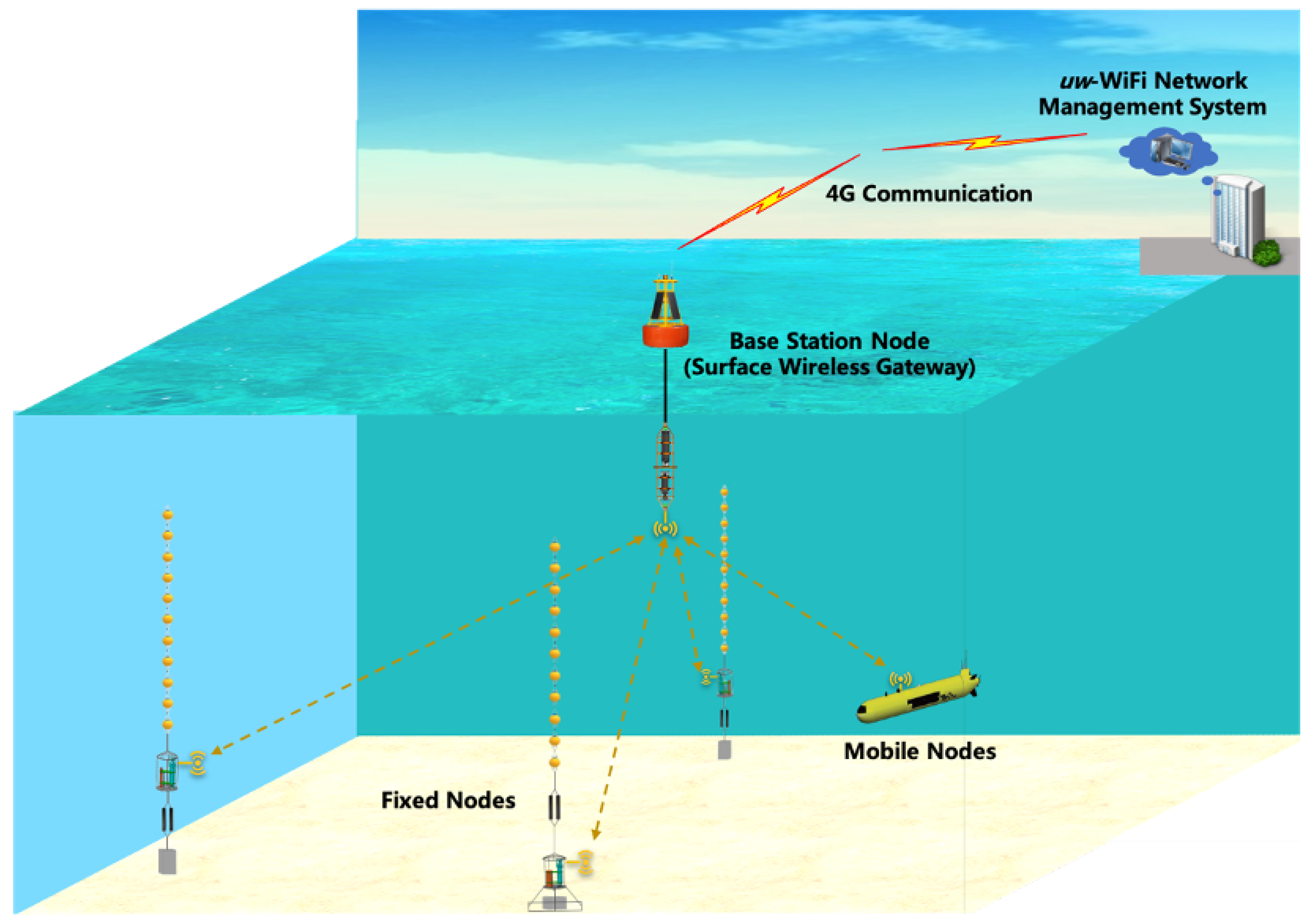
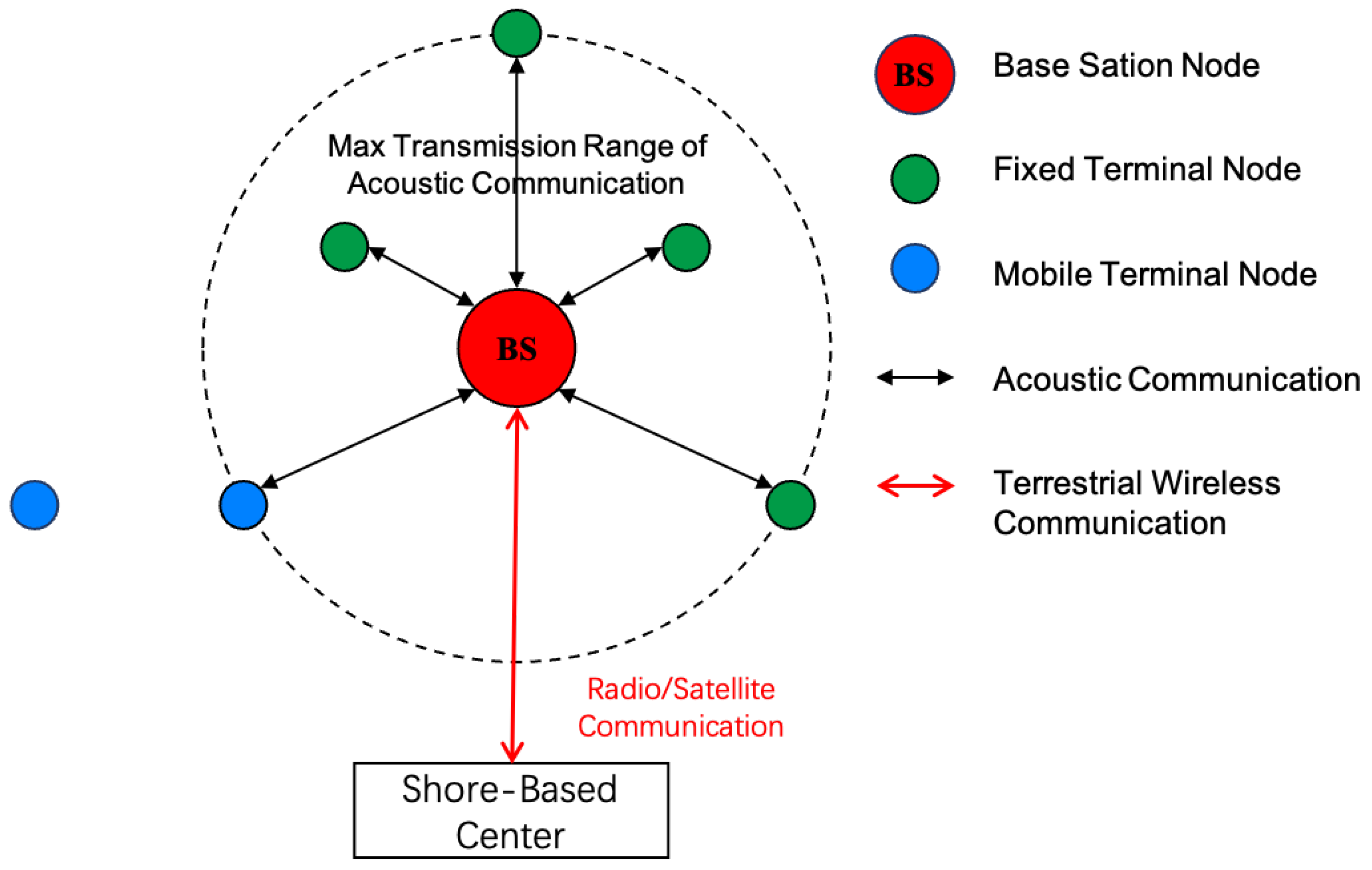
3.2. Architecture of uw-WiFi

The uw-WiFi network operates in a master–slave mode, consisting of one master node and several client nodes. In the uw-WiFi network, the master node is referred to as the Base Station (BS) node, and the client nodes are referred to as Terminal nodes. The main function of the base station node is to collect data reported by all terminal nodes through underwater communication. The base station node also provides access services to all terminal nodes and, when necessary, data exchange between terminals can be facilitated through the base station node. Additionally, the base station node can also act as a gateway node for the network, connecting the terrestrial network with the underwater network, forwarding underwater data to terrestrial users, and forwarding user instructions to specified underwater nodes, enabling bidirectional data interaction between land and underwater. The terminal nodes are responsible for collecting underwater sensor data, performing front-end processing on the sensor data and transmitting the data to the base station node using underwater acoustic communication. The terminal nodes in the network can be both fixed and mobile, such as submersibles and autonomous underwater vehicles (AUVs).
In this network architecture, terminal nodes can join or exit the network flexibly without the need to modify parameters of other terminal nodes in the network. Therefore, if an individual terminal node fails and leaves the network, it can rejoin the network after maintenance without affecting the normal operation of the entire network. Furthermore, this network architecture is advantageous for data transmission of mobile terminal nodes within the network. Mobile terminal nodes can leave the network coverage area for data collection according to task requirements and then return to the network for data transmission. The topology of the uw-WiFi network is shown in Figure 1.
The uw-WiFi underwater acoustic network utilizes the SeaLinx [43] underwater network protocol stack, which is based on a four-layer structure. Inside the protocol stack are the application layer, the transport layer, the network layer, and the data link layer. These layers group different categories of functions according to the task that needs to be performed by UANs. Protocols in the stack can be easily replaced according to different requirements without having effects on other protocols. The message flow in the protocol stack can be seen in Figure 2. The protocol in one layer is separated from protocols in other layers and does not have to know about the tasks performed in another layer, but all protocols can perform excellent cooperative work in the protocol stack. Protocols in the stack can be easily replaced according to different requirements without having effects on other protocols. All these we mentioned make the protocol stack of the layered structure both flexible and safe for the uw-WiFi network.

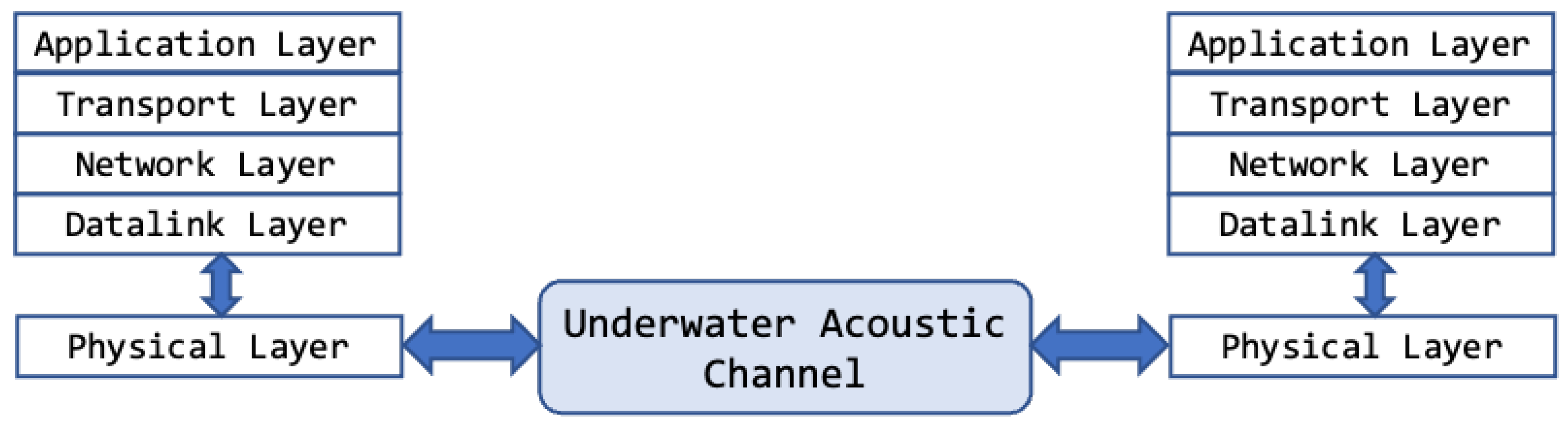
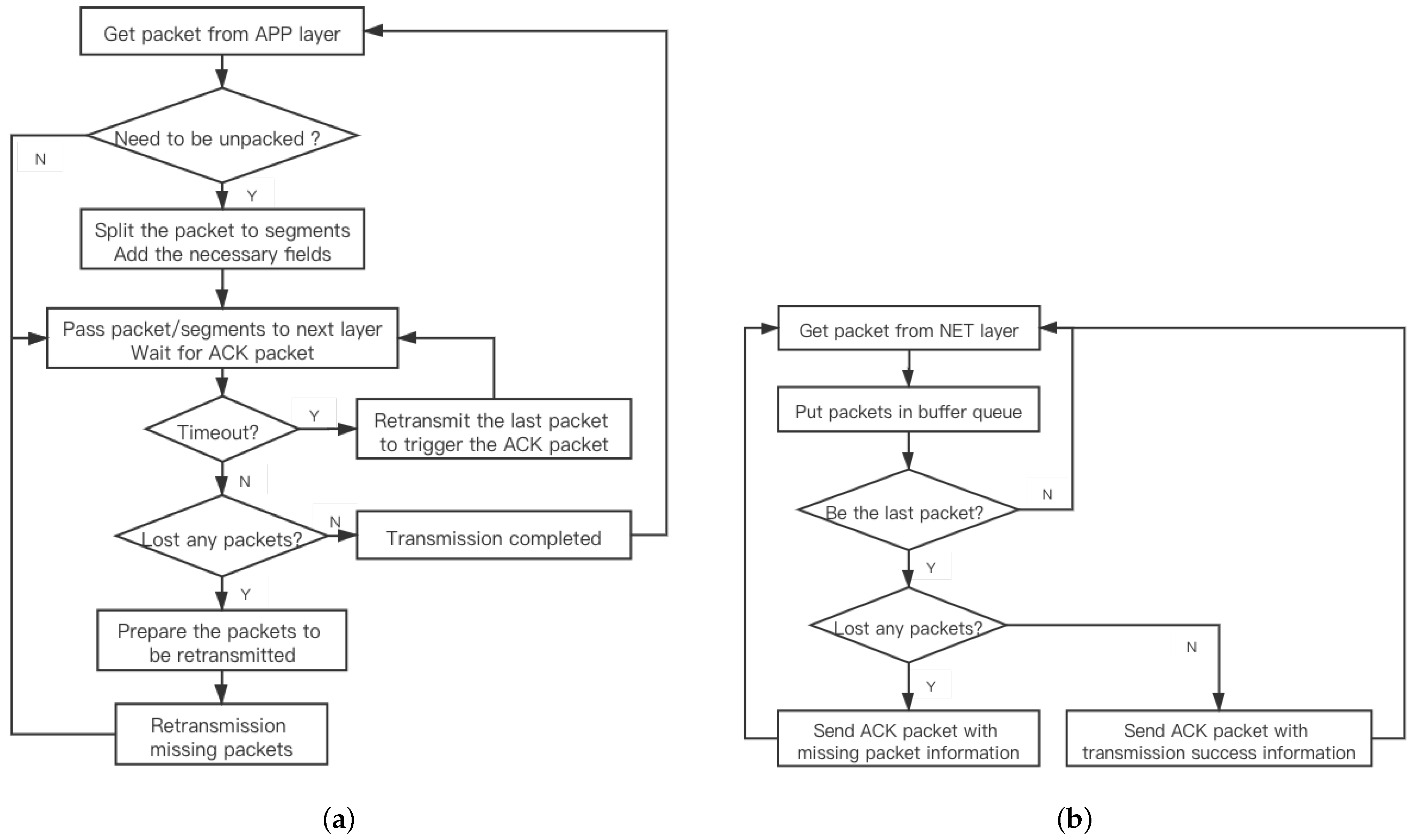
3.3. Design of Protocols for uw-WiFi

The design of protocols needs to take into account the harsh conditions of the underwater environment, such as long propagation delays, low bandwidth, signal attenuation, asymmetric links, and multi-path effects. In this section, we introduce the basic principles of protocol design for uw-WiFi.
Data link layer: This layer is a significant module that provides the point-to-point communication service. The protocols in the data link layer have the objectives of managing and controlling communication channels that are shared by many nodes to avoid collisions and of maintaining reliable transmission conditions while providing energy efficiency, few channel access delays, and fairness.
In this network, we designed a protocol called SDDA [44]. The main principle behind it is to achieve a slotted packet reception at the base station node. This is realized via the base station node’s ability to estimate the propagation and transmission delay of terminal nodes in the network, as depicted in Figure 3.
First, the base station node sends a trigger (TR) packet to notify the terminal nodes within its transmission range to reserve the channel with RTS packets, and then it waits for these RTS packets. The TR packet tells each terminal node how long it should wait after receiving the TR packet before sending its RTS packet. Second, each terminal node that receives the TR packet and that has DATA packets to send fills the RTS packet with the size of these packets and then sends the RTS packet. Next, the base station node estimates the time required by each terminal node to send packets based on the number of packets in each RTS packet. This time information is filled into the CTS packet and broadcast to all terminal nodes, telling each terminal node how long it should wait before sending the data packet after receiving the CTS packet. This step is an important stage for the base station to allocate time slots for the terminal nodes to send data packets. The CTS packet sent by the base station node requests that each terminal node that reserved the channel successfully send DATA packets at the specified time. The base station node will wait for the DATA packets until the time expires. Afterwards, the base station node sends the ACK packet as feedback to notify each node whether the data packets were received successfully or not. Finally, if the base station node has DATA or CTRL packets to send, the packets would be sent following the ACK packet. Then, the base-station sends the TR packet to start a new round of data transmission. According to the above analysis, the information that the base station node provides the terminal node is a countdown duration, not an exact moment. So, there is no need for strict clock synchronization between the base station node and the terminal node, which is also an advantage of this protocol.
This protocol not only accommodates more terminal nodes in the network, but also avoids data conflicts effectively caused by underwater multi-node communication. At same time, by this on-demand scheduling, the SDDA protocol reduces unnecessary time overhead and helps to improve the performance of the network.
Network layer: Compared to terrestrial wireless networks, protocols in this layer have more difficulty in selecting and managing the optimal path for transmitting data from the source node and to the destination node. The issues that routing protocol design should address include the movement of nodes, high and inefficient propagation delay, energy constraints, location estimation, and 3D deployment [45,46]. This is especially important for the uw-WiFi network, whose star network topology means that different categories of routing protocols can be used according to different scenarios and tasks. For example, a static-based routing protocol is satisfied if the main task of the network that contains more static terminal nodes is to collect underwater sensor data. Conversely, for some targeted applications that require more mobility of terminal nodes such as frequently disconnecting and re-establishing the connection with the base station node, a dynamic routing protocol that considers location information and power consumption should be used.
As mentioned earlier, we designed a customized routing protocol based on the architecture and the actual application requirements of the uw-WiFi network. If there are more static nodes in the network and if underwater monitoring or sensing data collection is the main application scenario, the protocol can be configured to provide static routing services. On the contrary, in application scenarios with mainly dynamic nodes, the protocol can be configured to provide a dynamic path planning strategy.
Transport layer: The protocols in transport layer bear the responsibility for the end-to-end data transmission in the uw-WiFi network. Unlike land-based wireless networks, many TCP-like protocols have not been proposed due to the large propagation delay in UANs that significantly influences the performance of end-to-end reliable data transport [47]. Underwater acoustic communication is affected by harsh environments, leading to higher error rates and higher packet loss rate for the network. Packet loss re-transmission is a direct solution, but in cases where the adverse environmental effects persist and continuous packet loss occurs, re-transmitting all data would further occupy the channel and waste valuable power. Therefore, a mechanism is needed to meet the re-transmission requirements of different types of data in different environments within the underwater acoustic network.
We designed a protocol called the Reliable Segmentation Transport Protocol (RSTP) for the uw-WiFi network. When the transport layer gets a jumbo message from the application layer that is beyond its current ability to transmit, the RSTP breaks the message into a group of smaller segments (Figure 4a). The receiving end must wait for all segments, which can then be reassembled into the original jumbo messages and passed on to the application layer with no errors (Figure 4b). Each segment has several additional fields to represent some relevant information, including the total number of segments and the number remaining; the type, ID, and length of the current segment; and the ID of the original message. That makes it possible to provide a selective re-transmission service when packet loss occurs. RSTP can also provide a UDP-like service through the setting of certain parameters, mainly for loss-tolerant connections between applications on uw-WiFi networks.
Application layer: The protocols in this layer provide the rules and formats that govern how data are treated. Specific application protocols define the processes and methodology to deal with the specific type of data, including formatting, packing, sending, and receiving.
We designed different protocols to achieve different network functions. For example, a dedicated protocol has been designed to format and parse the data of a conductive-temperature-depth (CTD) sensor in a terminal node. We also proposed protocols to deal with the image from the underwater camera and navigation data from AUV. Protocols for processing instruction data have been also designed, including checking, setting, and control.

4. A Case Study of the uw-WiFi Network

As a case study, we implement the uw-WiFi network with 5 nodes. The main task of the network is to monitor the underwater environment and collect underwater sensor data. At the same time, users can control the network nodes by sending various instructions. Customized protocols in the transport, network, and data link layers are implemented. We have also implemented some functions to verify that the uw-WiFi network can be applied to the targeted scenarios we mentioned earlier.

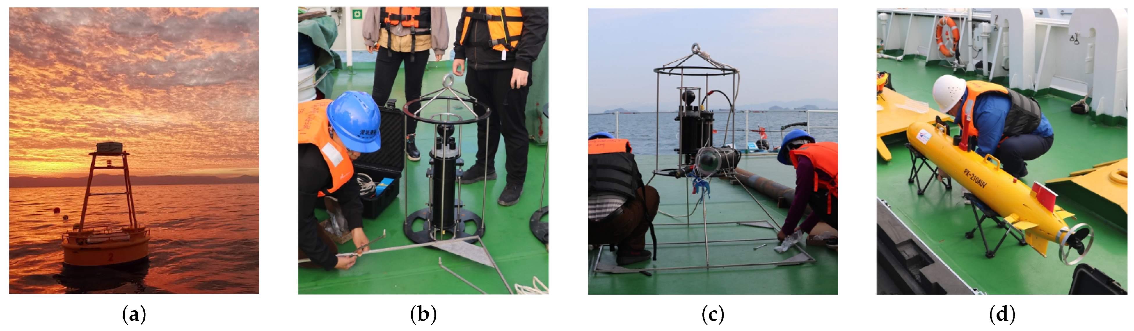
4.1. Network Components

The entire network consists of three parts, including an Underwater Wi-Fi Network Management System, one Network Base Station Node, and four Network Terminal nodes. Figure 5 shows how uw-WiFi network setup.
The main function of the uw-WiFi acoustic network management system is to provide an interactive medium between users and the underwater network. This management system stores and displays the underwater sensor data reported by the uw-WiFi underwater acoustic network. It also provides an interface for sending different network control commands to help users adjust the network operation based on the actual situation.
The Network Base Station Node acts as a gateway and is an important node that connects the onshore network and the underwater network. It is composed of a buoy, a radio communication module, and an underwater acoustic modem. The modem is a crucial component of the underwater acoustic network, and it adopts orthogonal frequency-division multiplexing (OFDM) modulation and demodulation with a center frequency of 24 kHz and a communication bandwidth of 21 kHz to 27 kHz. The data frame consists of a trigger header (HFM), a preamble, and multiple data blocks. Each data frame can contain up to 16 data blocks. The modem offers five communication modes, and the difference lies in the maximum number of bytes that a single data block can carry. This difference reflects the different communication rates of each mode. The physical layer communication rates for each communication mode are shown in Table 1. The communication device integrates an ARM chip and is equipped with an embedded Linux system, enabling it to simultaneously perform underwater communication and underwater networking functions. The deployment of the Network Base Station Node is illustrated in Figure 6a.
The main function of the Network Terminal Nodes is to collect data using the onboard underwater sensors and send them to the base station node. Additionally, they execute corresponding instructions when received. In this shallow water experiment, a total of four terminal nodes were deployed, including three fixed terminal nodes in the form of mooring buoys and one AUV mobile terminal node. Each fixed terminal node consists of an underwater acoustic modem, a battery, and underwater sensors. Similar to the base station node, the modem provides the basic functions of underwater communication and network formation. The battery supplies power to the underwater acoustic network transceiver and underwater sensors. Two fixed terminals are equipped with CTD sensors, and one fixed terminal is equipped with an underwater optical camera. The AUV mobile terminal node is a shallow-water lightweight AUV, which is integrated with an underwater acoustic modem. During the experiment, it uploads its own navigation sensor data, such as heading, speed, and attitude. The deployment of the Network Terminal Nodes is illustrated in Figure 6b–d.

4.2. Protocols and Applications

In this case study, customized protocols mentioned above have been developed and implemented to address the actual scenarios. The SDDA protocol was configured to cache 40 packets in the waiting queue and send up to 10 packets in one sending window. In the network layer, we implemented a custom static routing protocol. When a packet is received by the base station node, the path information of the packet, including its origin, next hop, destination, and the time the packet was received, were recorded. In the RSTP, we configured the maximum segment size, which is derived from a jumbo packet according to the environment.
We implemented different application protocols to process CTD data, image data, and navigation data from the AUV. We can tolerate the loss of CTD sensor data and need to get the navigation data of the AUV in time, so the protocols choose the UDP-like service in the transport layer. However, the image data are a kind of non-loss-tolerant data, which need be delivered with reliability. The reliable transmission services would be chosen to transmit the image data.
We also implemented protocols to deal with the instructions, described as follows.
  • Check the status of the specified terminal node. If the base station node receives the response packet within the specified time, the terminal node is considered to be in good status.
  • Set the transmission mode of the terminal nodes. Users can reset the transmission mode depending on the actual underwater acoustic channel conditions.
  • Set the data generation/send interval of the terminal nodes. The terminal nodes that receive this instruction would execute the new settings.

4.3. Deployment Environment

We conducted experiments in real environments to evaluate the performance of the uw-WiFi network. We deployed the uw-WiFi network in Daya Bay, Guangdong, China. Figure 7 illustrates the area of the network nodes deployed based on the GPS information collected during the experiment. The average water depth of the implement experiment is 7 m. The experiments were conducted in the summer, and it is easy to form a negative gradient sound field in such an environment. Severe multipath effects and propagation losses of underwater acoustic transmission will occur in such environments. The acoustic field environment simulated using Bellhop is shown in Figure 8. The distance between the base station node and each terminal node we deployed does not exceed 3000 m.

4.4. Performance Metrics

Underwater acoustic networks are typically evaluated based on their specific application scenarios. The uw-WiFi underwater acoustic network designed and implemented in this paper is primarily intended for underwater sensor data collection. Based on the characteristics of the uw-WiFi in this scenario, we will use several metrics described below as the evaluation criteria.
  • Data rate represents the number of bits of data transmitted on the channel per second, also known as the bit rate. The unit of this rate is bps (bits per second) or b/s.
  • Data latency indicates the time it takes for data (a packet or bits) to travel from one end of the network to the other, and it typically includes transmission delay and propagation delay.
  • Network packet loss rate indicates the network packet loss during a period of time.
  • Throughput represents the amount of data that passes through a network or interface per unit of time, including all uploaded and downloaded traffic.

4.5. Experiment Results

In this section, we conduct experiments in a real environment to evaluate the performance of the uw-WiFi network and analyze the test results.
  • Data rate & Data latency
The data rate and data latency are considered to be the most important concerns for users. All packets sent in this experiment were generated in specific length and generation intervals. The packet lengths for this test were set to 162 bytes (5 data blocks), 359 bytes (10 data blocks), and 549 bytes (15 data blocks) in TX Mode 1. The packet generation interval is constant in each run of this test. The minimum generation interval was set as 10 s, and the generation interval of each test was increased by 5 s until it reached 80 s. The total duration of the test exceeded 24 h, and the total number of packets sent in each set of experiments exceeded 1500 times. We have calculated the average data latency and data rate of each set of tests when the network is running. The results are also shown in Figure 9.
We defined the data rate as:
d a t a _ r a t e = p a c k e t _ s i z e d a t a _ l a t e n c y .
The results show that high-generation frequency causes a data backlog and even cache overflow at the sending end and also results in larger data latency and a lower data rate at the receiving end. As the generation frequency decreases, the packet latency tends to be closer to the network scheduling overhead based on the protocols in the uw-WiFi network. On the other hand, when the generation interval of packets exceeds the scheduling overhead, the actual data latency in the network would not be affected significantly as the size of the data packet increases.
In addition, CTD data and AUV navigation data were collected during that experiment, as shown in Figure 10 and Figure 11. By adjusting the size of the sensor data and the frequency of data production, we can obtain underwater information in real time.
  • Throughput
Throughput in the uw-WiFi network indicates the amount of data that is successfully delivered between terminal nodes and the base station node within the specified time, measured in bits per second (bps). In this specialized test, each terminal node sent 10 packets continuously to the base station node, and the base station node sent 10 data packets to 2 designated terminal nodes, respectively, after receipt. Specially, the packets do not need to be re-transmitted if packet loss occurs. The packet loss rate was taken into consideration while analyzing experimental results. The results can be seen in the Table 2.
Along with the transmission mode increases, the throughput does increase significantly and up to 3226.67 bps. Due to the poor condition of the underwater acoustic communication channel, each mode experienced varying degrees of packet loss during the tests. The experimental results show that Modes 1 and 2 can adapt to more severe communication channels. Using Modes 3, 4, and 5 could have achieved better performance if the uw-WiFi was deployed in a better environment.
Given that the network can have high throughput performance, we can complete the network function of collecting and transmitting underwater pictures. Figure 12 shows the underwater camera capturing pictures.
  • Network packet loss rate
The uw-WiFi network provides an on-demand scheduling mechanism as mentioned above, and the packet loss in the network is usually caused by a bad underwater acoustic communication environment instead of conflicts. In order to reduce the network packet loss rate, the uw-WiFi network provides up to two re-transmission opportunities. The network packet loss rate (NPLR) is defined below to evaluate the data reliability of the uw-WiFi network.
N P L R = T o t a l n u m b e r o f f a i l u r e s T o t a l n u m b e r o f p a c k e t s g e n e r a t e d
In this group of tests, we deployed 3 static terminal nodes and 1 mobile terminal node. The moving speed of the mobile terminal node is between 1–3 knots. The packet lengths of the static terminal nodes and the mobile terminal node for this test were set to 359 bytes (10 data blocks) and 162 bytes (5 data blocks) in TX Mode 1, respectively. The test packets were generated according to a Poisson process. The average packet generation interval was set to 40 sm which is the expectation of the Poisson process. The test lasted for 4 h without intervention, and the network PLR was counted in real time.
As Figure 13 shows, because of the re-transmission mechanism, the network packet loss rate of static nodes stabilized below 0.62% eventually. However, due to the adverse Doppler effect on signal demodulation, continuous and serious packet loss occurred when the speed of the mobile terminal node increased. The network packet loss rate is greatly reduced when reaching the peak after the re-transmission process.

5. Performance Analysis of the uw-WiFi Network

As mentioned above, uw-WiFi is a network with master–slave architecture, consisting of a base station node and several terminal nodes. The base station node provides network access services to the terminal nodes and, through relevant computations, offers temporal control for the entire network. In theory, a network based on the master–slave architecture can infinitely increase the number of slave nodes while ensuring the reliability of the master node. However, due to factors such as device computing power, network overhead, and deployment costs, infinitely increasing terminal nodes in a network not only does not significantly enhance network performance but also to some extent diminishes network efficiency.
This section will discuss the boundary performance of uw-WiFi networks from the perspectives of network node capacity, number of packets transmitted per terminal node, network throughput, user data latency, and network channel utilization. The following terms are defined as follows:
  • Network node capacity refers to the number of terminal nodes in a network, excluding the base station nodes.
  • Number of packets that a terminal node sent once refers to the number of packets sent by each terminal node within a single time period in the network.
  • Network throughput refers to the total amount of data transmitted through the network within a unit of time, usually measured in bits per second (bps).
  • Network cycle time refers to the duration between when the main node in the network triggers the current round of time-division scheduling and when it initiates the next round of time-division scheduling.
  • Network channel utilization refers to the ratio of the time during which the network transmits valid data to the total time of network operation.

5.1. Network Throughput

In the uw-WiFi network, without considering packet loss and assuming all nodes in the network transmit data at their maximum sending capacity, the maximum network throughput is defined as:
T h r o u g h p u t m a x = T o t a l d a t a T o t a l d e l a y .
Assuming the network node capacity is n, the number of packets transmitted by each terminal node in a single scheduling cycle is m, and the maximum size of each packet is  D S m a x bytes, then the maximum data volume in the network within one scheduling cycle can be calculated as:
T o t a l d a t a = ( n + 1 ) × m × 8 × D S m a x .
In an ideal scenario, the time taken for a single data transmission within one scheduling cycle can be represented as:
T o t a l d e l a y = t T R + 5 t p + t R T S + t C T S + t A C K + ( n + 1 ) t D A T A ,
where  t T R represents the end-to-end time required for a TR Ppacket, t p is the propagation delay,  t R T S is the end-to-end time required for an RTS packet, t C T S is the end-to-end time required for a CTS packet, t D A T A is the end-to-end time required for a DATA packet, and t A C K is the end-to-end time required for an ACK packet. Based on these parameters, the maximum throughput of the network can be obtained as:
T h r o u g h p u t m a x = ( n + 1 ) × m × 8 × D S m a x t T R + 5 t p + t R T S + t C T S + t A C K + ( n + 1 ) t D A T A .
Assuming a propagation delay of 1 s and incorporating the actual data of the modem, the network throughput can be represented as:
T h r o u g h p u t m a x = ( n + 1 ) × m × 4864 9 + 0.32 ( 6 + 2 n 38 + 2 10 n 38 + 7 + 3 n 38 ) + 6.12 ( n + 1 ) m .
The x-axis of Figure 14 represents the number of packets transmitted by each terminal node, while the y-axis represents the network throughput. The curves in the figure represent the throughput achievable under different node capacity conditions. From Figure 14, it can be observed that, regardless of the node capacity in the network, as the number of packets transmitted by each terminal node increases, the network throughput shows a growing trend and eventually stabilizes without significant further growth. However, as the node capacity in the network increases, the magnitude of the increase in network throughput becomes smaller. When there is only one terminal node in the network, the throughput increases by approximately 81.45%. When the network accommodates 20 terminal nodes, the throughput increases by approximately 10.78%.
The x-axis of Figure 15 represents the network node capacity, while the y-axis represents the network throughput. The curves in the figure represent the throughput achievable by the network under different conditions of the number of packets transmitted by each terminal node. Similarly, from Figure 15, it can be observed that, as the number of terminal nodes in the network increases, the number of packets transmitted by each terminal node does not have a significant impact on the throughput. For example, when the number of packets transmitted by each terminal node is 20, the throughput of the network with 20 terminal nodes is only approximately 12.00 bps higher than the network with 3 terminal nodes. When the number of packets transmitted by each terminal node is 60, the throughput of the network with 20 terminal nodes is only approximately 4.07 bps higher than the network with 3 terminal nodes. Therefore, it can be seen that increasing the number of terminal nodes and the number of packets transmitted by each terminal node can indeed increase the network throughput; however, as the quantities continue to increase, the effect on increasing the network throughput becomes less significant.

5.2. Network Cycle Time

The network cycle time primarily affects the user data delay. Ignoring the additional waiting delay caused by excessively high user data generation frequency, a larger single-cycle time means that the interval between each node, including the base station node, sending its own data once within the network is longer. For users, this also means a longer data delay. The x-axis of Figure 16 represents the number of packets transmitted by each terminal node, while the y-axis represents the single-cycle duration of the network. The curves in the figure represent the single-cycle duration of the network under different node capacity conditions.
From Figure 16, it can be visually observed that, regardless of the node capacity in the network, the network cycle time of the network shows a clear increasing trend as the number of packets transmitted by each terminal node increases. Moreover, as the node capacity in the network increases, the magnitude of the increase in the network cycle time also becomes larger. When there is only one terminal node in the network, the network cycle time increases approximately 10.33 times. When the network accommodates 20 terminal nodes, the network cycle time increases approximately 17.12 times. This indicates that, in certain practical application scenarios where there is a relatively high requirement for data timeliness, including too many terminal nodes in the network or transmitting an excessive number of packets per terminal node will significantly reduce data timeliness.
Based on the above analysis, it can be concluded that the throughput and network cycle time of a uw-WiFi network are closely related to the number of terminal nodes in the network and the number of data packets transmitted by each terminal node within a single cycle. However, it is necessary to consider the actual application requirements faced by underwater acoustic networks. In scenarios where real-time data requirements are not high but there is a high demand for network throughput, it may be appropriate to increase the number of deployed terminal nodes and the number of data packets transmitted by each terminal node within a single cycle. For applications that require high data real-time performance, reducing the number of data packets transmitted by each terminal node within a single cycle can shorten the single-cycle duration of the network and increase the refresh rate of user data in the network. At the same time, in practical implementation, the deployment and maintenance of network nodes also incur high costs in terms of time, manpower, and financial resources. Therefore, it is not feasible to deploy an excessive number of terminal nodes in a network.

5.3. Network Channel Utilization

Channel utilization is an important metric for evaluating network efficiency. The channel utilization is also influenced by other factors, such as slot allocation algorithms, collision handling mechanisms, control packet overhead, and slot synchronization accuracy. Therefore, in practical applications, it is necessary to consider these factors comprehensively and perform system-level optimization and adjustments to achieve higher channel utilization.
As mentioned earlier, the uw-WiFi network utilizes the SDDA protocol for underwater acoustic channel allocation and management. The SDDA protocol combines the advantages of TDMA and S-FAMA protocols, and it schedules the channel resources of the network through handshake mechanisms and adaptive computation of slots. Figure 17 compares the network channel utilization of the uw-WiFi network using the SDDA, S-FAMA, and TDMA protocols, where the x-axis represents the packet generation intervals.
As shown in Figure 17, the proposed SDDA protocol exhibits significantly better network channel utilization compared to the S-FAMA and TDMA protocols. The network channel utilization of the uw-WiFi network using the SDDA and TDMA protocols decreases and stabilizes as the packet generation interval increases. The network channel utilization of the uw-WiFi network using the S-FAMA protocol slightly increases with the increase in the packet generation interval. Compared to the S-FAMA protocol, the SDDA protocol not only reduces the handshake information used for channel reservation between nodes but also ensures that there are no conflicts in communication between nodes through slot division. Compared to the TDMA protocol, although the SDDA protocol increases the handshake information in scheduling, it utilizes the handshake mechanism to enable terminal nodes to obtain slots on demand, thereby making efficient use of the channel and reducing idle time waste. Additionally, the SDDA protocol allows terminal nodes to send multiple data packets after each round of channel reservation, whereas the TDMA protocol only allows one data packet to be sent per slot. Under this condition, the SDDA protocol has a significant advantage in channel utilization.

6. Conclusions

In this paper, a master–slave mode uw-WiFi underwater acoustic network is proposed and implemented to address the challenges of small-scale and rapid underwater acoustic networking. The design intention of this acoustic network is to achieve a stable and reliable application in real-world marine environments. In the uw-WiFi underwater acoustic network, different types of underwater fixed nodes and underwater mobile nodes are deployed in combination, according to the requirements of different tasks. This enables real-time, stable, and continuous acquisition of underwater sensor data within a certain underwater range. Additionally, the uw-WiFi underwater acoustic network differentiates between uplink and downlink data priorities, enabling the completion of various functions such as command transmission, execution feedback, and sensor data reporting.
We gave a detailed description of the architecture and protocol design of the uw-WiFi network. As a case study, a uw-WiFi network with five nodes has been implemented. Protocols and functions have been implemented and applied to verify that the uw-WiFi is feasible for the scenarios we targeted. We conducted the experiments in a real environment, and the results show that the uw-WiFi network can not only run stably in the real environment, but also achieve good performance.
We theoretically analyze the key metrics of the uw-WiFi network. We compare the impact of different node capacities and packet quantities on network throughput. We also compare the network cycle time of the network under different node capacities. Finally, we analyze the effect of data generation intervals on the network channel utilization.
We will continue to upgrade this network as our research proceeds. In order to increase network coverage and capacity, more static and mobile nodes will be added to the network. The concept of sub-nets will be introduced. We are committed to solving both underwater communications between multiple sub-nets and the problem of mobile nodes switching networks between multiple sub-nets.

Author Contributions

Conceptualization, J.Z.; methodology, J.Z. and X.P.; software, J.Z., X.P. and M.L.; validation, J.Z., X.P. and M.L.; formal analysis, J.Z., X.P. and M.L.; investigation, J.Z., X.P. and J.G.; resources, J.Z. and X.P.; data curation, J.Z., X.P. and J.G.; writing—original draft preparation, J.Z.; writing—review and editing, J.-H.C. and Z.P.; visualization, J.Z.; supervision, J.-H.C. and Z.P.; project administration, J.-H.C.; funding acquisition, J.-H.C. All authors have read and agreed to the published version of the manuscript.

Funding

This research was supported in part by the National Natural Science Foundation of China under Grant 61971206, Grant 62101211, and Grant U1813217; in part by the National Key R&D Program of China under Grant 2018YFC1405800 and Grant 2021YFC2803000; in part by Overseas Top Talents Program of Shenzhen under Grant KQTD20180411184955957 and Grant LHTD20190004.

Institutional Review Board Statement

Not applicable.

Informed Consent Statement

Informed consent was obtained from all subjects involved in the study.

Data Availability Statement

The data presented in this paper are available after contacting the corresponding author.

Acknowledgments

The authors would like to thank the anonymous reviewers for their careful reading and valuable comments.

Conflicts of Interest

Author Jun-Hong Cui was employed by the company Smart Ocean Technology Co., Ltd. The remaining authors declare that the research was conducted in the absence of any commercial or financial relationships that could be construed as a potential conflict of interest.

References

  1. Cui, J.H.; Kong, J.; Gerla, M.; Zhou, S. Challenges: Building Scalable and Distributed Underwater Wireless Sensor Networks (UWSNs) for Aquatic Applications. Channels 2005, 45, 22–35. [Google Scholar]
  2. Akyildiz, I.F.; Pompili, D.; Melodia, T. Underwater acoustic sensor networks: Research challenges. Hoc Netw. 2005, 3, 257–279. [Google Scholar] [CrossRef]
  3. Sozer, E.M.; Stojanovic, M.; Proakis, J.G. Underwater acoustic networks. IEEE J. Ocean. Eng. 2000, 25, 72–83. [Google Scholar] [CrossRef]
  4. Felemban, E.; Shaikh, F.K.; Qureshi, U.M.; Sheikh, A.A.; Qaisar, S.B. Underwater Sensor Network Applications: A Comprehensive Survey. Int. J. Distrib. Sens. Netw. 2015, 11, 14. [Google Scholar] [CrossRef]
  5. Domingo, M.C. An overview of the Internet of underwater things. J. Netw. Comput. Appl. 2012, 35, 1879–1890. [Google Scholar] [CrossRef]
  6. Ali, M.; Miraz, M.H. A Review of Underwater Acoustic, Electromagnetic and Optical Communications. In Proceedings of the International Conference for Emerging Technologies in Computing, London, UK, 19–20 August 2020; pp. 86–97. [Google Scholar]
  7. Ranjan, A.; Ranjan, A. Underwater wireless communication network. Adv. Electron. Electr. Eng. 2013, 3, 41–46. [Google Scholar]
  8. Stojanovic, M.; Preisig, J. Underwater acoustic communication channels: Propagation models and statistical characterization. IEEE Commun. Mag. 2009, 47, 84–89. [Google Scholar] [CrossRef]
  9. Jiang, Z. Underwater Acoustic Networks-Issues and solutions. Int. J. Intell. Control. Syst. 2008, 13, 152–161. [Google Scholar]
  10. Gupta, O.; Goyal, N.; Anand, D.; Kadry, S.; Nam, Y.; Singh, A. Underwater Networked Wireless Sensor Data Collection for Computational Intelligence Techniques: Issues, Challenges, and Approaches. IEEE Access 2020, 8, 122959–122974. [Google Scholar] [CrossRef]
  11. Coutinho, R.W.; Boukerche, A. Data Collection in Underwater Wireless Sensor Networks: Research Challenges and Potential Approaches. In Proceedings of the 20th ACM International Conference on Modelling, Analysis and Simulation of Wireless and Mobile Systems, New York, NY, USA, 21–25 November 2017; pp. 5–8. [Google Scholar]
  12. Pu, L.; Luo, Y.; Mo, H.; Peng, Z.; Cui, J.H.; Jiang, Z. Comparing underwater MAC protocols in real sea experiment. In Proceedings of the 2013 IFIP Networking Conference, Brooklyn, NY, USA, 22–24 May 2013; pp. 1–9. [Google Scholar]
  13. Curtin, T.B.; Bellingham, J.G.; Catipovic, J.; Webb, D. Autonomous Oceanographic Sampling Networks. Oceanography 1993, 6, 86–94. [Google Scholar] [CrossRef]
  14. Curtin, T.B.; Bellingham, J.G. Progress toward autonomous ocean sampling networks. Deep Sea Res. Part II Top. Stud. Oceanogr. 2009, 56, 62–67. [Google Scholar] [CrossRef]
  15. Rice, J.A.; Creber, R.K.; Fletcher, C.L.; Baxley, P.A.; Rogers, K.E.; Davison, D.C. Seaweb Underwater Acoustic Nets. In Proceedings of the SSC San Diego Biennial Review, San Diego, CA, USA, 4 October 2001; pp. 234–250. [Google Scholar]
  16. Rice, J.; Diego, S. Seaweb Acoustic Communication and Navigation Networks. In Proceedings of the International Conference on Underwater Acoustic Measurements: Technologies and Results, Heraklion, Greece, 28 June–1 July 2005. [Google Scholar]
  17. Rice, J.; Creber, B.; Fletcher, C.; Baxley, P.; Rogers, K.; McDonald, K.; Rees, D.; Wolf, M.; Merriam, S.; Mehio, R.; et al. Evolution of Seaweb underwater acoustic networking. In Proceedings of the OCEANS 2000 MTS/IEEE Conference and Exhibition, Conference Proceedings (Cat. No.00CH37158), Providence, RI, USA, 11–14 September 2000; Volume 3, pp. 2007–2017. [Google Scholar]
  18. Rice, J.; Green, D. Underwater Acoustic Communications and Networks for the US Navy’s Seaweb Program. In Proceedings of the 2008 Second International Conference on Sensor Technologies and Applications (Sensorcomm 2008), Cap Esterel, France, 25–31 August 2008; pp. 715–722. [Google Scholar]
  19. Grund, M.; Freitag, L.; Preisig, J.; Ball, K. The PLUSNet Underwater Communications System: Acoustic Telemetry for Undersea Surveillance. In Proceedings of the OCEANS 2006, Boston, MA, USA, 18–22 September 2006; pp. 1–5. [Google Scholar]
  20. Açar, G.; Adams, A. ACMENet: An underwater acoustic sensor network protocol for real-time environmental monitoring in coastal areas. IEEE Proc. Radar Sonar Navig. 2006, 153, 365–380. [Google Scholar] [CrossRef]
  21. Real-Arce, D.A.; Morales, T.; Barrera, C.; Hernáâs, J. Smart and networking underwater robots in cooperation meshes: The swarms ECSEL: H2020 project. In Instrumentation Viewpoint; SARTI: Vilanova i la Geltrú, Spain, 2016; p. 19. [Google Scholar]
  22. Zhang, S.; Yu, J.; Zhang, A.; Yang, L.; Shu, Y. Marine Vehicle Sensor Network Architecture and Protocol Designs for Ocean Observation. Sensors 2012, 12, 373–390. [Google Scholar] [CrossRef] [PubMed]
  23. Kumar, P.; Kumar, P.; Priyadarshini, P.; Srija. Underwater acoustic sensor network for early warning generation. In Proceedings of the 2012 Oceans, Hampton Roads, VI, USA, 14–19 October 2012; pp. 1–6. [Google Scholar]
  24. Manjula, R.; Manvi, S. Coverage optimization based sensor deployment by using PSO for anti-submarine detection in UWASNs. In Proceedings of the 2013 Ocean Electronics (SYMPOL), Kochi, India, 23–25 October 2013; pp. 15–22. [Google Scholar]
  25. Nain, M.; Goyal, N.; Zhou, R.; Cui, J.; Zhou, S. Localization Techniques in Underwater Wireless Sensor Network. In Proceedings of the 2021 International Conference on Advance Computing and Innovative Technologies in Engineering (ICACITE), Greater Noida, India, 4–5 March 2021; pp. 747–751. [Google Scholar]
  26. Awan, K.; Shah, P.; Iqbal, K.; Gillani, S.; Ahmad, W.; Nam, Y. Underwater Wireless Sensor Networks: A Review of Recent Issues and Challenges. Wirel. Commun. Mob. Comput. 2019, 2019, 20. [Google Scholar] [CrossRef]
  27. Mayberry, S.; Wang, J.; Tao, Q.; Zhang, F.; Song, A.; Hong, X.; Dong, S.; Webb, C.; Dugaev, D.; Peng, Z. First Step Towards UNet: Open-Access Aquatic Testbeds and Robotic Ecosystem. In Proceedings of the 15th International Conference on Underwater Networks & Systems, Shenzhen, China, 22–24 November 2022; Number 10 in WUWNet’21. pp. 1–8. [Google Scholar]
  28. Demirors, E.; Shi, J.; Guida, R.; Melodia, T. SEANet G2: Toward a High-Data-Rate Software-Defined Underwater Acoustic Networking Platform. In Proceedings of the 11th International Conference on Underwater Networks & Systems, Boston, MA, USA, 14–16 November 2016; Number 12 in WUWNet ’16. p. 8. [Google Scholar]
  29. Peng, Z.; Wei, L.; Wang, Z.; Want, L.; Zuba, M.; Cui, J.H.; Zhou, S.; Shi, Z.; O’Donnell, J. Ocean-TUNE UCONN testbed: A technology incubator for underwater communication and networking. In Proceedings of the 2014 Underwater Communications and Networking (UComms), Sestri Levante, Italy, 3–5 September 2014; pp. 1–4. [Google Scholar]
  30. Petrioli, C.; Petroccia, R.; Potter, J.R.; Spaccini, D. The SUNSET framework for simulation, emulation and at-sea testing of underwater wireless sensor networks. Hoc Netw. 2015, 34, 224–238. [Google Scholar] [CrossRef]
  31. Noh, Y.; Shin, S. Survey on MAC protocols in Underwater Acoustic Sensor Networks. In Proceedings of the 2014 14th International Symposium on Communications and Information Technologies (ISCIT), Incheon, Republic of Korea, 24–26 September 2014; pp. 80–84. [Google Scholar]
  32. Chen, K.; Ma, M.; Cheng, E.; Yuan, F.; Su, W. A Survey on MAC Protocols for Underwater Wireless Sensor Networks. IEEE Commun. Surv. Tutor. 2014, 16, 1433–1447. [Google Scholar] [CrossRef]
  33. Mazinani, S.; Yousefi, H.; Mirzaie, M. A Vector-Based Routing Protocol in Underwater Wireless Sensor Networks. Wirel. Pers. Commun. 2018, 100, 1569–1583. [Google Scholar] [CrossRef]
  34. Wang, C.; Zhang, G.; Shao, Y.; Zhang, L. Improvement research of underwater sensor network routing protocol HHVBF. In Proceedings of the 11th International Conference on Wireless Communications, Networking and Mobile Computing (WiCOM 2015), Shanghai, China, 21–23 September 2015; pp. 1–6. [Google Scholar]
  35. Bisht, M.; Gupta , C.P. Distance energy based routing algorithm with priority handling for UWSN. arXiv 2013, arXiv:1310.2518. [Google Scholar]
  36. Coutinho, R.W.L.; Vieira, L.F.M.; Loureiro, A.A.F. DCR: Depth-Controlled Routing protocol for underwater sensor networks. In Proceedings of the 2013 IEEE Symposium on Computers and Communications (ISCC), Split, Croatia, 7–10 July 2013; pp. 453–458. [Google Scholar]
  37. Kang, Y.; Su, Y.; Xu, Y. ACGSOR: Adaptive cooperation-based geographic segmented opportunistic routing for underwater acoustic sensor networks. Hoc Netw. 2023, 145, 103158. [Google Scholar] [CrossRef]
  38. Hussain, A.; Hussain, T.; Ullah, I.; Muminov, B.; Khan, M.Z.; Alfarraj, O.; Gafar, A. CR-NBEER: Cooperative-Relay Neighboring-Based Energy Efficient Routing Protocol for Marine Underwater Sensor Networks. J. Mar. Sci. Eng. 2023, 11, 1474. [Google Scholar] [CrossRef]
  39. Khan, W.; Wang, H.; Anwar, M.S.; Ayaz, M.; Ahmad, S.; Ullah, I. A Multi-Layer Cluster Based Energy Efficient Routing Scheme for UWSNs. IEEE Access 2019, 7, 77398–77410. [Google Scholar] [CrossRef]
  40. Faheem, M.; Tuna, G.; Gungor, V.C. QERP: Quality-of-Service (QoS) Aware Evolutionary Routing Protocol for Underwater Wireless Sensor Networks. IEEE Syst. J. 2018, 12, 2066–2073. [Google Scholar] [CrossRef]
  41. Mukhtiar Ahmed, M.S.; Channa, M. CBE2R: Clustered-based energy efficient routing protocol for underwater wireless sensor network. Int. J. Electron. 2018, 105, 1916–1930. [Google Scholar] [CrossRef]
  42. Zhang, J.; Cai, M.; Han, G.; Qian, Y.; Shu, L. Cellular Clustering-Based Interference-Aware Data Transmission Protocol for Underwater Acoustic Sensor Networks. IEEE Trans. Veh. Technol. 2020, 69, 3217–3230. [Google Scholar] [CrossRef]
  43. Le, S.N.; Peng, Z.; Cui, J.H.; Zhou, H.; Liaod, J. SeaLinx: A Multi-instance Protocol Stack Architecture for Underwater Networking. In Proceedings of the Eighth ACM International Conference on Underwater Networks and Systems, Kaohsiung, Taiwan, 11–13 November 2013; Number 46 in WUWNet ’13. p. 5. [Google Scholar]
  44. Pan, X.; Zhu, J.; Liu, M.; Wang, X.; Peng, Z.; Liu, J.; Cui, J. An On-Demand Scheduling-Based MAC Protocol for UW-WiFi Networks. J. Mar. Sci. Eng. 2023, 11, 765. [Google Scholar] [CrossRef]
  45. Islam, T.; Lee, Y.K. A Comprehensive Survey of Recent Routing Protocols for Underwater Acoustic Sensor Networks. Sensors 2019, 19, 4256. [Google Scholar] [CrossRef] [PubMed]
  46. Li, N.; Martínez, J.F.; Chaus, J.M.; Eckert, M. A Survey on Underwater Acoustic Sensor Network Routing Protocols. Sensors 2016, 16, 414. [Google Scholar] [CrossRef]
  47. Jiang, S. On Reliable Data Transfer in Underwater Acoustic Networks: A Survey from Networking Perspective. IEEE Commun. Surv. Tutor. 2018, 20, 1036–1055. [Google Scholar] [CrossRef]
Figure 1. Topology of the uw-WiFi network.
Jmse 12 00481 g001
Figure 2. Data flow in the uw-WiFi network.
Jmse 12 00481 g002
Figure 3. Timing diagram of SDDA.
Jmse 12 00481 g003
Figure 4. The work flow of the RSTP. (a) Sending side. (b) Receiving side.
Jmse 12 00481 g004
Figure 5. The uw-WiFi network setup.
Jmse 12 00481 g005
Figure 6. The deployment of uw-WiFi network nodes. (a) Base Station Node. (b) Fixed Terminal Node with CTD. (c) Fixed Terminal Node with underwater optical camera. (d) AUV mobile Terminal Node.
Jmse 12 00481 g006
Figure 7. The actual deployment area of uw-WiFi.
Jmse 12 00481 g007
Figure 8. The acoustic field environment simulated using Bellhop. (a) Sound speed profile. (b) Signal energy attenuation simulation.
Jmse 12 00481 g008
Figure 9. The data rate and data latency of test sets with different parameters.
Jmse 12 00481 g009
Figure 10. The CTD sensor data.
Jmse 12 00481 g010
Figure 11. The AUV navigation data.
Jmse 12 00481 g011
Figure 12. Underwater image collection and transmission. (a) Setting up the markers. (b) Image collected.
Jmse 12 00481 g012
Figure 13. Network PLR results of three static terminal nodes and one mobile terminal node.
Jmse 12 00481 g013
Figure 14. The throughput achievable by the network under different node capacity conditions.
Jmse 12 00481 g014
Figure 15. The throughput achievable by the network under different conditions of the number of packets transmitted by each terminal node.
Jmse 12 00481 g015
Figure 16. The network cycle time of the network under different node capacity conditions.
Jmse 12 00481 g016
Figure 17. The network channel utilization under different packet generation interval conditions.
Jmse 12 00481 g017
Table 1. The ability of each transmission mode.
TX_MODEBytes/BlockMax_Blocks/PacketMax_Bytes/Packet
13816608
280161280
3122161952
4164162624
5248163968
Table 2. Results of the throughput test.
TX_MODETotal Data (B)Time (s)Throughput (bps)Packet Loss Rate
129,376401586.0610.00%
263,9364011275.5310.00%
338,3042281344.0030.00%
4121,8244312261.2321.67%
5174,2404323226.6725.00%
Disclaimer/Publisher’s Note: The statements, opinions and data contained in all publications are solely those of the individual author(s) and contributor(s) and not of MDPI and/or the editor(s). MDPI and/or the editor(s) disclaim responsibility for any injury to people or property resulting from any ideas, methods, instructions or products referred to in the content.

