Abstract
Recently, more wind turbine systems have been installed in deep waters far from the coast. Several concepts of floating wind turbine systems (FWTS) have been developed, among which, the semi-submersible platform—due to its applicability in different water depths, good hydrodynamic performance, and facility in the installation process—constitutes the most explored technology compared to the others. However, a significant obstacle to the industrialization of this technology is the design of a cost-effective FWTS, which can be achieved by optimizing the geometry, size, and weight of the floating platform, together with the mooring system. This is only possible by selecting a method capable of accurately analyzing the FWTS-coupled hydro–aero–structural dynamics at each design stage. Accordingly, this paper provides a detailed overview of the most commonly coupled numerical and physical methods—including their basic assumptions, formulations, limitations, and costs used for analyzing the dynamics of FWTS, mainly those supported by a semi-submersible—to assist in the choice of the most suitable method at each design phase of the FWTS. Finally, this article discusses possible future research directions to address the challenges in modeling FWTS dynamics that persist to date.
1. Introduction
The offshore wind industry has experienced continuous growth over the last few years. Recently, more wind turbines have been installed in deeper waters, further away from the coast, comprising a considerable share of offshore wind resources with less turbulence [1]. However, over deep-sea sites, bottom-fixed concepts are no longer viable as these structures are not economical solutions for water depths of more than 50 m [2]. Therefore, several floating wind turbine system (FWTS) concepts have been developed for use in deeper waters [3,4]. Among these floating concepts, the semi-submersible platform, stabilized mainly by buoyancy, is a promising technology and is the most explored technology compared to the others. This is due to the applicability of these platforms in different water depths, their good hydrodynamic performance, and facility in the installation process [3,5,6].
Several examples of commissioned semi-submersible FWTS include the 2 MW WindFloat semi-submersible in Portugal [7], 3 × 8.4 MW WindFloat Atlantic semi-submersibles in Portugal [8], the 2 MW Fukushima Mirai 4-column semi-submersible in Japan [9], the 7 MW Fukushima Shimpuu V-shape 3-column semi-submersible [9], and 5 × 9.5 MW plus 2 MW Kincardine semi-submersibles in Scotland [10]. Several FWTS are under construction, such as the 5 MW Eolink 4-column semi-submersible in France and the 10 MW concrete OO-Star Norway semi-submersible [8]. Several popular semi-submersible configurations include the WindFloat, the braceless platform, and VolturnUS-S, as shown in Figure 1 [11,12,13,14,15].
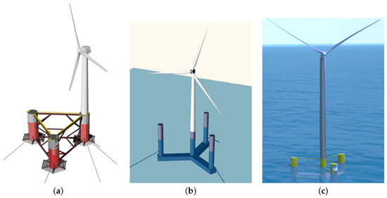
Figure 1.
Popular semi-submersible configurations. (a) the WindFloat platform (image courtesy of Principle Power) [16]; (b) the braceless platform [17]; (c) the VolturnUS-S platform [13].
Figure 2 depicts the layout of two semi-submersible platforms. Figure 2a presents the DeepCwind semi-submersible platform [18], designed within phase II of the Offshore Code Comparison Collaboration Continuation (OC4) project to support the National Renewable Energy Laboratory (NREL) offshore 5-MW wind turbine [19]. Figure 2b shows the UMaine VolturnUS-S reference platform, which was developed to sustain the IEA 15-MW Offshore Reference Wind Turbine (also shown in Figure 1c) [13]. Semi-submersible platforms may possess different offset columns. As shown in [20], increasing these columns can reduce the platform motions. Although most of the semi-submersibles are made of steel, there is a tendency to use concrete for FWTS structures owing to lower construction costs, as well as the superior durability and fatigue resistance of concrete compared to steel [21,22,23,24].
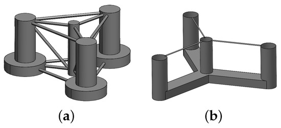
Figure 2.
Two examples of semi-submersible platforms with three offset columns. (a) DeepCwind semi-submersible platform; (b) UMaine VolturnUS-S Reference Platform.
Nonetheless, FWTS are less mature than their bottom-fixed counterparts owing to their more complicated operating conditions and higher prices. The FWTS are subject to loads emanating from several sources, namely wave, current, wind, and, in certain locations, ice [25,26]. Although the similarities between FWTS and floating platforms in the oil and gas industry lead to a partial transfer of technology [27], there are numerous differences between the two industries, such as the presence of aerodynamic loads acting on wind turbines, which significantly affect the dynamics of FWTS and give rise to several new technical challenges [25,28]. For instance, the coupled current–wave–wind loads acting on the FWTS, as shown schematically in Figure 3, may cause large motions of the platform across the structure’s degrees of freedom, and combined with the aeroelastic deformations of the blades, results in highly dynamic inflow to the turbine rotor, affecting the structural integrity of the turbine [29,30]. Furthermore, to ensure safe turbine operations, platform motions induced by offshore environmental loads need to be restricted to an acceptable limit [31]. Generally, large motions are considered undesirable for floating wind turbines due to the possibility of excessive displacements at the top of the tower. Therefore, several strategies have been proposed in the literature to mitigate the motions of FWTS [32,33,34], where tuned mass dampers and tuned mass absorbers constitute the most popular methods for this purpose [35,36,37].
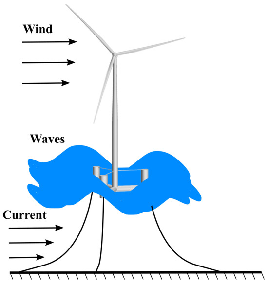
Figure 3.
A FWTS subject to loads emanating from several sources, such as waves, currents, and wind.
Accordingly, floating wind turbines are complex systems subject to coupled hydro-aerodynamic loads, and a better understanding of the behavior of these machines, which is substantial for their efficient design, requires the accurate evaluation of the nature and order of the coupled loading on the structure. The design of a cost-effective FWTS is a major obstacle to the industrialization of this technology [21]. Cost reduction can be achieved by optimizing the geometry, size, and weight of the floating platform, along with the mooring system, anchors, and installation and maintenance processes [5,21,38]. Further cost reduction, particularly the levelized cost of energy, can be achieved by improving the power production by minimizing the platform’s motion, a function of platform geometry, control system, and mooring system [39]. This is only possible by selecting a method that can accurately analyze the coupled hydro–aero–structural dynamics of FWTS at each design stage while incorporating control algorithms, such as power and pitch control [40,41]. Thus, a rather detailed overview of the basic assumptions, formulations, accuracies, and computational demands of the most common methods capable of evaluating the coupled behavior of FWTS in various design stages is required. This provides the necessary knowledge to identify the most suitable method at each design stage. For this purpose, based on the review carried out in this paper, a wide range of methods with different fidelities, as shown in Figure 4, can be used.
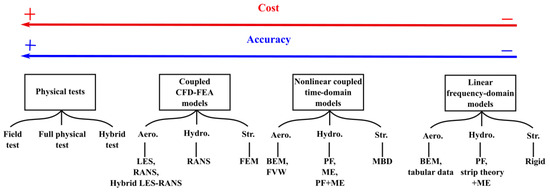
Figure 4.
Methods for evaluating the coupled hydro–aero–structural dynamic behavior of FWTS.
Generally, from right to left, the fidelity increases. The higher the method’s fidelity, the more closely it represents reality by producing more detailed information. However, this comes at the cost of more computational demand and less efficiency. Therefore, the choice of a method at each design stage is a compromise between the accuracy and computational cost.
The simplest methods, as shown on the extreme right of Figure 4, are the linear frequency-domain models with the lowest levels of fidelity, which, due to their ability to provide results in a short time period, are suitable in the early conceptual design phases for sizing and optimization purposes [42]. The hydrodynamics and aerodynamics of rigid FWTS structures are evaluated by the strip theory based on potential flow (PF) together with Morison’s Equation (ME) and a simplified blade element momentum (BEM) approach or tabular data, respectively. In this stage, in addition to structural sizing and static analysis, one must also optimize the response amplitude operators (RAOs) [43]. QuLAF [44] and SLOW [45] codes are examples of low-fidelity frequency-domain tools.
Fully coupled nonlinear time-domain models, used at the basic design stages, are categorized as mid-fidelity models (see Figure 4). These models are more accurate than the low-fidelity tools, which come at the cost of higher computational demand. The aerodynamic part is modeled using either the BEM, the generalized dynamic wake (GDW) model, or the free vortex wake (FVW) method. Note that, in the case of FWTS, the large blade deformations combined with the platform motions may lead to an interaction of the blades with their own shed vortices, which is a violation of basic assumptions of the BEM method [29,46]. In this regard, the FVW is more capable of modeling these complex physics than the BEM method while maintaining the computational cost to an acceptable level. The hydrodynamic loads are modeled based on PF, ME, or a combination of them. Further, the structural dynamics are modeled using multi-body dynamics (MBD), where flexibility is considered in selected components, such as turbine blades and towers. Due to the efficiency and accuracy offered by the MBD for slender bodies, it has become a common tool for wind turbine structural simulations [47].
The mid-fidelity simulation tools based on nonlinear time-domain methods are used for the analysis of dynamic responses of FWTS under a variety of operating and extreme conditions. These tools, through time-domain analysis, allow the adequate assessment of the impact of fatigue and extreme loads on FWTS in various operational and extreme conditions [48]. These tools are also excellent for the control design of the floating offshore wind plant. Note that the control design can be more complex for this technology, as the objective function is established in order to fulfill the following obligations: the optimization of energy production, as well as a reduction in structural loads and platform motions [49,50,51,52,53,54,55,56,57]. The OpenFAST software from NREL is an example of these tools, which can perform real-time coupled hydro-aero-servo-elastic simulations for FWTS [58,59].
Next, as presented in Figure 4, are the high-fidelity methods based on both finite element analysis (FEA) and computational fluid dynamics (CFD). These tools are employed in the final phases of the project where further investigations are required for extreme conditions, as well as intricate flow conditions, e.g., vortex detachment from heave plates [48]. These models involve less parameterization than the other categories, making them computationally more expensive. These models are also suitable for fine-tuning the design, as well as the calibration of the low- and mid-fidelity models [48,60,61,62,63,64]. CFD uses either large eddy simulation (LES), Reynolds-averaged Navier–Stokes (RANS) equations, or hybrid LES-RANS, to predict the aero-hydrodynamic loads acting on FWTS. Unlike BEM and FVW methods, which rely on external aerodynamic load inputs and semi-empirical corrections to account for 3D effects, dynamic stall, etc. CFD naturally takes all these effects into account. CFD can also better capture the turbulent wake behind a turbine, which leads to transient loads on the downstream machines in a wind farm.
Furthermore, the three-dimensional FEA with sufficient details can better capture complex blade deformations at a higher computational cost than MBD, in which the blades are modeled as one-dimensional beams. Structural failure often emanates from local stress raisers, which the MBD method cannot adequately capture. Despite this, the MBD method can provide reasonable boundary conditions for local finite element analyses.
High-fidelity tools are an attractive option for evaluating FWTS dynamics; however, the results of these tools depend on several factors, such as temporal and spatial resolutions, turbulence modeling, free surface modeling, etc. Accordingly, reliable measurements from physical testing, including hybrid testing, full physical testing, and field testing, as shown in Figure 4, are required to gain more confidence in these numerical tools.
Therefore, the low-, mid-, and high-fidelity models, as shown in Figure 4, are obtained by combining numerical models that can evaluate the structural dynamics, hydrodynamics, and aerodynamics of FWTS at different levels of accuracy. As one advances in the design stages, more accurate and detailed methods become essential.
The present paper aims to provide a detailed overview of the most common coupled methods, as depicted in Figure 4, including their basic assumptions, formulations, limitations, and costs used for FWTS, mainly those supported by a semi-submersible, to assist in the choice of the most suitable method at each design stage of the FWTS. Note that several review papers are available on the hydro–aero–structural dynamic evaluation of FWTS [5,8,25,30,48,65,66,67,68].
In this regard, experimental testing and numerical models employed to assess FWTS are reviewed in [8]. However, full physical testing, field testing, numerical methods such as FVW methods, structural dynamics, and nonlinear second-order wave loads are not covered. An overview of the numerical methods, as well as the physical and hybrid tests, are covered in [48]. However, the field tests, as well as the physical basis and formulations of the numerical models, are not presented. An overview of the coupled numerical models for optimizing an FWTS structure in conceptual, basic, and detailed design stages is presented in [5]. An overview of the coupled numerical tools and full physical tests for FWTS are presented in [25]. A review of the experimental and numerical methods is presented in [65], without any details about numerical methods. A general review of numerical and physical models is presented in [30]. The physical and hybrid model tests are reviewed in [66,67,68].
The present review can be considered one of the few works where the basic assumptions, formulations, limitations, and costs of the most popular methods, as well as their recent advances—for analyzing the coupled dynamics of floating wind turbines—are investigated in detail. Furthermore, based on this review, several necessary future research areas are identified and recommended for academic researchers. Therefore, the present review is built upon the previous review efforts by providing a more detailed and up-to-date overview of the state of the art of the most popular physical and numerical coupled modeling techniques for FWTS, as presented in Figure 4.
The paper is organized as follows: Section 2 presents the low-fidelity linear frequency-domain models. Afterward, the nonlinear coupled time-domain methods are described in Section 3. This is followed by the presentation of the high-fidelity modeling techniques of FWTS in Section 4. Moreover, some final notes about numerical models are presented in Section 5, and after that, Section 6 focuses on physical testing. Finally, a summary and conclusions are presented in Section 7.
2. Low-Fidelity Methods—Linear Frequency-Domain Models
These models are based on a linear frequency-domain mathematical model capable of providing steady-state responses for the FWTS [42,69,70]. The FWTS responses are computed using the following six DOF equations [70,71]:
Here, denotes the frequency of the incident wave, denotes the DOF dynamic response of the FWTS, denotes the excitation forces and moment vectors due to wind and waves, M denotes the FWTS mass and inertia matrices, A denotes added mass and inertia matrix, B denotes the damping matrix, and C denotes the restoring matrix. Note that matrices A and B contain contributions from aerodynamics and hydrodynamics, while the C matrix includes mooring loads, in addition to hydrostatic forces. Mooring loads are computed using either analytical equations based on a simple linear spring model or a quasi-static approach [30,44,69,70,72]. The hydrodynamic loads are estimated using a linearized PF theory or strip theory combined with a linearized ME [70,71,73]. The ME may be modified to account for the effect of heave plates [74]. Additionally, aerodynamic loads are considered as a point force at the hub, computed using either a steady-state BEM method or tabular pre-computed data [44,69,71,73]. Note that these models can typically capture only the rigid-body dynamics [30,45,75].
Examples of these models are the open-source frequency-domain code developed in [69], as well as the in-house codes developed in [71,73,76].
3. Mid-Fidelity Methods–Nonlinear Coupled Time-Domain Models
3.1. Hydrodynamics
Both PF and ME are employed for the assessment of the hydrodynamic behavior of an FWTS based on the characteristic length of the floating platform compared to the incident wavelength [77,78,79].
In this regard, when the characteristic length of the floating platform (D) is much larger than the incident wavelength (), the diffraction theory from the linear PF is used to assess the hydrodynamic loads.
The governing equation of the PF theory (obtained by assuming the flow) is incompressible, inviscid, and irrotational. Thus, there will be a velocity potential , whose gradient describes the velocity field as follows:
This Laplace equation is solved using proper linearized boundary conditions, as shown in Figure 5. In this Figure, n is the vector normal to the body surface. Thus, having calculated the velocity potential and, as a consequence, the velocity components, the pressure on the surface of the floating structure is computed using Bernoulli’s equation. Solving this equation with linearized boundary conditions leads to deriving the linear (Airy) wave theory for surface propagating waves. Although other wave theories, like stream functions and stokes, are used to compute wave kinematics based on wave steepness and water depth, the linear Airy wave theory is the most predominant wave theory employed in the offshore industry [30,77,78,80].
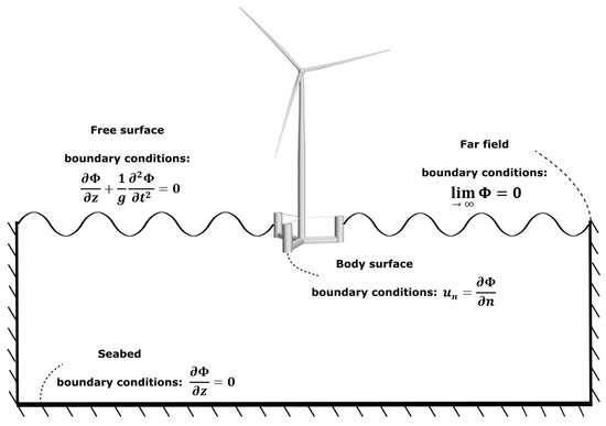
Figure 5.
Linearized boundary conditions typically used in the linear potential flow theory.
To compute the hydrodynamic loads, the incident, diffraction, and radiation wave linear potentials are obtained [79,81,82,83]. Note that as the linear assumption is employed, it is possible to consider that the potential function is a summation of these three potential functions, as follows:
where is the velocity potential related to the incident waves, is the velocity potential related to the diffraction of the incident waves, and is the velocity potential related to the radiation.
The radiation part is related to the case without the presence of any incident waves, and the floating platform is forced to oscillate along its DOF of motion, as shown schematically in Figure 6, which leads to the calculation of added mass and damping loads [81].
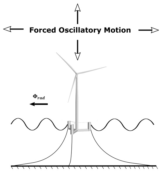
Figure 6.
The radiation problem related to an FWTS.
The diffraction part is related to the case where a floating platform is fixed, causing the scattering of the incident waves, as shown schematically in Figure 7. The diffraction loads come from the undisturbed pressure field (Froude–Krylov) and the disturbed pressure field due to wave scattering (diffraction) [79].
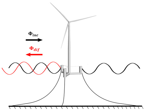
Figure 7.
Velocity potential related to the diffraction of the incident waves to an FWTS.
Note that numerical solutions are obtained using the panel methods where the floating platform is discretized into a limited number of panels [84,85,86,87]. A convergence study may be required to determine the minimum number of panels to obtain a precise solution [85,87].
On the other hand, for [81], the diffraction effects are negligible, and the semi-empirical ME capable of accounting for viscous effects can be used for the calculation of hydrodynamic loads [77,78,83]. The total hydrodynamic load acting on each structural element modeled as a line beam, considering the local velocity and acceleration of the floating system to account for the structure’s motion effects, is estimated as follows:
Here, is the drag coefficient, is the added-mass coefficient, u and are the water particles’ velocity and acceleration, and and are the velocity and acceleration of the floating structure.
To ensure the accuracy of the ME, a proper estimation of the inertial and drag coefficients is crucial [88]. A wide range of methods, from high-fidelity experiments and CFD to semi-empirical equations, can be used to determine these coefficients [89,90]. To include the loads due to the water current, one needs to modify the velocity of water particles to account for the presence of the current.
Note that the ME may be combined with the strip theory to calculate both the linear wave loads and nonlinear viscous loads for slender structural elements [91]. The strip theory in hydrodynamics, as in the BEM theory in aerodynamics, splits the slender structure into a finite number of strips, where two-dimensional hydrodynamic loads are utilized to calculate the overall hydrodynamic forces acting on the structure [81].
Most of the time—as the part of the FWTS in contact with water has members with characteristic lengths that are both much larger and smaller than the incident wavelength—a combination of ME and PF is employed to calculate the hydrodynamic loads due to the viscous drag, as well as the incident, radiation, and diffraction wave potentials [18,83,92].
Note that the predictions provided by linear potential flow theory are inadequate for several cases, such as severe sea states with platforms experiencing large motions, an accurate description of the horizontal motions of a moored platform, and a reliable determination of the excitations related to semi-submersible natural frequencies in the horizontal plane, which typically fall outside the wave-excitation frequency region [83,89,93,94,95]. To overcome these limitations, it is necessary to consider the nonlinear second-order or higher-order effects [83,92,93,96,97,98].
The second-order effects, which are functions of the square of wave height, are commonly considered by using quadratic transfer functions (QTFs) obtained from the second-order potential-flow problem, which requires detailed knowledge of the first-order potential quantities [81,93,94,99]. In this regard, second-order hydrodynamic loads are expressed in terms of the sum and difference of frequencies of sets of two incident waves with amplitudes and and frequencies and , typically using the following double Fourier transform [93,100]:
where and , which are the QTFs to be determined, represent the ith component of sum- and difference-frequency second-order loads, and the asterisk (*) is an indication of the complex conjugate. Note that, for (diagonal terms), the difference-frequency term results in mean hydrodynamic loads, also known as mean-drift loads, which are responsible for the average displacement of floating platforms from their undisturbed initial positions [101,102].
The full sum- and difference-frequency QTF matrices can be computed using available hydrodynamic codes such as the WAMIT, ANSYS-AQWA, and WADAM modules from the SESAM code [12,98,101,103,104,105,106]. Alternatively, as outlined in [93], one can make use of the symmetry properties of the QTFs by dividing the matrices into three different regions, , , and , to reduce the numerical difficulties and computational costs.
Thus, the frequencies in the second-order effects contain the sum and difference of the frequencies of the waves that make up the irregular sea state [107,108]. The high-frequency hydrodynamic loads emanating from the sum of frequencies may lead to higher ultimate and fatigue loads due to the excitation of structural natural frequencies, especially in the case of fixed-bottom and tension-leg offshore wind turbines [100,101,105,108,109]. The low-frequency hydrodynamic loads originating from the difference of frequencies are extremely important for an optimum mooring system design for floating structures [83,92,93,95,96]. This is because a moored floating platform, unlike an unrestricted platform, has natural frequencies in the horizontal plane, generally smaller than the frequency range of the incident waves. The natural frequencies in the horizontal plane are, in fact, excited by the low second-order frequencies emanating from the second-order potential problem. Thus, in the horizontal plane, low-frequency second-order hydrodynamic loads can cause large-amplitude motions (commonly called slow drift motions) in the FWTS, an effect that is not captured by a first-order PF theory [110,111]. This shortcoming of the first-order PF theory can lead to a significant underestimation of FWTS motion responses and, as a result, lead to an inaccurate estimate of the loads acting on the mooring system in the design process. Low-frequency second-order hydrodynamic loads are required to be considered in a coupled dynamic analysis of an FWTS, provided that the loads acting on the mooring lines are of interest. Consequently, increasing attention has been given to the evaluation of the second-order low-frequency hydrodynamic loads in the case of FWTS [98,112,113,114].
Due to its complexity, using the full QTF matrices is sometimes avoided in the offshore industry, and instead, Newman’s approximation has been the most common approach to account for second-order effects. This method estimates the slow-drift forces based on the symmetry of the matrix of the difference-frequency QTF and the mean drift forces [115]. However, the reliability of this method is questionable for intermediate and shallow waters [98,100,113,116].
Another option to compute the matrix of the difference-frequency QTF is the white-noise approach proposed in [116,117]. In this approach, by decoupling the degrees of freedom of motion, it is assumed that the slow-drift motion is excited mainly by a limited portion of frequencies around the platform’s natural frequency, and consequently, the spectrum of the second-order force can be considered constant within this band. The advantage of this method is that the QTF matrix is computed based only on the sets of two frequencies, whose difference gives the drift motion natural frequency.
To improve the predictions of second-order wave loads, one can use the results from wave basin tests or high-fidelity simulations to tune the QTFs obtained from PF solvers [63,118,119]. For instance, the second-order difference-frequency loads are evaluated in [120] using both CFD simulations and physical tests in five different bichromatic incident wave pairs [121]. The platform model is a simplified version of the OC5-DeepCwind floater [83], where only the three cylindrical lateral columns are considered. The bichromatic wave pairs are selected in such a way that they result in a different frequency near the platform surge and pitch natural frequencies. To obtain the quantities of interest, which are typically the amplitude of low-frequency hydrodynamic loads in the predetermined direction, fast Fourier transforms are applied to the time series of hydrodynamic wave loads. As recommended in this study, in the case of CFD simulation, the use of a relatively fine grid close to the free surface interface is necessary for accurate modeling of bichromatic incident waves and, consequently, accurate prediction of difference-frequency hydrodynamic loads.
Based on the QTFs obtained from CFD simulations and physical tests, the values of the QTFs calculated from PF solvers can be modified and then incorporated in the time-domain simulation tools for FWTS to have a more accurate prediction of hydrodynamic wave loads of low frequency [62].
The reason for considering bichromatic waves rather than fully irregular sea states is twofold [120]. First, due to the small repeat periods of the adopted bichromatic incident wave pairs, which are around 100 s at full scale, only runs with a few repeat periods are needed to capture the low-frequency effects based on CFD simulations. This significantly reduces the computational cost compared to a full irregular sea state simulation, in which typically up to 3 h of physical time is required. Secondly, using bichromatic waves, it is possible to make a direct comparison between the low-frequency hydrodynamic loadings obtained from the CFD or physical tests and PF-based QTFs. Consequently, this facilitates the calibration of QTFs.
To consider second-order effects, alternatively, the full second-order velocity potential can be obtained through perturbation analysis, and then the loads can be calculated through direct integration of the pressure acting on the instantaneous wetted surface of FWTS [94,95,99,122]. Second-order loads are computed more accurately using this approach, which is computationally more demanding.
Another important subject is the assessment of the dynamic responses of the FWTS subject to extreme sea states such as freak waves [123,124,125]. These extreme waves can be generated by dividing the wave spectrum into uniform N parts, which are then summed up after modifying the initial phases of some of these components.
Finally, to perform the time-domain simulations using the frequency-dependent loads presented so far, the Cummins equation, where a convolution integral formulation is used to capture the fluid memory effects, is employed [12,84,126,127]:
Here, M is the inertia matrix, is the added-mass matrix at infinite frequency, C is the restoring (hydrostatic stiffness) matrix, is the displacement vector of the floating platform, is the retardation function (fluid memory), and denotes the time-varying external forces.
3.2. Aerodynamics
3.2.1. BEM Method
The BEM theory is the most popular method to evaluate wind turbine aerodynamics. This method is a combination of two theories: blade element and momentum. The blade element theory considers that the blades comprise a finite number of elements with negligible interaction with the nearby elements. It is further considered that these elements operate as two-dimensional airfoils. The momentum theory is also used to calculate the induced axial and tangential velocities. Thus, combining these two theories gives origin to the BEM theory, an iterative process to evaluate turbine aerodynamics.
In this regard, the elements along the blade span located at the radial position of r, which extend to , as shown in Figure 8, affect the airflow momentum that travels across the circular ring area covered by these rotating elements due to their aerodynamic loads.
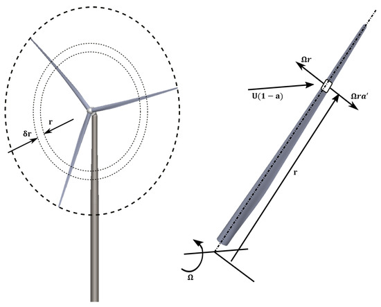
Figure 8.
Elements along the blade span located at the radial position of r, extending to , affect the airflow momentum that travels across the circular ring area covered by these rotating elements due to their aerodynamic loads.
The element’s aerodynamic loads are calculated using the two-dimensional airfoil properties based on an angle of attack (), which is defined in terms of the total incident wind speed, W, written as follows, based on Figure 9:
where and a are the tangential and axial induction factors, U denotes the freestream wind speed, and denotes the angular rotor speed.
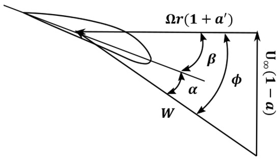
Figure 9.
angle of attack, pitch angle, angle enclosed by the rotor plane and the total incident wind speed W.
To improve the predictions given by the BEM method, several corrections are introduced to account for the effects such as blade-tip and -root losses, a finite number of blades, tower shadow, three-dimensional stall delay, dynamic stall, yawed condition, unsteady loading, and dynamic inflow [29,128,129,130,131,132].
However, both the large platform motions and blade aeroelastic deformations result in the rotor interaction with its own shed vortices, a condition where the BEM method may give unrealistic results [75,92,133,134]. FWTS are more frequently subject to yawed inflow conditions since they have little yaw stiffness. However, the BEM theory was originally developed for the inflow condition perpendicular to the rotor plane, and the commonly used corrections may give erroneous results [92,114,133,135].
To evaluate turbine aerodynamics, the GDW model can be used alternatively to intrinsically consider the three-dimensional effects and dynamic wake effects [136,137]. The GDW method is normally employed to model the tip losses at the blades and the performance of a turbine under yawed conditions more accurately. However, its limitations at small wind speeds lead to unstable computations [138]. Generally, the BEM method is more commonly used in the coupled analyses of FWTS. This can be deduced from the availability of this method in most of the codes used for the investigation of the coupled dynamics of FWTS, such as Bladed, OpenFAST, OrcaFlex, SIMA, SESAM, and HAWC2 [83,128,139,140,141,142,143].
3.2.2. FVW Method
The FVW method is capable of characterizing the wake evolution of a wind turbine over time, which may give more reliable predictions in the case of FWTS due to the possibility of movement of the rotor into its own wake [29,144,145].
The FVW belongs to vorticity-based methods, such as the vortex lattice method (VLM) [128,130,146], assuming that the flow is inviscid, incompressible, and irrotational [147], and it has long been used in the field of wind energy [148,149,150,151,152,153].
The FVW method is used to solve the turbine wake in a time-accurate manner, in which, contrary to the prescribed vortex methods, the convection, stretching, and diffusion of vortices are captured [29]. This is performed using a Lagrangian approach that can discretize the turbine wake into Lagrangian markers, defined as functions of the wake age and azimuthal blade location , as shown in Figure 10 [29,147]. A wide range of methods is available for the representation of the wake using Lagrangian markers [150], such as the hybrid lattice/filament, which is used within the OpenFAST code [145] (see Figure 10). Over the near-wake region, a lattice method is used, as shown schematically in Figure 10. A user-defined angle is used to specify the near-wake span [154], which is usually assumed to be degrees [154]. This angle may not be sufficient for challenging operating conditions, e.g., high thrust conditions [145]. The near-wake region is followed by instantaneous wake aggregation into tip vortices, which are considered the principal flow characteristics over the rest of the wake [155]. Straight-line vortex filaments with second-order accuracy are used to connect the Lagrangian markers together [155] (see Figure 10).
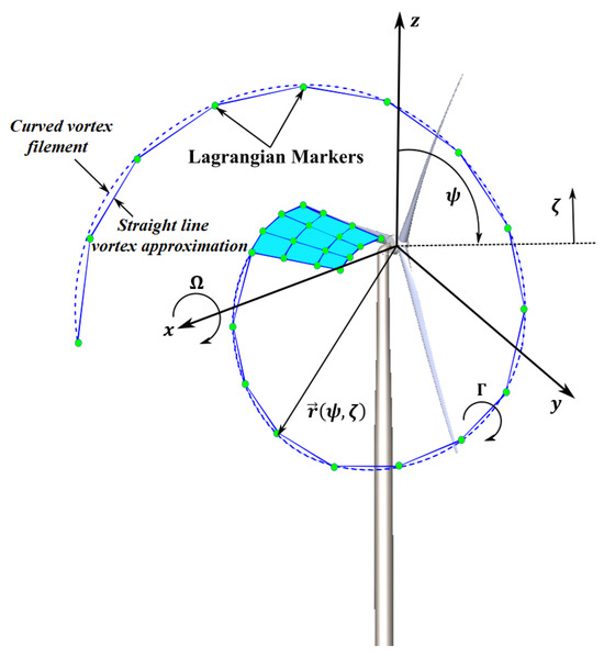
Figure 10.
FVW method explanation.
The vortex-filament motion is expressed as follows [153,156,157,158]:
Here, denotes the positions of the Lagrangian markers and denotes the velocity vector [153,159]. This vector is the summation of three components: the freestream, induced velocity, and velocity emanating from the platform movements due to environmental loading [147,153,159,160]. Each straight-line vortex filament creates an induced velocity at point k, where its calculation is based on the Biot–Savart law [155]:
where is the vortex filament circulation strength, l is the vector used to connect the endpoint locations of filaments, and is the normal distance from l to point k. The factor is used to consider the effect of viscosity on the vortex core [161,162,163]. is obtained regarding the lift force acting on the blade element airfoil using the Kutta–Joukowski theorem [30].
The blade can be represented using either a lifting line or lifting surface [157], or more attractive options such as the Weissinger-L blade model, which has been demonstrated to provide more reliable results than the lifting line model, with a computational cost lower than the lifting-surface model [145,157,158]. Based on a blade model, the circulation along the blade span is computed by discretizing the blade into a finite number of panels, and then the connection to the wake is performed by dependence on the induced velocities.
The FVW is available only in a few simulation tools for the coupled analysis of FWTS, such as QBlade and OpenFAST [58,164]. This method, despite being able to consider the turbine–wake interaction, has not been commonly used in the coupled analyses of FWTS [165].
3.3. Structural Dynamics
Coupled analyses of floating wind turbine systems are performed using a wide range of structural models, from modal analysis methods to more sophisticated finite element methods, such as Euler–Bernoulli and Timoshenko, all based on the following second-order differential equation:
where M, B, and C denote the structural inertia, damping, and stiffness matrices, respectively. Additionally, x is the vector of structural displacements (deformations), and F is the vector of external forces. The structural dynamics are typically considered through the use of an MBD formulation, where the flexibility is considered in selected components, such as blades and towers, as shown schematically in Figure 11. The MBD formulation, the most common approach for the structural dynamic assessment of FWTS, is available in many low- and mid-fidelity simulation tools, such as HAWC2, OpenFAST, SIMA, Bladed, QBlade, Virtual.Lab Motion, and Multibody Bladed [58,166,167,168,169,170,171,172,173].
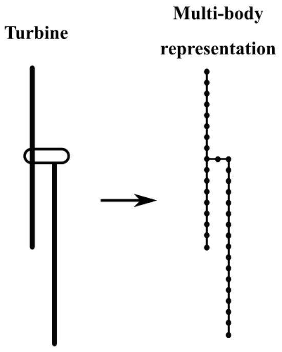
Figure 11.
Multi-body representation of a wind turbine.
In this technique, the geometry of the wind turbine is split into a limited number of interconnected rigid or flexible bodies, which may undergo translational and rotational motions [8]. The connection between the bodies occurs via force and joint elements that express their dynamic and kinematic restrictions. The description of the motion of the bodies is performed through a group of differential-algebraic equations, including the differential equations describing the motion of the bodies and a set of algebraic equations expressing the motion restrictions [41,174]. Among the turbine’s structural elements, the blades normally have the largest number of bodies due to being the most flexible components [41,174].
The long flexible blades and towers are commonly modeled as beam members based on either a linear modal analysis (MA) or more sophisticated beam theories, such as Euler–Bernoulli and Timoshenko [41].
The simplest form of representing the flexible turbine’s structural components is by using the linear MA [30], which is available in many coupled analysis tools for FWTS, such as OpenFAST, Bladed, and QBlade [58,167,168,169,170,175,176,177]. Briefly, in this method, a modal transformation is used to separate the structural responses into various eigenfrequencies, resulting in distinct vibration modes, whose linear superposition gives the total structural response [25,178,179]. Thus, due to its linearity assumption, its use is restricted to small deflections [25]. The flexibility properties of blades and towers, the spanwise mass and stiffness distributions, and their mode shapes based on equivalent polynomial coefficients are defined [179,180]. These mode shapes, where typically only the first few are considered in the modal representation, are commonly determined using a finite element method [180,181]. Therefore, the accuracy of a modal analysis depends highly on the correct determination of the mode shapes, which is a principal disadvantage of this method [30].
However, in the case of large blade deformations, using more advanced beam theories such as Euler–Bernoulli and Timoshenko is preferred over the modal approach [48,182]. For example, using nonlinear beam theories, the OpenFAST from NREL and HAWC2 from the Technical University of Denmark (DTU), can simulate flexible blades. More specifically, OpenFAST employs both theories of the Euler–Bernoulli beam and geometrically exact beam with Legendre-spectral finite elements. The latter can better model the geometric nonlinearities and large blade deformations compared to the former [183], while HAWC2 uses the Timoshenko finite-element modeling approach [184]. The results obtained from these codes are expected to be similar, as shown in [185].
Nonlinear beam theories, by taking geometric nonlinearities into account, mathematically describe how external loads are related to a slender body deflection (based on Equation (10)) through the discretization of the structure into several one-dimensional beam elements. Note that, unlike the Euler–Bernoulli method, the Timoshenko approach considers deformation arising from shear and is, consequently, more suitable for thicker beam elements [31]. On the other hand, in modal analysis, structural deformation is obtained by the linear superposition of a portion of the mode shapes of the structure. Therefore, the use of this method is restricted to small deformations, where the linearity assumption is valid. Furthermore, the predictions given by modal analysis are limited to the modes that are determined and included in the model, and typically, a small portion of geometric nonlinearities can be accounted for.
The floating structure is typically modeled as a rigid body, the same practice adopted in the oil and gas industry. However, accounting for floating platform flexibility can be crucial in the floating wind system design and optimization process, considering the increasing use of large platforms for offshore wind power and the growing tendency to reduce substructure costs.
3.4. Mooring System
A mooring system serves as a station-keeping system for a floating platform. Proper implementation of the mooring system is crucial for keeping the wind turbine nearly fixed in its position, in such a manner, to guarantee the safe operation of the machine.
Generally, there are two types of mooring line systems: catenary and taut, as shown in Figure 12.
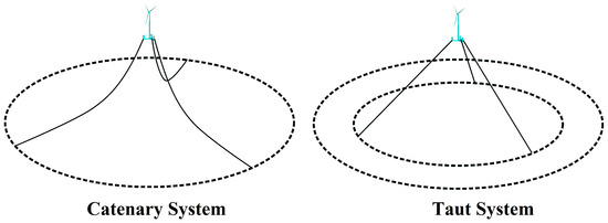
Figure 12.
Mooring line systems: catenary and taut.
In the case of the catenary system, the station-keeping is performed through the weight of the portion of the mooring lines in contact with the seafloor [21,186]. In the case of the taut system, this is performed by the high tension in the cables. In other words, while the mooring line weight provides the restoring force in the catenary mooring system, the elasticity of the mooring line provides this force in the taut mooring system.
Catenary mooring lines are typically made of steel chains and/or wires [187,188], while taut mooring lines are made of synthetic fibers, such as polyester, nylon, or wires [188,189,190,191,192,193]. Recent studies have shown that a taut system composed of nylon may significantly reduce the cost of the floating wind turbine system, especially for shallow water applications, compared to the same system with polyester [189,191].
It is also possible to use a combination of materials for catenary applications (the semi-taut mooring system) to reduce the weight and cost of the mooring system [194]. The chain is typically used to adjust the length and tension of the upper portion, where the mooring line is connected to the floater at the fairlead. Again, the chain is preferred due to its stiffness at the seabed, where the mooring line rests on the sea floor. Synthetic fibers, nylon, or wire can be used for cost and weight reduction. The Hywind project, for instance, uses a combination of steel chain and wire [194].
The catenary configuration is usually applied to the floating platforms at water depths between 100 m and 250 m, where it can be considered an optimum solution for the station-keeping of the system [195]. Based on Figure 13, which shows the cost evolution of a traditional steel chain catenary system regarding water depth, in the case of shallow waters with a depth smaller than 100, the highly dynamic condition in which the floater operates calls for a more expensive station-keeping system [196]. Additionally, the additional mooring line length increases the cost as the water depth exceeds values larger than 250 m.
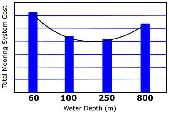
Figure 13.
Cost evolution of a traditional steel chain catenary system regarding water depth (figure generated using data from [195]).
On the other hand, the taut configuration can be used in water depths smaller than 100 m or larger than 250 m [196]. An example of a taut system used at a water depth shallower than 100 m is the Ideol platform installed close to the French coastline at a water depth of nearly 30 m [197].
A floating platform equipped with a catenary system can have some horizontal movement. However, a floating platform with a taut system typically has limited horizontal movement. The disadvantages of the catenary system include its greater seabed disruption and larger footprint. On the other hand, as the anchor experiences relatively fewer loads, the catenary system has more economical anchors. Considering a taut system, the disadvantage is the higher cost of installation and anchoring due to the large horizontal and vertical loads acting on the anchor [27,198]. However, its lower seafloor disruption, smaller footprint, and suitability for shallow and deep waters are the main advantages of a taut system.
In the case of catenary systems, to increase the mooring line tension and, consequently, the restoring force acting on the floating platform, especially in the case of shallow waters, the clump weights can be used, as shown schematically in Figure 14. It is also possible to reduce the mooring line dynamics and weight effects on the platform in the case of deep waters using buoyancy modules, as shown in Figure 14 [199].
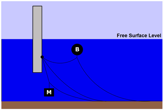
Figure 14.
A catenary mooring system with clump weights and buoyancy modules (M: clump weight, B: buoyancy module).
One main challenge related to floating wind turbines is the high cost of anchoring for a single floating platform. An alternative to reducing these costs is using shared mooring or shared anchoring systems [200,201,202].
However, the use of shared mooring lines is accompanied by several challenges, as follows [203,204]:
- The installation process is more complex.
- The difficulty in towing a single floating wind turbine to a nearby port when it is necessary for operation and maintenance.
- The complexity of a mooring line may increase to a point where it is exposed to failure risk.
- The natural period of several mooring lines may have coupled effects with their surrounding floating wind turbines.
- In the event of a mooring line or anchor failure, this scenario may affect several turbines.
The use of shared anchors is only beneficial under certain situations, calling for a site-specific investigation [204]. Savings from shared anchors can be lost due to the need to increase the length of mooring lines to respect the minimum spacing between turbines, a factor that depends highly on the energy yield calculations of the specific site. Shared anchors are more feasible for sites where it is possible to have smaller turbine spacing [203].
The coupled analysis of a floating wind turbine system is generally accompanied by a mooring line modeling, which is performed using either a quasi-static or dynamic method.
3.4.1. Quasi-Static Method
Quasi-static models can be seen as simple linear stiffness matrices to more complex catenary equations, where Newton’s force equation is solved for each node of connection [205]. These models consider that the mooring is in the balance between the anchor and the FWTS attachment point [30]. Additionally, the dynamic effects, such as inertia, hydrodynamic drag force, and vortex shedding, are not considered [79,94,206,207,208,209].
Figure 15 illustrates how the responses of a mooring line can be affected when dynamic effects are ignored. As can be seen, although the mooring line close to the fairlead tends to follow the floating platform motions, the lower portion of the mooring line may respond with a delay to this displacement. This can be regarded as a violation of the quasi-static assumption, which considers that the line is in static equilibrium at each time step [210].
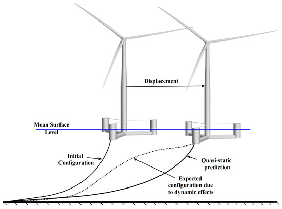
Figure 15.
Possible response of a mooring line under quasi-static and dynamic assumptions.
The quasi-static models tend to underestimate the restoring load, particularly for extreme sea states [48,211,212], and as shown in [213], they are unable to reliably estimate the fairlead load amplitudes.
3.4.2. Dynamic Method
Considering or neglecting the dynamic effects of mooring lines for FWTS is a hot topic in the hydrodynamics of these structures. Due to the smallness of mass and motions, the dynamics may be neglected in the case of mooring systems used in shallow waters. However, it is crucial to consider the dynamic effects of deep water conditions. The oil and gas platform and vessel demonstrate the importance of considering line dynamics for water depths larger than 150 m [92]. Further, using dynamic models is essential for the reliable estimations of ultimate and fatigue loads in a mooring line and the correct modeling of the peak tension in extreme events [30,83].
Dynamic models are better able to simulate real-life conditions, providing the possibility to perform a fully hydro-aero-mooring dynamic analysis of an FWTS. Dynamic models discretize each mooring line into several elements to which separate dynamic equations are applied. These dynamic equations take into account internal forces, including tension, torsion, damping, and bending, which are expressed as functions of the properties of the elements, and external loads, such as gravitational loads and hydrodynamic loads (usually based on the Morison equation).
Therefore, while the quasi-static method assumes that the mooring lines create the restoring loads based on a static equilibrium condition between the anchor and fairlead, the dynamic models consider that the mooring lines are kinematic chains composed of several elements exposed to hydrodynamic loads, as well as interactions with surrounding boundaries. As a consequence, nonlinear effects emanating from dynamic excitation loads are considered in dynamic models.
The main discrepancy between dynamic and quasi-static models originates from the estimation of the magnitude of the tension load, which is usually underpredicted by the quasi-static models, as well as from how the mooring line–environment interaction occurs [30]. This leads to the use of higher safety factors and, consequently, more expensive designs when the quasi-static method is employed. Therefore, to correctly simulate the peak tension, especially in extreme environmental conditions, the use of dynamic models is essential.
One challenge related to the numerical implementation of dynamic models is numerical instability. The best way to control instability is through the use of suitable hydrodynamic and structural damping values, which can confine the transverse oscillation amplitudes [31]. Note that damping values must be chosen carefully in such a way that, while ensuring numerical stability, they do not encourage unrealistic behavior of the mooring lines.
The dynamic models are based on either the lumped mass approach (similar to MBD) [98,107,214,215,216], FEA [94,95,210,217], or the finite difference (FD) method [218]. The hydrodynamic drag and added mass are considered for all the elements resulting from line discretization.
The simplest model is the lumped mass method, where the mooring line model is a set of compact masses connected through massless spring-damper elements [107]. A sensitivity study may be required to determine the number of multibodies beyond which the results remain unchanged. The drawback of this method is that it neglects the mooring line’s torsional stiffness [213,219]. Due to its simplistic nature, the lumped mass method is available in many FWTS simulation tools, such as OpenFAST and OrcaFlex [92].
A higher fidelity solution can be achieved using either the FD or FE methods. However, the results obtained from the lumped mass, FD, and FE methods are expected to be very similar under sufficient resolution [30,213,220].
3.5. Recent Research
Studies carried out on FWTS using nonlinear time-domain models can be subdivided into aero–structural and fully coupled hydro–aero–structural analyses.
The aero–structural analysis is performed either on a fixed wind turbine such as [183], or on a wind turbine under prescribed (harmonic) motions [29,156,159,221,222,223].
In this regard, ref. [183] developed a coupled FVW-geometrically-exact beam theory model to evaluate the aeroelastic behavior of the NREL 5 MW wind turbine.
The aero–structural analysis of FWTS is typically performed under either harmonic platform motions or prescribed time-series motions over single and multiple DOFs estimated from a nonlinear time-domain model such as the OpenFAST code.
Aero–structural analysis of FWTS is typically performed under harmonic platform motions [156,159,221,222,223], or prescribed time series describing platform motions over single and multiple DOFs estimated from a nonlinear time-domain model, such as the OpenFAST code [29].
Accordingly, the aerodynamics of the NREL 5MW FWTS under prescribed motions over single and multiple DOFs is investigated in [29] using an FVW code. The platform motions are estimated using the OpenFAST software. The obtained results demonstrate the importance of using the FVW method to capture complex physics due to the interaction between the rotor and its own shed vortices.
Regarding the prescribed harmonic platform motions, an FVW-MBD coupled model is developed in [156,159] to assess the aeroelastic behavior of the NREL 5 MW wind turbine under harmonic platform motions. Further, an FVW solver is used in [222,223] to evaluate the aerodynamic performance of a rigid FWTS under harmonic surge motions with various amplitudes and frequencies. For tip speed ratios close to the optimum value, it is shown that the turbine power can surpass the Betz limit mainly because of the platform’s axial motions induced on the rotor. Likewise, the aeroelastic analysis of a 15 MW FWTS under the prescribed harmonic pitch and surge motions is performed in [224] using a coupled HAWC2-FVW code, and the results are compared against those obtained from a HAWC2-BEM code. The results highlight a large difference between these codes for high wind speeds.
Many works have been carried out to evaluate the fully coupled hydro–aero–structural behavior of FWTS using nonlinear time-domain models.
For instance, the performances of different codes, such as OpenFAST, Bladed, OrcaFlex, HAWC2, and SESAM, to simulate the dynamics of the semi-submersible floating NREL 5 MW wind turbine are assessed in [11,83] under different load cases. The structural part is modeled using a wide range of methods, from the MBD method to the FEA method. Aerodynamics is represented using mid-fidelity methods, such as the BEM and FVW methods. Hydrodynamic modeling is mainly based on the PF theory with or without the ME. It is shown that the codes based on the Morison approach need to consider the effect of the heave plates as an additional damping force [11,83].
Several works, such as [78,225], demonstrate the importance of considering second-order nonlinear effects when evaluating the coupled dynamics of FWTS. In this context, the 2D harmonic polynomial cell wave tank [226] is used in [78] to calculate linear and nonlinear wave kinematics based on potential flow theory to be used in a coupled analysis for the 5 MW OC4 semi-submersible FWTS [18] based on the HAWC2 code [168,184,227]. The results show the importance of considering a fully nonlinear wave theory for FWTS in shallow and intermediate water depths. Further, the SIMPACK tool based on the ME via a strip theory, the BEM method, and the MBD method is used in [225] to evaluate the dynamics of a 10 MW FWTS. The numerical results are compared against the measurements from a scaled OC4 semi-submersible platform supporting a 1:60 scaled DTU 10 MW wind turbine. A comparison of the calculations and measurements highlights the significance of accounting for the second-order wave effects in the coupled dynamic analysis of the FWTS. Moreover, ref. [100] conducted a coupled analysis of a conceptual 10 MW FWTS using the OpenFAST code. The second-order effects are considered through full QTFs and the Newman approximation. The BEM method is used to model the wind turbine aerodynamics. The results show that using the full QTFs is necessary to model second-order responses accurately. The same conclusion is reached in [228], where the coupled behavior of a 6-MW FWTS at a depth of 100 m is evaluated by using both experimental and numerical methods. The numerical model is developed using OpenFAST. Similarly, the responses of two FWTS (15-MW spar WindCrete [229] and 15-MW ActiveFloat semi-submersible [230], both made of concrete) under static and dynamic conditions are evaluated in [12] using the OpenFAST code. The results show that the second-order wave loads dominate the platforms’ responses more than the first-order wave forces. Likewise, ref. [140] analyzes the low-frequency second-order wave effects on the 5-MW OC4 FWTS using both SIMA (SIMO/RIFLEX/AeroDyn) and OpenFAST codes. In the same vein, the second-order wave effects based on the full QTFs on 10 MW and 5 MW FWTS are evaluated in [100,108] using the OpenFAST code. Another noteworthy study is carried out in [231], where the OpenFAST code is utilized to evaluate the impact of second-order wave hydrodynamic forces based on the full QTF method as well as Newman’s approximation on the time-domain analyses of three FWTS supporting the NREL 5 MW turbine.
Several other works evaluating the coupled dynamics of FWTS are summarized in the following paragraphs:
- The wave–body interaction for an FWTS is simulated in [84] through coupling a hydrodynamic model based on the PF theory and BEM aerodynamic code.
- The performance of two codes, SIMO–RIFLEX and HAWC2, in modeling the coupled dynamic behavior of an FWTS is evaluated in [232]. The structural dynamics and hydrodynamics are modeled in both codes using an MBD method and PF plus ME, respectively.
- A hydrodynamic model based on PF and ME that can account for second-order wave loading is coupled to an aero-servo-elastic model based on the BEM and MBD methods in [233] to predict the responses of the GustoMSC Tri-Floater FWTS.
- The authors of Ref. [234] assess the coupled behavior of a novel catamaran FWTS, where the OpenFAST software is used for the estimation of the aero-elastic part while ANSYS AQWA is utilized to predict the hydrodynamic loads.
- Ref. [235] performs the numerical investigation of the behavior of a 5 MW FWTS through a combination of the PF-based ANSYS-AQWA tool, capable of accounting for second-order loads based on the full QTFs and a BEM code. The flexible blades are modeled using a nonlinear deflection model.
- The dynamic behaviors of four different platforms supporting the NREL 5-MW turbine are compared in [236] against the onshore turbine performance using the OpenFAST code.
- The dynamics of the 5-MW WindFloat FWTS is investigated in [237] using a coupled PF-ME-BEM-MBD code under coupled wave-wind conditions.
- Coupled simulations of a V-shaped semi-submersible FWTS are carried out in [238,239,240] using the coupled PF-BEM-MBD SIMO/RIFLEX/AeroDyn code [241].
- Ref. [242] extends the OpenFAST code to analyze three coupled hydro–aero–structural dynamic behaviors of wind turbines mounted on the same semi-submersible platform.
- The dynamics of a 5-MW braceless steel semi-submersible FWTS is assessed in [243] through coupling a structural model based on beam elements, a first-order PF model, and a BEM method available in the coupled SIMO/RIFLEX/AeroDyn code [244].
- Refs. [83,245] use the OpenFAST software to model the hydro-aero-servo-elastic behavior of the OC5 DeepCwind semi-submersible FWTS, where the full QTFs are used to account for the second-order effects. The same code is also used in [246] to evaluate the coupled behavior of the OC4 DeepCwind semi-submersible FWTS.
- The coupled analysis of a 5-MW–13.2-MW FWTS is performed in [247,248] using a coupled BEM-PF-ME model. The second-order hydrodynamic loads are considered through the full QTFs. The structural responses are modeled using an MBD method with Euler–Bernoulli beams for flexible blades and towers.
- The OpenFAST code is also used in [249] to assess the behavior of a 5-MW V-shaped FWTS in moderate water depths.
- Motions and loads predicted by the open-source OpenFAST and commercial OrcaFlex codes for FWTS are compared together in [250] and it is shown that the predictions provided by these codes are generally in good agreement.
- A coupled numerical model based on BEM-PF-ME is developed in [251] to investigate the dynamic responses of FWTS.
One of the main advantages of nonlinear time-domain models is their ability to simulate mooring system behavior for the FWTS under a variety of operational and extreme conditions. In this regard, the dynamics of the OC4 semi-submersible supporting the NREL 5-MW turbine with a broken mooring line is simulated in [252] using the OpenFAST code. Ref. [253] tests different mooring configurations for a 5-MW FWTS using the OpenFAST code. The behavior of the OC4 DeepCwind semi-submersible FWTS with a mooring line failure is assessed in [217] by coupling the BEM aerodynamic model available in the OpenFAST software to ANSYS-AQWA, which is responsible for the computation of the hydrodynamic loads. The responses of the drive train are also considered through a multibody drive train model using SIMPACK [254]. The dynamics of the OC4 FWTS after one of its mooring lines is broken is assessed in [255] using both ANSYS-AQWA and OrcaFlex software. Ref. [256] analyzes the coupled behavior of a 5-MW FWTS, where the aero-servo-elastic part of the OpenFAST code is coupled to ANSYS-AQWA, and is capable of modeling nonlinear hydrodynamics and mooring line behavior.
As mentioned previously, time-domain simulations are predominantly performed by considering a rigid floating platform rather than a flexible one. Accordingly, the impact of platform hydroelastic deformations on the dynamic responses of a 20 MW FWTS is assessed in [257], using the nonlinear aero-hydro-servo-elastic code ‘SIMA’, which is a combination of RIFLEX and SIMO software. RIFLEX is responsible for structural analysis based on a nonlinear beam theory approach, which here models the platform, tower, and turbine blades. The hydro-aerodynamic loads are computed from a coupled BEM-PF-ME with the difference-frequency second-order loads. The results confirm the need to take hydroelastic deformations into account in coupled dynamic analysis for large floating wind turbines, especially in extreme conditions.
Another notable study is carried out in [258], where the OpenFAST code is used to evaluate the impact of the motions of two types of floating platforms, e.g., OC3-UMaine spar and OC4-DeepCwind semi-submersible, on the power generation of the NREL 5 MW turbine subjected to irregular waves and various wind conditions imported from the LES code SOWFA from NREL [259].
4. High-Fidelity Models
4.1. Hydrodynamic and Aerodynamic Modeling Based on Computational Fluid Dynamics
The fluid dynamics around FWTS can be most accurately captured by solving the NSE based on CFD [260]. The NSE, in the case of incompressible Newtonian fluids for Cartesian coordinates, is as follows:
Here, variables and P denote the instantaneous velocity components and pressure, which vary over time (t) and space . is the instantaneous strain rate tensor. Note that in the case of wind turbine simulations, several new terms may be added to the NSE to consider the effects of Coriolis and buoyancy forces [261,262].
To compute the pressure and velocity fields, the NSE is solved together with the continuity equation, as follows:
A reliable aerodynamic evaluation of the FWTS depends on the accurate turbulence modeling around these machines [263]. In this regard, in the case of turbulent flows, CFD solves the NSE using three different approaches: direct numerical simulation (DNS), LES, and (unsteady) RANS equations. An adequately formulated DNS captures all the relevant turbulence scales up to the Kolmogorov scale using an extremely refined grid [264], which is not viable due to being prohibitively expensive. Therefore, LES and RANS are used to partially or entirely model the turbulence effect on the flow [265].
The important energetic large eddies are captured by LES, while the influences of the smaller eddies, whose properties are more universal, are parameterized based on a subgrid-scale (SGS) model [265]. A spatial filtering operation is used by LES to divide the scales into large eddies constituting the resolved scales and small eddies representing the unresolved scales [260,266]. Applying this filtering operation transforms the NSE as follows:
Here, the variables and are the filtered velocity components and pressure. Additionally, is the tensor of strain rate, defined as a function of the resolved velocity components. The new term is the tensor of SGS Reynolds stress that emerges in the NSE due to spatial filtering. Through this term, the influence of the unresolved smaller eddies is parameterized. The most common approach to compute is the Smagorinsky model [267,268]:
where is the eddy viscosity, which is characterized in terms of the resolved velocity field [269]. However, this model is unable to account for the turbulence anisotropy and secondary flows due to the use of the Boussinesq hypothesis [264,270,271]. To overcome these limitations, several other SGS turbulence models are proposed, such as scale-dependent dynamic, anisotropic minimum dissipation, dynamic Smagorinsky, and mixed SGS [272,273,274,275].
However, the LES requirement of grid refinement in three directions close to a solid wall to compute the turbulent boundary layer makes applying LES to the turbine blades infeasible. Thus, LES is generally used for simulating turbine wakes where the turbine rotor is parameterized using actuator methods, including the actuator disk, actuator line, and actuator surface, as shown schematically in Figure 16 [276,277,278,279,280]. Using actuator methods leads to a drastic drop in computational costs due to eliminating the need for resolving the boundary layer close to the blades. Another way to decrease the computational demand of LES is to utilize hybrid RANS-LES methods, in which RANS equations are used for modeling the boundary layer close to the body, while LES is employed over the separated unsteady region far from the body [174,281,282,283].
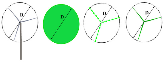
Figure 16.
From left to right: wind turbine geometry, actuator disk, actuator line, and actuator surface [280].
The simulations based on RANS equations constitute the most popular approaches for the aerodynamic evaluation of turbines based on CFD methods [284,285]. Similarly, hydrodynamic loads acting on FWTS are most commonly calculated using RANS equations with a turbulence model, which are solved numerically using the finite volume method [8,79,206,207,260,286,287].
The RANS equations, which are the result of ensemble averaging of the Navier–Stokes equations (NSE), are written as follows [206,207,288]:
Here, the variables and p denote the ensemble mean velocity components and pressure, which may vary over time, t, and space . Additionally, , , and are the fluid density, fluid kinematic viscosity, and mean strain rate tensor, respectively.
The term is called the Reynolds stress tensor representing the turbulence effect. This term is most commonly modeled using eddy viscosity (EV) models based on the Boussinesq hypothesis [289]:
where k is the turbulence kinetic energy, is the Kronecker delta function, and is the EV. In the simplest way, the EV can be determined without solving any further transport equations, e.g., the mixing-length model of Prandtl [290,291]. Later, more sophisticated one-equation and two-equation turbulence models are developed to compute directly or indirectly the EV [79,88,207,208,286,292]. The most popular models for the hydrodynamic evaluation of FWTS are the two-equation models, such as k-ε, k-ω, and k-ω shear stress transport (SST) [63,79,287,292,293], in which by solving two transport equations the turbulence is modeled. This is again true for the aerodynamic evaluation of an FWTS, where the most popular models are the two-equation models, especially k-ω and k-ω SST [294,295,296,297,298,299,300,301]. Nevertheless, due to the use of the Boussinesq hypothesis, these models are incapable of considering the turbulence anisotropy [270,271,302,303,304]. Thus, more sophisticated models such as realizable models [305,306], Reynolds stress turbulence (RST) models, and nonlinear EV models are recommended, especially for the accurate prediction of aerodynamic loads [270,271,307,308,309,310]. The RST models, in which each Reynolds stress term is computed from a separate transport equation, provide the most accurate results at the cost of higher computational demand [270,271,309,311]. An alternative is the use of nonlinear quadratic and cubic EV models, which can account for the turbulence anisotropy at a much lower computational cost. It is worth mentioning that—to diminish the computational demand—the use of actuator methods to represent the turbine rotor is also common in the RANS context [312].
To model the free surface, CFD uses two main approaches: interface tracking and interface capturing [313,314] (see Figure 17).
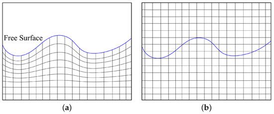
Figure 17.
Free surface modeling in CFD. (a) Interface-tracking approach; (b) interface-capturing approach.
The interface-tracking method, as its name implies, tracks the free surface by implementing a Lagrangian grid fitted to the free surface interface (see Figure 17a). Nevertheless, tracking the free surface where this interface experiences large motions imposes certain difficulties, which can only be remedied by remeshing techniques. Using this technique—in addition to increasing the computational demand—can introduce errors in the numerical solutions.
Nonetheless, the interface-capturing method, which is also called the Eulerian grid method, as its name implies, captures the free surface interface by computing a volume inside a computational domain encompassing the free surface. Contrary to the interface-tracking method, the grid does not track the free surface evolution over time (see Figure 17b).
The free surface modeling in the case of FWTS is most commonly performed using the volume of fluid (VOF) and the level set, with both belonging to the interface-capturing methods [41,63,79,88,206,209,275,286,292,293,315,316,317].
To capture the free surface profile using the interface-capturing method an increased cell density is required to be close to the free surface. The common approach is to employ a certain number of cells perpendicular and normal to the free surface for spatial discretization [318]. The increased cell density on the free surface can also be achieved based on the kinetic wave energy [292,319].
Two methods exist to ensure that no wave reflection will occur on the boundaries of the numerical domain. The first method involves dampening the waves by coarsening the grid toward the boundaries [287,318]. Another method involves using a damping (relaxation) function over a damping (relaxation) zone close to the boundaries to force the wave field toward the undisturbed free surface or wave [206,209,286,292,320].
4.2. Structural Dynamics
The FEA method is usually applied to model the structural responses, but it is also used for fluid dynamics [321].
The FEA, similar to CFD, uses the blade’s exact geometry and is based on a methodology similar to other numerical methods, approximating continuous governing partial differential equations with a set of algebraic equations [322].
The governing equation is obtained by assuming that the amount of virtual work performed by external loads equals the amount of virtual work absorbed by dissipation, inertia, and internal forces [30]. The governing equation form is depicted as a set of second-order differential equations, as follows:
Here, M is the matrix of element mass, B is the matrix of element damping, x is the vector of structural displacement, is the vector of internal reaction loads, and is the vector of external forces. Note that in the case of materials with linear elasticity, is related linearly to x through a matrix of stiffness.
In the first step, the turbine geometry is discretized into a finite number of elements. These elements are typically triangles, quadrilaterals, tetrahedra, and hexahedra. The blades are typically discretized into 3D composite shell elements [25,323].
In each element, the displacement values at the element nodes are used to construct the distribution of this variable within the element [324]. Note that the stresses and strains, which are also of interest, are expressed in terms of nodal values of displacements based on Cauchy relations and Hook’s law [325]. Based on local distributions of the displacement, shape functions, usually based on polynomial forms, are used to interpolate the displacement values to any other point inside the element. The global system of algebraic equations is obtained by assembling all the element equations. This system of algebraic equations is solved using direct or iterative methods to obtain the nodal values of the displacements.
4.3. Recent Research
The coupled CFD-FEA method provides an intriguing option for investigating hydro–aero–structural dynamics of an FWTS under coupled loading due to its high accuracy and minimum level of parametrization. However, this method is rarely used to evaluate the hydro–aero–structural dynamics of these structures due to its high computational demand. Ref. [317] carries out an example of these types of studies to evaluate the fluid–structure interaction for the NREL 5 MW supported by the OC3-Hywind SPAR floater [169], where the free surface is modeled using the NSE with the level set method. Additionally, the FEA is used to discretize the fluid dynamic-governing equations, and the FWTS structural dynamics are modeled based on an isogeometric analysis. However, the developed coupled model is only applied to the parked configuration of the wind turbine. Thus, considering the prohibitively high computational cost of a coupled CFD-FEA method, the researchers have reduced the coupled analyses of FWTS to aerodynamic analysis under prescribed platform motions, aeroelastic and hydro-aerodynamic analyses.
4.3.1. Aerodynamic Analysis under Prescribed Platform Motions
In these analyses, to reduce the computational cost, the hydrodynamic part is simplified to focus on the aerodynamic part. Therefore, the harmonic motion will be prescribed on the platform in a predetermined degree of freedom (DOF) of motion to emulate the reaction of oscillating wave loads on FWTS.
Several studies have been performed in the literature to evaluate the aerodynamics of a wind turbine (predominantly the NREL 5-MW model [19]) under harmonic motion in surge and/or pitch and/or yaw direction(s) using a CFD code based on URANS equations [46,75,143,221,326,327,328,329]. The turbulence modeling is mainly carried out using the two-equation k-ω SST model, except for [221,326,329], where the k-ω Kok turbulence model, no turbulence model, and the realizable k-ε model, respectively, are employed. Furthermore, to model the turbine rotor, some studies, such as [326,329] choose to use an actuator line (AL) method rather than modeling it directly in the CFD simulation.
In the AL method, the aerodynamic loads acting on the turbine blades are calculated using the angle of attack of the flow incident on each two-dimensional airfoil element along the blades, plus the tabular aerodynamic data of the airfoils. Furthermore, a 3D Gaussian correction method is used to ensure that the aerodynamic loads acting on the blades have a smooth distribution over the mesh cells, without any singular behavior [326,329]. Additionally, among studies where rotor geometry is simulated directly, only Ref. [143] specifies the modeling approach for the turbulent boundary layer adjacent to the blade surface, using wall functions. In other studies of this type, no information is provided on how the turbulent flow near the turbine blades is captured [46,221,327]; although some studies mention the size of the thickness of the first prismatic layer adjacent to the blade surface [75,328].
To simulate the platform and rotor angular motions, several methods are used. In this regard, the unsteady motions of the platform are modeled using an overset grid in [46,221,326,327,328]. The platform motion is modeled using a different approach based on a dynamic mesh technique in Refs. [75,143]. As shown in [75], for large platform motions in which the grid is highly deformed, leading to a low-quality mesh, the utilization of a remeshing method is necessary to regenerate the mesh in locals with low quality, based on criteria capable of assessing the mesh quality, such as cell volume and skewness. The rotor rotational motion is simulated either using the moving reference frame approach [46,75,143] or a sliding mesh technique [143,328]. In the moving reference frame approach, the grid remains stationary, and no physical motion is modeled. Moreover, the authors in [327] apply an optimization technique to the overlapping area of the overset mesh between the background stationary grid and the moving part to increase the accuracy of interpolation between these two areas.
Generally, the results obtained from these studies demonstrate the significant impact of harmonic motions, especially in pitch and surge directions, of the platform on the turbine aerodynamics. This is mainly due to the interaction between the rotor and its shed vortices, which certainly affects the aerodynamics of the machine. Furthermore, comparing the CFD results with the results obtained from the OpenFAST code, as performed in [221], demonstrates the importance of CFD for the accurate prediction of complex unsteady aerodynamics in FWTS.
A few works have also evaluated the platform motions under prescribed aerodynamic loads. For instance, the hydrodynamics of an FWTS is evaluated in [287] for various wind–wave conditions using RANS equations with the k-ω SST model without the turbine presence. The corresponding aerodynamic loads for each wind speed are exerted at the center of rotation of the platform.
4.3.2. Aeroelastic Simulations
Although both aerodynamic and hydrodynamic loads impact the elastic deformations of the FWTS structure, considering the high costs of coupled CFD-FEA studies, such studies are mainly restricted to aeroelastic investigations, where the interactions between aerodynamic loads and blade structural dynamics are assessed. This is because the larger and more flexible modern wind turbine blades typically have lower flexural rigidity, provoking more intensified coupled aero–structural dynamics, which accentuates the importance of the aeroelastic evaluation of these large machines [109,146,284,330,331,332]. In these simulations, the blades are typically discretized into 3D composite shell elements [25,333,334].
Ref. [331] investigates the wind gust effect on the structural responses of a large-scale turbine through coupling a CFD solver based on RANS equations with the k-ε model and an FEA code based on shell elements.
The performance of geometrically adaptive blades on the NREL 5MW turbine in mitigating the destructive effects of the typhoon is tested in [335] through a coupled FEA-CFD method. The blade discretization in the FEA is performed using 3D composite shell elements, and the flow field in the CFD code is modeled using unsteady RANS equations with the k-ω SST model.
4.3.3. Hydro-Aerodynamic Simulations
Coupled hydro-aerodynamic CFD models are developed in [209,293,336,337,338,339,340,341] to evaluate the dynamics of the reference OC4 semi-submersible platform supporting the NREL 5-MW wind turbine under different wind and wave conditions. The CFD models are predominantly based on URANS equations coupled with the k-ω SST model. Again, except for [337,338], where the wind turbine blades are modeled using an AL technique, the turbine rotor geometry is modeled directly in most of these works.
The most important results obtained from these studies can be summarized as follows:
- 1.
- The platform motion is shown to be responsible for a 10% decrease in the mean turbine power production [340].
- 2.
- Comparing the results with those obtained from the OpenFAST code indicates the importance of using nonlinear models with increased wave steepness [293].
4.3.4. Final Remarks on High-Fidelity Models
As inferred from the previous sections, most of the coupled analyses of FWTS are performed within a CFD code to assess the hydro-aerodynamic behavior of the system, except for the aeroelastic simulations, which are carried out through coupled CFD-FEA simulations. This may be associated with most of these studies adopting a 5 MW wind turbine in which the structural deformations have little impact on the whole system dynamics.
In this regard, as shown in Figure 18, the most popular CFD software used in the coupled simulations of FWTS is the open-source CFD code OpenFOAM, followed by the commercial CFD software STAR-CCM+. The number of papers involved in this statistical analysis is 23.
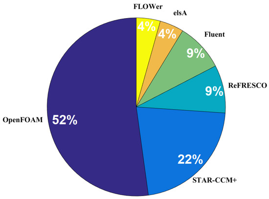
Figure 18.
Percentage of CFD software used to study the coupled behavior of an FWTS.
By considering both viscous effects and detailed FWTS geometry, CFD can simulate the FWTS dynamic responses more realistically. To accurately predict the loads and dynamic responses of an FWTS based on CFD, the correct reproduction of the environmental conditions, including the atmospheric boundary layer (ABL), is critical. In the case of LES, the most reliable approach for generating a realistic inflow condition is using a precursor method, where the ABL is simulated in a separate numerical domain without the turbine’s presence. The resultant wind flow field is then utilized as the inflow condition to a second domain, which encompasses the turbine geometry [342,343,344]. In the case of RANS simulations of turbines, the wind profile must remain homogeneous in the horizontal direction as it propagates toward the body. This is typically guaranteed through a proper combination of the boundary conditions and the addition of new source terms into the momentum equations [345,346,347,348,349].
Another critical issue regarding the CFD simulations is the choice of an adequate turbulence model. The coupled simulations of FWTS are consistently performed using RANS equations. As shown in Figure 19, the most popular RANS turbulence model used in these simulations is the k-ω SST model, followed by the Spalart–Allmaras model, where both are based on the Boussinesq approximation, ignoring the turbulence anisotropy. The number of papers involved in this statistical analysis is 22. However, one can use nonlinear eddy viscosity models, which offer better accuracy in capturing the turbulent flow characteristics while maintaining the computational cost to an acceptable level.
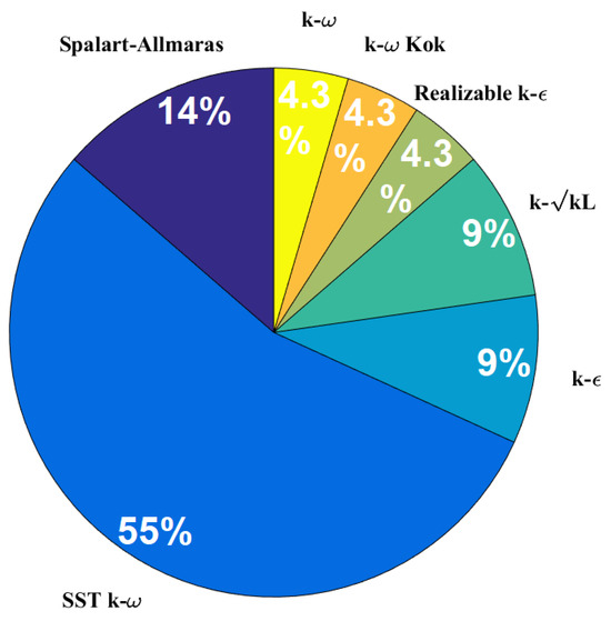
Figure 19.
Percentage of turbulence models used in CFD codes.
Another important issue that has not been evaluated sufficiently is the accurate representation of the turbulent boundary layer near the FWTS body in the coupled simulations of these structures. For this purpose, a highly refined grid with a y+ value smaller than 5 is usually required. However, this may lead to a large number of mesh cells, which significantly increases the computational cost. Therefore, an alternative is to use wall functions together with a relatively coarse grid with a y+ value from 30 to 100 to model the turbulent flow behavior within the boundary layer. Based on the review carried out here, little attention has been paid to this topic in the studies on FWTS. In a majority of coupled CFD simulations of FWTS, such as in [46,221,287,327,328,336], it is not clear how the turbulent boundary layer close to the FWTS is treated. As shown in Figure 20, a considerable percentage of coupled CFD simulations of FWTS avoid capturing the turbulent boundary layer close to the rotor blades by using an actuator method, such as the actuator line [337,338]. Additionally, several works have used wall functions (WFs) [209,331], and a few works have resolved the boundary layer down to the viscous sublayer by adopting a grid with a y+ less than 1 [330,340]. The number of papers involved in this statistical analysis is 13.
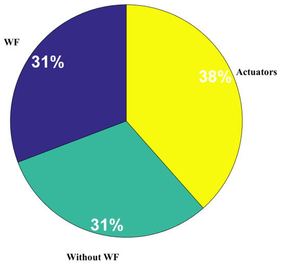
Figure 20.
Percentage of methods used to model the turbulent boundary layer close to the blades: wall function (WF), without WF, and actuator methods.
In this regard, one of the few studies that assess the impact of near-wall grid resolution on CFD simulations of FWTS is carried out in [143], where the effect of different values of y+ ranging from 10 to 100 on the aerodynamic performance of the NREL 5 MW reference wind turbine is evaluated. In this work, the k-ω SST turbulence model (with wall functions) is used to represent the effect of turbulence. The results indicate that the best predictions are obtained with y+ around 30, which makes sense since the y+ values used here coincide with the buffer and log-law sublayers of the boundary layer, and as well-known, the wall functions work well when applied to the log-law region.
Moreover, the coupled analyses of FWTS are restricted to regular wave conditions, where the system behavior is investigated under several monochromatic wave conditions. In other words, simulations of realistic irregular sea states are not common due mainly to a high computational cost emanating from the requirement of a relatively long simulation physical time, which is usually up to 3 h to capture all the necessary nonlinear and low-frequency effects [350]. This kind of simulation has become more common very recently, especially for assessing floater behavior in real sea states, where the irregular sea is generated by a low-order model typically based on the nonlinear PF theory and then imported to a CFD model using a one-way coupling scheme. This allows for the reduction of the CFD domains, reducing the computational demand [350,351].
Finally, it is worthwhile to mention that to capture the transient motions of the moving part of an FWTS, several methods, such as the moving reference frame, sliding mesh, and overset methods, are used [46,75,79,135,143,208,209].
5. Final Notes on Numerical Models
Table 1 summarizes the tools used to perform the coupled hydro–aero–structural analysis of floating wind turbines based on low- and mid-fidelity codes.

Table 1.
Summary of the capabilities of coupled numerical tools.
As can be inferred, most of these tools use the BEM method with various corrections to compute the aerodynamic loads. The main difference between the BEM, GDW, and FVW methods is their consideration of the dynamic inflow condition. A correction referred to as a dynamic inflow model is typically used within the BEM method for the better representation of the aerodynamic responses under unsteady conditions emanating from changes in the inflow wind speed, rotor speed, and blade pitch angle, as well as platform motions. However, the dynamic inflow is directly considered by the GDW method. A limitation of the GDW method is the assumption of the smallness of the induced velocities compared to the free flow, which creates instability at low wind speeds. Finally, the FVW method can account for the dynamic inflow due to its basic formulation.
In this regard, the offshore code comparison collaboration (OC6) evaluates the validation of 54 aerodynamic numerical models for a floating wind turbine subject to large harmonic support platform motions in both surge and pitch directions [352]. The validation uses wind tunnel measurements from a 1:75 scaled DTU 10 MW wind turbine. A wide range of modeling approaches, such as BEM, dynamic BEM (DBEM) (which considers the effects of dynamic inflow), GDW, FVW, and blade-resolved/actuator-line-based CFD methods, are evaluated. The tests are performed at a wind speed of 4.19 m/s and an angular velocity of the rotor of 240 rpm, equivalent to the scaled model’s rated condition. The measured and calculated torque moment and thrust force of the turbine during one harmonic surge motion of the platform with a frequency of 1 Hz and an amplitude of 0.035 of the rotor diameter are presented in Figure 21. Note that the numerical results are median values for each modeling technique.
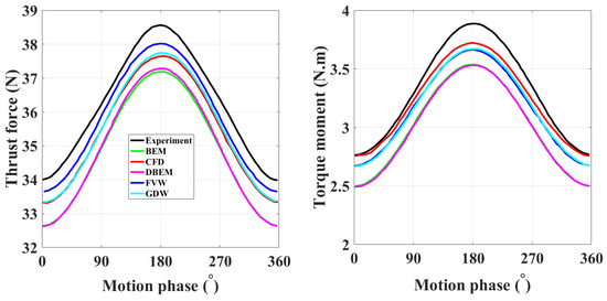
Figure 21.
The measured and calculated (using a wide range of modeling approaches, such as BEM, DBEM, GDW, FVW, and CFD) torque moment and thrust force of a scaled turbine model during one harmonic surge motion of the platform with a frequency of 1 Hz and an amplitude of 0.035 of the rotor diameter (figure reproduced using the data given in [352]).
As can be inferred, the predictions provided by the FVW method are comparable to those provided by the CFD and even better in the case of thrust force. The poorest predictions are produced consistently by the BEM and DBEM methods.
Note that the CFD results presented in Figure 21 are based on both the AL method and blade-resolved simulations. Considering the high speed and high frequency of the platform motions, the flow field around the blades is extremely complex and unstable, giving rise to several unstable phenomena, such as unsteady flow, localized dynamic stall, variations in the magnitude of the local velocity of the blade section, and the angle of attack. CFD simulations based on the AL method may require additional corrections and optimizations to accurately capture the aerodynamic performance of the FWTS and most AL methods may not consider hub and nacelle geometry. Therefore, the CFD predictions shown in Figure 21 may be affected by the shortcomings of AL methods in dealing with the complex flow field emanating from harmonic platform motions.
Regarding the hydrodynamics, as shown in Table 1, either the Morison equation or potential flow theory—or a combination of both—is employed. Second-order potential flow theory based on the QTFs is employed to account for the fundamental second-order effects. It is crucial to consider these effects because a moored floating platform, unlike an unrestricted platform, has natural frequencies in the horizontal plane, generally outside the frequency range of the incident waves. The natural frequencies in the horizontal plane are excited by the low second-order frequencies emanating from the second-order potential problem. As shown in the OC5 Phase II validation project [83], underestimating low-frequency loads can lead to a 20% underestimation of the loads and motions of a floating structure. This underestimation remarkably affects the correct estimation of the fatigue and ultimate loads acting on the floating structure.
As suggested in the project of the OC6 Phase I, improvement in the low-frequency predictions can be achieved by tuning the QTFs using data from physical tests or high-fidelity CFD simulations [118].
Accordingly, a RANS-based CFD model, together with the VOF method, is used in [63] to fine-tune the QTFs of an FWTS obtained from the potential flow theory for a group of bichromatic regular waves, with a frequency difference corresponding to the natural frequency of the FWTS in the surge or pitch direction. In this regard, Figure 22 shows the phases and magnitudes of the QTFs related to the force in the surge direction and the moment in the pitch direction obtained from CFD (the new QTF) using the open-source finite volume code ‘OpenFOAM’, and the potential flow theory (the old QTF) using the commercial code ‘WAMIT’. As can be seen, a considerable difference exists between the predictions; regarding the QTFs related to the force and moment magnitudes, this difference increases even more at higher frequencies, while regarding the phase, there is consistently a significant difference in predictions, with CFD showing nearly opposite trends for the phase angle compared to potential flow theory.
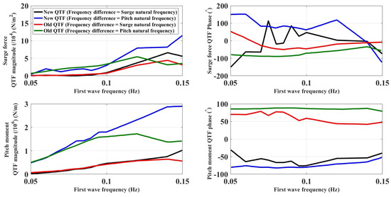
Figure 22.
Phases and magnitudes of the QTFs related to force in surge direction and moment in pitch direction obtained from both CFD and potential flow theory using the commercial code WAMIT (Figure reproduced using the data given in [63]).
Note that to accurately predict the oscillatory motions of a moored floating structure, in addition to QTFs, the potential flow solver requires the inclusion of a quadratic damping coefficient (present in the Morison equation) obtained from physical tests or CFD simulations. Understanding mooring-induced damping and low-frequency motions is important, particularly in irregular waves and during significant translations of moored structures [353].
The frequency-dependent characteristics of a floating platform are most commonly obtained by using either AQWA [87,98,107,108,114] or WAMIT [113], as shown in [107]. Generally, a good agreement exists between the two codes. AQWA can perform the time-domain simulations [87,98]. However, one needs to specify how the aerodynamic loads are computed. These loads can be calculated using simple expressions within the software or through coupling with other codes such as OpenFAST.
As seen in Table 1, the structural flexibility is accounted for through an MBD formulation, where flexibility is considered by either a modal method or finite element representation. The flexibility is generally applied to the wind turbines, and substructures are typically assumed to be rigid.
Finally, several suggestions are provided here regarding the determination of the numerical models:
- Mooring line modeling based on quasi-static methods is suitable for frequency-domain analysis of floating wind turbines, where the steady-state responses of the systems are evaluated. In the case of time-domain analysis, better accuracy, especially in estimating ultimate and fatigue loads and modeling peak tension in extreme events, is achieved using dynamic models.
- In structural dynamic modeling, the use of the modal analysis approach should be avoided in large blade deformations; instead, more advanced beam theories, such as Euler–Bernoulli and Timoshenko, are preferable. These advanced beam theories can also be used to consider the hydroelasticity effects of the floating structures, which are typically assumed to be rigid.
- Caution must be taken when using QTFs in determining the second-order hydrodynamic loads acting on FWTS using PF solvers, as it may be necessary to use wave basin tests or high-fidelity simulations to tune the QTFs obtained.
- Although the BEM theory constitutes the most popular method for aerodynamic assessment of wind turbines, in the case of FWTS, one may consider using the FVW method, which takes into account the evolution of the wake of a wind turbine over time. This is a significant feature as FWTS are subject to interactions with their own wake due to platform motions.
- High-fidelity methods, especially CFD simulations, are an indispensable part of the dynamic analysis of floating wind turbines. These simulations, in addition to being used to tune the QTFs, are excellent in deriving and calibrating the coefficients present in the Morison equation. However, more caution must be taken when creating a CFD simulation, especially in choosing a turbulence model that should be capable of correctly considering the effects of turbulence anisotropy, as well as a suitable method to accurately resolve the turbulent boundary layer close to the FWTS body.
Note that in addition to the coupled numerical models presented so far, the coupled dynamic analysis of FWTS may be carried out through other coupling schemes, as follows:
- Coupled CFD-MBD models [41,174,208,330,354,355,356]:
An aeroelastic model is developed in [354] by combining the CFD-based AL method with a beam solver to evaluate the coupled aero–structural responses of the NREL 5 MW wind turbine in both the isolation and wakefield of an upstream wind turbine. It was shown that considering aeroelastic deformations leads to the aggravation of the tower shadow effect.
A CFD solver based on URANS equations with a k-ω model coupled with an FEA code based on non-linear Timoshenko beam elements is used in [330] to investigate the aeroelastic behavior of the reference 10 MW DTU wind turbine at various uniform wind speeds [355].
Ref. [356] evaluates the NREL 5 MW wind turbine’s aeroelastic behavior by coupling a URANS-based CFD model with a geometrically exact beam formulation’s FEA code under harmonic platform surge motions. The turbulence model in CFD is the k-ω SST model. Ref. [174] proposes an aero-elastic model that considers the drive train dynamics by coupling the hybrid RANS-LES CFD model responsible for the flow field prediction with an MBD. The model is applied to the NREL 5 MW wind turbine to investigate the interaction between turbine aerodynamics, flexible blades, and drive train dynamics.
A coupled hydro-aero-elastic model is developed in [208] to simulate the OC4 semi-submersible FOWT under a combined wind/wave operating condition. The hydrodynamic model is based on RANS with the k-ω SST model and VOF method, and the structural model is based on an MBD.
An overset grid CFD solver based on the DDES model derived from the k-ω SST coupled with an MBD solver is used in [41] to predict the aeroelastic behavior of the floating NREL 5 MW wind turbine subject to an ABL. Blades and towers are considered flexible one-dimensional structures.
- Coupled CFD-BEM-MBD models [357]:
A CFD model, which is responsible for the platform hydrodynamics, is coupled to the aero-servo-elastic OpenFAST code in [357] to simulate the OC4 DeepCwind FOWT dynamic responses under various operating conditions. More accurate results are obtained using this coupled tool compared to the OpenFAST simulations alone.
- Coupled CFD-PF models [275]:
Ref. [275] proposes a coupled fluid–structure interaction model based on LES to study FWTS motions in waves. The domain is divided into two parts: near-field, where a two-phase LES solver based on the level set method is used, and a far-field model, where an aerodynamic model based on LES without viscosity is combined with a hydrodynamic model based on a fully nonlinear potential flow theory. The modeling of the subgrid-scale turbulence over the near-field region is performed using the dynamic Smagorinsky model, while the scale-dependent Lagrangian dynamic model is used over the far-field region.
- Coupled CFD-PF-MBD models [358,359]:
The wakefield of the OC4 semi-submersible FWTS is compared against its fixed-bottom counterpart under ABL conditions in [358]. The wind turbine rotors are represented using an AL method based on the OpenFAST code, where the wind flow is simulated using the SOWFA LES solver from NREL, with the standard Smagorinsky model responsible for subgrid-scale turbulence modeling [359]. The results indicate a small deviation between the wake patterns of the FWTS and its fixed-bottom counterpart.
- Coupled PF-FEA models [360,361]:
Ref. [360] analyzes the ship-FWTS collision using a coupled linear PF-FEA model. The aerodynamic thrust force is considered to be a point load acting at the hub based on the thrust curve of the 5 MW NREL wind turbine. The linear diffraction theory and an FEA model are combined in [361] to evaluate the hydro-elastic behavior of a novel triangular floating platform capable of accommodating three wind turbines on its vertices.
6. Physical Testing
The importance of physical tests is twofold. First, they are crucial for the validation of the numerical models presented in the previous sections. Additionally, they sometimes enhance our understanding of the physical aspect of the problem by revealing the complex phenomena that may only be recognized using physical modeling techniques. This enhanced understanding eventually leads to an improvement in the low- and mid-fidelity numerical models.
6.1. Lab Testing
6.1.1. Full Physical Testing
The main challenge of performing the full physical experiments is the need to address the Reynolds scaling problem of the Froude-scaled FWTS model in such a manner as to decrease the scale effects during the tests [8,48,65,301,362,363]. This is because satisfying—at the same time—both platform Froude-number scaling and turbine Reynolds-number scaling is impossible [48,363,364]. The lower Reynolds number of the Froude-scaled FWTS model leads to a misrepresentation of the aerodynamic loads in a Froude-scaled environment, which, consequently, leads to a dissimilar dynamic response between the model and the prototype [301,363,364,365]. To solve this issue, several solutions are proposed to diminish the difference between the thrust coefficients of the model and the prototype, which is shown to impact the FWTS responses significantly [366]. The most popular solutions are as follows:
- 1.
- Using a mechanical pulley system [367].
- 2.
- Applying an increased wind speed to the Froude-scaled FWTS model [48,368,369].
- 3.
- Redesigning the blades’ geometry [83,366,370,371,372,373,374]
- 4.
- Implementing an active control for blade pitch on the Froude-scaled model [233,375,376,377,378].
In this regard, a 1:47 Froude-scaled FWTS model is tested in [379,380] to validate the results of the dynamic responses of its equivalent prototype obtained from a coupled SIMO/RIFLEX/HAWC2 code. A rotor pitch control system is implemented to ensure that the FWTS model has dynamic behavior similar to its prototype. In Ref. [366], the authors design a scaled-down NREL 5 MW wind turbine model to obtain a thrust coefficient similar to that of the full-scale wind turbine prototype, ensuring similarity between the dynamic behavior of the model and the prototype when subjected to Froude-scaled wind–wave operating conditions. In Ref. [233], the authors implement an active blade pitch control in a 1:50 Froude-scaled model of the GustoMSC Tri-Floater FWTS, where the NREL 5 MW wind turbine is used. The results show the potential of the active blade pitch control to reproduce an improved level of thrust force.
Through testing on the DeepCwind-OC5 floating platform supporting a 1:50 scale NREL 5 MW turbine, it is demonstrated in [375] that implementing an active blade pitch control in a suitably scaled wind field based on the Froude number—together with a turbine model with a thrust coefficient similar to the full-scale prototype—can result in a model that is capable of reproducing the motions of the full-scale FWTS. Ref. [381] carried out tests on a 1:50 Froude-scaled OC4 semi-submersible FWTS model with two different blade designs, including geometrically matched and performance-matched blade models. In the former, the wind speed is adjusted to ensure that the scaled model and prototype have similar thrust coefficients. It is shown that the performance-matched blade model can better capture the dynamics of the FWTS model.
The scaled OC4 semi-submersible platform supporting a 1:60 scaled DTU 10 MW wind turbine along with active blade pitch control is tested in [225], where the rotor blades are redesigned to reduce the model’s thrust coefficients and the prototype. In Ref. [228], the authors test a 1:65.3 Froude-based scaled FWTS model, where structural stiffness similarity is also satisfied by manufacturing the model with lightweight materials. Additionally, the blades are redesigned to guarantee the same thrust force coefficient between the model and the prototype. In [382], the authors perform tests on a 1:50 Froude-scaled OC4 DeepCwind semi-submersible FWTS in a wave basin, where the wind speed in the wave basin is increased to ensure the similarity of the thrust coefficients between the model and real-scale FWTS. Subsequently, the same model is used in [369], proposing an improvement in the generation of a thrust force in the model equivalent to that of the prototype by allowing the rotor to be driven purely by the wind flow. Refs. [383,384] test a 1:40 Froude-scaled model of a 750-kW FWTS, where the rotor blades are redesigned to ensure that the model has a thrust force coefficient similar to the full-scale machine. In Ref. [385], the authors design an FWTS model; to guarantee that both model and prototype have similar aerodynamic performance, the blades’ pitch angle and rotor rotational speed are adjusted in the model.
The responses of a novel FWTS model with a steel fish farming cage as a support structure are investigated in [386] through tests in a wave basin on a 1:30 Froude-scaled of the FWTS. The inflow wind speed in the wave basin is adjusted to ensure that the thrust coefficient remains the same between the model and prototype.
The tests on a 1:64 Froude-scaled 10 MW FWTS are performed in [387,388,389], where the blades are redesigned to confirm the similarity of the thrust coefficient between the model and prototype.
6.1.2. Hybrid Testing
Another option to solve the Reynolds scaling issue of FWTS models involves using hybrid testing (real-time hybrid simulation or hardware-in-the-loop testing), where efficient numerical models are combined with realistic physical experiments.
During hybrid testing, the interaction between the physical testing part and the numerical model occurs in real time through one or more actuators at the transition interface between the physical and numerical models. Hybrid testing faces certain challenges, e.g., the accuracy of the numerical model needs to be improved and the time delays in the actuators and movement measurements must be optimized [67,68]. Hybrid testing can be performed in various configurations, which can be categorized into numerically modeled aerodynamics and numerically modeled hydrodynamics.
- Numerically modeled aerodynamics
In numerically modeled aerodynamics, also referred to as aerodynamics in the virtual subsystem, aerodynamics is treated within a numerical model, while hydrodynamics is modeled physically through a model test within a wave tank. The full-scale aerodynamics is calculated in a computer model and then dictated to the Froude-scaled FWTS model through actuators. Therefore, using this method eliminates the need to physically generate the wind flow, which can reduce the costs related to testing, although the issue of adequately controlling the mechanical actuators arises, which is certainly easier than controlling the physically generated wind flow [390]. The aerodynamic loads are typically calculated using a BEM method.
The coupling between the physical and numerical models can either be tower-base or aero-rotor, as shown schematically in Figure 23.
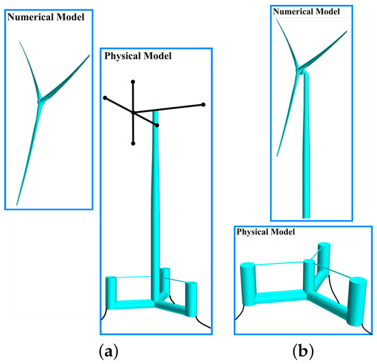
Figure 23.
Numerically modeled aerodynamics hybrid tests. (a) Aero-rotor coupling; (b) Tower-base coupling.
In the tower-base coupling scheme, the physical and numerical models are separated from each other by a clear boundary, and the rotor elasticity can be represented more realistically for the scaled model through the numerical model [391,392]. However, the coupling strategy must respond with a relatively high frequency to properly mimic the dynamic behavior at the tower–platform connection. Consequently, it is relatively sensitive to the bandwidth and time delay of the platform motion measurements and actuators [391]. The actuation mechanism requirements necessary to guarantee the hybrid model testing accuracy using the tower-base coupling method are presented in [393]. Additionally, the effects of ignoring some aerodynamic load components on the same testing method are evaluated in [394].
In the aero-rotor coupling, the blades are modeled physically as non-rotating mass and inertia. The numerical model computes the aerodynamic loads acting on rotor blades, which are assumed to be rigid and massless, neglecting the tower loads [15,391].
In [15], the authors focus on hybrid testing based on aero-rotor coupling to assess the behavior of a 1:30 scaled of a 5 MW braceless semi-submersible FWTS in a wave basin. The hybrid testing procedure is verified in [395], where it is shown that the test results are highly repeatable, allowing the assessment of the responses of the FWTS. The hybrid testing model presented in [15,395] is used also in [396] to calibrate the viscous drag coefficients of the ME of a coupled PF-ME-BEM numerical model developed for the braceless FWTS.
The aerodynamic loads can be applied to the physical model within a wave basin, using a duct fan, which replaces the rotor, as shown in [397,398]. By controlling the fan’s rpm based on simulation results, it can generate a thrust force equivalent to that of the full-scale prototype.
A 1:80 scaled model of a 5 MW FWTS is physically tested in [399] in a wave basin, where the thrust force is accounted for by a fan installed on top of the tower. Ref. [400] tests a 1:36 Froude-scaled FWTS with two rotors, where the steady wind loads are simulated by two ducted fans and gyroscopic loads by weighted rotating beams. It is shown that the uncertainty is highly affected by the simulated thrust loads, while the gyroscopic loads have negligible effects.
The single-fan method, which can only generate the thrust force, is later extended in [401,402,403], where a multi-fan system is used to consider the effects from other aerodynamic loads besides the thrust force. Refs. [390,404] develop a new hybrid testing approach, where a cable-based actuator prescribes the correct thrust force value to an FWTS model in a wave basin. Refs. [15,395,396] also use a similar approach to test the 1:30 scale braceless FWTS mentioned earlier, where the nacelle is substituted with a square frame connected to several pulleys through thin cables, which are used as actuators.
- Numerically modeled hydrodynamics
In the numerically modeled hydrodynamic hybrid tests, also referred to as hydrodynamics in the virtual subsystem, hydrodynamics is treated within a numerical model, while aerodynamics is represented physically through a model test within a wind tunnel, as shown schematically in Figure 24. This type of test gains importance, especially in the case of the wake evaluation of FWTS. The main focus of this type of testing is the development of a reliable actuation system to prescribe the motions of the platform to the wind turbine.
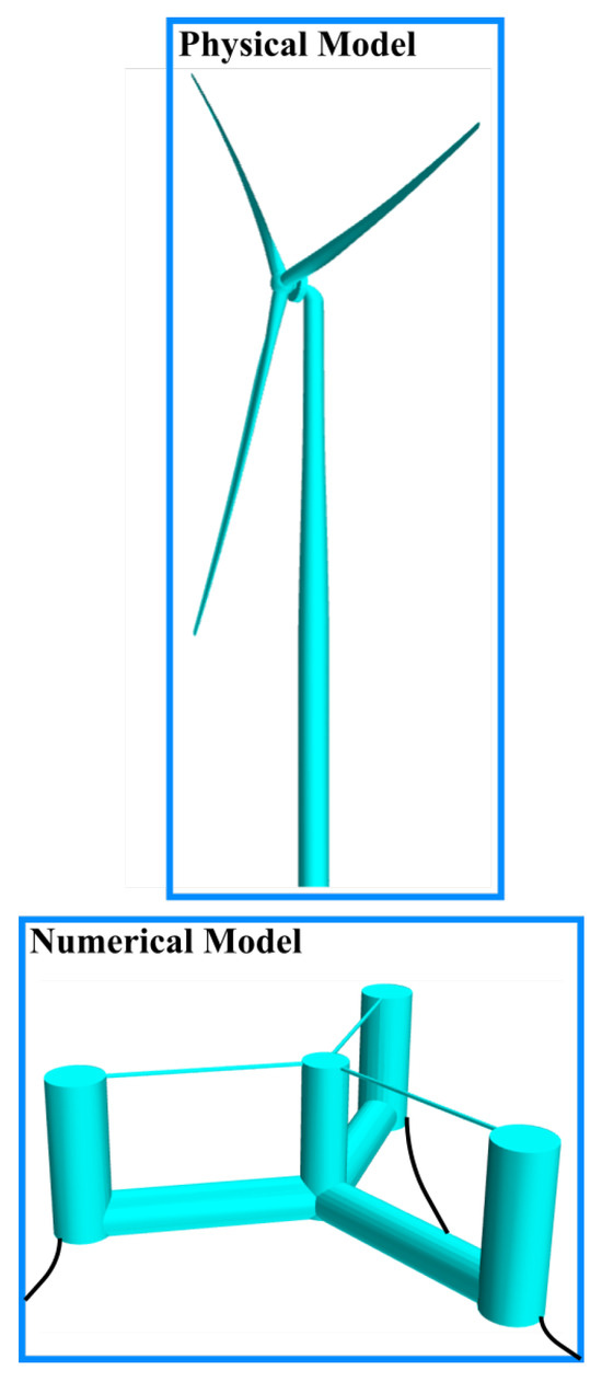
Figure 24.
Numerically modeled hydrodynamics hybrid tests.
In the simplest case of this kind of test, the scaled wind turbine model undergoes a forced harmonic motion due to the platform motions in a certain degree of freedom [405,406,407,408,409,410,411].
The complexity increases when the platform motions are estimated from a numerical model and then prescribed to the wind turbine through an actuation mechanism.
In this regard, a two-degree-of-freedom mechanism that can reproduce the pitch/roll rotations and the surge/sway movements for an FWTS is developed in [412]. The movements are calculated using the results from a real-time simulation of a hydrodynamic numerical model based on the ME implemented in MATLAB/Simulink. The arrangement is later used in [405] to evaluate the OC5 FWTS motions by accounting for the first-order and second-order low-frequency hydrodynamic loads, employing WAMIT software. Additionally, the same system is tested in [413] to assess the FWTS behavior under the actions of the active blade and pitch control, as proposed in [414]. The system is later extended in [415] into a six-degree-of-freedom mechanism called HexaFloat, which can simulate the FWTS dynamics subject to normal operational conditions. Refs. [416,417,418] use the HexaFloat to evaluate the dynamic responses of an FWTS under unsteady aerodynamics and turbine controller action.
6.2. Field Testing
Despite the existence of several real-scale FWTS, such as Hywind in Norway and WindFloat in Portugal [419,420], there is a shortage of full-scale field measurements of the responses of these structures in the public domain, which leads to a limited number of validation studies of simulation tools against field data. This is crucial for better understanding the coupled dynamic behavior of these machines and gaining confidence in the predictions provided by simulation tools. In recent years, a few works have reported data from field measurements and used these data to validate numerical simulation tools for a range of FWTS concepts [22,421,422,423,424,425].
In this regard, the field measurements from a 2 MW hybrid concrete-steel Haenkaze FWTS commissioned in 2013 in Japan are used in [423,424] to validate a coupled hydro-aero-elastic simulation tool for FWTS. It is argued that the spatial coherence of the wind field plays a significant role in the accurate prediction of the responses.
The measured and calculated data for a 7 MW V-shaped semi-submersible FWTS in Japan are reported in [426], where the calculations are performed using the commercial code Bladed.
The measurement data during a six-month operation for a concrete barge-type FWTS installed in 2018 in France are presented in [427]. Ref. [428] calculates the motion RAOs and turbine loads using OpenFAST-OrcaFlex code.
The validation of the OpenFAST code, based on measurements from the Statoil Hywind Demo, is reported in [421,422]. Except for the roll and yaw responses at low frequencies, the OpenFAST reasonably reproduces the measured platform motions.
A 20 kW VolturnUS, a 1:8 Froude-scaled model of the concrete 6 MW VolturnUS semi-submersible floating wind turbine, was tested in the US for 18 months [22]. The test site’s environmental conditions are chosen so that the turbine model produces a thrust force equivalent to the prototype.
The influence of wave-/wind-induced oscillations on the energy production of the WindFloat is assessed in [429]. The nacelle movements are recorded using accelerometer sensors. The wind data are measured using a nacelle-mounted LiDAR system, and the wave data are recorded using a buoy equipped with a LiDAR system.
7. Summary and Conclusions
Various methods with fidelity levels are available to analyze the FWTS-coupled hydro–aero–structural dynamics at each design stage.
The linear models in the frequency domain with the lowest level of fidelity are suitable in the early conceptual design phases for dimensioning and optimizing the FWTS.
At the preliminary design stages, mid-fidelity fully coupled nonlinear time-domain models are used to analyze the dynamic responses of FWTS under various conditions to assess the operating, fatigue, and extreme loads correctly. These models are also excellent for the control design of FWTS to reduce the structural loads and platform motions. The complex aerodynamic behavior of the FWTS is better captured by the FVW method than by the BEM method. This is because the FVW method can characterize the wake evolution of a wind turbine over time, which may give more reliable predictions in the case of the FWTS due to the possibility of rotor movement in its own wake. Additionally, the accuracy of hydrodynamic modeling is increased by accounting for second-order wave loads using full sum- and difference-frequency QTFs. The QTFs can be calibrated using data from physical tests or high-fidelity CFD simulations to enhance the low-frequency predictions further. For the dynamic structural assessment of FWTS, using nonlinear beam theories is preferred over the modal analysis in the case of large blade deformations.
The high-fidelity coupled CFD-FEA methods are used in the last design phases, where more in-depth investigations are required for extreme conditions and intricate flow conditions. These methods are suitable for fine-tuning the design, as well as the calibration of the low- and mid-fidelity models. However, due to the high computational demand of a coupled CFD-FEA method, the high-fidelity analyses of FWTS are mainly restricted to aeroelastic and hydro-aerodynamic studies. In this regard, little attention has been given to the impact of the near-wall grid resolution on CFD simulations of FWTS. It is common to couple high-fidelity CFD and FEA methods with low- and medium-fidelity models, such as PF, MBD, or BEM, to reduce the computational demand.
Modeling the mooring system is also part of all numerical modeling of FWTS. In this regard, during a coupled analysis, the dynamic effects of mooring cables for floating wind turbine systems must be accounted for through the use of dynamic models such as lumped mass, FEA, and FD methods for a more reliable estimation of the ultimate and fatigue loads in a mooring line and the correct modeling of the peak tension in extreme events.
Finally, the physical tests are used to validate the numerical models to gain more confidence in these numerical tools. However, the shortage of full-scale field measurements for FWTS leads to a partial validation study of simulation tools. The physical tests also enhance our understanding of the physical aspect of the problem by revealing complex phenomena that may only be recognized using physical modeling techniques. This enhanced understanding eventually leads to an improvement in the low- and mid-fidelity numerical models. In the full physical testing—to solve the issue of the Reynolds number dissimilarity between the model and prototype—several solutions are outlined. Hybrid testing is an intriguing option to solve this issue, which can be categorized into numerically modeled aerodynamics and hydrodynamics.
Finally, based on the review carried out in this article, the following possible future research is identified to address challenges in modeling FWTS dynamics that persist to date:
- The accuracy of the mid-fidelity tools can be improved by incorporating the effect of vortex-induced motion (VIM). This effect originates from currents or low-frequency waves and results in time-varying loading emanating from pressure fluctuations, owing to vortex shedding from the platform components or mooring lines. The problem arises once the vortex shedding occurs at a frequency close to the structure’s natural frequency, which leads to the resonation of the two frequencies and large oscillation amplitudes.
- The computational cost of CFD simulations of FWTS in waves can be reduced by coupling a fully nonlinear potential solver capable of describing the nonlinear, three-dimensional wave field with CFD solvers governing the flow field in the FWTS vicinity. Using this strategy, it is possible to account for inherently nonlinear second-order effects.
- A more systematic study is required to assess the impact of different materials for mooring lines on the platform’s motions and the overall power production.
- Due to the wave’s second-order effects, more research is required to evaluate the structural fatigue damage for ultra-large FWTS.
- Modeling slender offshore structures in waves as rigid might lead to overestimating fluid forces. For example, modeling an offshore wind turbine foundation as completely rigid, commonly adopted in numerical and experimental analyses, may give very conservative wave forces. The size of offshore wind turbines has grown in the last few years, but the size of the platforms used to support these huge machines is also increasing. It may be crucial to consider the structural dynamics (hydro-elasticity) of these platforms in numerical and experimental studies, which are generally not considered.
- During numerically modeled aerodynamic hybrid tests, the aerodynamic loads are typically calculated using a BEM method, which cannot accurately capture the effects of unsteady loading, dynamic inflow, and turbine–wake interactions. However, this issue can be avoided by using an FVW method.
- One source of error in hybrid testing comes from the numerical models used. One solution to this problem is to avoid using these numerical models by coupling the two types of hybrid tests for an FWTS model via an internet connection.
- To gain confidence in the numerical and experimental results, detailed verifications and validation studies are essential for quantifying errors and uncertainties. It is also crucial to identify the limitations of the hybrid testing by using the same FWTS model in both methods, i.e., numerically modeled aerodynamics and hydrodynamics. Further, in the case of CFD and FEA, sensitivity studies are required to test different element sizes, spatial and temporal discretization schemes, turbulence models, mooring line models, etc.
- Artificial intelligence can be used to substitute the numerical subsystem in hybrid testing, thus increasing the efficiency of this type of test.
- Field measurements detailing the impact of FWTS motions on their aerodynamic performance and power generation are crucial, especially for validating the numerical models and understanding where improvements are essential for these models.
Author Contributions
M.M.A.: conceptualization, methodology, formal analysis, investigation, data curation, writing—original draft preparation, writing—review and editing, and visualization; M.S.: conceptualization, writing—review and editing; S.F.E.: Conceptualization, writing—review and editing, supervision, project administration, and funding acquisition. All authors have read and agreed to the published version of the manuscript.
Funding
This research was funded by: 1. Human Resources Program PRH-18 from the Agência Nacional do Petróleo, Gás Natural e Biocombustíveis (ANP) and Financiadora de Estudos e Projetos (FINEP). 2. Carlos Chagas Filho Foundation–FAPERJ (Grant # E-26/210.796/2021 (262842)). 3. Brazilian Research Council–CNPq (Grant # 303182/2022-9) 4. Center of Excellence in Digital Transformation and Artificial Intelligence of the Rio de Janeiro State-Network in Renewable Energy and Climate Change, Carlos Chagas Filho Foundation–FAPERJ (Grant # E-26/290.023/2021). 5. CNOOC Petroleum Brasil Ltda (2022-PR-RDI-002).
Conflicts of Interest
The authors declare no conflicts of interest.
References
- Musial, W.; Spitsen, P.; Duffy, P.; Beiter, P.; Marquis, M.; Hammond, R.; Shields, M. Offshore Wind Market Report: 2022 Edition; Technical Report; National Renewable Energy Lab. (NREL): Golden, CO, USA, 2022. [Google Scholar]
- Wind Europe. Floating Offshore Wind Vision Statement; Wind Europe: Brussels, Belgium, 2017. [Google Scholar]
- Shadman, M.; Amiri, M.M.; Silva, C.; Estefen, S.F.; La Rovere, E. Environmental impacts of offshore wind installation, operation and maintenance, and decommissioning activities: A case study of Brazil. Renew. Sustain. Energy Rev. 2021, 144, 110994. [Google Scholar] [CrossRef]
- Sánchez, S.; López-Gutiérrez, J.S.; Negro, V.; Esteban, M.D. Foundations in offshore wind farms: Evolution, characteristics and range of use. Analysis of main dimensional parameters in monopile foundations. J. Mar. Sci. Eng. 2019, 7, 441. [Google Scholar] [CrossRef]
- Faraggiana, E.; Giorgi, G.; Sirigu, M.; Ghigo, A.; Bracco, G.; Mattiazzo, G. A review of numerical modelling and optimisation of the floating support structure for offshore wind turbines. J. Ocean Eng. Mar. Energy 2022, 8, 433–456. [Google Scholar] [CrossRef]
- Liu, Y.; Li, S.; Yi, Q.; Chen, D. Developments in semi-submersible floating foundations supporting wind turbines: A comprehensive review. Renew. Sustain. Energy Rev. 2016, 60, 433–449. [Google Scholar] [CrossRef]
- Roddier, D.; Cermelli, C.; Weinstein, A. WindFloat: A floating foundation for offshore wind turbines—Part I: Design basis and qualification process. In Proceedings of the International Conference on Offshore Mechanics and Arctic Engineering, Honolulu, HI, USA, 31 May– 5 June 2009; Volume 43444, pp. 845–853. [Google Scholar]
- Subbulakshmi, A.; Verma, M.; Keerthana, M.; Sasmal, S.; Harikrishna, P.; Kapuria, S. Recent advances in experimental and numerical methods for dynamic analysis of floating offshore wind turbines—An integrated review. Renew. Sustain. Energy Rev. 2022, 164, 112525. [Google Scholar] [CrossRef]
- Yagihashi, K.; Tateno, Y.; Sakakibara, H.; Manabe, H. Dynamic cable installation for Fukushima floating offshore wind farm demonstration project. In Proceedings of the Proceeding Jicable, Versailles, France, 21–25 June 2015. [Google Scholar]
- Umoh, K.; Lemon, M. Drivers for and barriers to the take up of floating offshore wind technology: A comparison of Scotland and South Africa. Energies 2020, 13, 5618. [Google Scholar] [CrossRef]
- Robertson, A.; Jonkman, J.; Vorpahl, F.; Popko, W.; Qvist, J.; Frøyd, L.; Chen, X.; Azcona, J.; Uzunoglu, E.; Guedes Soares, C.; et al. Offshore code comparison collaboration continuation within IEA wind task 30: Phase II results regarding a floating semisubmersible wind system. In Proceedings of the International Conference on Offshore Mechanics and Arctic Engineering. American Society of Mechanical Engineers, San Francisco, CA, USA, 8–13 June 2014; Volume 45547, p. V09BT09A012. [Google Scholar]
- Mahfouz, M.Y.; Molins, C.; Trubat, P.; Hernández, S.; Vigara, F.; Pegalajar-Jurado, A.; Bredmose, H.; Salari, M. Response of the International Energy Agency (IEA) Wind 15 MW WindCrete and Activefloat floating wind turbines to wind and second-order waves. Wind Energy Sci. 2021, 6, 867–883. [Google Scholar] [CrossRef]
- Allen, C.; Viscelli, A.; Dagher, H.; Goupee, A.; Gaertner, E.; Abbas, N.; Hall, M.; Barter, G. Definition of the UMaine VolturnUS-S Reference Platform Developed for the IEA Wind 15-Megawatt Offshore Reference Wind Turbine; Technical Report; National Renewable Energy Lab. (NREL): Golden, CO, USA, 2020. [Google Scholar]
- Roddier, D.; Cermelli, C.; Aubault, A.; Weinstein, A. WindFloat: A floating foundation for offshore wind turbines. J. Renew. Sustain. Energy 2010, 2, 033104. [Google Scholar] [CrossRef]
- Sauder, T.; Chabaud, V.; Thys, M.; Bachynski, E.E.; Sæther, L.O. Real-time hybrid model testing of a braceless semi-submersible wind turbine: Part I—The hybrid approach. In Proceedings of the International Conference on Offshore Mechanics and Arctic Engineering. American Society of Mechanical Engineers, Busan, Republic of Korea, 19–24 June 2016; Volume 49972, p. V006T09A039. [Google Scholar]
- Cermelli, C.; Roddier, D.; Aubault, A. WindFloat: A floating foundation for offshore wind turbines—part II: Hydrodynamics analysis. In Proceedings of the International Conference on Offshore Mechanics and Arctic Engineering, Honolulu, HI, USA, 31 May–5 June 2009; Volume 43444, pp. 135–143. [Google Scholar]
- Luan, C. Design and Analysis for a Steel Braceless Semi-Submersible Hull for Supporting a 5-MW Horizontal Axis Wind Turbine. 2018. Available online: https://ntnuopen.ntnu.no/ntnu-xmlui/handle/11250/2563372 (accessed on 20 February 2024).
- Robertson, A.; Jonkman, J.; Masciola, M.; Song, H.; Goupee, A.; Coulling, A.; Luan, C. Definition of the Semisubmersible Floating System for Phase II of OC4; Technical Report; National Renewable Energy Lab. (NREL): Golden, CO, USA, 2014. [Google Scholar]
- Jonkman, J.; Butterfield, S.; Musial, W.; Scott, G. Definition of a 5-MW Reference Wind Turbine for Offshore System Development; Technical Report; National Renewable Energy Lab. (NREL): Golden, CO, USA, 2009. [Google Scholar]
- Liu, Z.; Fan, Y.; Wang, W.; Qian, G. Numerical study of a proposed semi-submersible floating platform with different numbers of offset columns based on the DeepCwind prototype for improving the wave-resistance ability. Appl. Sci. 2019, 9, 1255. [Google Scholar] [CrossRef]
- James, R.; Ros, M.C. Floating offshore wind: Market and technology review. Carbon Trust 2015, 439. [Google Scholar]
- Viselli, A.M.; Goupee, A.J.; Dagher, H.J. Model test of a 1: 8-scale floating wind turbine offshore in the gulf of maine. J. Offshore Mech. Arct. Eng. 2015, 137, 041901. [Google Scholar] [CrossRef]
- Mathern, A.; von der Haar, C.; Marx, S. Concrete support structures for offshore wind turbines: Current status, challenges, and future trends. Energies 2021, 14, 1995. [Google Scholar] [CrossRef]
- Johansen, T.; Nissen-Lie, T.; Aaberg Midtsund, M.; Wiley, T.; Bayat, A.; Fulger, S.; O’Malley, J.; Færøy Sæbo, E. Comparative Study of Concrete and Steel Substructures for FOWT; Technical Report; Det Norske Veritas (DNV): Bærum, Norway, 2022. [Google Scholar]
- Lamei, A.; Hayatdavoodi, M. On motion analysis and elastic response of floating offshore wind turbines. J. Ocean Eng. Mar. Energy 2020, 6, 71–90. [Google Scholar] [CrossRef]
- Shi, W.; Liu, Y.; Wang, W.; Cui, L.; Li, X. Numerical study of an ice-offshore wind turbine structure interaction with the pile-soil interaction under stochastic wind loads. Ocean Eng. 2023, 273, 113984. [Google Scholar] [CrossRef]
- Musial, W.; Butterfield, S.; Boone, A. Feasibility of floating platform systems for wind turbines. In Proceedings of the 42nd AIAA Aerospace Sciences Meeting and Exhibit, Reno, Nevada, 5–8 January 2004; p. 1007. [Google Scholar]
- Veers, P.; Bottasso, C.; Manuel, L.; Naughton, J.; Pao, L.; Paquette, J.; Robertson, A.; Robinson, M.; Ananthan, S.; Barlas, A.; et al. Grand Challenges in the Design, Manufacture, and Operation of Future Wind Turbine Systems. Wind. Energy Sci. Discuss. 2023, 8, 1071–1131. [Google Scholar] [CrossRef]
- Sebastian, T. The Aerodynamics and Near Wake of an Offshore Floating Horizontal Axis Wind Turbine. Ph.D. Thesis, University of Massachusetts Amherst, Amherst, MA, USA, 2012. [Google Scholar]
- Matha, D.; Cruz, J.; Masciola, M.; Bachynski, E.E.; Atcheson, M.; Goupee, A.J.; Gueydon, S.M.; Robertson, A.N. Modelling of Floating Offshore Wind Technologies. In Floating Offshore Wind Energy: The Next Generation of Wind Energy; Springer: Cham, Switzerland, 2016; pp. 133–240. [Google Scholar]
- Henderson, A.; Collu, M.; Masciola, M. Floating offshore wind energy: The next generation of wind energy, chapter Overview of floating offshore wind technologies. Springer 2016, 15, 124. [Google Scholar]
- Jin, X.; Xie, S.; He, J.; Lin, Y.; Wang, Y.; Wang, N. Optimization of tuned mass damper parameters for floating wind turbines by using the artificial fish swarm algorithm. Ocean Eng. 2018, 167, 130–141. [Google Scholar] [CrossRef]
- Coudurier, C.; Lepreux, O.; Petit, N. Modelling of a tuned liquid multi-column damper. Application to floating wind turbine for improved robustness against wave incidence. Ocean Eng. 2018, 165, 277–292. [Google Scholar] [CrossRef]
- Alotta, G.; Laface, V.; Failla, G.; Ruzzo, C.; Arena, F. A novel concept of floating absorber for motion mitigation in floating offshore wind turbines. Eng. Struct. 2023, 294, 116554. [Google Scholar] [CrossRef]
- Jahangiri, V.; Sun, C. A novel three dimensional nonlinear tuned mass damper and its application in floating offshore wind turbines. Ocean Eng. 2022, 250, 110703. [Google Scholar] [CrossRef]
- He, J.; Jin, X.; Xie, S.; Cao, L.; Lin, Y.; Wang, N. Multi-body dynamics modeling and TMD optimization based on the improved AFSA for floating wind turbines. Renew. Energy 2019, 141, 305–321. [Google Scholar] [CrossRef]
- Zhang, Z.; Høeg, C. Inerter-enhanced tuned mass damper for vibration damping of floating offshore wind turbines. Ocean Eng. 2021, 223, 108663. [Google Scholar] [CrossRef]
- Catapult, O. Floating Offshore Wind: Cost Reduction Pathways to Subsidy Free; ORE CATAPULT Report; ORE CATAPULT: Blyth, UK, 2022. [Google Scholar]
- Sykes, V.; Collu, M.; Coraddu, A. A review and analysis of optimisation techniques applied to floating offshore wind platforms. Ocean Eng. 2023, 285, 115247. [Google Scholar] [CrossRef]
- Viré, A.; Xiang, J.; Piggott, M.; Cotter, C.; Pain, C. Towards the fully-coupled numerical modelling of floating wind turbines. Energy Procedia 2013, 35, 43–51. [Google Scholar] [CrossRef]
- Li, Y.; Castro, A.; Sinokrot, T.; Prescott, W.; Carrica, P. Coupled multi-body dynamics and CFD for wind turbine simulation including explicit wind turbulence. Renew. Energy 2015, 76, 338–361. [Google Scholar] [CrossRef]
- Campanile, A.; Piscopo, V.; Scamardella, A. Mooring design and selection for floating offshore wind turbines on intermediate and deep water depths. Ocean Eng. 2018, 148, 349–360. [Google Scholar] [CrossRef]
- Collu, M.; Brennan, F.; Patel, M. Conceptual design of a floating support structure for an offshore vertical axis wind turbine: The lessons learnt. Ships Offshore Struct. 2014, 9, 3–21. [Google Scholar] [CrossRef]
- Dou, S.; Pegalajar-Jurado, A.; Wang, S.; Bredmose, H.; Stolpe, M. Optimization of floating wind turbine support structures using frequency-domain analysis and analytical gradients. J. Phys. Conf. Ser. 2020, 1618, 042028. [Google Scholar] [CrossRef]
- Lemmer, F.; Yu, W.; Luhmann, B.; Schlipf, D.; Cheng, P.W. Multibody modeling for concept-level floating offshore wind turbine design. Multibody Syst. Dyn. 2020, 49, 203–236. [Google Scholar] [CrossRef]
- Tran, T.T.; Kim, D.H. The aerodynamic interference effects of a floating offshore wind turbine experiencing platform pitching and yawing motions. J. Mech. Sci. Technol. 2015, 29, 549–561. [Google Scholar] [CrossRef]
- Bauchau, O.A. Computational schemes for flexible, nonlinear multi-body systems. Multibody Syst. Dyn. 1998, 2, 169–225. [Google Scholar] [CrossRef]
- Otter, A.; Murphy, J.; Pakrashi, V.; Robertson, A.; Desmond, C. A review of modelling techniques for floating offshore wind turbines. Wind Energy 2022, 25, 831–857. [Google Scholar] [CrossRef]
- Jonkman, J.; Wright, A.; Barter, G.; Hall, M.; Allison, J.; Herber, D.R. Functional requirements for the WEIS toolset to enable controls co-design of floating offshore wind turbines. In Proceedings of the International Conference on Offshore Mechanics and Arctic Engineering. American Society of Mechanical Engineers, Virtual, 16–17 February 2021; Volume 84768, p. V001T01A007. [Google Scholar]
- Rathod, U.H.; Kulkarni, V.; Saha, U.K. On the application of machine learning in savonius wind turbine technology: An estimation of turbine performance using artificial neural network and genetic expression programming. J. Energy Resour. Technol. 2022, 144, 061301. [Google Scholar] [CrossRef]
- Jiang, X.; Day, S.; Clelland, D.; Liang, X. Analysis and real-time prediction of the full-scale thrust for floating wind turbine based on artificial intelligence. Ocean Eng. 2019, 175, 207–216. [Google Scholar] [CrossRef]
- Lemmer, F.; Yu, W.; Steinacker, H.; Skandali, D.; Raach, S. Advances on reduced-order modeling of floating offshore wind turbines. In Proceedings of the International Conference on Offshore Mechanics and Arctic Engineering. American Society of Mechanical Engineers, Virtual, 21–30 June 2021; Volume 85192, p. V009T09A034. [Google Scholar]
- O’Donnell, D.; Murphy, J.; Desmond, C.; Jaksic, V.; Pakrashi, V. Tuned liquid column damper based reduction of dynamic responses of scaled offshore platforms in different ocean wave basins. J. Phys. Conf. Ser. 2017, 842, 012043. [Google Scholar] [CrossRef]
- Lackner, M.A. An investigation of variable power collective pitch control for load mitigation of floating offshore wind turbines. Wind Energy 2013, 16, 435–444. [Google Scholar] [CrossRef]
- Savenije, F.; Peeringa, J. Control development for floating wind. J. Phys. Conf. Ser. 2014, 524, 012090. [Google Scholar] [CrossRef]
- Han, D.; Li, X.; Wang, W.; Su, X. Dynamic modeling and vibration control of barge offshore wind turbine using tuned liquid column damper in floating platform. Ocean Eng. 2023, 276, 114299. [Google Scholar] [CrossRef]
- Salic, T.; Charpentier, J.F.; Benbouzid, M.; Le Boulluec, M. Control strategies for floating offshore wind turbine: Challenges and trends. Electronics 2019, 8, 1185. [Google Scholar] [CrossRef]
- Jonkman, J.M.; Buhl, M. FAST User’s Guide; Report NREL/EL-500-38230 (previously NREL/EL-500-29798); National Renewable Energy Laboratory (NREL): Golden, CO, USA, 2005. [Google Scholar]
- Jonkman, J.M.; Wright, A.D.; Hayman, G.J.; Robertson, A.N. Full-system linearization for floating offshore wind turbines in OpenFAST. In Proceedings of the International Conference on Offshore Mechanics and Arctic Engineering. American Society of Mechanical Engineers, San Francisco, CA, USA, 4–7 November 2018; Volume 51975, p. V001T01A028. [Google Scholar]
- Liu, Y.; Ge, D.; Bai, X.; Li, L. A CFD Study of Vortex-Induced Motions of a Semi-Submersible Floating Offshore Wind Turbine. Energies 2023, 16, 698. [Google Scholar] [CrossRef]
- Li, H.; Bachynski-Polić, E.E. Experimental and numerically obtained low-frequency radiation characteristics of the OC5-DeepCwind semisubmersible. Ocean Eng. 2021, 232, 109130. [Google Scholar] [CrossRef]
- Li, H.; Bachynski-Polić, E.E. Validation and application of nonlinear hydrodynamics from CFD in an engineering model of a semi-submersible floating wind turbine. Mar. Struct. 2021, 79, 103054. [Google Scholar] [CrossRef]
- Li, H.; Bachynski-Polić, E.E. Analysis of difference-frequency wave loads and quadratic transfer functions on a restrained semi-submersible floating wind turbine. Ocean Eng. 2021, 232, 109165. [Google Scholar] [CrossRef]
- Zhang, D.; Paterson, E. A study of wave forces on an offshore platform by direct CFD and Morison equation. E3S Web Conf. 2015, 5, 04002. [Google Scholar] [CrossRef]
- Chen, P.; Chen, J.; Hu, Z. Review of experimental-numerical methodologies and challenges for floating offshore wind turbines. J. Mar. Sci. Appl. 2020, 19, 339–361. [Google Scholar] [CrossRef]
- Hmedi, M.; Uzunoglu, E.; Soares, C.G. Review of hybrid model testing approaches for floating wind turbines. Trends Marit. Technol. Eng. 2022, 2, 421–428. [Google Scholar]
- Chen, C.; Ma, Y.; Fan, T. Review of model experimental methods focusing on aerodynamic simulation of floating offshore wind turbines. Renew. Sustain. Energy Rev. 2022, 157, 112036. [Google Scholar] [CrossRef]
- Gueydon, S.; Bayati, I.; de Ridder, E. Discussion of solutions for basin model tests of FOWTs in combined waves and wind. Ocean Eng. 2020, 209, 107288. [Google Scholar] [CrossRef]
- Hall, M.; Housner, S.; Zalkind, D.; Bortolotti, P.; Ogden, D.; Barter, G. An open-source frequency-domain model for floating wind turbine design optimization. J. Phys. Conf. Ser. 2022, 2265, 042020. [Google Scholar] [CrossRef]
- Pollini, N.; Pegalajar-Jurado, A.; Bredmose, H. Design optimization of a TetraSpar-type floater and tower for the IEA Wind 15 MW reference wind turbine. Mar. Struct. 2023, 90, 103437. [Google Scholar] [CrossRef]
- Pegalajar-Jurado, A.; Borg, M.; Bredmose, H. An efficient frequency-domain model for quick load analysis of floating offshore wind turbines. Wind Energy Sci. 2018, 3, 693–712. [Google Scholar] [CrossRef]
- Al-Solihat, M.K.; Nahon, M. Stiffness of slack and taut moorings. Ships Offshore Struct. 2016, 11, 890–904. [Google Scholar] [CrossRef]
- Hegseth, J.M.; Bachynski, E.E. A semi-analytical frequency domain model for efficient design evaluation of spar floating wind turbines. Mar. Struct. 2019, 64, 186–210. [Google Scholar] [CrossRef]
- Ferri, G.; Marino, E.; Bruschi, N.; Borri, C. Platform and mooring system optimization of a 10 MW semisubmersible offshore wind turbine. Renew. Energy 2022, 182, 1152–1170. [Google Scholar] [CrossRef]
- Tran, T.T.; Kim, D.H. The platform pitching motion of floating offshore wind turbine: A preliminary unsteady aerodynamic analysis. J. Wind Eng. Ind. Aerodyn. 2015, 142, 65–81. [Google Scholar] [CrossRef]
- Karimi, M.; Hall, M.; Buckham, B.; Crawford, C. A multi-objective design optimization approach for floating offshore wind turbine support structures. J. Ocean Eng. Mar. Energy 2017, 3, 69–87. [Google Scholar] [CrossRef]
- Chakrabarti, S.K. Hydrodynamics of Offshore Structures; WIT Press: Southampton, UK, 1987. [Google Scholar]
- Xu, K.; Shao, Y.; Gao, Z.; Moan, T. A study on fully nonlinear wave load effects on floating wind turbine. J. Fluids Struct. 2019, 88, 216–240. [Google Scholar] [CrossRef]
- Tran, T.T.; Kim, D.H. The coupled dynamic response computation for a semi-submersible platform of floating offshore wind turbine. J. Wind Eng. Ind. Aerodyn. 2015, 147, 104–119. [Google Scholar] [CrossRef]
- Veritas, N. Environmental Conditions and Environmental Loads; Det Norske Veritas: Oslo, Norway, 2000. [Google Scholar]
- Faltinsen, O. Sea Loads on Ships and Offshore Structures; Cambridge University Press: Southampton, UK, 1993; Volume 1. [Google Scholar]
- Newman, J.N. Marine Hydrodynamics; The MIT Press: Southampton, UK, 2018. [Google Scholar]
- Robertson, A.N.; Wendt, F.; Jonkman, J.M.; Popko, W.; Dagher, H.; Gueydon, S.; Qvist, J.; Vittori, F.; Azcona, J.; Uzunoglu, E.; et al. OC5 project phase II: Validation of global loads of the DeepCwind floating semisubmersible wind turbine. Energy Procedia 2017, 137, 38–57. [Google Scholar] [CrossRef]
- Hu, C.; Sueyoshi, M.; Liu, C.; Liu, Y. Hydrodynamic analysis of a semi-submersible type floating wind turbine. In Proceedings of the Eleventh ISOPE Pacific/Asia Offshore Mechanics Symposium, Shanghai, China, 12–14 October 2014. [Google Scholar]
- Lee, C.H.; Newman, J. Computation of wave effects using the panel method. WIT Trans. State-Sci. Eng. 2005, 18, 211–251. [Google Scholar]
- Uçar, M.; Uzunoğlu, E.; Oğuz, E. Comparison and Evaluation of Open-Source Panel Method Codes against Commercial Codes. Gemi ve Deniz Teknolojisi 2021, 221, 86–108. [Google Scholar] [CrossRef]
- Shokouhian, M.; Head, M.; Seo, J.; Schaffer, W.; Adams, G. Hydrodynamic response of a semi-submersible platform to support a wind turbine. J. Mar. Eng. Technol. 2021, 20, 170–185. [Google Scholar] [CrossRef]
- Benitz, M.A.; Schmidt, D.P.; Lackner, M.A.; Stewart, G.M.; Jonkman, J.; Robertson, A. Validation of hydrodynamic load models using CFD for the OC4-DeepCwind semisubmersible. In Proceedings of the International Conference on Offshore Mechanics and Arctic Engineering, St. John’s, Canada, 31 May–5 June 2015; Volume 56574, p. V009T09A037. [Google Scholar]
- Bussemakers, P.J.M. Validation of Aero-Hydro-Servo-Elastic Load and Motion Simulations in BHawC/OrcaFlex for the Hywind Scotland Floating Offshore Wind Farm. Master’s Thesis, NTNU, Trondheim, Norway, 2020. [Google Scholar]
- Clément, C.; Bozonnet, P.; Vinay, G.; Pagnier, P.; Nadal, A.B.; Réveillon, J. Evaluation of Morison approach with CFD modelling on a surface-piercing cylinder towards the investigation of FOWT Hydrodynamics. Ocean Eng. 2022, 251, 111042. [Google Scholar] [CrossRef]
- Jonkman, J.M.; Robertson, A.; Hayman, G.J. HydroDyn User’s Guide and Theory Manual; National Renewable Energy Laboratory: Golden, CO, USA, 2014. [Google Scholar]
- Matha, D.; Schlipf, M.; Pereira, R.; Jonkman, J. Challenges in simulation of aerodynamics, hydrodynamics, and mooring-line dynamics of floating offshore wind turbines. In Proceedings of the ISOPE International Ocean and Polar Engineering Conference, Maui, HI, USA, 19–24 June 2011; p. ISOPE-I. [Google Scholar]
- Duarte, T.M.; Sarmento, A.J.; Jonkman, J.M. Effects of second-order hydrodynamic forces on floating offshore wind turbines. In Proceedings of the 32nd ASME Wind Energy Symposium, National Harbor, MD, USA, 13–17 January 2014; p. 0361. [Google Scholar]
- Servan-Camas, B.; Gutierrez-Romero, J.E.; Garcia-Espinosa, J. A time-domain second-order FEM model for the wave diffraction-radiation problem. Validation with a semisubmersible platform. Mar. Struct. 2018, 58, 278–300. [Google Scholar] [CrossRef]
- Gutiérrez-Romero, J.E.; García-Espinosa, J.; Serván-Camas, B.; Zamora-Parra, B. Non-linear dynamic analysis of the response of moored floating structures. Mar. Struct. 2016, 49, 116–137. [Google Scholar] [CrossRef]
- Lucas, J. Comparison of First and Second-Order Hydrodynamic Results for Floating Offshore Wind Structures; Report Ref: 11594br02a; DNV GL Garrad Hassan: Bærum, Norway, 2011. [Google Scholar]
- Bayati, I.; Gueydon, S.; Belloli, M. Study of the effect of water depth on potential flow solution of the OC4 semisubmersible floating offshore wind turbine. Energy Procedia 2015, 80, 168–176. [Google Scholar] [CrossRef]
- Zhang, L.; Shi, W.; Karimirad, M.; Michailides, C.; Jiang, Z. Second-order hydrodynamic effects on the response of three semisubmersible floating offshore wind turbines. Ocean Eng. 2020, 207, 107371. [Google Scholar] [CrossRef]
- Pinkster, J.A. Low Frequency Second Order Wave Exciting Forces on Floating Structures. 1980. Available online: https://www.researchgate.net/profile/Johannes-Pinkster/publication/41440463_Low_frequency_second_order_wave_exciting_forces_on_floating_structures/links/628de138d4e5243d9b988671/Low-frequency-second-order-wave-exciting-forces-on-floating-structures.pdf (accessed on 20 February 2024).
- Cao, Q.; Xiao, L.; Guo, X.; Liu, M. Second-order responses of a conceptual semi-submersible 10 MW wind turbine using full quadratic transfer functions. Renew. Energy 2020, 153, 653–668. [Google Scholar] [CrossRef]
- Bayati, I.; Jonkman, J.; Robertson, A.; Platt, A. The effects of second-order hydrodynamics on a semisubmersible floating offshore wind turbine. J. Phys. Conf. Ser. 2014, 524, 012094. [Google Scholar] [CrossRef]
- Coulling, A.J.; Goupee, A.J.; Robertson, A.N.; Jonkman, J.M. Importance of second-order difference-frequency wave-diffraction forces in the validation of a fast semi-submersible floating wind turbine model. In Proceedings of the International Conference on Offshore Mechanics and Arctic Engineering, Nantes, France, 9–14 June 2013; Volume 55423, p. V008T09A019. [Google Scholar]
- DNV. SESAM User Manual, WADAM, Wave Analysis by Diffraction and Morison Theory; DNV: Høvik, Norway, 2019. [Google Scholar]
- Ansys, A. AQWA Theory Manual; AQWA: Canonsburg, PA, USA, 2013. [Google Scholar]
- Wendt, F.F.; Robertson, A.; Jonkman, J.M.; Hayman, G. Verification of new floating capabilities in FAST v8. In Proceedings of the 33rd Wind Energy Symposium, Kissimmee, FL, USA, 5–9 January 2015; p. 1204. [Google Scholar]
- Lee, C.; Newman, J. WAMIT User Manual, Version 7.0; WAMIT Inc.: Chestnut Hill, MA, USA, 2013. [Google Scholar]
- Lin, Y.H.; Yang, C.H. Hydrodynamic simulation of the semi-submersible wind float by investigating mooring systems in irregular waves. Appl. Sci. 2020, 10, 4267. [Google Scholar] [CrossRef]
- Zhao, Z.; Wang, W.; Shi, W.; Li, X. Effects of second-order hydrodynamics on an ultra-large semi-submersible floating offshore wind turbine. Structures 2020, 28, 2260–2275. [Google Scholar] [CrossRef]
- Jahani, K.; Langlois, R.G.; Afagh, F.F. Structural dynamics of offshore Wind Turbines: A review. Ocean Eng. 2022, 251, 111136. [Google Scholar] [CrossRef]
- Zeng, X.; Shi, W.; Feng, X.; Shao, Y.; Li, X. Investigation of higher-harmonic wave loads and low-frequency resonance response of floating offshore wind turbine under extreme wave groups. Mar. Struct. 2023, 89, 103401. [Google Scholar] [CrossRef]
- Zheng, Z.; Lei, W.; Wang, R.; Chen, J.; Shao, Y. Motion Analysis of a Moored Semi-Submersible Floating Offshore Wind Turbine in Focused Waves by a Consistent Second-Order Hydrodynamic Model. In Proceedings of the ISOPE International Ocean and Polar Engineering Conference, Ottawa, Canada, 19–23 June 2023; p. ISOPE–I. [Google Scholar]
- Kim, H.; Choung, J.; Jeon, G.Y. Design of mooring lines of floating offshore wind turbine in Jeju offshore area. In Proceedings of the International Conference on Offshore Mechanics and Arctic Engineering. American Society of Mechanical Engineers, San Francisco, CA, USA, 8–13 June 2014; Volume 45530, p. V09AT09A042. [Google Scholar]
- López-Pavón, C.; Watai, R.A.; Ruggeri, F.; Simos, A.N.; Souto-Iglesias, A. Influence of wave induced second-order forces in semisubmersible FOWT mooring design. J. Offshore Mech. Arct. Eng. 2015, 137, 031602. [Google Scholar] [CrossRef]
- Niranjan, R.; Ramisetti, S.B. Insights from detailed numerical investigation of 15 MW offshore semi-submersible wind turbine using aero-hydro-servo-elastic code. Ocean Eng. 2022, 251, 111024. [Google Scholar] [CrossRef]
- Newman, J.N. Second-order slowly varying forces on vessels in irregular waves. In Proceedings of the International Symposium on Dynamics of Marine Vehicles and Structures in Waves, London, UK, 1–5 April 1974. [Google Scholar]
- Simos, A.N.; Ruggeri, F.; Watai, R.A.; Souto-Iglesias, A.; Lopez-Pavon, C. Slow-drift of a floating wind turbine: An assessment of frequency-domain methods based on model tests. Renew. Energy 2018, 116, 133–154. [Google Scholar] [CrossRef]
- Matos, V.; Simos, A.N.; Sphaier, S. Second-order resonant heave, roll and pitch motions of a deep-draft semi-submersible: Theoretical and experimental results. Ocean Eng. 2011, 38, 2227–2243. [Google Scholar] [CrossRef]
- Robertson, A.N.; Gueydon, S.; Bachynski, E.; Wang, L.; Jonkman, J.; Alarcon, D.; Amet, E.; Beardsell, A.; Bonnet, P.; Boudet, B.; et al. OC6 Phase I: Investigating the underprediction of low-frequency hydrodynamic loads and responses of a floating wind turbine. J. Phys. Conf. Ser. 2020, 1618, 032033. [Google Scholar] [CrossRef]
- Wang, L.; Robertson, A.; Jonkman, J.; Yu, Y.H. OC6 phase I: Improvements to the OpenFAST predictions of nonlinear, low-frequency responses of a floating offshore wind turbine platform. Renew. Energy 2022, 187, 282–301. [Google Scholar] [CrossRef]
- Wang, L.; Robertson, A.; Jonkman, J.; Yu, Y.H.; Koop, A.; Nadal, A.B.; Li, H.; Bachynski-Polić, E.; Pinguet, R.; Shi, W.; et al. OC6 Phase Ib: Validation of the CFD predictions of difference-frequency wave excitation on a FOWT semisubmersible. Ocean Eng. 2021, 241, 110026. [Google Scholar] [CrossRef]
- Tom, N.; Robertson, A.; Jonkman, J.; Wendt, F.; Böhm, M. Bichromatic wave selection for validation of the difference-frequency transfer function for the OC6 validation campaign. In Proceedings of the International Conference on Offshore Mechanics and Arctic Engineering, St. Julian’s, Malta, 3–6 November 2019; Volume 59353, p. V001T01A022. [Google Scholar]
- Journée, J.M.; Massie, W. Offshore Hydromechanics. 2000. Available online: https://www.academia.edu/download/36677457/OffshoreHydromechanics.pdf (accessed on 20 February 2024).
- Qu, X.; Li, Y.; Tang, Y.; Hu, Z.; Zhang, P.; Yin, T. Dynamic response of spar-type floating offshore wind turbine in freak wave considering the wave-current interaction effect. Appl. Ocean Res. 2020, 100, 102178. [Google Scholar] [CrossRef]
- Li, Y.; Qu, X.; Liu, L.; Xie, P.; Yin, T.; Tang, Y. A numerical prediction on the transient response of a spar-type floating offshore wind turbine in freak waves. J. Offshore Mech. Arct. Eng. 2020, 142, 062004. [Google Scholar] [CrossRef]
- Chang, S.; Huang, W.; Liu, F.; Song, H. Influence of second-order wave force and focusing position on dynamic responses of tension leg platform under a freak wave. Ocean Eng. 2021, 242, 110126. [Google Scholar] [CrossRef]
- Cummins, W. The Impulse Response Function and Ship Motions; Technical Report; David Taylor Model Basin: Washington, DC, USA, 1962. [Google Scholar]
- Gueydon, S.; Weller, S. Study of a floating foundation for wind turbines. J. Offshore Mech. Arct. Eng. 2013, 135, 031903. [Google Scholar] [CrossRef]
- Jeon, M.; Lee, S.; Lee, S. Unsteady aerodynamics of offshore floating wind turbines in platform pitching motion using vortex lattice method. Renew. Energy 2014, 65, 207–212. [Google Scholar] [CrossRef]
- Khan, M.A. Dynamic Stall Modeling for Wind Turbines. 2018. Available online: https://repository.tudelft.nl/islandora/object/uuid%3Af1ee9368-ca44-47ca-abe2-b816f64a564f (accessed on 20 February 2024).
- Jeon, M.; Lee, S.; Kim, T.; Lee, S. Wake influence on dynamic load characteristics of offshore floating wind turbines. Aiaa J. 2016, 54, 3535–3545. [Google Scholar] [CrossRef]
- Snel, H.; Schepers, J. Joint Investigation of Dynamic Inflow Effects and Implementation of an Engineering Method. 1995. Available online: https://www.osti.gov/etdeweb/biblio/53347 (accessed on 20 February 2024).
- Ferreira, C.; Yu, W.; Sala, A.; Viré, A. Dynamic inflow model for a floating horizontal axis wind turbine in surge motion. Wind Energy Sci. 2022, 7, 469–485. [Google Scholar] [CrossRef]
- Leishman, J.G. Challenges in modelling the unsteady aerodynamics of wind turbines. Wind Energy Int. J. Prog. Appl. Wind Power Convers. Technol. 2002, 5, 85–132. [Google Scholar] [CrossRef]
- Leishman, J.G.; Beddoes, T. A Semi-Empirical model for dynamic stall. J. Am. Helicopter Soc. 1989, 34, 3–17. [Google Scholar]
- Weihing, P.; Schulz, C.; Lutz, T.; Krämer, E. Comparison of the actuator line model with fully resolved simulations in complex environmental conditions. J. Phys. Conf. Ser. 2017, 854, 012049. [Google Scholar] [CrossRef]
- Suzuki, A. Application of Dynamic Inflow Theory to Wind Turbine Rotors; The University of Utah: Salt Lake City, UT, USA, 2000. [Google Scholar]
- Moriarty, P.J.; Hansen, A.C. AeroDyn Theory Manual; Technical Report; National Renewable Energy Lab.: Golden, CO, USA, 2005. [Google Scholar]
- Sebastian, T.; Lackner, M.A. Development of a free vortex wake method code for offshore floating wind turbines. Renew. Energy 2012, 46, 269–275. [Google Scholar] [CrossRef]
- Robertson, A.; Jonkman, J.; Musial, W.; Vorpahl, F.; Popko, W. Offshore Code Comparison Collaboration, Continuation: Phase II Results of a Floating Semisubmersible Wind System; Technical Report; National Renewable Energy Lab. (NREL): Golden, CO, USA, 2013. [Google Scholar]
- Chuang, Z.; Liu, S.; Lu, Y. Influence of second order wave excitation loads on coupled response of an offshore floating wind turbine. Int. J. Nav. Archit. Ocean Eng. 2020, 12, 367–375. [Google Scholar] [CrossRef]
- Veritas, D.N. Sesam User Manual; DNV: Hovik, Norway, 2011. [Google Scholar]
- Heinz, J.C.; Sørensen, N.N.; Zahle, F. Fluid–structure interaction computations for geometrically resolved rotor simulations using CFD. Wind Energy 2016, 19, 2205–2221. [Google Scholar] [CrossRef]
- Wu, C.H.K.; Nguyen, V.T. Aerodynamic simulations of offshore floating wind turbine in platform-induced pitching motion. Wind Energy 2017, 20, 835–858. [Google Scholar] [CrossRef]
- Lee, H.; Lee, D.J. Effects of platform motions on aerodynamic performance and unsteady wake evolution of a floating offshore wind turbine. Renew. Energy 2019, 143, 9–23. [Google Scholar] [CrossRef]
- Shaler, K.; Branlard, E.; Platt, A.; Jonkman, J. Preliminary introduction of a free vortex wake method into OpenFAST. J. Phys. Conf. Ser. 2020, 1452, 012064. [Google Scholar] [CrossRef]
- Ebrahimi, A.; Sekandari, M. Transient response of the flexible blade of horizontal-axis wind turbines in wind gusts and rapid yaw changes. Energy 2018, 145, 261–275. [Google Scholar] [CrossRef]
- Lee, H.; Sengupta, B.; Araghizadeh, M.; Myong, R. Review of vortex methods for rotor aerodynamics and wake dynamics. Adv. Aerodyn. 2022, 4, 20. [Google Scholar] [CrossRef]
- Winckelmans, G.; Leonard, A. Contributions to vortex particle methods for the computation of three-dimensional incompressible unsteady flows. J. Comput. Phys. 1993, 109, 247–273. [Google Scholar] [CrossRef]
- Rosenhead, L. The formation of vortices from a surface of discontinuity. Proc. R. Soc. London. Ser. A Contain. Pap. A Math. Phys. Character 1931, 134, 170–192. [Google Scholar]
- Branlard, E. Wind Turbine Aerodynamics and Vorticity-Based Methods: Fundamentals and Recent Applications. 2017. Available online: https://www.google.com/books?hl=en&lr=&id=5NmfDgAAQBAJ&oi=fnd&pg=PR8&dq=Wind+turbine+aerodynamics+and+vorticity-based+methods:+Fundamentals+++and+recent+applications&ots=nTxb7SxJCW&sig=_dCmckTD7luhUojkpNb6sl2PweI (accessed on 20 February 2024).
- Van Garrel, A. Development of a Wind Turbine Aerodynamics Simulation Module. 2003. Available online: https://publications.tno.nl/publication/34628334/xt4R73/c03079.pdf (accessed on 20 February 2024).
- Martín-San-Román, R.; Benito-Cia, P.; Azcona-Armendáriz, J.; Cuerva-Tejero, A. Validation of a free vortex filament wake module for the integrated simulation of multi-rotor wind turbines. Renew. Energy 2021, 179, 1706–1718. [Google Scholar] [CrossRef]
- Sebastian, T.; Lackner, M. Analysis of the induction and wake evolution of an offshore floating wind turbine. Energies 2012, 5, 968–1000. [Google Scholar] [CrossRef]
- Leishman, G.J. Principles of Helicopter Aerodynamics with CD Extra; Cambridge University Press: Cambridge, UK, 2006. [Google Scholar]
- Leishman, J.G.; Bhagwat, M.J.; Bagai, A. Free-vortex filament methods for the analysis of helicopter rotor wakes. J. Aircr. 2002, 39, 759–775. [Google Scholar] [CrossRef]
- Rodriguez, S.N.; Jaworski, J.W. Strongly-coupled aeroelastic free-vortex wake framework for floating offshore wind turbine rotors. Part 2: Application. Renew. Energy 2020, 149, 1018–1031. [Google Scholar] [CrossRef]
- Gupta, S. Development of a Time-Accurate Viscous Lagrangian Vortex Wake Model for Wind Turbine Applications; University of Maryland: College Park, MD, USA, 2006. [Google Scholar]
- Ribera, M. Helicopter Flight Dynamics Simulation with a Time-Accurate Free-Vortex Wake Model; University of Maryland: College Park, MD, USA, 2007. [Google Scholar]
- Rodriguez, S.N.; Jaworski, J.W. Strongly-coupled aeroelastic free-vortex wake framework for floating offshore wind turbine rotors. Part 1: Numerical framework. Renew. Energy 2019, 141, 1127–1145. [Google Scholar] [CrossRef]
- Hansen, M.O. Aerodynamics of Wind Turbines; Routledge: London, UK, 2015. Available online: https://orbit.dtu.dk/en/publications/aerodynamics-of-wind-turbines-second-edition (accessed on 20 February 2024).
- Vatistas, G.H.; Kozel, V.; Mih, W. A simpler model for concentrated vortices. Exp. Fluids 1991, 11, 73–76. [Google Scholar] [CrossRef]
- Scully, M. Computation of Helicopter Rotor Wake Geometry and Its Influence on Rotor Harmonic Airloads. Ph.D. Thesis, Massachusetts Institute of Technology, Cambridge, MA, USA, 1975. [Google Scholar]
- Rankine, W. A Manual of Applied Mechanics; Griffin, C., Ed.; 1858. Available online: https://www.barnesandnoble.com/w/a-manual-of-applied-mechanics-william-john-macquorn-rankine/1100806813 (accessed on 20 February 2024).
- Marten, D.; Wendler, J.; Pechlivanoglou, G.; Nayeri, C.N.; Paschereit, C.O. QBLADE: An open source tool for design and simulation of horizontal and vertical axis wind turbines. Int. J. Emerg. Technol. Adv. Eng. 2013, 3, 264–269. [Google Scholar]
- Borg, M.; Bredmose, H. Overview of the numerical models used in the consortium and their qualification. LIFES50+ Deliv. 2015, 4. [Google Scholar]
- Collier, W.; Sanz, J.M. Comparison of linear and non-linear blade model predictions in Bladed to measurement data from GE 6MW wind turbine. J. Phys. Conf. Ser. 2016, 753, 082004. [Google Scholar] [CrossRef]
- Wang, Q.; Sprague, M.A.; Jonkman, J.; Johnson, N.; Jonkman, B. BeamDyn: A high-fidelity wind turbine blade solver in the FAST modular framework. Wind Energy 2017, 20, 1439–1462. [Google Scholar] [CrossRef]
- Larsen, T.J.; Hansen, A.M. How 2 HAWC2, the User’s Manual; Risø National Laboratory: Roskilde, Denmark, 2007. [Google Scholar]
- Jonkman, J.; Musial, W. Offshore Code Comparison Collaboration (OC3) for IEA Wind Task 23 Offshore wind Technology and Deployment; Technical Report; National Renewable Energy Lab. (NREL): Golden, CO, USA, 2010. [Google Scholar]
- Jonkman, J.; Musial, W. IEA Wind Task 23 Offshore Wind Technology and Deployment; Technical Report No. NREL/TP-5000-48191; National Renewable Energy Laboratory: Golden, CO, USA, 2010. Available online: https://www.nrel.gov/docs/fy11osti/48191.pdf (accessed on 20 February 2024).
- Popko, W.; Vorpahl, F.; Zuga, A.; Kohlmeier, M.; Jonkman, J.; Robertson, A.; Larsen, T.J.; Yde, A.; Sætertrø, K.; Okstad, K.M.; et al. Offshore Code Comparison Collaboration Continuation (OC4), Phase 1-Results of Coupled Simulations of an Offshore Wind Turbine With Jacket Support Structure. In Proceedings of the Twenty-Second International Offshore and Polar Engineering Conference, Rhodes, Greece, 17–22 June 2012. [Google Scholar]
- Tasora, A.; Serban, R.; Mazhar, H.; Pazouki, A.; Melanz, D.; Fleischmann, J.; Taylor, M.; Sugiyama, H.; Negrut, D. Chrono: An open source multi-physics dynamics engine. In Proceedings of the High Performance Computing in Science and Engineering: Second International Conference, HPCSE 2015, Soláň, Czech Republic, 25–28 May 2015; Revised Selected Papers 2. Springer: Berlin/Heidelberg, Germany, 2016; pp. 19–49. [Google Scholar]
- Prescott, W.C.; Liu, J. Numerical Integration Techniques for Multibody Dynamic System Software; Technical Report; SAE: Warrendale, PA, USA, 1999. [Google Scholar]
- Li, Y.; Castro, A.; Martin, J.; Sinokrot, T.; Prescott, W.; Carrica, P. Coupled computational fluid dynamics/multibody dynamics method for wind turbine aero-servo-elastic simulation including drivetrain dynamics. Renew. Energy 2017, 101, 1037–1051. [Google Scholar] [CrossRef]
- Marten, D.; Wendler, J. QBlade Short Manual. 2018. Available online: https://www.researchgate.net/profile/David-Marten/publication/281279669_QBlade_Short_Manual_v08/links/55dedad208ae79830bb59604/QBlade-Short-Manual-v08.pdf (accessed on 20 February 2024).
- Beardsell, A.; Alexandre, A.; Child, B.; Harries, R.; McCowen, D. Beyond OC5–Further advances in floating wind turbine modelling using Bladed. J. Phys. Conf. Ser. 2018, 1102, 012023. [Google Scholar] [CrossRef]
- DNV, Bladed Theory Manual Version 4.8. 2016. Available online: https://dokumen.tips/documents/bladed-theory-manual.html (accessed on 20 February 2024).
- Craig, R.R., Jr.; Bampton, M.C. Coupling of substructures for dynamic analyses. AIAA J. 1968, 6, 1313–1319. [Google Scholar] [CrossRef]
- Jonkman, J.; Buhl, M. New developments for the NWTC’s fast aeroelastic HAWT simulator. In Proceedings of the 42nd AIAA Aerospace Sciences Meeting and Exhibit, Reno, NV, USA, 5–8 January 2004; p. 504. [Google Scholar]
- Moriarty, P.J.; Butterfield, S.B. Wind turbine modeling overview for control engineers. In Proceedings of the 2009 American Control Conference, St. Louis, MO, USA, 10–12 June 2009; pp. 2090–2095. [Google Scholar]
- Lennie, M. Development of the Qfem Solver: The Development of Modal Analysis Code for Wind Turbine Blades in Qblade. 2013. Available online: https://www.diva-portal.org/smash/record.jsf?pid=diva2:658391 (accessed on 20 February 2024).
- Al-Solihat, M.K.; Nahon, M. Flexible multibody dynamic modeling of a floating wind turbine. Int. J. Mech. Sci. 2018, 142, 518–529. [Google Scholar] [CrossRef]
- Chen, J.; Shen, X.; Liu, P.; Zhu, X.; Du, Z. Design tool for aeroelastic analysis of wind turbine blades based on geometrically exact beam theory and lifting surface method. In Proceedings of the 35th Wind Energy Symposium, Grapevine, TX, USA, 9–13 January 2017; p. 0450. [Google Scholar]
- Borg, M.; Hansen, A.M.; Bredmose, H. Floating substructure flexibility of large-volume 10MW offshore wind turbine platforms in dynamic calculations. J. Phys. Conf. Ser. 2016, 753, 082024. [Google Scholar] [CrossRef]
- Rinker, J.; Gaertner, E.; Zahle, F.; Skrzypiński, W.; Abbas, N.; Bredmose, H.; Barter, G.; Dykes, K. Comparison of loads from HAWC2 and OpenFAST for the IEA Wind 15 MW Reference Wind Turbine. J. Phys. Conf. Ser. 2020, 1618, 052052. [Google Scholar] [CrossRef]
- Yu, W.; Müller, K.; Lemmer, F.; Bredmose, H.; Borg, M.; Sanchez, G.; Landbo, T. Public definition of the two LIFES50+ 10MW floater concepts. LIFES50+ Deliv. 2017, 4. Available online: https://lifes50plus.eu/wp-content/uploads/2018/04/GA_640741_LIFES50_D4.2.pdf (accessed on 20 February 2024).
- Hopstad, A.L.H.; Argyriadis, K.; Manjock, A.; Goldsmith, J.; Ronold, K.O. Dnv gl standard for floating wind turbines. In Proceedings of the International Conference on Offshore Mechanics and Arctic Engineering, San Francisco, CA, USA, 4–7 November 2018; Volume 51975, p. V001T01A020. [Google Scholar]
- West, W.M. Optimization of Synthetic Mooring Systems for Floating Offshore Wind Turbines; The University of Maine: Orono, ME, USA, 2022. [Google Scholar]
- Pham, H.D.; Cartraud, P.; Schoefs, F.; Soulard, T.; Berhault, C. Dynamic modeling of nylon mooring lines for a floating wind turbine. Appl. Ocean Res. 2019, 87, 1–8. [Google Scholar] [CrossRef]
- Utsunomiya, T.; Sato, I.; Tanaka, K. At-sea experiment on durability and residual strength of polyester rope for mooring of floating wind turbine. In Proceedings of the International Conference on Offshore Mechanics and Arctic Engineering, Scotland, UK, 9–14 June 2019; Volume 58882, p. V009T13A017. [Google Scholar]
- Verde, S.; Lages, E.N. A comparison of anchor loads, planar displacement, and rotation for nylon and polyester moored systems for a 15 MW floating wind turbine in shallow water. Ocean Eng. 2023, 280, 114404. [Google Scholar] [CrossRef]
- Weller, S.; Johanning, L.; Davies, P.; Banfield, S. Synthetic mooring ropes for marine renewable energy applications. Renew. Energy 2015, 83, 1268–1278. [Google Scholar] [CrossRef]
- Ma, K.T.; Luo, Y.; Kwan, C.T.T.; Wu, Y. Mooring System Engineering for Offshore Structures; Gulf Professional Publishing: Houston, TX, USA, 2019. [Google Scholar]
- Ikhennicheu, M.; Lynch, M.; Doole, S.; Borisade, F.; Matha, D.; Dominguez, J.; Vicente, R.; Habekost, T.; Ramirez, L.; Potestio, S.; et al. D2. 1 Review of the State of the Art of Mooring and Anchoring Designs, Technical Challenges and Identification of Relevant DLCs. Technical Report, Technical Report. CoreWind Project. 2020. Available online: https://corewind.eu/wp-content/uploads/files/publications/COREWIND-D2.1-Review-of-the-state-of-the-art-of-mooring-and-anchoring-designs.pdf (accessed on 20 February 2024).
- Trust, C. Floating Wind Joint Industry Project, Phase I Summary Report, Key findings from Electrical Systems, Mooring systems and Infrastructures and Logistics studies. Carbon Trust Tech. Rep. 2018. Available online: https://ctprodstorageaccountp.blob.core.windows.net/prod-drupal-files/documents/resource/public/Floating%20Wind%20Joint%20Industry%20Project%20-%20Summary%20Report%20Phase%201%20REPORT.pdf (accessed on 20 February 2024).
- Xu, K.; Larsen, K.; Shao, Y.; Zhang, M.; Gao, Z.; Moan, T. Design and comparative analysis of alternative mooring systems for floating wind turbines in shallow water with emphasis on ultimate limit state design. Ocean Eng. 2021, 219, 108377. [Google Scholar] [CrossRef]
- Alexandre, A.; Percher, Y.; Choisnet, T.; Buils Urbano, R.; Harries, R. Coupled analysis and numerical model verification for the 2MW Floatgen demonstrator project with IDEOL platform. In Proceedings of the International Conference on Offshore Mechanics and Arctic Engineering, San Francisco, CA, USA, 4–7 November 2018; Volume 51975, p. V001T01A032. [Google Scholar]
- Pillai, A.; Gordelier, T.; Thies, P.; Cuthill, D.; Johanning, L. Anchor loads for shallow water mooring of a 15 MW floating wind turbine—Part II: Synthetic and novel mooring systems. Ocean Eng. 2022, 266, 112619. [Google Scholar] [CrossRef]
- Hordvik, T. Design Analysis and Optimisation of Mooring System for Floating wind Turbines. Master’s Thesis, Norges Teknisk-Naturvitenskapelige Universitet, Trondheim, Norway, 2011. [Google Scholar]
- Connolly, P.; Hall, M. Comparison of pilot-scale floating offshore wind farms with shared moorings. Ocean Eng. 2019, 171, 172–180. [Google Scholar] [CrossRef]
- Liang, G.; Jiang, Z.; Merz, K. Dynamic analysis of a dual-spar floating offshore wind farm with shared moorings in extreme environmental conditions. Mar. Struct. 2023, 90, 103441. [Google Scholar] [CrossRef]
- Hall, M.; Connolly, P. Coupled dynamics modelling of a floating wind farm with shared mooring lines. In Proceedings of the International Conference on Offshore Mechanics and Arctic Engineering, Madrid, Spain, 17–22 June 2018; Volume 51319, p. V010T09A087. [Google Scholar]
- Strivens, S.; Northridge, E.; Evans, H.; Harvey, M.; Camp, T.; Terry, N. Floating Wind Joint Industry Project Phase III Summary Report; The Carbon Trust: London, UK, 2021. [Google Scholar]
- Ozan, G.; Stavros, K.; Henrik, B.; Tom, B.; Friedemann, B.R. Deliverable1.4 of COREWIND Project: Methods for Multiple Floaters and Dynamic Cables at Farm Level. 2021. Available online: https://corewind.eu/wp-content/uploads/files/publications/COREWIND-D1.4-Methods-for-multiple-floaters-and-dynamic-cables-at-farm-level.pdf (accessed on 20 February 2024).
- Masciola, M.; Jonkman, J.; Robertson, A. Implementation of a multisegmented, quasi-static cable model. In Proceedings of the The Twenty-third International Offshore and Polar Engineering Conference, Anchorage, AK, USA, 30 June–5 July 2013. [Google Scholar]
- Bruinsma, N.; Paulsen, B.; Jacobsen, N. Validation and application of a fully nonlinear numerical wave tank for simulating floating offshore wind turbines. Ocean Eng. 2018, 147, 647–658. [Google Scholar] [CrossRef]
- Burmester, S.; Vaz, G.; Gueydon, S.; el Moctar, O. Investigation of a semi-submersible floating wind turbine in surge decay using CFD. Ship Technol. Res. 2020, 67, 2–14. [Google Scholar] [CrossRef]
- Liu, Y.; Xiao, Q. Development of a fully coupled aero-hydro-mooring-elastic tool for floating offshore wind turbines. J. Hydrodyn. 2019, 31, 21–33. [Google Scholar] [CrossRef]
- Liu, Y.; Xiao, Q.; Incecik, A.; Peyrard, C.; Wan, D. Establishing a fully coupled CFD analysis tool for floating offshore wind turbines. Renew. Energy 2017, 112, 280–301. [Google Scholar] [CrossRef]
- Davidson, J.; Ringwood, J.V. Mathematical modelling of mooring systems for wave energy converters—A review. Energies 2017, 10, 666. [Google Scholar] [CrossRef]
- Azcona, J.; Palacio, D.; Munduate, X.; Gonzalez, L.; Nygaard, T.A. Impact of mooring lines dynamics on the fatigue and ultimate loads of three offshore floating wind turbines computed with IEC 61400-3 guideline. Wind Energy 2017, 20, 797–813. [Google Scholar] [CrossRef]
- Hall, M.; Buckham, B.; Crawford, C. Evaluating the importance of mooring line model fidelity in floating offshore wind turbine simulations. Wind Energy 2014, 17, 1835–1853. [Google Scholar] [CrossRef]
- Wendt, F.F.; Andersen, M.T.; Robertson, A.N.; Jonkman, J.M. Verification and validation of the new dynamic mooring modules available in FAST v8. In Proceedings of the 26th International Ocean and Polar Engineering Conference, Rhodes, Greece, 26 June–2 July 2016. [Google Scholar]
- Hall, M.; Goupee, A. Validation of a lumped-mass mooring line model with DeepCwind semisubmersible model test data. Ocean Eng. 2015, 104, 590–603. [Google Scholar] [CrossRef]
- Kreuzer, E.; Wilke, U. Mooring systems–A multibody dynamic approach. Multibody Syst. Dyn. 2002, 8, 279–296. [Google Scholar] [CrossRef]
- Ma, G.; Zhong, L.; Zhang, X.; Ma, Q.; Kang, H.S. Mechanism of mooring line breakage of floating offshore wind turbine under extreme coherent gust with direction change condition. J. Mar. Sci. Technol. 2020, 25, 1283–1295. [Google Scholar] [CrossRef]
- Zhang, C.; Wang, S.; Xie, S.; He, J.; Gao, J.; Tian, C. Effects of mooring line failure on the dynamic responses of a semisubmersible floating offshore wind turbine including gearbox dynamics analysis. Ocean Eng. 2022, 245, 110478. [Google Scholar] [CrossRef]
- Masciola, M.; Jonkman, J.; Robertson, A. Extending the capabilities of the mooring analysis program: A survey of dynamic mooring line theories for integration into FAST. In Proceedings of the International Conference on Offshore Mechanics and Arctic Engineering, San Francisco, CA, USA, 8–13 June 2014; Volume 45530, p. V09AT09A032. [Google Scholar]
- Kreuzer, E.; Wilke, U. Dynamics of mooring systems in ocean engineering. Arch. Appl. Mech. 2003, 73, 270–281. [Google Scholar] [CrossRef]
- Leonard, J.W.; Nath, J.H. Comparison of finite element and lumped parameter methods for oceanic cables. Eng. Struct. 1981, 3, 153–167. [Google Scholar] [CrossRef]
- Lienard, C.; Boisard, R.; Daudin, C. Aerodynamic behavior of a floating offshore wind turbine. AIAA J. 2020, 58, 3835–3847. [Google Scholar] [CrossRef]
- Wen, B.; Tian, X.; Dong, X.; Peng, Z.; Zhang, W. Influences of surge motion on the power and thrust characteristics of an offshore floating wind turbine. Energy 2017, 141, 2054–2068. [Google Scholar] [CrossRef]
- Wen, B.; Tian, X.; Dong, X.; Peng, Z.; Zhang, W. On the power coefficient overshoot of an offshore floating wind turbine in surge oscillations. Wind Energy 2018, 21, 1076–1091. [Google Scholar] [CrossRef]
- Ramos-García, N.; Kontos, S.; Pegalajar-Jurado, A.; González Horcas, S.; Bredmose, H. Investigation of the floating IEA Wind 15 MW RWT using vortex methods Part I: Flow regimes and wake recovery. Wind Energy 2022, 25, 468–504. [Google Scholar] [CrossRef]
- Borisade, F.; Koch, C.; Lemmer, F.; Cheng, P.W.; Campagnolo, F.; Matha, D. Validation of INNWIND. EU scaled model tests of a semisubmersible floating wind turbine. Int. J. Offshore Polar Eng. 2018, 28, 54–64. [Google Scholar] [CrossRef]
- Shao, Y.L.; Faltinsen, O.M. Towards efficient fully-nonlinear potential-flow solvers in marine hydrodynamics. In Proceedings of the International Conference on Offshore Mechanics and Arctic Engineering, Rio de Janeiro, Brazil, 1–6 July 2012; Volume 44915, pp. 369–380. [Google Scholar]
- Hansen, M.H.; Gaunaa, M.; Madsen, H.A. A Beddoes-Leishman Type Dynamic Stall Model in State-Space and Indicial Formulations; Risoe-R No. 1354(EN); Forsknings Center Risoe: Riso, Denmark, 2004. [Google Scholar]
- Yang, J.; He, Y.P.; Zhao, Y.S.; Shao, Y.L.; Han, Z.L. Experimental and numerical studies on the low-frequency responses of a spar-type floating offshore wind turbine. Ocean Eng. 2021, 222, 108571. [Google Scholar] [CrossRef]
- Campos, A.; Molins, C.; Gironella, X.; Trubat, P. Spar concrete monolithic design for offshore wind turbines. Eng.-Marit. Eng. 2016, 169, 49–63. [Google Scholar] [CrossRef]
- Mahfouz, M.; Salari, M.; Hernández, S.; Vigara, F.; Molins, C.; Trubat, P.; Bredmose, H.; Pegalar-Jurado, A. Public Design and FAST Models of the Two 15MW Floater-Turbine Concepts; Technical Report; University of Stuttgart: Stuttgart, Germany, 2020. [Google Scholar]
- Shi, W.; Zhang, L.; Karimirad, M.; Michailides, C.; Jiang, Z.; Li, X. Combined effects of aerodynamic and second-order hydrodynamic loads for floating wind turbines at different water depths. Appl. Ocean Res. 2023, 130, 103416. [Google Scholar] [CrossRef]
- Karimirad, M.; Moan, T. A simplified method for coupled analysis of floating offshore wind turbines. Mar. Struct. 2012, 27, 45–63. [Google Scholar] [CrossRef]
- Huijs, F.; de Ridder, E.J.; Savenije, F. Comparison of model tests and coupled simulations for a semi-submersible floating wind turbine. In Proceedings of the International Conference on Offshore Mechanics and Arctic Engineering, San Francisco, CA, USA, 8–13 June 2014; Volume 45530, p. V09AT09A012. [Google Scholar]
- Cutler, J.; Bashir, M.; Yang, Y.; Wang, J.; Loughney, S. Preliminary development of a novel catamaran floating offshore wind turbine platform and assessment of dynamic behaviours for intermediate water depth application. Ocean Eng. 2022, 258, 111769. [Google Scholar] [CrossRef]
- Huijs, F.; de Bruijn, R.; Savenije, F. Concept design verification of a semi-submersible floating wind turbine using coupled simulations. Energy Procedia 2014, 53, 2–12. [Google Scholar] [CrossRef]
- Robertson, A.N.; Jonkman, J.M. Loads analysis of several offshore floating wind turbine concepts. In Proceedings of the Twenty-First International Offshore and Polar Engineering Conference, Maui, HI, USA, 19–24 June 2011. [Google Scholar]
- Kvittem, M.I.; Bachynski, E.E.; Moan, T. Effects of hydrodynamic modelling in fully coupled simulations of a semi-submersible wind turbine. Energy Procedia 2012, 24, 351–362. [Google Scholar] [CrossRef]
- Karimirad, M.; Michailides, C. Dynamic analysis of a braceless semisubmersible offshore wind turbine in operational conditions. Energy Procedia 2015, 80, 21–29. [Google Scholar] [CrossRef][Green Version]
- Karimirad, M.; Michailides, C. V-shaped semisubmersible offshore wind turbine subjected to misaligned wave and wind. J. Renew. Sustain. Energy 2016, 8, 023305. [Google Scholar] [CrossRef]
- Karimirad, M.; Michailides, C. V-shaped semisubmersible offshore wind turbine: An alternative concept for offshore wind technology. Renew. Energy 2015, 83, 126–143. [Google Scholar] [CrossRef]
- Ormberg, H.; Bachynski, E.E. Global analysis of floating wind turbines: Code development, model sensitivity and benchmark study. In Proceedings of the Twenty-Second International Offshore and Polar Engineering Conference, Rhodes, Greece, 17–22 June 2012. [Google Scholar]
- Bae, Y.; Kim, M. Coupled dynamic analysis of multiple wind turbines on a large single floater. Ocean Eng. 2014, 92, 175–187. [Google Scholar] [CrossRef]
- Luan, C.; Gao, Z.; Moan, T. Design and analysis of a braceless steel 5-mw semi-submersible wind turbine. In Proceedings of the International Conference on Offshore Mechanics and Arctic Engineering, Busan, Republic of Korea, 19–24 June 2016; Volume 49972, p. V006T09A052. [Google Scholar]
- Luan, C.; Gao, Z.; Moan, T. Development and verification of a time-domain approach for determining forces and moments in structural components of floaters with an application to floating wind turbines. Mar. Struct. 2017, 51, 87–109. [Google Scholar] [CrossRef]
- Wendt, F.F.; Robertson, A.N.; Jonkman, J.M. FAST model calibration and validation of the OC5-DeepCwind floating offshore wind system against wave tank test data. Int. J. Offshore Polar Eng. 2019, 29, 15–23. [Google Scholar] [CrossRef]
- Liu, Y.; Yoshida, S.; Yamamoto, H.; Toyofuku, A.; He, G.; Yang, S. Response characteristics of the DeepCwind floating wind turbine moored by a single-point mooring system. Appl. Sci. 2018, 8, 2306. [Google Scholar] [CrossRef]
- Liu, J.; Thomas, E.; Goyal, A.; Manuel, L. Design loads for a large wind turbine supported by a semi-submersible floating platform. Renew. Energy 2019, 138, 923–936. [Google Scholar] [CrossRef]
- Chen, J.; Hu, Z.; Liu, G.; Wan, D. Coupled aero-hydro-servo-elastic methods for floating wind turbines. Renew. Energy 2019, 130, 139–153. [Google Scholar] [CrossRef]
- Zhang, L.; Michailides, C.; Wang, Y.; Shi, W. Moderate water depth effects on the response of a floating wind turbine. Structures 2020, 28, 1435–1448. [Google Scholar] [CrossRef]
- Thomsen, J.B.; Bergua, R.; Jonkman, J.; Robertson, A.; Mendoza, N.; Brown, C.; Galinos, C.; Stiesdal, H. Modeling the TetraSpar floating offshore wind turbine foundation as a flexible structure in OrcaFlex and OpenFAST. Energies 2021, 14, 7866. [Google Scholar] [CrossRef]
- Barooni, M.; Ali, N.A.; Ashuri, T. An open-source comprehensive numerical model for dynamic response and loads analysis of floating offshore wind turbines. Energy 2018, 154, 442–454. [Google Scholar] [CrossRef]
- Bae, Y.; Kim, M.; Kim, H. Performance changes of a floating offshore wind turbine with broken mooring line. Renew. Energy 2017, 101, 364–375. [Google Scholar] [CrossRef]
- Li, Y.; Le, C.; Ding, H.; Zhang, P.; Zhang, J. Dynamic response for a submerged floating offshore wind turbine with different mooring configurations. J. Mar. Sci. Eng. 2019, 7, 115. [Google Scholar] [CrossRef]
- Simpack AG. SIMPACK Documentation. Dassault Systemes Simulia Corp. 2016. Available online: http://www.simpack.com (accessed on 20 February 2024).
- Yang, R.Y.; Chuang, T.C.; Zhao, C.; Johanning, L. Dynamic response of an offshore floating wind turbine at accidental limit states—Mooring failure event. Appl. Sci. 2022, 12, 1525. [Google Scholar] [CrossRef]
- Yang, Y.; Bashir, M.; Li, C.; Wang, J. Investigation on mooring breakage effects of a 5 MW barge-type floating offshore wind turbine using F2A. Ocean Eng. 2021, 233, 108887. [Google Scholar] [CrossRef]
- de Souza, C.E.S.; Bachynski-Polić, E.E. Design, structural modeling, control, and performance of 20 MW spar floating wind turbines. Mar. Struct. 2022, 84, 103182. [Google Scholar] [CrossRef]
- Johlas, H.M.; Martínez-Tossas, L.A.; Churchfield, M.J.; Lackner, M.A.; Schmidt, D.P. Floating platform effects on power generation in spar and semisubmersible wind turbines. Wind Energy 2021, 24, 901–916. [Google Scholar] [CrossRef]
- Churchfield, M.; Lee, S. SOWFA: Simulator for Wind Farm Applications; National Renewable Energy Laboratory: Golden, CO, USA, 2020. [Google Scholar]
- Ferziger, J.H.; Perić, M.; Street, R.L. Computational Methods for Fluid Dynamics; Springer: Berlin/Heidelberg, Germany, 2002; Volume 3. [Google Scholar]
- Porté-Agel, F.; Lu, H.; Wu, Y.T. A large-eddy simulation framework for wind energy applications. In Proceedings of the Fifth International Symposium on Computational Wind Engineering, Chapel Hill, NC, USA, 23–27 May 2010; Volume 23, p. 27. [Google Scholar]
- Mehta, D.; Van Zuijlen, A.; Koren, B.; Holierhoek, J.; Bijl, H. Large Eddy Simulation of wind farm aerodynamics: A review. J. Wind Eng. Ind. Aerodyn. 2014, 133, 1–17. [Google Scholar] [CrossRef]
- Zhang, W.; Markfort, C.D.; Porté-Agel, F. Near-wake flow structure downwind of a wind turbine in a turbulent boundary layer. Exp. Fluids 2012, 52, 1219–1235. [Google Scholar] [CrossRef]
- Sanderse, B.; Van der Pijl, S.; Koren, B. Review of computational fluid dynamics for wind turbine wake aerodynamics. Wind Energy 2011, 14, 799–819. [Google Scholar] [CrossRef]
- Porté-Agel, F.; Lu, H.; Wu, Y.T. Interaction between large wind farms and the atmospheric boundary layer. Procedia IUTAM 2014, 10, 307–318. [Google Scholar] [CrossRef]
- Leonard, A. Energy cascade in large-eddy simulations of turbulent fluid flows. In Advances in Geophysics; Elsevier: Amsterdam, The Netherlands, 1975; Volume 18, pp. 237–248. [Google Scholar]
- Nakhchi, M.; Naung, S.W.; Rahmati, M. A novel hybrid control strategy of wind turbine wakes in tandem configuration to improve power production. Energy Convers. Manag. 2022, 260, 115575. [Google Scholar] [CrossRef]
- Wu, C.; Wang, Q.; Yuan, R.; Luo, K.; Fan, J. Large Eddy Simulation of the Layout Effects on Wind Farm Performance Coupling With Wind Turbine Control Strategies. J. Energy Resour. Technol. 2022, 144, 051304. [Google Scholar] [CrossRef]
- Lilly, D.K. The representation of small-scale turbulence in numerical simulation experiments. In Proceedings of IBM Scientific Computing Symposium on Environmental Sciences; Goldstine, H.H., Ed.; IBM: Armonk, NY, USA, 1967; pp. 195–210. [Google Scholar]
- Amiri, M.M.; Shadman, M.; Estefen, S.F. URANS simulations of a horizontal axis wind turbine under stall condition using Reynolds stress turbulence models. Energy 2020, 213, 118766. [Google Scholar] [CrossRef]
- Abdulqadir, S.A.; Iacovides, H.; Nasser, A. The physical modelling and aerodynamics of turbulent flows around horizontal axis wind turbines. Energy 2017, 119, 767–799. [Google Scholar] [CrossRef]
- Porté-Agel, F.; Meneveau, C.; Parlange, M.B. A scale-dependent dynamic model for large-eddy simulation: Application to a neutral atmospheric boundary layer. J. Fluid Mech. 2000, 415, 261–284. [Google Scholar] [CrossRef]
- Sørensen, J.N.; Mikkelsen, R.F.; Henningson, D.S.; Ivanell, S.; Sarmast, S.; Andersen, S.J. Simulation of wind turbine wakes using the actuator line technique. Philos. Trans. R. Soc. A Math. Phys. Eng. Sci. 2015, 373, 20140071. [Google Scholar] [CrossRef]
- Abkar, M.; Moin, P. Large-eddy simulation of thermally stratified atmospheric boundary-layer flow using a minimum dissipation model. Bound.-Layer Meteorol. 2017, 165, 405–419. [Google Scholar] [CrossRef]
- Calderer, A.; Guo, X.; Shen, L.; Sotiropoulos, F. Coupled fluid-structure interaction simulation of floating offshore wind turbines and waves: A large eddy simulation approach. J. Phys. Conf. Ser. 2014, 524, 012091. [Google Scholar] [CrossRef]
- Ivanell, S.; Sørensen, J.N.; Mikkelsen, R.; Henningson, D. Analysis of numerically generated wake structures. Wind Energy Int. J. Prog. Appl. Wind Power Convers. Technol. 2009, 12, 63–80. [Google Scholar] [CrossRef]
- Sorensen, J.N.; Shen, W.Z. Numerical modeling of wind turbine wakes. J. Fluids Eng. 2002, 124, 393–399. [Google Scholar] [CrossRef]
- Whale, J.; Anderson, C.; Bareiss, R.; Wagner, S. An experimental and numerical study of the vortex structure in the wake of a wind turbine. J. Wind Eng. Ind. Aerodyn. 2000, 84, 1–21. [Google Scholar] [CrossRef]
- Lundquist, J.K.; Xiaoxia, G.; Aitken, M.; Quelet, P.T.; Rana, J.; Rhodes, M.E.; St Martin, C.; Tay, K.; Worsnop, R.; Irvin, S.; et al. Wind turbine wake variability in a large wind farm, observed by scanning lidar. Agu Fall Meet. Abstr. 2014, 2014, A11G-3076. [Google Scholar]
- Amiri, M.M.; Shadman, M.; Estefen, S.F. A review of physical and numerical modeling techniques for horizontal-axis wind turbine wakes. Renew. Sustain. Energy Rev. 2024, 193, 114279. [Google Scholar] [CrossRef]
- Thé, J.; Yu, H. A critical review on the simulations of wind turbine aerodynamics focusing on hybrid RANS-LES methods. Energy 2017, 138, 257–289. [Google Scholar] [CrossRef]
- Lei, H.; Zhou, D.; Bao, Y.; Chen, C.; Ma, N.; Han, Z. Numerical simulations of the unsteady aerodynamics of a floating vertical axis wind turbine in surge motion. Energy 2017, 127, 1–17. [Google Scholar] [CrossRef]
- Weihing, P.; Meister, K.; Schulz, C.; Lutz, T.; Krämer, E. CFD simulations on interference effects between offshore wind turbines. J. Phys. Conf. Ser. 2014, 524, 012143. [Google Scholar] [CrossRef]
- O’Brien, J.; Young, T.; O’Mahoney, D.; Griffin, P. Horizontal axis wind turbine research: A review of commercial CFD, FE codes and experimental practices. Prog. Aerosp. Sci. 2017, 92, 1–24. [Google Scholar] [CrossRef]
- Bai, C.J.; Wang, W.C. Review of computational and experimental approaches to analysis of aerodynamic performance in horizontal-axis wind turbines (HAWTs). Renew. Sustain. Energy Rev. 2016, 63, 506–519. [Google Scholar] [CrossRef]
- Benitz, M.A.; Schmidt, D.P.; Lackner, M.A.; Stewart, G.M.; Jonkman, J.; Robertson, A. Comparison of hydrodynamic load predictions between reduced order engineering models and computational fluid dynamics for the oc4-deepcwind semi-submersible. In Proceedings of the International Conference on Offshore Mechanics and Arctic Engineering, San Francisco, CA, USA, 8–13 June 2014; Volume 45547, p. V09BT09A006. [Google Scholar]
- Zhao, W.; Wan, D. Numerical study of interactions between phase II of OC4 wind turbine and its semi-submersible floating support system. J. Ocean Wind Energy 2015, 2, 45–53. [Google Scholar]
- Davidson, P.A. Turbulence: An Introduction for Scientists and Engineers; Oxford University Press: Oxford, UK, 2015. [Google Scholar]
- Boussinesq, J. Theorie de l’ecoulement tourbillant. Mem. Acad. Sci. 1877, 23, 46. [Google Scholar]
- Prandtl, L. Bemerkungen zur Theorie der freien Turbulenz. ZAMM-J. Appl. Math. Mech. Für Angew. Math. Und Mech. 1942, 22, 241–243. [Google Scholar] [CrossRef]
- Ammara, I.; Leclerc, C.; Masson, C. A viscous three-dimensional differential/actuator-disk method for the aerodynamic analysis of wind farms. J. Sol. Energy Eng. 2002, 124, 345–356. [Google Scholar] [CrossRef]
- Burmester, S.; Vaz, G.; el Moctar, O. Towards credible CFD simulations for floating offshore wind turbines. Ocean Eng. 2020, 209, 107237. [Google Scholar] [CrossRef]
- Zhou, Y.; Xiao, Q.; Liu, Y.; Incecik, A.; Peyrard, C.; Li, S.; Pan, G. Numerical modelling of dynamic responses of a floating offshore wind turbine subject to focused waves. Energies 2019, 12, 3482. [Google Scholar] [CrossRef]
- Naderi, S.; Parvanehmasiha, S.; Torabi, F. Modeling of horizontal axis wind turbine wakes in Horns Rev offshore wind farm using an improved actuator disc model coupled with computational fluid dynamic. Energy Convers. Manag. 2018, 171, 953–968. [Google Scholar] [CrossRef]
- O’brien, J.; Young, T.; Early, J.; Griffin, P. An assessment of commercial CFD turbulence models for near wake HAWT modelling. J. Wind Eng. Ind. Aerodyn. 2018, 176, 32–53. [Google Scholar] [CrossRef]
- Politis, E.S.; Prospathopoulos, J.; Cabezon, D.; Hansen, K.S.; Chaviaropoulos, P.; Barthelmie, R.J. Modeling wake effects in large wind farms in complex terrain: The problem, the methods and the issues. Wind Energy 2012, 15, 161–182. [Google Scholar] [CrossRef]
- Alinot, C.; Masson, C. Aerodynamic simulations of wind turbines operating in atmospheric boundary layer with various thermal stratifications. In Proceedings of the Wind Energy Symposium, Reno, NV, USA, 14–17 January 2002; Volume 7476, pp. 206–215. [Google Scholar]
- Vogel, C.R.; Willden, R.H. Investigation of wind turbine wake superposition models using Reynolds-averaged Navier-Stokes simulations. Wind Energy 2020, 23, 593–607. [Google Scholar] [CrossRef]
- Rezaeiha, A.; Micallef, D. Wake interactions of two tandem floating offshore wind turbines: CFD analysis using actuator disc model. Renew. Energy 2021, 179, 859–876. [Google Scholar] [CrossRef]
- Rezaeiha, A.; Montazeri, H.; Blocken, B. On the accuracy of turbulence models for CFD simulations of vertical axis wind turbines. Energy 2019, 180, 838–857. [Google Scholar] [CrossRef]
- Pinto, M.L.; Franzini, G.R.; Simos, A.N. A CFD analysis of NREL’s 5MW wind turbine in full and model scales. J. Ocean Eng. Mar. Energy 2020, 6, 211–220. [Google Scholar] [CrossRef]
- Antonini, E.G.; Romero, D.A.; Amon, C.H. Improving CFD wind farm simulations incorporating wind direction uncertainty. Renew. Energy 2019, 133, 1011–1023. [Google Scholar] [CrossRef]
- Zang, Y.; Street, R.L.; Koseff, J.R. A dynamic mixed subgrid-scale model and its application to turbulent recirculating flows. Phys. Fluids A Fluid Dyn. 1993, 5, 3186–3196. [Google Scholar] [CrossRef]
- Bardina, J. Improved Turbulence Models Based on Large Eddy Simulation of Homogeneous, Incompressible, Turbulent Flows; Stanford University: Stanford, CA, USA, 1983. [Google Scholar]
- Schumann, U. Realizability of Reynolds-stress turbulence models. Phys. Fluids 1977, 20, 721–725. [Google Scholar] [CrossRef]
- Réthoré, P.E. Wind Turbine Wake in Atmospheric Turbulence. Ph.D. Thesis, Risø DTU, Roskilde, Denmark, 2009. [Google Scholar]
- Taulbee, D.B. An improved algebraic Reynolds stress model and corresponding nonlinear stress model. Phys. Fluids A Fluid Dyn. 1992, 4, 2555–2561. [Google Scholar] [CrossRef]
- Gomez-Elvira, R.; Crespo, A.; Migoya, E.; Manuel, F.; Hernández, J. Anisotropy of turbulence in wind turbine wakes. J. Wind Eng. Ind. Aerodyn. 2005, 93, 797–814. [Google Scholar] [CrossRef]
- Cabezón Martínez, D.; Sanz Rodrigo, J.; Martí Pérez, I.; Crespo Martínez, A. CFD Modelling of the Interaction between the Surface Boundary Layer and Rotor Wake. Comparison of Results Obtained with Different Turbulence Models and Mesh Strategies. 2009. Available online: https://oa.upm.es/id/eprint/21055 (accessed on 20 February 2024).
- Cabezón, D.; Migoya, E.; Crespo, A. Comparison of turbulence models for the computational fluid dynamics simulation of wind turbine wakes in the atmospheric boundary layer. Wind Energy 2011, 14, 909–921. [Google Scholar] [CrossRef]
- Yang, X.; Sotiropoulos, F. On the predictive capabilities of LES-actuator disk model in simulating turbulence past wind turbines and farms. In Proceedings of the 2013 American Control Conference, Washington, DC, USA, 17–19 June 2013; pp. 2878–2883. [Google Scholar]
- Arabgolarcheh, A.; Jannesarahmadi, S.; Benini, E. Modeling of near wake characteristics in floating offshore wind turbines using an actuator line method. Renew. Energy 2022, 185, 871–887. [Google Scholar] [CrossRef]
- Muzaferija, S. Computation of free surface flows using interface-tracking and interface-capturing methods. In Nonlinear Water-Wave Interaction; Computational Mechanics: Southampton, UK, 1998. [Google Scholar]
- Bertram, V. Practical Ship Hydrodynamics; Elsevier: Amsterdam, The Netherlands, 2011. [Google Scholar]
- Hirt, C.W.; Nichols, B.D. Volume of fluid (VOF) method for the dynamics of free boundaries. J. Comput. Phys. 1981, 39, 201–225. [Google Scholar] [CrossRef]
- Sussman, M.; Smereka, P.; Osher, S. A level set approach for computing solutions to incompressible two-phase flow. J. Comput. Phys. 1994, 114, 146–159. [Google Scholar] [CrossRef]
- Yan, J.; Korobenko, A.; Deng, X.; Bazilevs, Y. Computational free-surface fluid–structure interaction with application to floating offshore wind turbines. Comput. Fluids 2016, 141, 155–174. [Google Scholar] [CrossRef]
- Vaz, G.; Jaouen, F.; Hoekstra, M. Free-surface viscous flow computations: Validation of URANS code FRESCO. In Proceedings of the International Conference on Offshore Mechanics and Arctic Engineering, Honolulu, HI, USA, 31 May–5 June 2009; Volume 43451, pp. 425–437. [Google Scholar]
- Rapuc, S.; Crepier, P.; Jaouen, F.; Bunnik, T.; Regnier, P. Towards guidelines for consistent wave propagation in CFD simulations. In Technology and Science for the Ships of the Future; IOS Press: Amsterdam, The Netherlands, 2018; pp. 515–524. [Google Scholar]
- Park, J.C.; Kim, M.H.; Miyata, H. Fully non-linear free-surface simulations by a 3D viscous numerical wave tank. Int. J. Numer. Methods Fluids 1999, 29, 685–703. [Google Scholar] [CrossRef]
- Shourangiz-Haghighi, A.; Haghnegahdar, M.A.; Wang, L.; Mussetta, M.; Kolios, A.; Lander, M. State of the art in the optimisation of wind turbine performance using CFD. Arch. Comput. Methods Eng. 2020, 27, 413–431. [Google Scholar] [CrossRef]
- Reddy, J.N. Introduction to the Finite Element Method; McGraw-Hill Education: New York, NY, USA, 2019. [Google Scholar]
- Santo, G. Fluid-Structure Interaction Simulations of Wind Turbines with Composite Blades. Ph.D. Thesis, Ghent University, Ghent, Belgium, 2019. [Google Scholar]
- Rajamohan, S.; Vinod, A.; Aditya, M.P.V.S.; Vadivudaiyanayaki, H.G.; Arıcı, M.; Nižetić, S.; Le, T.T.; Hidayat, R.; Nguyen, D.T. Approaches in performance and structural analysis of wind turbines—A review. Sustain. Energy Technol. Assess. 2022, 53, 102570. [Google Scholar] [CrossRef]
- Nikishkov, G. Introduction to the Finite Element Method; University of Aizu: Aizuwakamatsu, Japan, 2004; pp. 1–70. [Google Scholar]
- Li, P.; Cheng, P.; Wan, D.; Xiao, Q. Numerical simulations of wake flows of floating offshore wind turbines by unsteady actuator line model. In Proceedings of the 9th International Workshop on Ship and Marine Hydrodynamics, Glasgow, UK, 26–28 August 2015; pp. 26–28. [Google Scholar]
- Cheng, P.; Wan, D.; Hu, C. Unsteady aerodynamic simulations of floating offshore wind turbines with overset grid technology. In Proceedings of the 26th International Ocean and Polar Engineering Conference, Rhodes, Greece, 26 June–2 July 2016. [Google Scholar]
- Tran, T.T.; Kim, D.H. A CFD study into the influence of unsteady aerodynamic interference on wind turbine surge motion. Renew. Energy 2016, 90, 204–228. [Google Scholar] [CrossRef]
- Arabgolarcheh, A.; Rouhollahi, A.; Benini, E. Analysis of middle-to-far wake behind floating offshore wind turbines in the presence of multiple platform motions. Renew. Energy 2023, 208, 546–560. [Google Scholar] [CrossRef]
- Sayed, M.; Lutz, T.; Krämer, E.; Shayegan, S.; Wüchner, R. Aeroelastic analysis of 10 MW wind turbine using CFD–CSD explicit FSI-coupling approach. J. Fluids Struct. 2019, 87, 354–377. [Google Scholar] [CrossRef]
- Santo, G.; Peeters, M.; Van Paepegem, W.; Degroote, J. Fluid–structure interaction simulations of a wind gust impacting on the blades of a large horizontal axis wind turbine. Energies 2020, 13, 509. [Google Scholar] [CrossRef]
- Hsu, M.C.; Bazilevs, Y. Fluid–structure interaction modeling of wind turbines: Simulating the full machine. Comput. Mech. 2012, 50, 821–833. [Google Scholar] [CrossRef]
- Yeh, M.K.; Wang, C.H. Stress analysis of composite wind turbine blade by finite element method. IOP Conf. Ser. Mater. Sci. Eng. 2017, 241, 012015. [Google Scholar] [CrossRef]
- Wang, L.; Quant, R.; Kolios, A. Fluid structure interaction modelling of horizontal-axis wind turbine blades based on CFD and FEA. J. Wind Eng. Ind. Aerodyn. 2016, 158, 11–25. [Google Scholar] [CrossRef]
- Miao, W.; Li, C.; Wang, Y.; Xiang, B.; Liu, Q.; Deng, Y. Study of adaptive blades in extreme environment using fluid–structure interaction method. J. Fluids Struct. 2019, 91, 102734. [Google Scholar] [CrossRef]
- Tran, T.T.; Kim, D.H. A CFD study of coupled aerodynamic-hydrodynamic loads on a semisubmersible floating offshore wind turbine. Wind Energy 2018, 21, 70–85. [Google Scholar] [CrossRef]
- Cheng, P.; Huang, Y.; Wan, D. A numerical model for fully coupled aero-hydrodynamic analysis of floating offshore wind turbine. Ocean Eng. 2019, 173, 183–196. [Google Scholar] [CrossRef]
- Li, P.; Wan, D.; Hu, C. Fully-coupled dynamic response of a semi-submerged floating wind turbine system in wind and waves. In Proceedings of the 26th International Ocean and Polar Engineering Conference, Rhodes, Greece, 26 June–2 July 2016. [Google Scholar]
- Tran, T.T.; Kim, D.H. Fully coupled aero-hydrodynamic analysis of a semi-submersible FOWT using a dynamic fluid body interaction approach. Renew. Energy 2016, 92, 244–261. [Google Scholar] [CrossRef]
- Zhang, Y.; Kim, B. A fully coupled computational fluid dynamics method for analysis of semi-submersible floating offshore wind turbines under wind-wave excitation conditions based on OC5 data. Appl. Sci. 2018, 8, 2314. [Google Scholar] [CrossRef]
- Feng, X.; Fang, J.; Lin, Y.; Chen, B.; Li, D.; Liu, H.; Gu, Y. Coupled aero-hydro-mooring dynamic analysis of floating offshore wind turbine under blade pitch motion. Phys. Fluids 2023, 35, 045131. [Google Scholar]
- Munters, W.; Meyers, J. Dynamic strategies for yaw and induction control of wind farms based on large-eddy simulation and optimization. Energies 2018, 11, 177. [Google Scholar] [CrossRef]
- Englberger, A.; Dörnbrack, A. Impact of neutral boundary-layer turbulence on wind-turbine wakes: A numerical modelling study. Bound.-Layer Meteorol. 2017, 162, 427–449. [Google Scholar] [CrossRef]
- Hsieh, A.S.; Brown, K.A.; DeVelder, N.B.; Herges, T.G.; Knaus, R.C.; Sakievich, P.J.; Cheung, L.C.; Houchens, B.C.; Blaylock, M.L.; Maniaci, D.C. High-fidelity wind farm simulation methodology with experimental validation. J. Wind Eng. Ind. Aerodyn. 2021, 218, 104754. [Google Scholar] [CrossRef]
- Richards, P.; Hoxey, R. Appropriate boundary conditions for computational wind engineering models using the k-ϵ turbulence model. J. Wind Eng. Ind. Aerodyn. 1993, 46, 145–153. [Google Scholar] [CrossRef]
- Blocken, B.; Stathopoulos, T.; Carmeliet, J. CFD simulation of the atmospheric boundary layer: Wall function problems. Atmos. Environ. 2007, 41, 238–252. [Google Scholar] [CrossRef]
- Richards, P.; Norris, S. Appropriate boundary conditions for computational wind engineering models revisited. J. Wind Eng. Ind. Aerodyn. 2011, 99, 257–266. [Google Scholar] [CrossRef]
- Yang, Y.; Xie, Z.; Gu, M. Consistent inflow boundary conditions for modelling the neutral equilibrium atmospheric boundary layer for the SST k-ω model. Wind Struct. 2017, 24, 465–480. [Google Scholar] [CrossRef]
- Liu, Y.; Chen, D.; Li, S. The artificial generation of the equilibrium marine atmospheric boundary layer for the CFD simulation of offshore wind turbines. J. Wind Eng. Ind. Aerodyn. 2018, 183, 44–54. [Google Scholar] [CrossRef]
- Wang, L.; Robertson, A.; Kim, J.; Jang, H.; Shen, Z.R.; Koop, A.; Bunnik, T.; Yu, K. Validation of CFD simulations of the moored DeepCwind offshore wind semisubmersible in irregular waves. Ocean Eng. 2022, 260, 112028. [Google Scholar] [CrossRef]
- Zhang, Y.; Xu, H.; Law, Y.; Santo, H.; Magee, A. Hydrodynamic analysis and validation of the floating DeepCwind semi-submersible under 3-h irregular wave with the HOS and CFD coupling method. Ocean Eng. 2023, 287, 115701. [Google Scholar] [CrossRef]
- Bergua, R.; Robertson, A.; Jonkman, J.; Branlard, E.; Fontanella, A.; Belloli, M.; Schito, P.; Zasso, A.; Persico, G.; Sanvito, A.; et al. OC6 project Phase III: Validation of the aerodynamic loading on a wind turbine rotor undergoing large motion caused by a floating support structure. Wind Energy Sci. Discuss. 2022, 8, 465–485. [Google Scholar] [CrossRef]
- Gao, Q.; Jiang, C.; Yang, Y.; Ritschel, U. Comparative Study of Numerical Methods for Predicting Wave-Induced Motions and Loads on a Semisubmersible. J. Mar. Sci. Appl. 2023, 22, 499–512. [Google Scholar] [CrossRef]
- Yu, Z.; Hu, Z.; Zheng, X.; Ma, Q.; Hao, H. Aeroelastic performance analysis of wind turbine in the wake with a new Elastic Actuator Line model. Water 2020, 12, 1233. [Google Scholar] [CrossRef]
- Bak, C.; Zahle, F.; Bitsche, R.; Kim, T.; Yde, A.; Henriksen, L.C.; Hansen, M.H.; Blasques, J.P.A.A.; Gaunaa, M.; Natarajan, A. The DTU 10-MW reference wind turbine. In Proceedings of the Danish wind Power Research, Fredericia, Denmark, 27–28 May 2013. [Google Scholar]
- Liu, Y.; Xiao, Q.; Incecik, A.; Peyrard, C. Aeroelastic analysis of a floating offshore wind turbine in platform-induced surge motion using a fully coupled CFD-MBD method. Wind Energy 2019, 22, 1–20. [Google Scholar] [CrossRef]
- Campaña-Alonso, G.; Martin-San-Román, R.; Méndez-López, B.; Benito-Cia, P.; Azcona-Armendáriz, J. OF 2: Coupling OpenFAST and OpenFOAM for high fidelity aero-hydro-servo-elastic FOWT simulations. Wind Energy Sci. Discuss. 2023, 8, 1597–1611. [Google Scholar] [CrossRef]
- Xu, S.; Zhuang, T.; Zhao, W.; Wan, D. Numerical investigation of aerodynamic responses and wake characteristics of a floating offshore wind turbine under atmospheric boundary layer inflows. Ocean Eng. 2023, 279, 114527. [Google Scholar] [CrossRef]
- Churchfield, M.; Lee, S.; Moriarty, P. Overview of the Simulator for Wind Farm Application (SOWFA); National Renewable Energy Laboratory: Golden, CO, USA, 2012. [Google Scholar]
- Zhang, Y.; Hu, Z. An aero-hydro coupled method for investigating ship collision against a floating offshore wind turbine. Mar. Struct. 2022, 83, 103177. [Google Scholar] [CrossRef]
- Lamei, A.; Hayatdavoodi, M.; Wong, C.; Tang, B. On Motion and Hydroelastic Analysis of a Floating Offshore Wind Turbine. In Proceedings of the International Conference on Offshore Mechanics and Arctic Engineering, Scotland, UK, 9–14 June 2019; Volume 58899, p. V010T09A070. [Google Scholar]
- Stewart, G.; Muskulus, M. A review and comparison of floating offshore wind turbine model experiments. Energy Procedia 2016, 94, 227–231. [Google Scholar] [CrossRef]
- Müller, K.; Sandner, F.; Bredmose, H.; Azcona, J.; Manjock, A.; Pereira, R. Improved Tank Test Procedures for Scaled Floating Offshore Wind Turbines. 2014. Available online: http://elib.uni-stuttgart.de/handle/11682/8278 (accessed on 20 February 2024).
- Duan, F.; Hu, Z.; Niedzwecki, J. Model test investigation of a spar floating wind turbine. Mar. Struct. 2016, 49, 76–96. [Google Scholar] [CrossRef]
- Make, M.; Vaz, G. Analyzing scaling effects on offshore wind turbines using CFD. Renew. Energy 2015, 83, 1326–1340. [Google Scholar] [CrossRef]
- Martin, H.R.; Kimball, R.W.; Viselli, A.M.; Goupee, A.J. Methodology for wind/wave basin testing of floating offshore wind turbines. J. Offshore Mech. Arct. Eng. 2014, 136, 020905. [Google Scholar] [CrossRef]
- Tomasicchio, G.R.; D’Alessandro, F.; Avossa, A.M.; Riefolo, L.; Musci, E.; Ricciardelli, F.; Vicinanza, D. Experimental modelling of the dynamic behaviour of a spar buoy wind turbine. Renew. Energy 2018, 127, 412–432. [Google Scholar] [CrossRef]
- Coulling, A.J.; Goupee, A.J.; Robertson, A.N.; Jonkman, J.M.; Dagher, H.J. Validation of a FAST semi-submersible floating wind turbine numerical model with DeepCwind test data. J. Renew. Sustain. Energy 2013, 5, 023116. [Google Scholar] [CrossRef]
- Li, L.; Gao, Y.; Hu, Z.; Yuan, Z.; Day, S.; Li, H. Model test research of a semisubmersible floating wind turbine with an improved deficient thrust force correction approach. Renew. Energy 2018, 119, 95–105. [Google Scholar] [CrossRef]
- Ahn, H.; Shin, H. Experimental and numerical analysis of a 10 MW floating offshore wind turbine in regular waves. Energies 2020, 13, 2608. [Google Scholar] [CrossRef]
- de Ridder, E.J.; Otto, W.; Zondervan, G.J.; Huijs, F.; Vaz, G. Development of a scaled-down floating wind turbine for offshore basin testing. In Proceedings of the International Conference on Offshore Mechanics and Arctic Engineering, San Francisco, CA, USA, 8–13 June 2014; Volume 45530, p. V09AT09A027. [Google Scholar]
- Bayati, I.; Belloli, M.; Bernini, L.; Mikkelsen, R.; Zasso, A. On the aero-elastic design of the DTU 10MW wind turbine blade for the LIFES50+ wind tunnel scale model. J. Phys. Conf. Ser. 2016, 753, 022028. [Google Scholar] [CrossRef]
- Connolly, A.; Guyot, M.; Le Boulluec, M.; Héry, L.; O’Connor, A. Fully coupled aero-hydro-structural simulation of new floating wind turbine concept. In Proceedings of the International Conference on Offshore Mechanics and Arctic Engineering, San Francisco, CA, USA, 4–7 November 2018; Volume 51975, p. V001T01A027. [Google Scholar]
- Russo, S.; Contestabile, P.; Bardazzi, A.; Leone, E.; Iglesias, G.; Tomasicchio, G.R.; Vicinanza, D. Dynamic loads and response of a spar buoy wind turbine with pitch-controlled rotating blades: An experimental study. Energies 2021, 14, 3598. [Google Scholar] [CrossRef]
- Goupee, A.J.; Kimball, R.W.; Dagher, H.J. Experimental observations of active blade pitch and generator control influence on floating wind turbine response. Renew. Energy 2017, 104, 9–19. [Google Scholar] [CrossRef]
- Hara, N.; Tsujimoto, S.; Nihei, Y.; Iijima, K.; Konishi, K. Experimental validation of model-based blade pitch controller design for floating wind turbines: System identification approach. Wind Energy 2017, 20, 1187–1206. [Google Scholar] [CrossRef]
- Bredmose, H.; Lemmer, F.; Borg, M.; Pegalajar-Jurado, A.; Mikkelsen, R.F.; Larsen, T.S.; Fjelstrup, T.; Yu, W.; Lomholt, A.K.; Boehm, L.; et al. The Triple Spar campaign: Model tests of a 10MW floating wind turbine with waves, wind and pitch control. Energy Procedia 2017, 137, 58–76. [Google Scholar] [CrossRef]
- Ward, J.C.; Fowler, M.J.; Viselli, A.M.; Goupee, A.J.; Dagher, H.J. Design and validation of a multi-scale model floating offshore test wind turbine. In Proceedings of the International Conference on Offshore Mechanics and Arctic Engineering, San Francisco, CA, USA, 4–7 November 2018; Volume 51975, p. V001T01A014. [Google Scholar]
- Nielsen, F.G.; Hanson, T.D.; Skaare, B. Integrated dynamic analysis of floating offshore wind turbines. In Proceedings of the International Conference on Offshore Mechanics and Arctic Engineering, Hamburg, Germany, 4–9 June 2006; Volume 47462, pp. 671–679. [Google Scholar]
- Skaare, B.; Hanson, T.D.; Nielsen, F.G.; Yttervik, R.; Hansen, A.M.; Thomsen, K.; Larsen, T.J. Integrated dynamic analysis of floating offshore wind turbines. In Proceedings of the European Wind Energy Conference and Exhibition, Milan, Italy, 7–10 May 2007; Volume 3, pp. 1929–1939. [Google Scholar]
- Chen, J.; Hu, Z.; Wan, D.; Xiao, Q. Comparisons of the dynamical characteristics of a semi-submersible floating offshore wind turbine based on two different blade concepts. Ocean Eng. 2018, 153, 305–318. [Google Scholar] [CrossRef]
- Chen, J.; Hu, Z. Experimental investigation of aerodynamic effect–induced dynamic characteristics of an OC4 semi-submersible floating wind turbine. Proc. Inst. Mech. Eng. Part M J. Eng. Marit. Environ. 2018, 232, 19–36. [Google Scholar] [CrossRef]
- Pham, T.D.; Shin, H. Validation of a 750 kW semi-submersible floating offshore wind turbine numerical model with model test data, part I: Model-I. Int. J. Nav. Archit. Ocean Eng. 2019, 11, 980–992. [Google Scholar] [CrossRef]
- Kim, J.; Shin, H. Validation of a 750 kW semi-submersible floating offshore wind turbine numerical model with model test data, part II: Model-II. Int. J. Nav. Archit. Ocean Eng. 2020, 12, 213–225. [Google Scholar] [CrossRef]
- Hao, H.; Liao, K.; Ma, Q.; Zheng, X.; Sun, H.; Khayyer, A. Wind turbine model-test method for achieving similarity of both model-and full-scale thrusts and torques. Appl. Ocean Res. 2023, 130, 103444. [Google Scholar] [CrossRef]
- Lei, Y.; Zheng, X.Y.; Li, W.; Zheng, H.; Zhang, Q.; Zhao, S.; Cai, X.; Ci, X.; He, Q. Experimental study of the state-of-the-art offshore system integrating a floating offshore wind turbine with a steel fish farming cage. Mar. Struct. 2021, 80, 103076. [Google Scholar] [CrossRef]
- Cao, Q.; Xiao, L.; Cheng, Z.; Liu, M. Dynamic responses of a 10 MW semi-submersible wind turbine at an intermediate water depth: A comprehensive numerical and experimental comparison. Ocean Eng. 2021, 232, 109138. [Google Scholar] [CrossRef]
- Cao, Q.; Xiao, L.; Cheng, Z.; Liu, M.; Wen, B. Operational and extreme responses of a new concept of 10MW semi-submersible wind turbine in intermediate water depth: An experimental study. Ocean Eng. 2020, 217, 108003. [Google Scholar] [CrossRef]
- Cao, Q.; Bachynski-Polić, E.E.; Gao, Z.; Xiao, L.; Cheng, Z.; Liu, M. Experimental and numerical analysis of wind field effects on the dynamic responses of the 10 MW SPIC floating wind turbine concept. Ocean Eng. 2022, 261, 112151. [Google Scholar] [CrossRef]
- Hall, M.; Goupee, A.J. Validation of a hybrid modeling approach to floating wind turbine basin testing. Wind Energy 2018, 21, 391–408. [Google Scholar] [CrossRef]
- Hall, M.; Goupee, A.; Jonkman, J. Development of performance specifications for hybrid modeling of floating wind turbines in wave basin tests. J. Ocean Eng. Mar. Energy 2018, 4, 1–23. [Google Scholar] [CrossRef]
- Chabaud, V.; Steen, S.; Skjetne, R. Real-time hybrid testing for marine structures: Challenges and strategies. In Proceedings of the International Conference on Offshore Mechanics and Arctic Engineering, Nantes, France, 9–14 June 2013; Volume 55393, p. V005T06A021. [Google Scholar]
- Hall, M.; Moreno, J.; Thiagarajan, K. Performance specifications for real-time hybrid testing of 1: 50-scale floating wind turbine models. In Proceedings of the International Conference on Offshore Mechanics and Arctic Engineering, San Francisco, CA, USA, 8–13 June 2014; Volume 45547, p. V09BT09A047. [Google Scholar]
- Bachynski, E.E.; Chabaud, V.; Sauder, T. Real-time hybrid model testing of floating wind turbines: Sensitivity to limited actuation. Energy Procedia 2015, 80, 2–12. [Google Scholar] [CrossRef]
- Bachynski, E.E.; Thys, M.; Sauder, T.; Chabaud, V.; Sæther, L.O. Real-time hybrid model testing of a braceless semi-submersible wind turbine: Part II—Experimental results. In Proceedings of the International Conference on Offshore Mechanics and Arctic Engineering, Busan, Republic of Korea, 19–24 June 2016; Volume 49972, p. V006T09A040. [Google Scholar]
- Berthelsen, P.A.; Bachynski, E.E.; Karimirad, M.; Thys, M. Real-time hybrid model tests of a braceless semi-submersible wind turbine. Part III: Calibration of a Numerical Model: OMAE2016. In Proceedings of the ASME 2016 35th International Conference on Ocean, Offshore and Arctic Engineering, Busan, Republic of Korea, 19–24 June 2016. OMAE2016-54640. [Google Scholar]
- Azcona, J.; Bouchotrouch, F.; González, M.; Garciandía, J.; Munduate, X.; Kelberlau, F.; Nygaard, T.A. Aerodynamic thrust modelling in wave tank tests of offshore floating wind turbines using a ducted fan. J. Phys. Conf. Ser. 2014, 524, 012089. [Google Scholar] [CrossRef]
- Vittori, F.; Bouchotrouch, F.; Lemmer, F.; Azcona, J. Hybrid scaled testing of a 5MW floating wind turbine using the SIL method compared with numerical models. In Proceedings of the International Conference on Offshore Mechanics and Arctic Engineering, Madrid, Spain, 17–22 June 2018; Volume 51319, p. V010T09A082. [Google Scholar]
- Amaral, G.A.; Mello, P.C.; do Carmo, L.H.; Alberto, I.F.; Malta, E.B.; Simos, A.N.; Franzini, G.R.; Suzuki, H.; Gonçalves, R.T. Seakeeping tests of a FOWT in wind and waves: An analysis of dynamic coupling effects and their impact on the predictions of pitch motion response. J. Mar. Sci. Eng. 2021, 9, 179. [Google Scholar] [CrossRef]
- Desmond, C.J.; Hinrichs, J.C.; Murphy, J. Uncertainty in the physical testing of floating wind energy platforms’ accuracy versus precision. Energies 2019, 12, 435. [Google Scholar] [CrossRef]
- Urbán, A.M.; Guanche, R. Wind turbine aerodynamics scale-modeling for floating offshore wind platform testing. J. Wind Eng. Ind. Aerodyn. 2019, 186, 49–57. [Google Scholar] [CrossRef]
- Otter, A.; Murphy, J.; Desmond, C. Emulating aerodynamic forces and moments for hybrid testing of floating wind turbine models. J. Phys. Conf. Ser. 2020, 1618, 032022. [Google Scholar] [CrossRef]
- Pires, O.; Azcona, J.; Vittori, F.; Bayati, I.; Gueydon, S.; Fontanella, A.; Liu, Y.; De Ridder, E.; Belloli, M.; Van Wingerden, J. Inclusion of rotor moments in scaled wave tank test of a floating wind turbine using SiL hybrid method. J. Phys. Conf. Ser. 2020, 1618, 032048. [Google Scholar] [CrossRef]
- Hall, M.T. Hybrid Modeling of Floating Wind Turbines; The University of Maine: Orono, ME, USA, 2016. [Google Scholar]
- Bayati, I.; Belloli, M.; Facchinetti, A. Wind tunnel 2-DOF Hybrid/HIL tests on the OC5 floating offshore wind turbine. In Proceedings of the International Conference on Offshore Mechanics and Arctic Engineering, Trondheim, Norway, 25–30 June 2017; Volume 57786, p. V010T09A076. [Google Scholar]
- Bayati, I.; Belloli, M.; Bernini, L.; Zasso, A. Wind tunnel validation of AeroDyn within LIFES50+ project: Imposed Surge and Pitch tests. J. Phys. Conf. Ser. 2016, 753, 092001. [Google Scholar] [CrossRef]
- Bayati, I.; Belloli, M.; Bernini, L.; Zasso, A. A formulation for the unsteady aerodynamics of floating wind turbines, with focus on the global system dynamics. In Proceedings of the International Conference on Offshore Mechanics and Arctic Engineering, Trondheim, Norway, 25–30 June 2017; Volume 57786, p. V010T09A055. [Google Scholar]
- Mancini, S.; Boorsma, K.; Caboni, M.; Cormier, M.; Lutz, T.; Schito, P.; Zasso, A. Characterization of the unsteady aerodynamic response of a floating offshore wind turbine to surge motion. Wind Energy Sci. 2020, 5, 1713–1730. [Google Scholar] [CrossRef]
- Hu, H.; Morteza Khosravi, M.; Sarkar, P. An experimental investigation on the performance and the wake characteristics of a wind turbine subjected to surge motion. In Proceedings of the 33rd Wind Energy Symposium, Kissimmee, FL, USA, 5–9 January 2015; p. 1207. [Google Scholar]
- Rockel, S.; Camp, E.; Schmidt, J.; Peinke, J.; Cal, R.B.; Hölling, M. Experimental study on influence of pitch motion on the wake of a floating wind turbine model. Energies 2014, 7, 1954–1985. [Google Scholar] [CrossRef]
- Meng, H.; Su, H.; Guo, J.; Qu, T.; Lei, L. Experimental investigation on the power and thrust characteristics of a wind turbine model subjected to surge and sway motions. Renew. Energy 2022, 181, 1325–1337. [Google Scholar] [CrossRef]
- Bayati, I.; Belloli, M.; Facchinetti, A.; Giappino, S. Wind tunnel tests on floating offshore wind turbines: A proposal for hardware-in-the-loop approach to validate numerical codes. Wind Eng. 2013, 37, 557–568. [Google Scholar] [CrossRef]
- Bayati, I.; Facchinetti, A.; Fontanella, A.; Taruffi, F.; Belloli, M. Analysis of FOWT dynamics in 2-DOF hybrid HIL wind tunnel experiments. Ocean Eng. 2020, 195, 106717. [Google Scholar] [CrossRef]
- Bottasso, C.L.; Campagnolo, F.; Petrović, V. Wind tunnel testing of scaled wind turbine models: Beyond aerodynamics. J. Wind Eng. Ind. Aerodyn. 2014, 127, 11–28. [Google Scholar] [CrossRef]
- Bayati, I.; Belloli, M.; Ferrari, D.; Fossati, F.; Giberti, H. Design of a 6-DoF robotic platform for wind tunnel tests of floating wind turbines. Energy Procedia 2014, 53, 313–323. [Google Scholar] [CrossRef]
- Bayati, I.; Facchinetti, A.; Fontanella, A.; Belloli, M. 6-DoF hydrodynamic modelling for wind tunnel hybrid/HIL tests of FOWT: The real-time challenge. In Proceedings of the International Conference on Offshore Mechanics and Arctic Engineering, Madrid, Spain, 17–22 June 2018; Volume 51319, p. V010T09A078. [Google Scholar]
- Fontanella, A.; Bayati, I.; Taruffi, F.; La Mura, F.; Facchinetti, A.; Belloli, M. A 6-DOFs hardware-in-the-loop system for wind tunnel tests of floating offshore wind turbines. In Proceedings of the International Conference on Offshore Mechanics and Arctic Engineering, Glasgow, UK, 9–14 June 2019; Volume 58899, p. V010T09A055. [Google Scholar]
- Bayati, I.; Facchinetti, A.; Fontanella, A.; Giberti, H.; Belloli, M. A wind tunnel/HIL setup for integrated tests of Floating Offshore Wind Turbines. J. Phys. Conf. Ser. 2018, 1037, 052025. [Google Scholar] [CrossRef]
- Stiesdal, H. Hywind: The world’s first floating MW-scale wind turbine. Wind Dir. 2009, 31, 52–53. [Google Scholar]
- Aubault, A.; Cermelli, C.; Roddier, D. WindFloat: A floating foundation for offshore wind turbines—Part III: Structural analysis. In Proceedings of the International Conference on Offshore Mechanics and Arctic Engineering, Honolulu, HI, USA, 31 May–5 June 2009; Volume 43413, pp. 213–220. [Google Scholar]
- Driscoll, F.; Jonkman, J.; Robertson, A.; Sirnivas, S.; Skaare, B.; Nielsen, F.G. Validation of a FAST model of the statoil-hywind demo floating wind turbine. Energy Procedia 2016, 94, 3–19. [Google Scholar] [CrossRef]
- Skaare, B.; Nielsen, F.G.; Hanson, T.D.; Yttervik, R.; Havmøller, O.; Rekdal, A. Analysis of measurements and simulations from the Hywind Demo floating wind turbine. Wind Energy 2015, 18, 1105–1122. [Google Scholar] [CrossRef]
- Tanaka, K.; Sato, I.; Utsunomiya, T.; Kakuya, H. Validation of dynamic response of a 2-MW hybrid-spar floating wind turbine during typhoon using full-scale field data. Ocean Eng. 2020, 218, 108262. [Google Scholar] [CrossRef]
- Utsunomiya, T.; Sato, I.; Kobayashi, O.; Shiraishi, T.; Harada, T. Numerical modeling and analysis of a hybrid-spar floating wind turbine. J. Offshore Mech. Arct. Eng. 2019, 141, 031903. [Google Scholar] [CrossRef]
- Hanson, T.D.; Skaare, B.; Yttervik, R.; Nielsen, F.G.; Havmøller, O. Comparison of measured and simulated responses at the first full scale floating wind turbine Hywind. In Proceedings of the European Wind Energy Association Annual Event, Brussels, Belgium, 14–17 March 2011. [Google Scholar]
- Nakamura, A.; Hayashi, Y.; Ichinose, H. Verification of load calculation based on site measurements of a 7mw offshore wind turbine on v-shaped semi-submersible floating structure. In Proceedings of the Grand Renewable Energy Proceedings Japan Council for Renewable Energy, Tokyo, Japan, 17–22 June 2018; p. 155. [Google Scholar]
- Choisnet, T.; Percher, Y.; Adam, R.; Favré, M.; Harries, R. On the Correlation Between Floating Wind Turbine Accelerations, Rotor and Tower Loads. In Proceedings of the International Conference on Offshore Mechanics and Arctic Engineering, Virtual, 3–7 August 2020; Volume 84416, p. V009T09A060. [Google Scholar]
- Choisnet, T.; Rogier, E.; Percher, Y.; Courbois, A.; Le Crom, I.; Mariani, R. Performance and mooring qualification in Floatgen: The first French offshore wind turbine project. 16ième Journées De L’Hydrodynamique 2018, 1, 1–10. [Google Scholar]
- Couto, A.; Justino, P.; Simões, T.; Estanqueiro, A. Impact of the wave/wind induced oscillations on the power performance of the WindFloat wind turbine. J. Phys. Conf. Ser. 2022, 2362, 012010. [Google Scholar] [CrossRef]
Disclaimer/Publisher’s Note: The statements, opinions and data contained in all publications are solely those of the individual author(s) and contributor(s) and not of MDPI and/or the editor(s). MDPI and/or the editor(s) disclaim responsibility for any injury to people or property resulting from any ideas, methods, instructions or products referred to in the content. |
© 2024 by the authors. Licensee MDPI, Basel, Switzerland. This article is an open access article distributed under the terms and conditions of the Creative Commons Attribution (CC BY) license (https://creativecommons.org/licenses/by/4.0/).