Article

Enhanced Model Predictive Control for Induction Motor Drives in Marine Electric Power Propulsion System

1
College of Intelligent Systems Science and Engineering, Harbin Engineering University, Harbin 150001, China
2
College of Electrical and Electronic Engineering, Wenzhou University, Wenzhou 325035, China
*
Author to whom correspondence should be addressed.
J. Mar. Sci. Eng. 2024, 12(3), 378; https://doi.org/10.3390/jmse12030378
Submission received: 18 January 2024 / Revised: 17 February 2024 / Accepted: 21 February 2024 / Published: 22 February 2024
(This article belongs to the Topic Sustainable Energy Technology, 2nd Volume)

Abstract

:
Marine electric propulsion is an important topic in the research of modern ships and underwater vehicles. The propulsion motor drives based on model predictive control (MPC) are becoming increasingly popular in marine propulsion systems as an emerging technology. However, the multi-objective optimization in conventional MPC requires cumbersome weighting factor tuning. The relatively large computational cost is also detrimental to the industrial application of MPC. Aiming at reducing the computational complexity of multi-objective optimization without weighting factors, this paper proposes an enhanced ranking-based MPC method for induction motor drives in marine electric power propulsion. The presented control set pre-optimization aims to reduce the computational complexity of enumeration and ranking. Based on the sign of torque prediction deviation, the proposed method avoids enumerating all fundamental voltage vectors. Consequently, the number of candidate elements in the initial control set are reduced to four without excessively excluding feasible solutions. By converting predicted numerical errors into ranking results, the proposed MPC seeks the optimal solution among the candidates through improved ranking evaluation. Considering the situation of simultaneous optimal ranking, the normalization error judgment is developed to further optimize the optimal solution selection process. The simulation and experimental results confirm that the proposed MPC is simple and effective. Without the involvement of tuning the weighting factors, the proposed method achieves good performance.

1. Introduction

Due to its high efficiency, energy conservation, excellent maintainability, and robust scalability, electric propulsion has become widely adopted as an advanced propulsion method in the realms of modern ships and underwater vehicles [1,2]. The marine electric propulsion system mainly employs AC motors to provide power drives, such as induction motors (IMs). IMs have good speed regulation performance to adapt to different speed and load requirements [3]. Propulsion motor control is crucial for marine electric propulsion systems, and its control performance directly affects the propulsion efficiency. Recently, model predictive control (MPC) has increased in popularity in the field of IM drives [4,5]. The control strategies based on MPC have been proven to be an effective alternative to traditional schemes of field-oriented control (FOC) and direct torque control (DTC). Model predictive torque control (MPTC) is an important member of the finite control set MPC family, and it has the advantages of intuitive concept, fast dynamic response, and no intermediate modulator required. In terms of voltage vector (VV) selection, MPTC is recognized as more efficient than classic DTC [6].
MPC can effectively achieve multi-objective optimization and handle various constraints, which are not easy to implement in traditional FOC and DTC. For the multi-objective optimization of conventional MPC, the weighting factor is crucial for generally evaluating the cost function. The weighting factor supports modifying the weighting relationship among multiple control objectives, such as the torque and stator flux in a standard MPTC. Selecting the proper weighting factor is very critical, and inappropriate tuning can lead to system performance deterioration [7]. Regrettably, there is no effective and generic theoretical principle for the weighting factor design, so dealing with the weighting factor is a crucial issue in multi-objective optimization of MPC [8].
In weighting factor processing methods, one methodology is to retain the weighting factor and determine its appropriate value in real-time through online optimization or specific evaluation indicators. To obtain the proper weighting factor, different methods are introduced into the tuning process, such as neural networks [9], fuzzy control [10], and other intelligent optimization algorithms [11,12]. For the above methods, the optimization criteria are essential, and it is difficult to satisfy all the optimization conditions. Another methodology avoids the corresponding optimization and tuning work by eliminating the weighting factor. For this motivation, some studies have been dedicated to the transformation of the system model, which simplifies multi-objective control into single-objective control. In Ref. [13], the prediction model is transformed into a multi-scalar form to directly predict the torque and its dual quantity. The redesigned cost function is free of weighting factors. Based on the instantaneous power theory, Ref. [14] redefines the control objectives as active torque and reactive torque, which makes the weighting factor unnecessary. In Ref. [15], the synthesized reference VV is used to directly evaluate the candidate set, which reduced the computational cost while eliminating the weighting factor. The transformation process mostly involves mathematical models or is based on deadbeat control, thus increasing the dependence on system parameters. In addition, related ranking strategies are introduced to solve the multi-objective optimization problem and eliminate weighting factors. Ref. [16] suggests a single control objective containing reference and predicted stator flux vectors, and it adopts a simple ranking analysis with limited predicted VVs for optimization. The prediction errors of torque and stator flux are considered separately in [17], and then the optimal result is obtained through average ranking. By obtaining the top three VVs corresponding to the minimum cost functions, Ref. [18] selects the optimal VV to minimize the torque and flux ripple. In Ref. [19], the cascaded cost functions evaluate all candidates to effectively determine the optimal one in a sequential structure.
When implementing MPC algorithms, minimizing the computational cost of the controller is also a major concern, particularly in situations when speed sensorless control and limited sampling frequency are involved [3]. Some techniques aim to simplify conventional evaluation processes by avoiding enumerating all fundamental VVs. These optimization strategies combined with a conventional cost function form have been developed to reduce the computational cost. According to the relationship between the stator current and flux, complex current prediction for each fundamental VV is eliminated to reduce the enumeration computation [20]. In Ref. [21], the traditional six-sector switching table in DTC is employed to facilitate the enumeration process. To reduce the switching frequency, the enumeration process is simplified based on the optimal VV in the previous sample [22]. In Ref. [23], the branch and bound technique in mathematical programming is adopted to avoid the enumeration of the full tree. For ranking-related MPC, multi-objective optimization is addressed through ranking strategies, and the inherent enumeration and additional sorting process are inevitable [17,18,19]. Compared to conventional MPTC, its computational complexity is increased. In addition, ranking methods usually require transforming the prediction error of control objectives from the quantitative level to the ranking level, which results in partial loss of the evaluation information. Meanwhile, the priority of different control objectives should also be carefully considered, which restricts its industrial application values. Hence, the research on MPC with both low computational cost and effective multi-objective optimization is still ongoing.
In response to the above issues, this paper proposes a low-complexity ranking-based MPC for IM drives, and it implements multi-objective optimization without weighting factors. By analyzing the significant differences in the control of the torque and stator flux caused by the active VVs, a control set pre-optimization strategy is presented, which strives to reduce the computational cost of the ranking evaluation. The control set pre-optimization avoids selecting candidate vectors that are incorrect in the torque prediction error trend. Only four VVs need to be further evaluated in the subsequent enumeration and ranking process. The quantization errors of torque and stator flux are converted into ranking results, and no weighting factor is required during the ranking evaluation. Considering the simultaneous optimal situation, the ranking cost function combined with the normalized error judgment is used to determine the optimal solution. Thus, a low-complexity MPC without weighting factors is achieved. The effectiveness of the proposed method was verified by an IM drive experimental prototype. Compared to the existing relevant MPC methods, the simulation and experimental results confirm that the proposed method has good dynamic and steady-state performance.
The rest of this paper is organized as follows. In Section 2, the mathematical models of the IM and inverter are described. In Section 3, the proposed MPC is elaborated in detail. The results and discussion are presented in Section 4. Finally, the conclusions are given in Section 5.

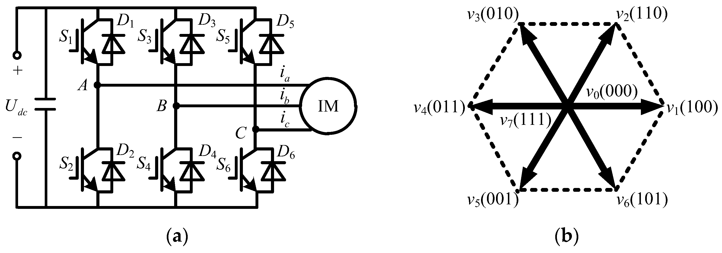
2. Inverter-Fed IM Mathematical Model

In α-β stationary frame, if the stator current is and stator flux ψs are selected as state variables, the mathematical model of IM can be described as follows.
d x d t = A x + B u s J d ω r d t = T e T L
where x = [is ψs]T is the state variable, us = [u u]T is the stator voltage vector, J is the moment of inertia, ωr is the rotor electrical angular speed, Te is the electromagnetic torque, TL is the load torque, and
A = 1 σ ( R s L s + R r L r ) + j ω r 1 σ ( R r L s L r j ω r L s ) R s 0 ,   B = 1 σ L s 1
where Rs is stator resistance, Rr is rotor resistance, Lm is mutual inductance, Ls is stator inductance, Lr is rotor inductance, and σ = 1 L m 2 / ( L s L r ) is the total leakage coefficient.
The electromagnetic torque can be expressed as follows.
T e = 1.5 N p I m ψ s i s
where Np is the number of pole pairs.
The IM drive system is shown in Figure 1. In this paper, a conventional two-level voltage source inverter (2L-VSI) is employed to supply the IM drive system, and its topology is described in Figure 1a. The eight fundamental VVs can be generated by 2L-VSI. Among them, v1~v6 are active VVs. v0 and v7 are the null VVs (vnull). In Figure 1a, the gate signals of the upper insulated-gate bipolar transistor (IGBT) are denoted by Sa, Sb, and Sc, such that 1 means ON and 0 means OFF. The fundamental VVs and switching states (Sa Sb Sc) are shown in Figure 1b. Using DC bus voltage Udc and switching states, all fundamental VVs can be reconstructed according to Equation (3).
u s α u s β = 2 3 U d c 1 1 2 1 2 0 3 2 3 2 S a S b S c T

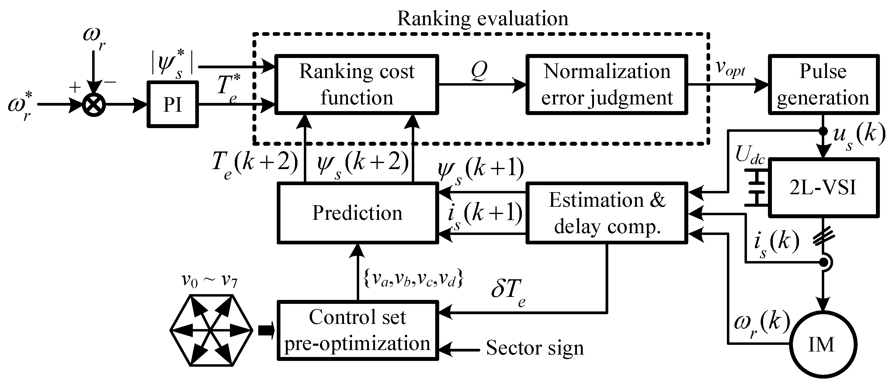
3. The Proposed Ranking-Based MPC Method

In this section, the proposed low-complexity ranking-based MPC is presented. Its diagram is shown in Figure 2. First, the prediction equation is described as the basis for the implementation of the proposed MPC algorithm. Based on the analysis of the candidate VV control effect, the candidate set pre-optimization is presented to simplify the ranking evaluation process. The prediction errors of torque and flux for candidate VVs are calculated and ranked. Then, the ranking cost function is designed to evaluate the ranking results of candidate VVs. Finally, the situation of simultaneous optimal ranking is discussed, and it improves the selection process of the optimal vector combined with the normalization error.

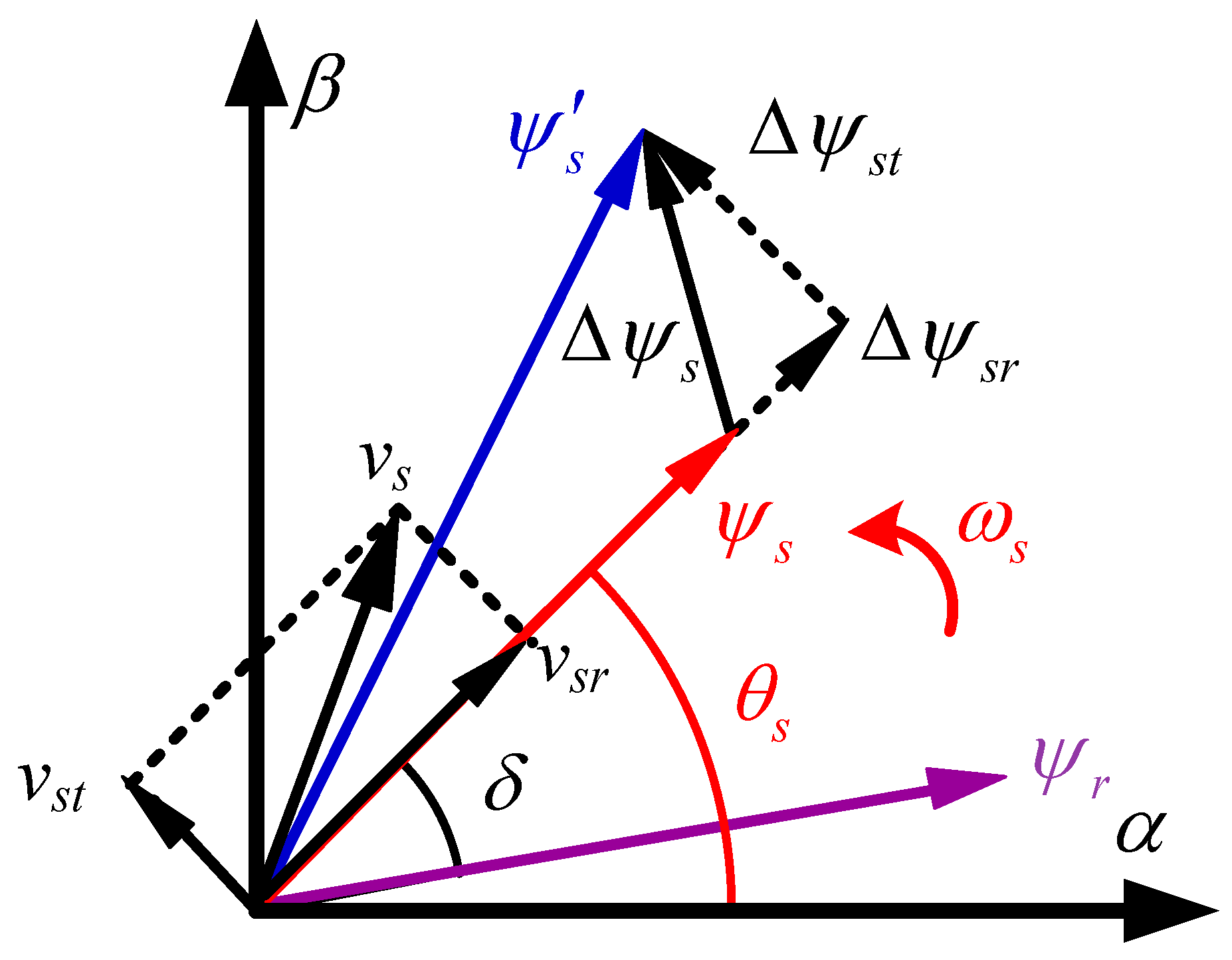
3.1. Prediction Equation

In the proposed MPC, the estimated value of stator flux is obtained by the full-order observer (FOB).
d x ^ d t = A x ^ + B u s + G ( i ^ s i s )
where x ^ = i ^ s ψ ^ s T are estimated state variables of stator current and stator flux and G is the feedback matrix.
G = ( a 1 ) ( R s σ L s + R r σ L r ) + j ( 1 a ) ω r ( a 2 1 ) R s T
The convergence speed and stability performance of the FOB can be guaranteed by configuring the feedback matrix of the observer [24]. In this paper, the poles of the FOB are configured to a = 1.2 times the poles of IM. Its configuration is similar to the classical form, which ensures it is effective and simple to implement [15].
To implement the prediction equation in a digital controller, it is necessary to perform discrete operations. The stator current and stator flux prediction values at k + 1 can be obtained by the first-order Euler formula.
ψ s ( k + 1 ) = ψ s ( k ) + T s u s ( k ) T s R s i s ( k )
i s ( k + 1 ) = ψ s ( k + 1 ) σ L s ψ s ( k ) σ L s ( 1 T s R r L r + j ω r ( k ) T s ) + ( 1 T s R r σ L r + j ω r ( k ) T s ) i s ( k )
where Ts is the control period.
The electromagnetic torque can be predicted as follows.
T e ( k + 1 ) = 1.5 N p I m { ψ s ( k + 1 ) i s ( k + 1 ) }

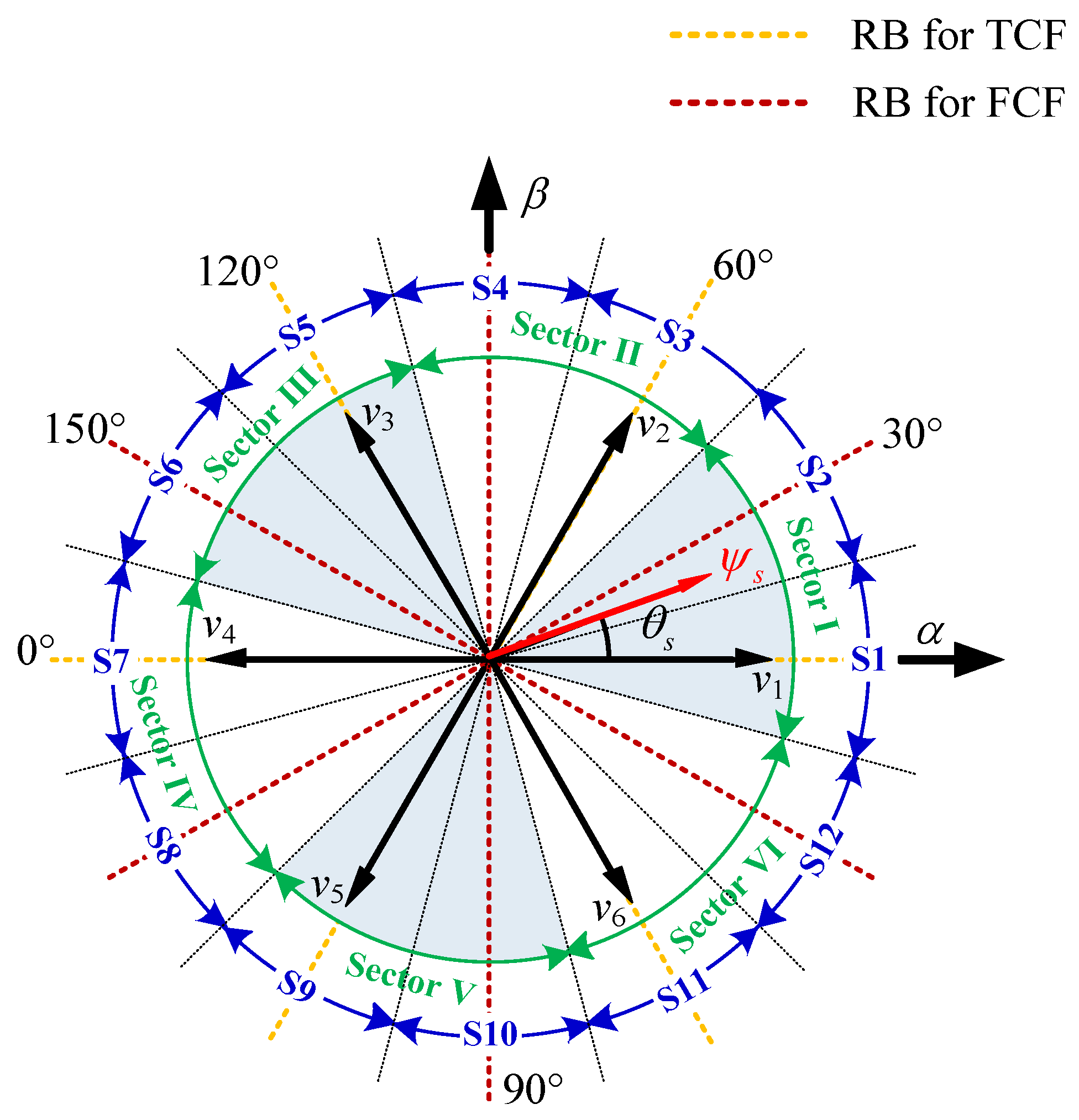
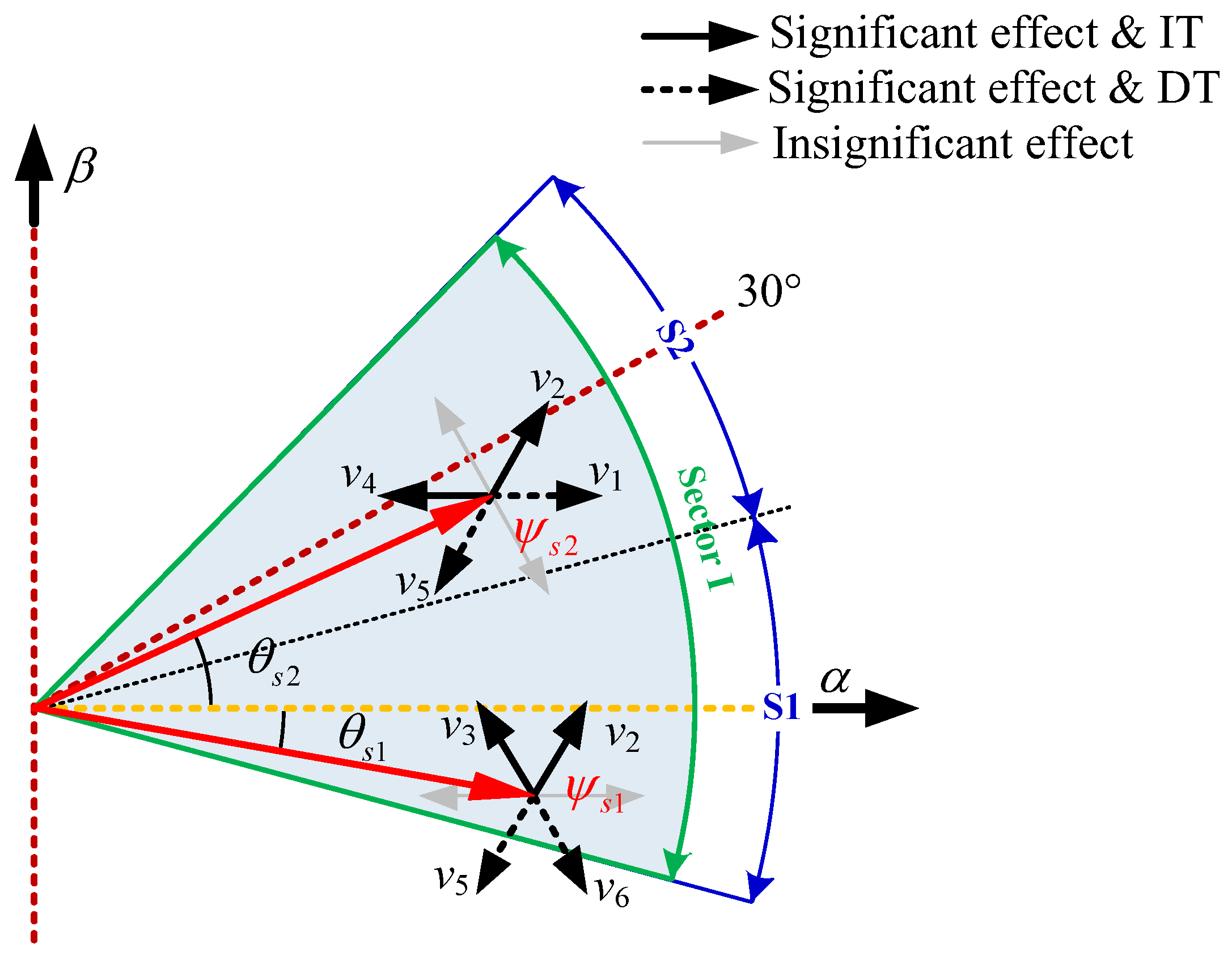
3.2. Control Set Pre-Optimization Principle

In the proposed method, control set pre-optimization is a necessary preparation for subsequent enumeration and ranking evaluation. To simplify the process of the optimal VV selection, the control set that originally covers all fundamental VVs can be pre-optimized based on the control effects of the torque and stator flux.
As shown in Figure 3, it is assumed that ψs is rotating in the counterclockwise direction at the speed of ωs. The rotor flux ψr lags it by the load angle δ. θs denotes the position of ψs. If stator resistance is ignored, vs can be decomposed into radial component vsr and tangential component vst along ψs.
v s = d | ψ s | d t e j θ s + j ω s | ψ s | = v s r + v s t
T e = 1.5 N p L m σ L s L r | ψ s | | ψ s | s i n δ
In Equation (9), the resulting vsr changes the flux magnitude, and vst changes the rotational speed of flux. Considering the changes caused by the above two components, combined with Equation (10), the torque can be controlled by selecting the appropriate VV. Given the significant degree of the VV control effect, the control effects of the six active VVs can be divided into significant effects and insignificant effects. Here, the significant effects refer to those that are available for both the torque and flux simultaneously, that is, increasing torque (IT) or decreasing torque (DT), and increasing flux magnitude (IF) or decreasing flux magnitude (DF). The insignificant effects mean that the change in the VV to at least one control objective is weak or ineffective. Thus, the torque deviation δTe and stator flux magnitude deviation δψs are defined.
δ T e = T e * T ^ e δ ψ s = | ψ s * | | ψ ^ s |
where T e * and ψ s * are the reference values of torque and stator flux. T e * is obtained by a speed proportional–integral (PI) controller.
The six active VVs are in pairs, and they can form three straight lines to divide the entire 360° plane equally. When ψs is rotated to some specific positions, the corresponding VV will completely lose its control effect on torque or flux amplitude changes. When θs = n1π/6 (n1 = 0, 2, 4), ψs is parallel to the three straight lines of the six active VVs, which can be described as the reference baselines (RBs) for torque control failure (TCF). The two corresponding VVs can only change the flux amplitude and fail to change the torque. When θs = n2π/6 (n2 = 1, 3, 5), ψs is perpendicular to the three straight lines, and they are described as the RBs for flux control failure (FCF). The corresponding VVs fail to change flux amplitude. As ψs turns away from the RBs, the associated insignificant effect gradually diminishes. In Figure 4, the entire plane is subdivided with the above RBs as the 30° sector centerline. Consequently, the 12 regions (S1~S12) can be obtained. In these regions, the corresponding active VVs are considered to have an insignificant effect.
The candidate set optimization is based on δTe for fast torque tracking since the torque is estimated based on both the stator flux and stator current, as seen in Equation (2). The VVs with significant effects are prioritized as candidate solutions.
For example, as shown in Figure 5, we only considered the situation that δTe > 0 to simplify the analysis, and the situation that δTe > 0 is similar. It is assumed that ψs1 is located in S1 (−15°~15°) at this moment, and the corresponding sector centerline is the 0° RB for TCF. In this region, v1 and v4 are not included in candidates according to the significant degree of the control effect. Due to the significant effects of v2 and v3, they are both considered candidates for IT, where v2 is for IF, and v3 is for DF. Similarly, when ψs is located in S2 (15°~45°), denoted by ψs2, the active VVs for candidates are v2 and v4.
Subsequently, a novel sector distribution (Sector I~Sector VI) is presented by integrating two adjacent subdivided regions. The corresponding candidate VVs are also integrated. Each such sector contains an RB for TCF and FCF, respectively. Accordingly, the six sectors in this paper can be defined as follows.
( 4 N 5 ) π / 12 Θ ( N ) ( 4 N 1 ) π / 12
where Θ is the sector and N = 1, …, 6.
According to the sector sign, the optimized candidate set {va, vb, vc, vd} can be obtained combined with the torque deviation sign. For the four candidate elements mentioned above, va is the preferred VV shared by the two merge regions, which has significant effects on the whole sector. vb and vc are the secondary preferred VVs. They only have a significant effect on their respective subdivided region, while their effects are insignificant for the other regions. These two VVs, which have insignificant effects, are intended to correct the excessive exclusion of feasible solutions. Considering the situation of δTe = 0 or δψs = 0, a null VV is employed as the supplemental VV to reduce torque and flux ripples effectively. For this reason, vd is locked as vnull.
When δTe > 0, the candidate set for all of Sector I is {v2, v3, v4, vnull}. Among these VVs, v2 is the preferred VV for IT, and it has a significant effect on both S1 and S2. v3 and v4 are the secondary preferred VVs to avoid excessively excluding candidate VVs during the optimization process. It is noted that v5 and v6 are VVs for DT, and their application makes torque fail to track the reference. This leads to a large torque error. Therefore, v5 and v6 are not feasible solutions based on the presented pre-optimization principle. The four candidate VVs strive to provide sufficient control degrees of freedom. The analysis of the other sectors and conditions is similar to that of Sector I. Based on the above principle, the optimization results are summarized in Table 1.
After pre-optimization, only four VVs need to be evaluated in the proposed MPC. Compared to conventional MPTC, the candidates are reduced by nearly half, which can significantly reduce the computational cost. Furthermore, due to the pre-optimization principle based on δTe, the redundant candidates with obvious incorrect trends are excluded, which are absolutely impossible to be the optimal solution for torque control. This prevents partial redundant VVs from disrupting the subsequent ranking evaluation.

3.3. Cost Function Design

In conventional MPTC, the cost function enumerates all fundamental VVs to obtain the optimal VV. The prediction errors can be obtained according to the predicted torque and flux. In addition, considering the average switching frequency reduction, a switching penalty term can be defined.
J s w = x = { a , b , c } | [ S x ( k + 1 ) ] i S x ( k ) |
where [Sx(k + 1)]i is the switching state corresponding to the current enumerated VV at k + 1, i is the index of enumerated VVs, and Sx(k) is the applied switching state of 2L-VSI at k.
By combining prediction errors and switching frequency, the cost function of conventional MPTC is usually designed as follows.
J = | T e * T e ( k + 1 ) | + k f | | ψ s * | | ψ s ( k + 1 ) | | + k s w J s w
where kf is the weighting factor of the flux penalty term, and ksw is the weighting factor of the switching penalty term.
The weighting factors are used to modify the weighting relationship of the torque, flux, and switching frequency. However, the tuning work is cumbersome, and inappropriate tuning can deteriorate the system control performance.
To avoid tedious weighting factor tuning, the proposed MPC adopts a ranking method to evaluate the candidate VVs and achieve multi-objective optimization. Considering the delay compensation [5], the prediction errors of the torque and flux can be calculated, respectively, as follows.
J 1 = | T e * T e ( k + 2 ) |
J 2 = | | ψ s * | | ψ s ( k + 2 ) | |
Subsequently, it is necessary to rank the results of Equations (15) and (16). This process essentially transforms the evaluation of the torque and flux from the quantitative level to the ranking level.
J 1 ( v n ) r 1 ( v n )
J 2 ( v n ) r 2 ( v n )
The rankings obtained by the corresponding candidate VVs need to be recorded. The lower ranking means fewer resulting control errors. The optimal VV (vopt) should have a relatively low ranking for both the torque and flux among all candidates. In the proposed method, the ranking optimization is performed by minimizing the comprehensive ranking evaluation as follows.
v o p t = arg min { v a , v b , v c , v d } [ r 1 2 ( v n ) + r 2 2 ( v n ) ]
It is worth noting that the proposed method takes into account the reduction in the switching frequency when setting the candidate elements. Due to the previous pre-optimization of the control set, if the torque deviation sign is the same, the candidate VVs in the control set have adjacent switching states, which is beneficial for reducing the switching frequency of power devices. The penalty term Jsw in conventional MPTC is not necessary for the proposed method. This is also a potential benefit of the presented control set pre-optimization. Accordingly, the switching frequency does not need to be evaluated separately for ranking, which can further reduce the computational burden. Considering the case where vopt is a null VV, for the sake of reducing the switching frequency, if the applied optimal VV in the last control period is one of (001), (010), (100), or (000), vopt should be (000). Otherwise, it should be (111).

3.4. Optimal Solution Decision-Making

By converting the quantization errors of multi-objective control into rankings, although the weighting factors are eliminated, the above process results in a partial loss of the quantization evaluation information. For the cost function of conventional MPTC, its evaluation results can theoretically be taken from a non-negative real number set. However, after introducing the ranking method, its calculation results can only be elements from a finite positive integer point set. The scope of categories for the evaluation results is significantly decreased after ranking. This greatly increases the probability of multiple ranking results being simultaneously optimal. In such a situation, the quantity of feasible solutions corresponding to simultaneous optimal ranking, denoted by Q, is no longer 1. This emergence of the simultaneous optimal ranking means that the optimal VV cannot be uniquely and effectively determined at the ranking level. In addition, the same ranking evaluation results may vary greatly in quantization error, which affects the control performance. Hence, different from the conventional MPTC, the ranking-based MPC should consider the simultaneous optimal ranking to further enhance the control performance.
To improve the optimal solution decision-making process, the cost function in the proposed MPC is designed based on the 2-norm ranking, which effectively reduces the occurrence of simultaneous optimal ranking. Despite this, if the evaluation results are 5, 10, or 13, the simultaneous optimal situation could still happen. In such a situation, multiple candidate solutions can simultaneously minimize the ranking cost function, which confuses the optimal VV selection. To this end, the proposed MPC reconsidered the quantization errors of the two potential optimal solutions. The proposed method introduces normalization errors to avoid inaccurate evaluation caused by the difference in the error range of the torque and flux. To achieve normalization, the minimum error min(Ji) and the maximum error max(Ji) need to be registered during the sorting process. The normalized error for vn can be calculated as follows.
e i ( v n ) = J i ( v n ) min ( J i ) max ( J i ) min ( J i )
where Ji is the uniformly expressed prediction error, i = 1 is dedicated to the torque error, and i = 2 is dedicated to the stator flux error.
For the candidates with simultaneous optimal ranking, the VV that minimizes Equation (20) is selected as the optimal one. In this way, the quantization error evaluation is re-enabled when the ranking evaluation fails. There is no fixed priority between J1 and J2, which is to achieve a relatively fair evaluation. Additionally, due to previous pre-optimization, the maximum Q does not exceed 2, so it reduces the complexity of solving the simultaneous optimal ranking. Therefore, even if the simultaneous optimal ranking is considered, the computational complexity of the proposed MPC is still substantially reduced compared to the previous methods of enumerating all VVs.

3.5. Control Flow Description

According to the previously described control structure, the proposed control strategy flow can be summarized into the following steps:
  • Measure is(k), Udc(k), and ωr(k).
  • Estimate is(k + 1) and ψs(k + 1).
  • Determine the sector sign, and generate candidate VVs based on the control set pre-optimization principle.
  • Predict ψs(k + 2) and Te(k + 2). Calculate the prediction errors of torque and flux. Perform ranking evaluation, and lock the VV of the minimum ranking cost function.
  • Judge whether there is a simultaneous optimal situation. If Q = 1, go directly to the next step. Otherwise, solve the normalized error to finalize the optimal VV.
  • Select and apply the optimal VV.

4. Results and Discussion

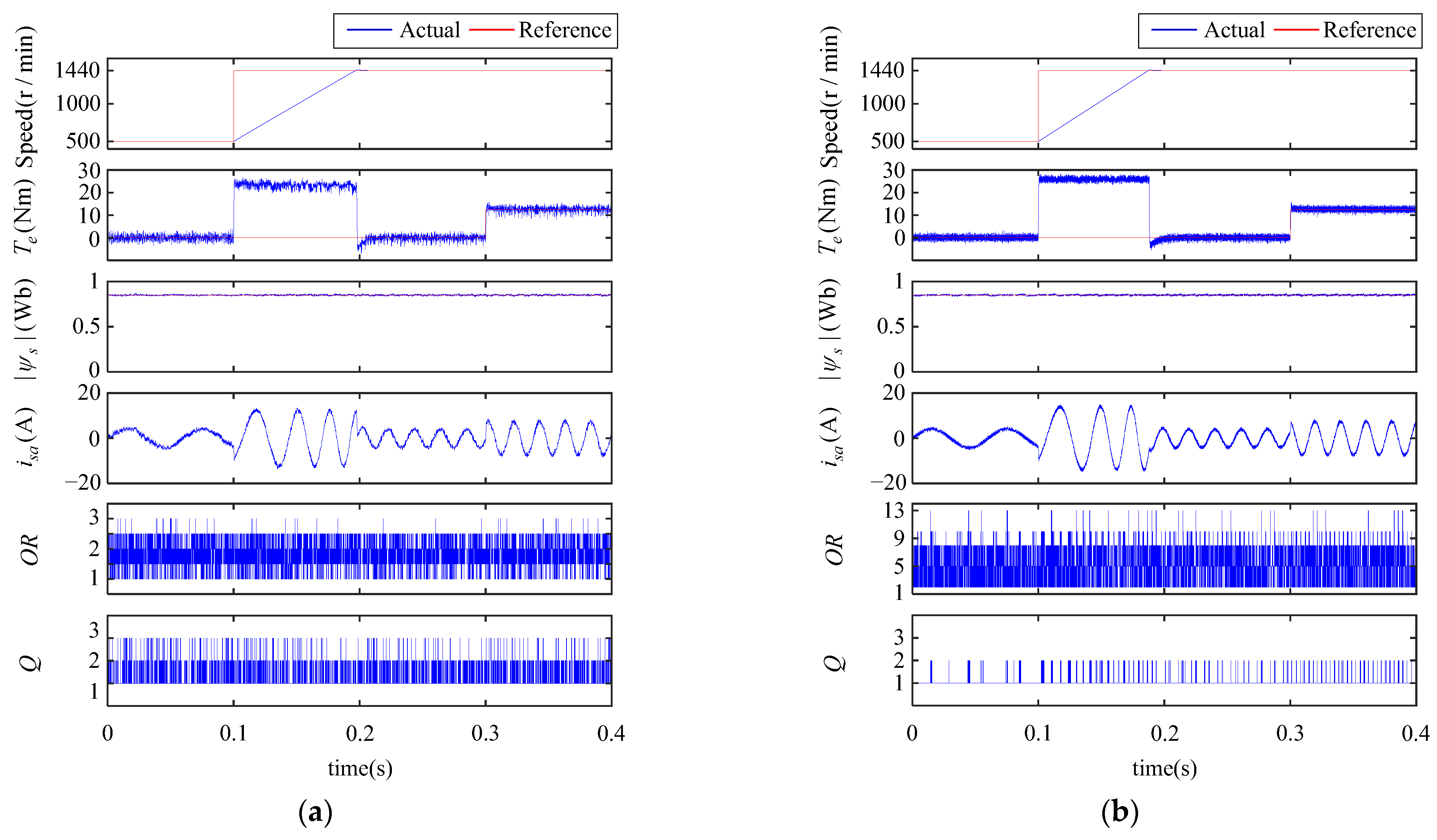
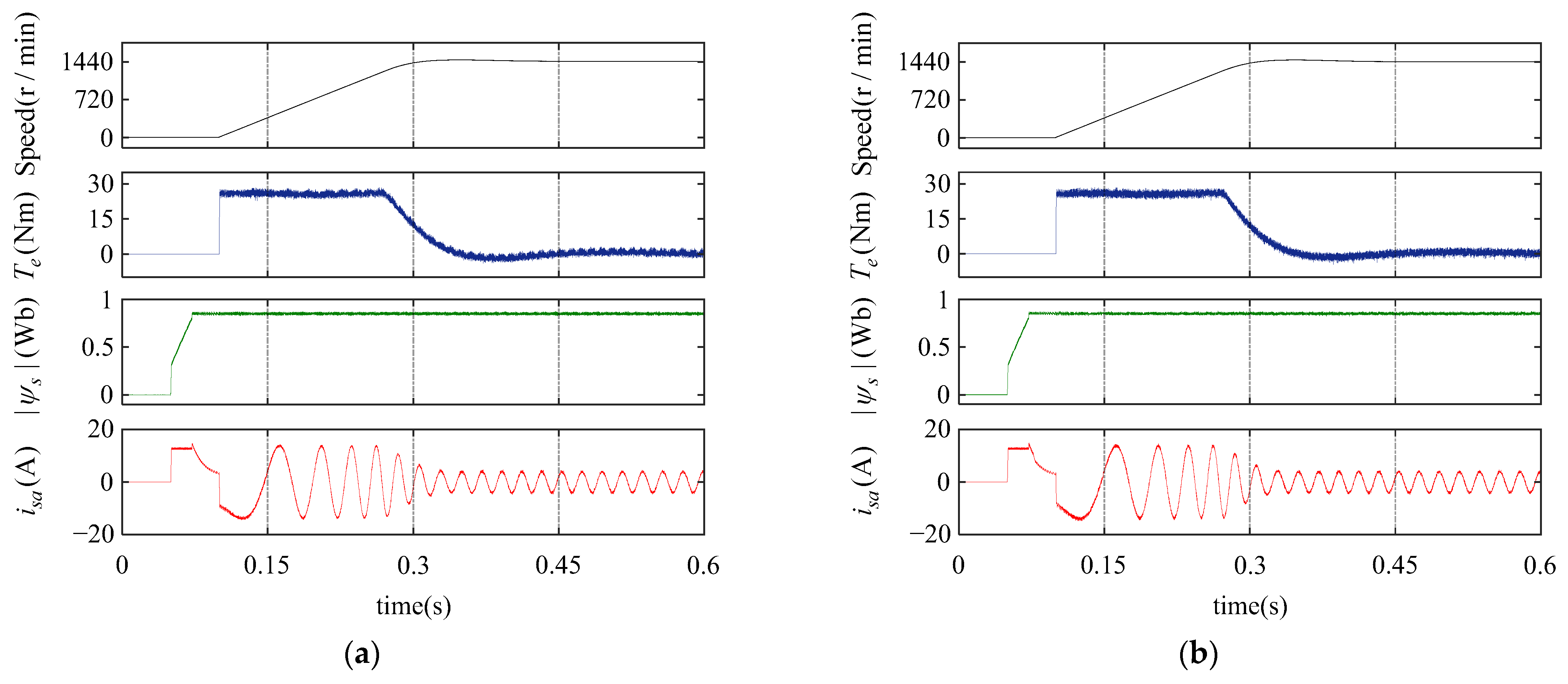
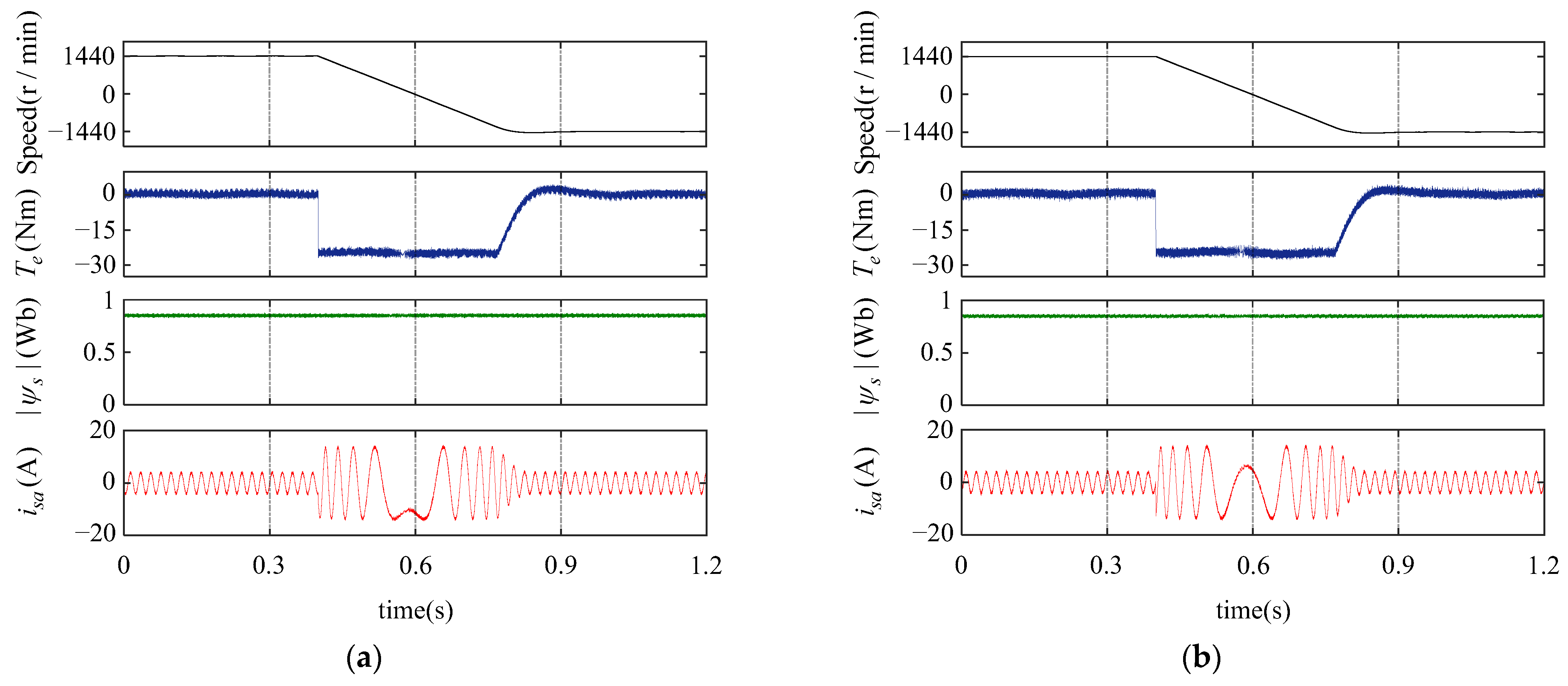
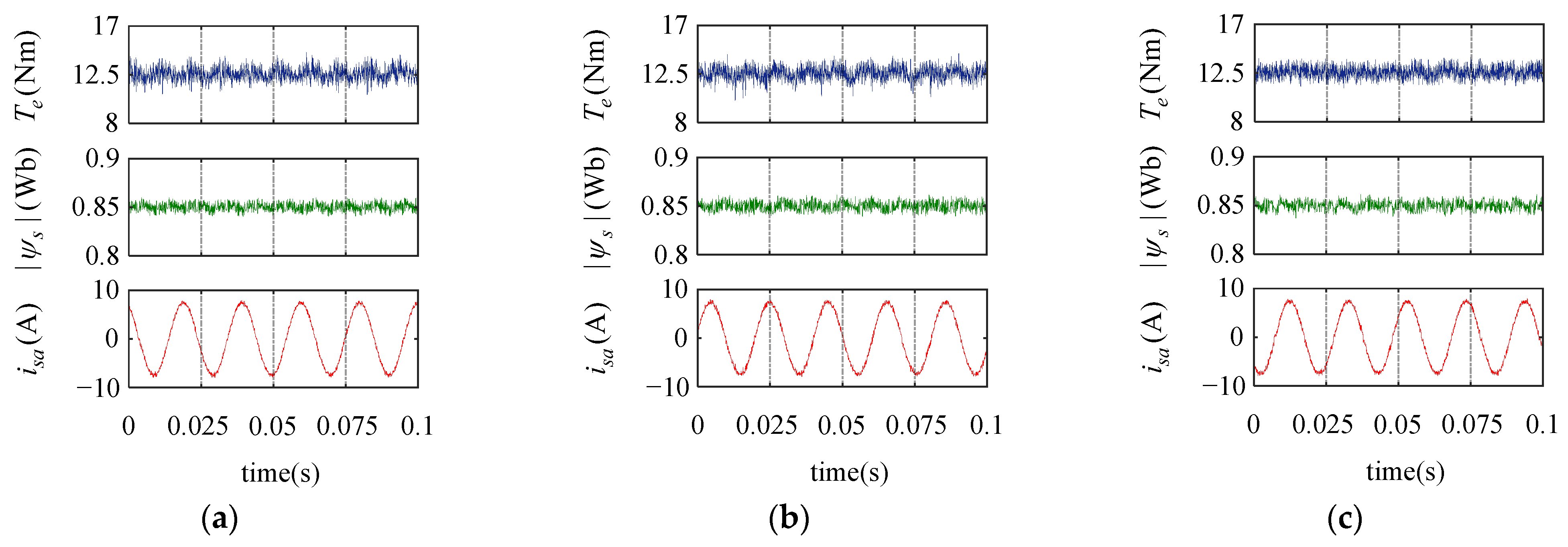
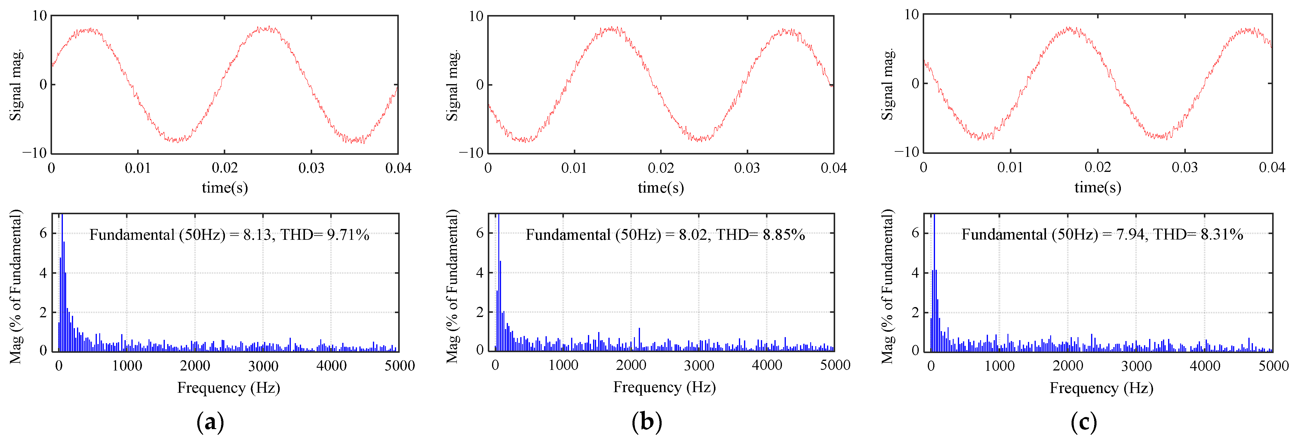
4.1. Simulation Verification

In the environment of MATLAB/Simulink, the proposed MPC was verified using simulation. Table 2 shows the IM parameters. Simulation comparisons are presented between the average ranking-based MPC [17] and the proposed MPC.
The simulation results include the speed, torque, stator flux amplitude, and stator current. The optimal ranking results (OR) and Q were also obtained to investigate simultaneous optimal ranking situations. Initially, the IM ran at 500 r/min with no-load. From 0.1 s, the IM accelerated to 100% nominal speed, then suddenly increased to 12.5 Nm at 0.3 s. As shown in Figure 6, both methods could be rapidly adjusted to the reference without excessive overshoot. Compared to the conventional ranking-based method, the proposed method performed significantly lower torque ripple.
The weighting factors have been eliminated in the ranking-based methods, but both MPCs suffer from the situation of simultaneous optimal ranking. According to the optimal ranking results, the simultaneous optimal situation happens for both methods, which is consistent with the previous analysis. Based on the results of the OR, the proposed MPC effectively reduced the occurrence of simultaneous optimal ranking. Although it did not completely avoid the occurrence of simultaneous optimal ranking, the proposed method further determined the optimal VV according to the principle of minimum normalized error. If a simultaneous optimal situation occurs, the number of VVs that the proposed method needs to evaluate is lower than that of the conventional method. Hence, the proposed method has lower computational complexity.

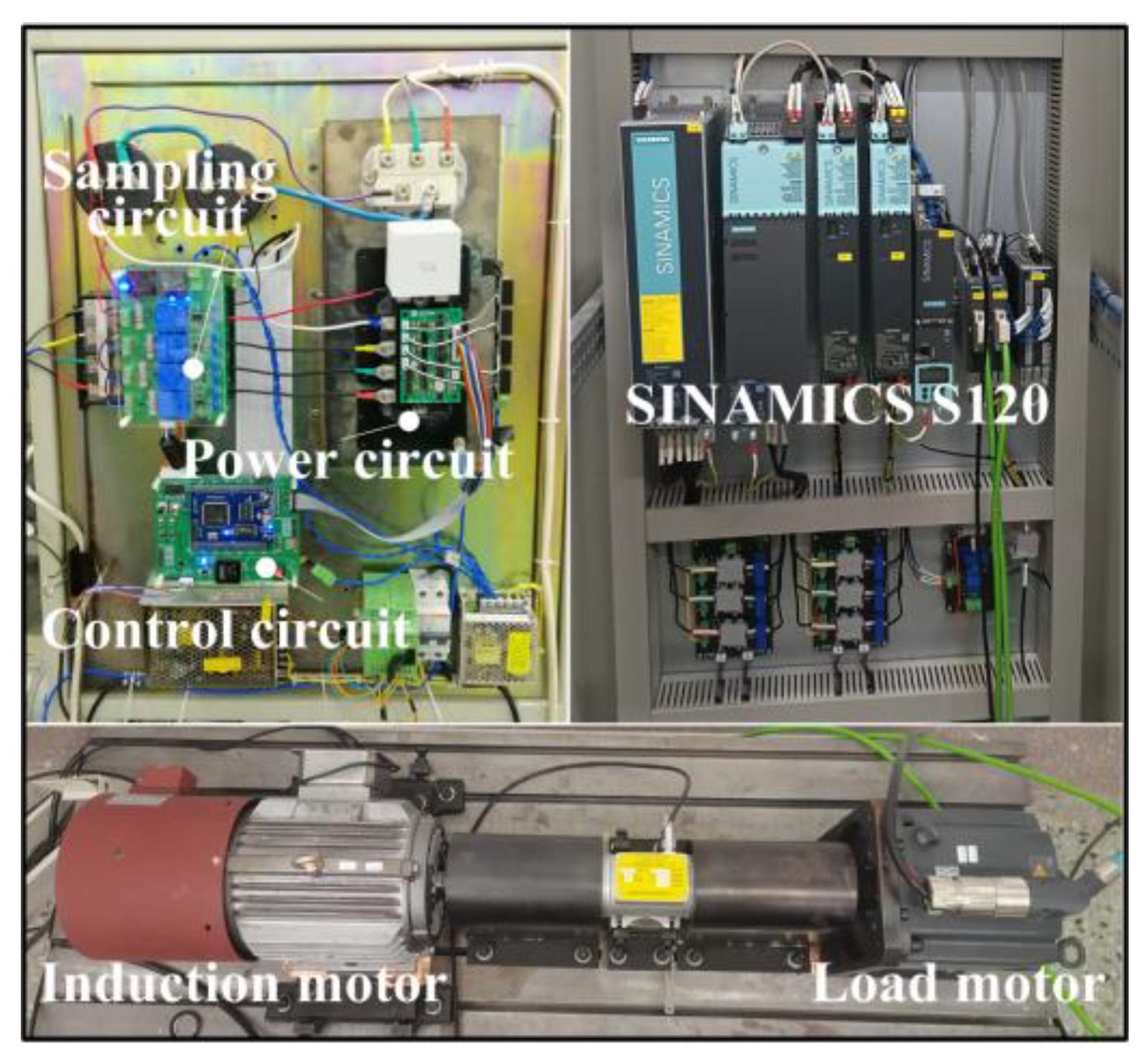
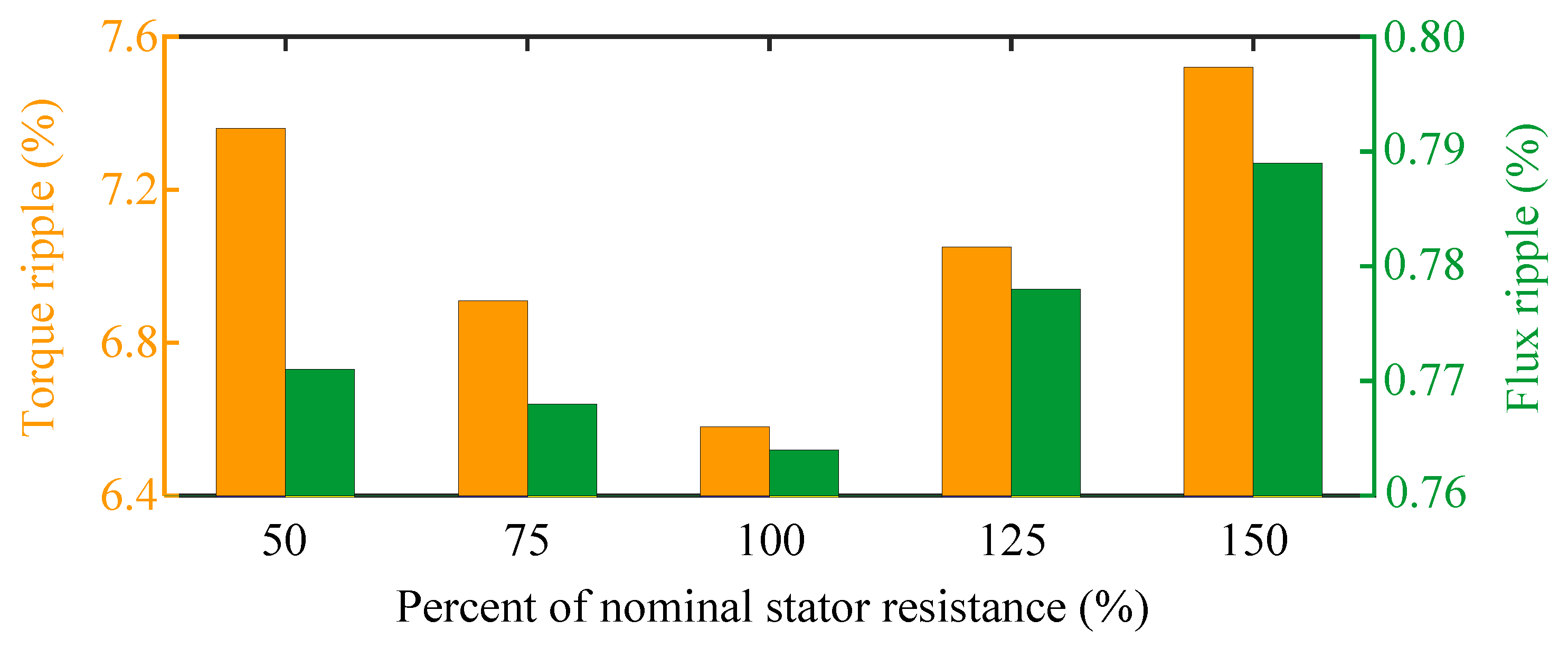
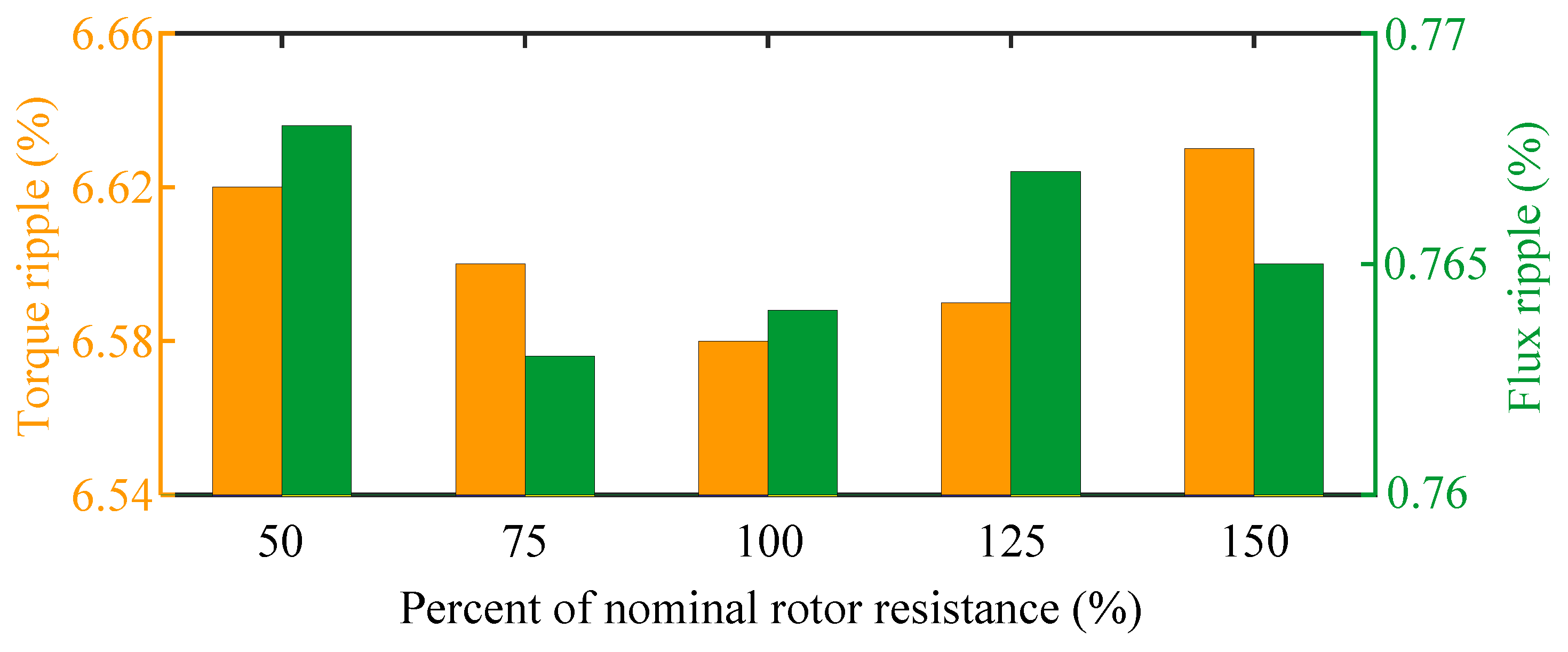
4.2. Analysis of Experimental Results

Further experimental verifications of the proposed MPC were carried out by a real IM drive platform, as shown in Figure 7.
In the platform, a 4 kW IM was used as the test motor, and the IM parameters are consistent with Table 2. The DSP TMS320F28335 (Texas Instruments, Dallas, TX, USA) was used to execute the control algorithms, and PM50RL1A060 of Mitsubishi (Mitsubishi, Tokyo, Japan) was chosen as the power module. The load motor was controlled by a Siemens SINAMICS S120 converter (Siemens, Munich, Germany). The DL750 digital oscilloscope (Yokogawa, Musashino, Japan) was used to record the results.
In the experimental tests, the conventional MPTC [5] and average ranking-based MPC [17] were used as the comparison methods for the proposed low-complexity ranking-based MPC. The same gain for the speed PI controller was employed for all MPC methods. The sampling frequency was set to 15 kHz.
Comparison tests between the conventional MPTC and the proposed MPC were implemented to evaluate their dynamic performance, including a starting acceleration test and speed reversal test. To prevent overcurrent during start-up, the scheme of pre-excitation was employed. The dynamic starting acceleration response from standstill to rated speed was tested, as shown in Figure 8. After pre-excitation, the proposed MPC rapidly accelerated to 100% nominal speed with maximum torque. In the absence of excessive overshoot, the proposed MPC achieved fast starting acceleration performance. The acceleration time and adjustment time of both methods were close.
The experimental results of the speed reversal operation are presented in Figure 9. Initially, the motor operated with a forward 100% nominal speed with no-load. Subsequently, the speed reference was set to a backward 100% nominal speed as a step change. The proposed MPC maintained a rapid speed reversal response similar to conventional MPTC. Compared to the conventional MPTC, the proposed MPC did not degrade the dynamic performance of the drive system, and it simplified the enumeration process without the weighting factor.
Comparison tests among conventional MPTC, average ranking-based MPC, and proposed MPC were implemented to evaluate their steady-state performance. Under the conditions of 1440 r/min and 12.5 Nm, the experimental results of the torque, stator flux amplitude, and a-phase stator current were obtained, as shown in Figure 10. In terms of torque control, the proposed MPC performed lower torque ripple than the conventional MPTC and average rank-based MPC. The control set pre-optimization in the proposed MPC was designed based on torque deviation, which gives higher priority to torque control. The comparison results indicate that the optimization was effective. In terms of flux control, the three methods exhibited similar results for flux ripple.
Figure 11 shows the results of the stator current and corresponding harmonic spectrums for the three methods. The proposed MPC provided the lowest total harmonic distortion (THD), which illustrates its improvement in current control performance. For the ease of quantifying the steady-state performance, M is calculated to characterize the average ripple in this study.
M = 1 n i = 1 n ( M i M ¯ )
where M ¯ is the sample average and n is the number of sampling data points.
The quantification results are presented in Table 3, including the torque ripple, stator flux ripple, stator current THD, and average switching frequency (fav). Compared to the average ranking-based method, when facing simultaneous optimal ranking situations, the proposed VV selection mechanism based on the normalized error may select different candidate solutions. The relatively lower torque ripples and current harmonics indicate that this optimal solution decision-making is beneficial for improving steady-state performance. In addition, the proposed MPC presented a lower average switching frequency at the same sampling frequency. According to the results of the control set pre-optimization in Table 1, the candidate active VVs of the same sector were adjacent. When the flux vector lies in the adjacent or same sector, if the torque deviation has the same sign, switching may occur between two adjacent or identical active VVs. As a result, the average switching frequency is reduced. The above results show that the improvements in the proposed MPC are effective. The proposed method can achieve good steady-state performance while eliminating the adjustment of the weighting factor.
The computational costs of the three MPC methods are presented in Table 4. In the comparison, all MPC algorithms adopt the same FOB for stator flux observation, so the time consumption caused by the observation is not included in the presented execution time. In this study, the execution time of the MPC algorithm was obtained by enabling a control signal to 1 at the beginning of the algorithm, and then setting it to 0 at the end of the algorithm. The ranking-based approach is effective in solving multi-objective optimization problems of MPC, and its optimization process does not involve the tedious tuning of the weighting factors. However, the ranking evaluation process also increases the computational cost. For conventional average ranking-based MPC, additional optimization sorting algorithms need to be introduced to ensure its implementation at a high sampling frequency. Despite the introduction of the divide-and-conquer quicksort [17], the execution time of the average ranking-based MPC was still significantly increased compared to the conventional MPTC, as shown in Table 4. Due to the presented pre-optimization, the number of candidates in the proposed MPC was reduced, and they were nearly half of that in the conventional MPTC and average ranking-based MPC. Although the stator flux position operation is required, the program execution time is very short. Furthermore, the proposed method does not require a complex sorting algorithm. Hence, the proposed method achieves an efficient MPC with a low computational cost.
The parameter mismatch test was performed to evaluate the parameter sensitivity of the proposed MPC. At IM operating conditions of 720 r/min and 12.5 Nm, the stator resistance and rotor resistance varied within ± 50% of their nominal values. The obtained results of the stator resistance variation are shown in Figure 12. As the stator resistance changed from 50% to 150% nominal, it increased the torque and flux ripple, but not by much. Compared to the influence on torque, underestimation of the stator resistance had a weaker effect on the flux ripple. In addition, rotor resistance variation had little influence on the proposed strategy, as shown in Figure 13. The proposed MPC shows more robustness to rotor resistance variation.

5. Conclusions

In the field of marine electric power propulsion, the significance of high-performance electric motor drive technology cannot be overstated. A promising avenue to enhance the functionality of drives lies in the realm of multi-objective optimization of motor operations. This paper suggests a low-complexity, ranking-based model predictive control (MPC) approach for induction motor (IM) drives, aiming to achieve effective multi-objective optimization without the need for weighing factors. The proposed method, guided by the pre-optimization principle of the control set, effectively reduces the number of candidates, contributing to a streamlined and efficient approach. Considering the simultaneous optimal ranking situation, the proposed ranking evaluation combined with normalized error optimizes the optimal solution decision-making process. The simulation and experimental results show that the proposed MPC is effective. The proposed MPC presents a similar dynamic performance as conventional MPTC, and has good steady-state performance. In the case of resistance mismatch, it exhibits strong parameter robustness. Without tuning the weighting factors, the proposed method achieved benefits in reducing the torque ripple and average switching frequency. Based on the above contributions, the proposed MPC can be considered as a competitive alternative to traditional MPTC. In addition, the reduction in computational burden may contribute to the research of MPC methods combined with online identification and observation techniques for IM drives in marine propulsion systems.

Author Contributions

Conceptualization, T.L. and X.Y.; methodology, T.L. and J.K.; validation, T.L.; formal analysis, T.L. and J.K.; investigation, J.K.; resources, T.L. and X.Y.; data curation, T.L.; writing—original draft preparation, T.L. and X.Y.; writing—review and editing, T.L. and J.K.; visualization, T.L.; supervision, X.Y.; project administration, T.L. and X.Y.; funding acquisition, X.Y. All authors have read and agreed to the published version of the manuscript.

Funding

This research was funded by the Natural Science Foundation of Heilongjiang Province of China (Grant number LH2021E037), and the Zhejiang Province Basic Public Welfare Research Program (Grant number LGG22E070001).

Institutional Review Board Statement

Not applicable.

Informed Consent Statement

Not applicable.

Data Availability Statement

Data are contained within the article.

Conflicts of Interest

The authors declare no conflicts of interest.

References

  1. Geertsma, R.D.; Negenborn, R.R.; Visser, K.; Hopman, J.J. Design and Control of Hybrid Power and Propulsion Systems for Smart Ships: A Review of Developments. Appl. Energy 2017, 194, 30–54. [Google Scholar] [CrossRef]
  2. Han, X.; Yao, X.L.; Liao, Y.F. Full Operating Range Optimization Design Method of LLC Resonant Converter in Marine DC Power Supply System. J. Mar. Sci. Eng. 2023, 11, 2142. [Google Scholar] [CrossRef]
  3. Bai, H.; Yu, B.; Gu, W. Full Research on Position Sensorless Control of RDT Motor Based on Improved SMO with Continuous Hyperbolic Tangent Function and Improved Feedforward PLL. J. Mar. Sci. Eng. 2023, 11, 642. [Google Scholar] [CrossRef]
  4. Ma, C.W.; Rodríguez, J.; Garcia, C.; De Belie, F. Integration of Reference Current Slope Based Model-Free Predictive Control in Modulated PMSM Drives. IEEE J. Emerg. Sel. Top. Power Electron. 2023, 11, 1407–1421. [Google Scholar] [CrossRef]
  5. Miranda, H.; Cortés, P.; Yuz, J.I.; Rodríguez, J. Predictive Torque Control of Induction Machines Based on State-Space Models. IEEE Trans. Ind. Electron. 2009, 56, 1916–1924. [Google Scholar] [CrossRef]
  6. Buja, G.S.; Kazmierkowski, M.P. Direct Torque Control of PWM Inverter-fed AC Motors—A Survey. IEEE Trans. Ind. Electron. 2004, 51, 744–757. [Google Scholar] [CrossRef]
  7. Davari, S.A.; Khaburi, D.A.; Kennel, R. An Improved FCS–MPC Algorithm for an Induction Motor with an Imposed Optimized Weighting Factor. IEEE Trans. Power Electron. 2012, 27, 1540–1551. [Google Scholar] [CrossRef]
  8. Gong, C.; Hu, Y.H.; Ma, M.Y.; Gao, J.Q.; Shen, K. Novel Analytical Weighting Factor Tuning Strategy Based on State Normalization and Variable Sensitivity Balance for PMSM FCS-MPTC. IEEE/ASME Trans. Mechatronic. 2020, 25, 1690–1694. [Google Scholar] [CrossRef]
  9. Novak, M.; Xie, H.T.; Dragicevic, T.; Wang, F.X.; Rodríguez, J.; Blaabjerg, F. Optimal Cost Function Parameter Design in Predictive Torque Control (PTC) Using Artificial Neural Networks (ANN). IEEE Trans. Ind. Electron. 2021, 68, 7309–7319. [Google Scholar] [CrossRef]
  10. Rojas, C.A.; Rodríguez, J.; Kouro, S.; Villarroel, F. Multiobjective Fuzzy-Decision-Making Predictive Torque Control for an Induction Motor Drive. IEEE Trans. Power Electron. 2017, 32, 6245–6260. [Google Scholar] [CrossRef]
  11. Geyer, T. Algebraic tuning guidelines for model predictive torque and flux control. IEEE Trans. Ind. Appl. 2018, 51, 4464–4475. [Google Scholar] [CrossRef]
  12. Muddineni, V.P.; Bonala, A.K.; Sandepudi, S.R. Grey Relational Analysis-Based Objective Function Optimization for Predictive Torque Control of Induction Machine. IEEE Trans. Ind. Appl. 2021, 57, 835–844. [Google Scholar] [CrossRef]
  13. Yang, A.X.; Lu, Z.G. Multiscalar Model-Based Predictive Torque Control without Weighting Factors and Current Sensors for Induction Motor Drives. IEEE J. Emerg. Sel. Top. Power Electron. 2022, 10, 5785–5797. [Google Scholar] [CrossRef]
  14. Zhang, X.G.; Yan, K.; Cheng, M. Two-Stage Series Model Predictive Torque Control for PMSM Drives. IEEE Trans. Power Electron. 2021, 36, 12910–12918. [Google Scholar] [CrossRef]
  15. Wu, X.; Huang, W.X.; Lin, X.G.; Jiang, W.; Zhao, Y.; Zhu, S.F. Direct Torque Control for Induction Motors Based on Minimum Voltage Vector Error. IEEE Trans. Ind. Electron. 2021, 68, 3794–3804. [Google Scholar] [CrossRef]
  16. Kodumur Meesala, R.E.; Kunisetti, V.P.K.; Kumar Thippiripati, V. Enhanced Predictive Torque Control for Open End Winding Induction Motor Drive Without Weighting Factor Assignment. IEEE Trans. Power Electron. 2019, 34, 503–513. [Google Scholar] [CrossRef]
  17. Rojas, C.A.; Rodríguez, J.; Villarroel, F.; Espinoza, J.R.; Silva, C.A.; Trincado, M. Predictive Torque and Flux Control Without Weighting Factors. IEEE Trans. Ind. Electron. 2013, 60, 681–690. [Google Scholar] [CrossRef]
  18. Kusuma, E.; Eswar, K.M.R.; Vinay Kumar, T. An Effective Predictive Torque Control Scheme for PMSM Drive Without Involvement of Weighting Factors. IEEE J. Emerg. Sel. Top. Power Electron. 2021, 9, 2685–2697. [Google Scholar] [CrossRef]
  19. Norambuena, M.; Rodríguez, J.; Zhang, Z.B.; Wang, F.X.; Garcia, C.; Kennel, R. A Very Simple Strategy for High-Quality Performance of AC Machines Using Model Predictive Control. IEEE Trans. Power Electron. 2019, 34, 794–800. [Google Scholar] [CrossRef]
  20. Xia, C.L.; Liu, T.; Shi, T.N.; Song, Z.F. A Simplified Finite-Control-Set Model-Predictive Control for Power Converters. IEEE Trans. Ind. Informat. 2014, 10, 991–1002. [Google Scholar]
  21. Habibullah, M.; Lu, D.D.; Xiao, D.; Rahman, M.F. A Simplified Finite-State Predictive Direct Torque Control for Induction Motor Drive. IEEE Trans. Ind. Electron. 2016, 63, 3964–3975. [Google Scholar] [CrossRef]
  22. Mamdouh, M.; Abido, M.A. Efficient Predictive Torque Control for Induction Motor Drive. IEEE Trans. Ind. Electron. 2019, 66, 6757–6767. [Google Scholar] [CrossRef]
  23. Geyer, T. Computationally Efficient Model Predictive Direct Torque Control. IEEE Trans. Power Electron. 2011, 26, 2804–2816. [Google Scholar] [CrossRef]
  24. Davari, S.A.; Rodríguez, J. Predictive Direct Voltage Control of Induction Motor with Mechanical Model Consideration for Sensorless Applications. IEEE J. Emerg. Sel. Top. Power Electron. 2018, 6, 1990–2000. [Google Scholar] [CrossRef]
Figure 1. The IM drive system. (a) The topology of the inverter-fed IM drive system. (b) The distribution of fundamental VVs.
Jmse 12 00378 g001
Figure 2. The proposed MPC diagram.
Jmse 12 00378 g002
Figure 3. Description of voltage vector decomposition.
Jmse 12 00378 g003
Figure 4. Sector distribution of the presented pre-optimization principle.
Jmse 12 00378 g004
Figure 5. Detailed description of Sector I.
Jmse 12 00378 g005
Figure 6. Simulation results. (a) Average ranking-based MPC. (b) Proposed MPC.
Jmse 12 00378 g006
Figure 7. Experimental platform of the IM control system.
Jmse 12 00378 g007
Figure 8. Experimental results of the starting acceleration operation. (a) Conventional MPTC. (b) Proposed MPC.
Jmse 12 00378 g008
Figure 9. Experimental results of the speed reversal operation. (a) Conventional MPTC. (b) Proposed MPC.
Jmse 12 00378 g009
Figure 10. Experimental results of steady-state performance. (a) Conventional MPTC. (b) Average ranking-based MPC. (c) Proposed MPC.
Jmse 12 00378 g010
Figure 11. Harmonic spectrum of the stator current. (a) Conventional MPTC. (b) Average ranking-based MPC. (c) Proposed MPC.
Jmse 12 00378 g011
Figure 12. Analysis of parameter sensitivity considering stator resistance variation.
Jmse 12 00378 g012
Figure 13. Analysis of parameter sensitivity considering rotor resistance variation.
Jmse 12 00378 g013
Table 1. Control set pre-optimization.
Sector SignCandidate Elements (δTe > 0/δTe < 0)
Preferred VV (va)Secondary Preferred VVs (vb, vc)
Iv2/v5(v3, v4)/(v6, v1)
IIv3/v6(v4, v5)/(v1, v2)
IIIv4/v1(v5, v6)/(v2, v3)
IVv5/v2(v6, v1)/(v3, v4)
Vv6/v3(v1, v2)/(v4, v5)
VIv1/v4(v2, v3)/(v5, v6)
Table 2. The tested IM parameters.
ParameterValue
Rated power PN4 kW
Rated speed nN1440 r/min
DC bus voltage Udc540 V
Rated frequency fn50 Hz
Stator resistance Rs0.922 Ω
Rotor resistance Rr0.821 Ω
Mutual inductance Lm0.162 H
Stator inductance Ls0.170 H
Rotor inductance Lr0.170 H
Number of pole pairs Np2
Table 3. Quantification results of steady-state performance.
MethodConventional MPTCRanking-Based MPCProposed MPC
Torque ripple (Nm)0.6373850.6212280.588231
Flux ripple (Wb)0.0081340.0086680.008098
Current THD (%)9.718.858.31
fav (kHz)2.852.732.39
Table 4. Computational cost comparison.
MethodConventional MPTCRanking-Based MPCProposed MPC
Number of candidates774
Number of VVs sorted0148
Weighting factorsYesNoNo
Execution time26.76 μs32.46 μs22.88 μs
Disclaimer/Publisher’s Note: The statements, opinions and data contained in all publications are solely those of the individual author(s) and contributor(s) and not of MDPI and/or the editor(s). MDPI and/or the editor(s) disclaim responsibility for any injury to people or property resulting from any ideas, methods, instructions or products referred to in the content.

