1. Introduction
As efforts in various industry sectors continue to reduce environmental pollution, interest in eco-friendly vessels also grows in the shipbuilding industry. The proportion of greenhouse gas emissions from ships has gradually increased from 2.76% in 2012 to 2.89% in 2018 [
1,
2], prompting heightened awareness of environmental concerns. In response, the International Maritime Organization (IMO) is progressively strengthening regulations on greenhouse gas emissions from ships [
3,
4]. The regulation of ship emissions primarily relies on the Energy Efficiency Design Index (EEDI) for new vessels and Energy Efficiency Existing Ship Index (EEXI) for existing vessels. New vessels can meet the environmental regulations by utilizing eco-friendly power sources such as electric propulsion, LNG (Liquified Natural Gas), and hydrogen propulsion [
5,
6]. However, existing vessels face the challenge of reducing fuel consumption and greenhouse gas emissions while minimizing structural modifications to their original design.
CCSs (Carbon Capture Systems) and Air Lubrication are considered realistic alternatives to reduce fuel consumption and greenhouse gas emissions in existing ships [
7,
8,
9]. Additionally, a wind-assisted ship propulsion device that can be added onto existing vessels, called Wind-Assisted Ship Propulsion (WASP), is also being developed [
10,
11,
12]. Among the WASP options, the Flettner rotor is considered the most realistic solution [
13,
14,
15]. The Flettner rotor, also known as the rotor sail, was first proposed in the 1920s by Anton Flettner of Germany [
16,
17,
18]. Although the operating principle has been known for a long time, it has regained attention recently due to an emphasis on ship efficiency and emission reduction. The rotor sail produces additional thrust, utilizing the Magnus effect around a rotating cylinder [
19]. When a fluid flows towards a rotating object, a decrease in pressure occurs as the fluid velocity increases caused by rotation of the rotor. Conversely, at the points where the wind direction and the rotational linear velocity of the rotor sail are opposite, an increase in pressure occurs. As a result, additional thrust is generated from the high-pressure to low-pressure areas, serving as auxiliary propulsion for the ship.
The rotor sail is gaining popularity as it can be installed as an add-on concept on the ship, requiring minimal structural changes. By implementing a control system that measures wind direction and intensity to automatically control the rotor sail, it is possible to improve the energy efficiency of the ship by approximately 5–20% without the need for additional crew members [
20,
21]. This trend of applying rotor sails is observed in large vessels such as VLCCs (very large crude-oil carriers) and bulk carriers [
22,
23,
24,
25].
In 2015, the M/V Estraden vessel was equipped with rotor sails, which were 18 m in height and had a diameter of 3 m. Two rotor sails were installed on the ship, generating approximately 2 MW of propulsion power [
26]. Anemoi installed 16 m high and 2 m diameter rotor sails on a 64,000 DWT (deadweight tonnage) Ultra-Large Bulk Carrier for operation. Additionally, Norsepower developed a 30 m height and 5 m diameter rotor sail in 2018, which was installed on the Maersk Pelican vessel [
11].
The research on rotor sail up to now has focused on the economic benefits and aerodynamic performance analysis associated with the utilization of rotor sails. Traut conducted study about the power-saving impact of a Flettner rotor on selected shipping routes [
27]. From this study, we know that a Flettner rotor can contribute the propulsive power from 193 kW to 373 kW per one rotor. And ENERCON conducted an assessment of rotor sail performance during a voyage from Germany to Portugal, and they reported a 23% fuel consumption reduction by using the rotor sail [
28]. In terms of the performance and design optimization of rotor sails, research has predominantly focused on aerodynamical analysis. Notably, Mittal conducted a study evaluating the performance of rotors with respect to spin ratios using finite element analysis [
29]. Additionally, Karabelas focused on research to reveal the relations between forces at high spin rates with high-Reynolds-number flow using the 2D numerical computations [
30]. Craft assessed the impact and aerodynamic performance of Thom disks of a rotor sail, utilizing CFD (computational fluid dynamics) analysis [
31]. However, there are several major technical challenges associated with not only the aerodynamical performance but also dynamic response of WASP. These challenges include ship stability issues, structural vibrations, constraints on visibility caused by the rotor sail, cargo handling, control for effective energy efficiency performance, and rudder control [
17,
32]. Additionally, there is a possibility of transmitting additional loads to the ship structure due to the rotating rotor sail, and conversely, structural and dynamic characteristics issues may arise from vibrations originating from the engine and other propulsion systems being transferred to the rotor sail. When retrofitting a rotor sail to an already-constructed ship, these structural and dynamic characteristic issues can arise [
10]. However, studies investigating the dynamic response of a rotor sail and its effect on a ship structure have not been reported in the published literature yet.
To secure propulsion power utilizing the Magnus effect, rotor sails typically require large rotating structures with a minimum height of 15 m. Although the rotational speed is low, the rotational forces from the massive structure can cause structural damage and the rapid wear of supporting bearings. Therefore, it is necessary to analyze the vibration response from the rotating rotor sail. This includes evaluating the natural frequencies of the rotating structure, assessing the possibility of resonance due to excitation sources such as mass imbalance, and anticipating vibration responses in the rotating structure.
Lloyd’s Register, a British classification institute, published “Guidance Notes for Flettner Rotor Approval” in 2015 [
33]. This document outlines the approval process for rotor sails, dividing it into three main steps: Step 1. Rotor Survey and Approval, Step 2. Foundation Structure Survey and Approval, and Step 3. Integration Survey and Approval. In the first step, Rotor Survey and Approval, the evaluation of the loading applied to the bearings supporting the rotor sail and the assessment of the structural strength are described as essential. This requires evaluating the dynamic characteristics of the rotating structure and the reaction forces at the bearing points, emphasizing the need to analyze the rotor sail from the perspective of the rotating structure.
Fundamentally, there are several methods for analyzing the dynamic characteristics of rotating structures, including a simple rigid rotor model method and transfer function method [
34]. Another method is using finite element analysis, which provides highly reliable results from the perspective of rotordynamics but requires significant analysis time and computing power. There is a need for a rapid analysis model and digital twin that can simulate the dynamic response of rotor sails for their operation and condition monitoring. In this study, we aim to implement the simplest analysis model, the 4DOF model, which allows for quick interpretation of the dynamic response of rotor sails in the early design stage. Through this study, we aim to clearly define the effective range of interpretation for this simplified 4-DOF vibration model. Additionally, we propose an approach to rapidly analyze the dynamic response of the rotor sail structure by varying the support stiffness, which is a design variable in the 4-DOF model. We will compare the results with a finite element model to present the limitations and effective analysis range of the 4DOF model. Finally, by synthesizing the dynamic response results based on the imbalance conditions, we will provide guidelines for the assembly and installation tolerance of rotor sails.
The paper is structured as follows. In
Section 2, the rotating structure of the investigated rotor sail is described.
Section 3 presents the 4DOF model proposed for modeling the dynamic response of the rotor sail, while
Section 4 introduces the finite element model for the purpose of comparison and validation with the 4DOF model. In
Section 5 and
Section 6, the modal analysis of the rotor sail from a rotational perspective and the analysis of harmonic response due to imbalance are discussed to determine the validity criteria for the 4DOF model. Additionally, approaches for evaluating the vibration characteristics of the rotor sail and selecting assembly tolerances for the Thom disk are presented.
While previous studies on rotor sail structures have primarily focused on aerodynamic performance, this research stands out for its originality in interpreting the dynamic response of rotor sails. The significance of our study lies in providing analytical methods that can identify potential issues in the actual application of rotor sails early, taking an innovative perspective on the analysis of dynamic response. The nomenclature and parameters used in this study are listed in
Table A1.
2. Rotating Structure of the Rotor Sail
A rotor sail consists of two main components: the fixed structure (stator), known as the Inner Tower, and the rotating structure (rotor), which has a cylindrical shape. The rotor is supported by upper and lower bearing sets. To change the speed of the rotor sail based on wind direction and speed, the rotor is connected to a rotating axis supported by the upper bearing set with an electric drive (motor drive). To enhance the Magnus effect and prevent saturation at the end edge, end-plate disks are installed at the top of the rotating structure. This structure, also known as the Thom disk, was initially proposed by Prandtl [
35] and later studied by Thom [
36]. It is known that as the diameter of the Thom disk relative to the diameter of the cylindrical rotor increases, it can increase the lift force, particularly at high spin ratios (SR), which represents the ratio of the tangential velocity on the rotating surface of the rotor to the free stream velocity of the fluid flow [
37]. The cylindrical rotor of the rotor sail is made of composite material, specifically Fiber-Reinforced Polymer (FRP), to reduce weight, while the inner tower, drive shaft, and mid-plate are made of structural steel for marine applications.
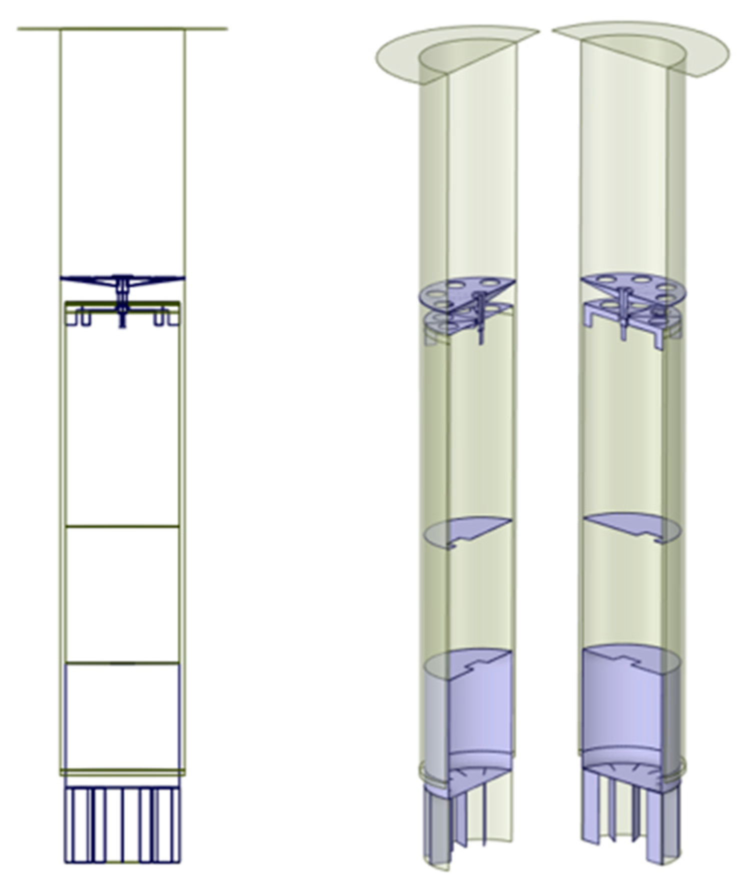
Figure 1 shows a cross-sectional view of the rotor sail structure in this study. The rotor sail under investigation is a large rotating structure with a cylindrical rotor with 30 m in total height and 3 m in diameter. The mid-plate, which connects the cylindrical rotor and the rotor shaft, is located 20 m above the bottom of the cylindrical rotor. The upper bearing set consists of one roller bearing and a thrust bearing, with the roller bearing positioned at 18.9 m and the thrust bearing at a height of 18.6 m. The lower bearing set is located 0.21 m above the bottom and supports the radial load. These detailed geometric dimensions refer to the ongoing development of the rotor sail in this study. The positions of support points and geometric sizes are relevant not only from a structural standpoint but also to aerodynamic performance. Therefore, future research should focus on optimizing the structure of the rotor sail, addressing both structural reliability and performance considerations. In this study, we concentrate on proposing two modeling techniques and an analysis method, using a reference model to interpret dynamic responses.
The cylindrical rotor and Thom disk are composed of a composite material with a thickness of 30 mm. The rotating structure of the rotor sail has a total mass of 18,000 kg. Generally, the inner tower of the rotor sail has a partition wall to facilitate maintenance. However, for the sake of analysis simplification, the partition wall was neglected, and the inner tower was modeled as a cylindrical inner tower with an identical mass and stiffness. Detailed information on the mass of the rotor sail is provided in
Table 1.
The cylindrical rotor operates at a maximum rotational speed of 180 RPM (revolutions per minute), indicating relatively low RPM in terms of rotor dynamics. However, due to the large diameter of the rotor at 3 m, the linear velocity of the rotor reaches 28.3 m/s, and if vibration occurs due to the high mass, significant vibrational energy can be transmitted to the structural components of the vessel. Additionally, both the Thom disk and the cylindrical rotor are made of composite materials, which may introduce mass imbalance due to manufacturing variations and eccentricity during the assembly process. In this study, a simplified 4DOF rotor model was implemented to quickly calculate the vibration response of the rotor sail, allowing for comparison with the vibration levels observed in the actual system. The model’s validity and the range of its effectiveness were analyzed by comparing the results with a finite element (FE) model and examining the modeling errors due to variations in the stiffness at the support points.
3. Rotor Sail 4DOF Model
The four-degree-of-freedom (4DOF) rotor model is the simplest analytical model used to analyze the dynamic behavior of a rotor. It assumes a rigid rotor supported by stiffness and damping, neglecting the bending deflection of the rotor. In terms of dynamic behavior analysis, the model considers horizontal and vertical translational motions (x, y) in the cross-sectional plane with the rotor’s mass center as the reference point, as well as rotational motions (α, β) about two axes with respect to the mass center, resulting in a total of 4 degrees of freedom.
In the 4DOF model, it is assumed that the rigid rotor has a concentrated mass at its mass center. The rotor’s dynamic characteristics are analyzed by defining support points at both ends. In the case of the rotor sail described earlier, there are a total of three support points: two bearings in the upper support and one bearing in the lower support. The upper support consists of one roller bearing with support stiffness () and one thrust bearing with support stiffness (). The lower support has a support stiffness () due to a single roller bearing.
Since the distance between the two upper bearings is very close compared to the overall length of the rotor, the 4DOF model in this study simplifies the two upper bearings into a single equivalent bearing (
) as follows:
Furthermore, stiffness of the upper support point can be considered as the structural stiffness of the inner tower (
) and the supporting bearing being connected in series. Therefore, in
Figure 2, it is assumed that there are two stiffnesses arranged in series at the top. The structural stiffness related to the bending of the inner tower was determined using the first lateral bending natural frequency (
) obtained through modal analysis using the finite element model of the inner tower. The relationship equation between the equivalent stiffness (
) and the natural frequency for a simple cantilever beam was used, and the symmetric structural stiffness values (
) are obtained by substituting the natural frequency [
38]. In the equation,
represents the total mass of the inner tower.
Figure 2 shows the schematic of the simplified 4DOF rotor model mentioned above.
The bearing stiffness in the radial direction is generally considered to be isotropic. Therefore, the upper bearing stiffness (
) and the lower bearing stiffness (
) can be defined symmetrically with respect to the x and y axes as follows:
The distance from the mass center to the upper bearing point is defined as , the distance from the mass center to the lower bearing point is defined as , and the distance from the mass center to the Thom disk of the rotor sail is defined as .
To derive the natural frequencies of the 4DOF model, we can establish the free vibration models corresponding to each degree of freedom [
39]. The equations of motion for the rotational motions along the
x and
y axes include coupling terms (
) due to the gyroscopic effect.
In this case,
represents the total mass of the rotor sail, including the cylindrical rotor, Thom disk, and mid-plate.
denotes the transverse (in the X and Y directions) moment of inertia of the rotating body, while
represents the axial moment of inertia.
are the damping values at each bearing support point (see
Table 2), and
signifies the rotational speed of the cylindrical rotor. The mass, moment of inertia, and geometry information used in the 4DOF model are summarized in
Table 2, which was obtained from the three-dimensional geometry model of the rotor sail shown in
Figure 3.
The previous set of equations of motion can be represented in matrix form as follows:
Assuming a harmonic response for the displacement and angular responses, we can express the free vibrational model of the rotor sail in a simple matrix multiplication form as follows:
where
represents the inertia matrix, which consists of the mass and rotational inertia components from the previous equation;
represents the damping matrix, including the gyroscopic term; and
represents the stiffness matrix composed of the support stiffness values.
In the free vibration model, the natural frequencies associated with the rotational characteristics can be obtained as the imaginary parts of the solutions to the characteristic equation, which can be expressed as follows:
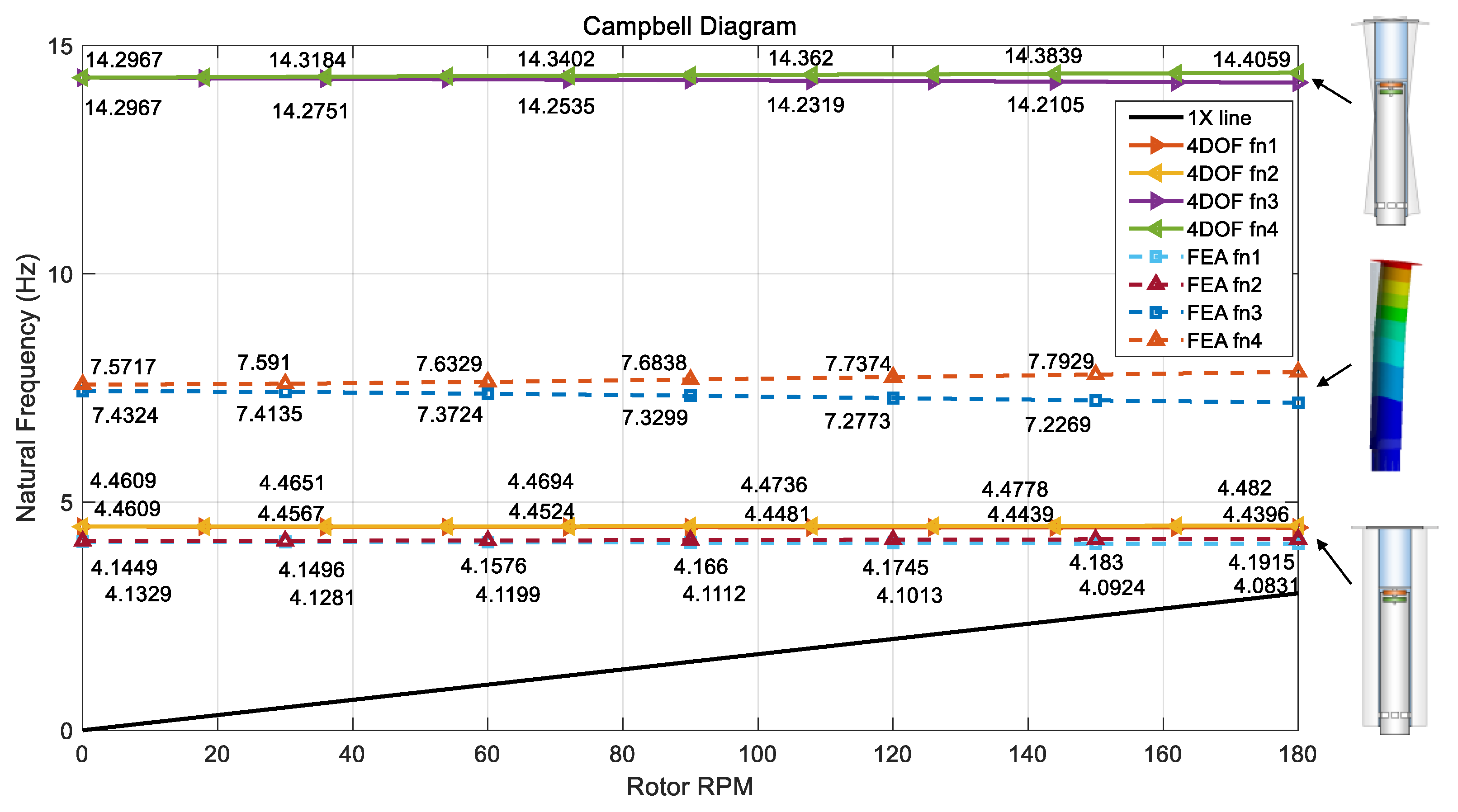
Therefore, by incorporating the matrix, which accounts for the gyroscopic term and its dependence on the rotational speed, we can obtain the natural frequencies of the rotor sail as a function of its rotational speed.
In order to calculate the response due to mass imbalance, which is primarily caused by the centrifugal forces acting on the rotating body, we can introduce a harmonic external force in the equations of motion. The potential locations where imbalance may occur in the rotor sail are the Thom disk and mid-plate, where mass is concentrated. As the mass of the cylindrical rotor is distributed along the length rather than in the radial direction, the imbalance is considered to be low.
We define the imbalance mass at the top Thom disk as
and the imbalance mass at the mid-plate as
. Assuming that the two imbalance masses are in phase, the harmonic external force can be expressed as follows:
When incorporating the imbalance force into the equation as an external excitation term, it can be represented in matrix form as follows:
To perform numerical integration for calculating the response, new state variables
can be defined as follows:
After obtaining
, the time response can be calculated by numerically integrating it over time steps. To calculate the amplitude of the frequency response, the following transfer function matrix with the force vector can be used:
In this study, the natural frequencies and frequency response results of the 4DOF model were compared with the FEM analysis results to evaluate the limitations and validity of the analysis.
4. Finite Element Model of the Rotor Sail
The finite element analysis of the rotor sail was performed using ANSYS R1 2021 Mechanical software. Modal analysis was conducted using the modal analysis module of ANSYS mechanical to obtain natural frequencies and critical speeds. Harmonic analysis was also performed to calculate the harmonic response due to imbalance mass.
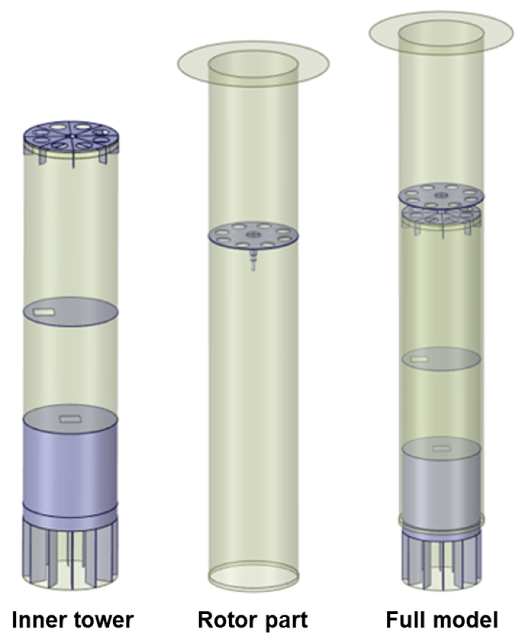
The finite element analysis model of the rotor sail can be divided into the rotor part and inner tower, as shown in
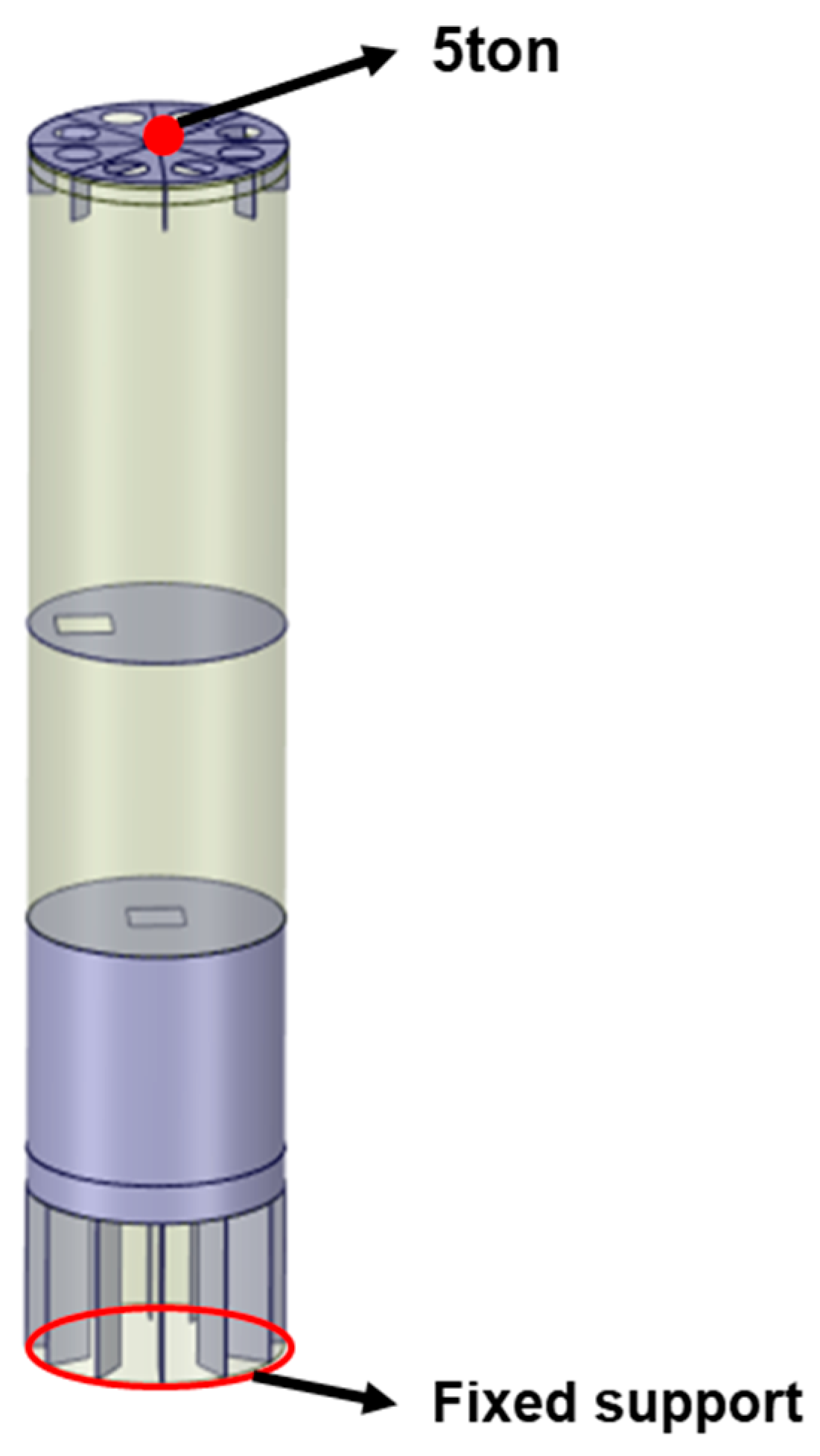
Figure 4. The boundary conditions of the inner tower are as depicted in
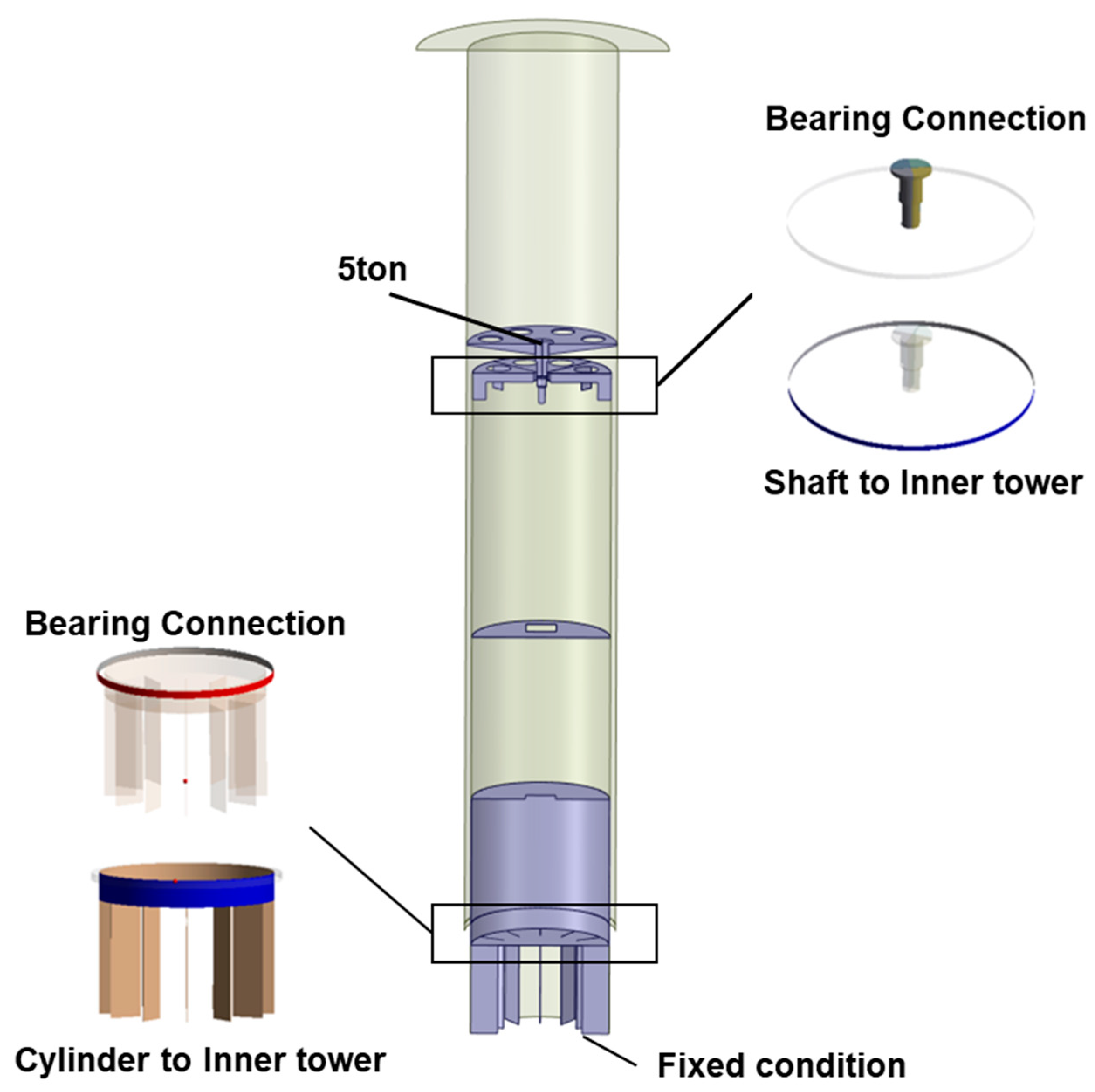
Figure 5, where the bottom surface is fixed to the foundation of the ground. The top surface is subjected to a point mass of 5000 kg, representing the weight of equipment (e.g., electric drive, gearbox, etc.) required for the operation of the rotor sail. The top of the inner tower and the drive shaft are supported by two bearings, while the bottom of the cylindrical rotor and the inner tower are connected through one bearing using a body-body connection condition. The bearing stiffness in the radial direction is considered to reflect the support stiffness.
In the modal analysis, the thin structure of the Thom disk can generate multiple local modes. However, these structural local modes of the disk are not relevant to the rotor modes of interest in this study. Therefore, the Thom disk was set as a rigid structure to prevent the occurrence of local modes. The cylindrical rotor, mid-plate, and drive shaft were fully bonded to each other. The boundary conditions for the finite element analysis can be seen in
Figure 6.
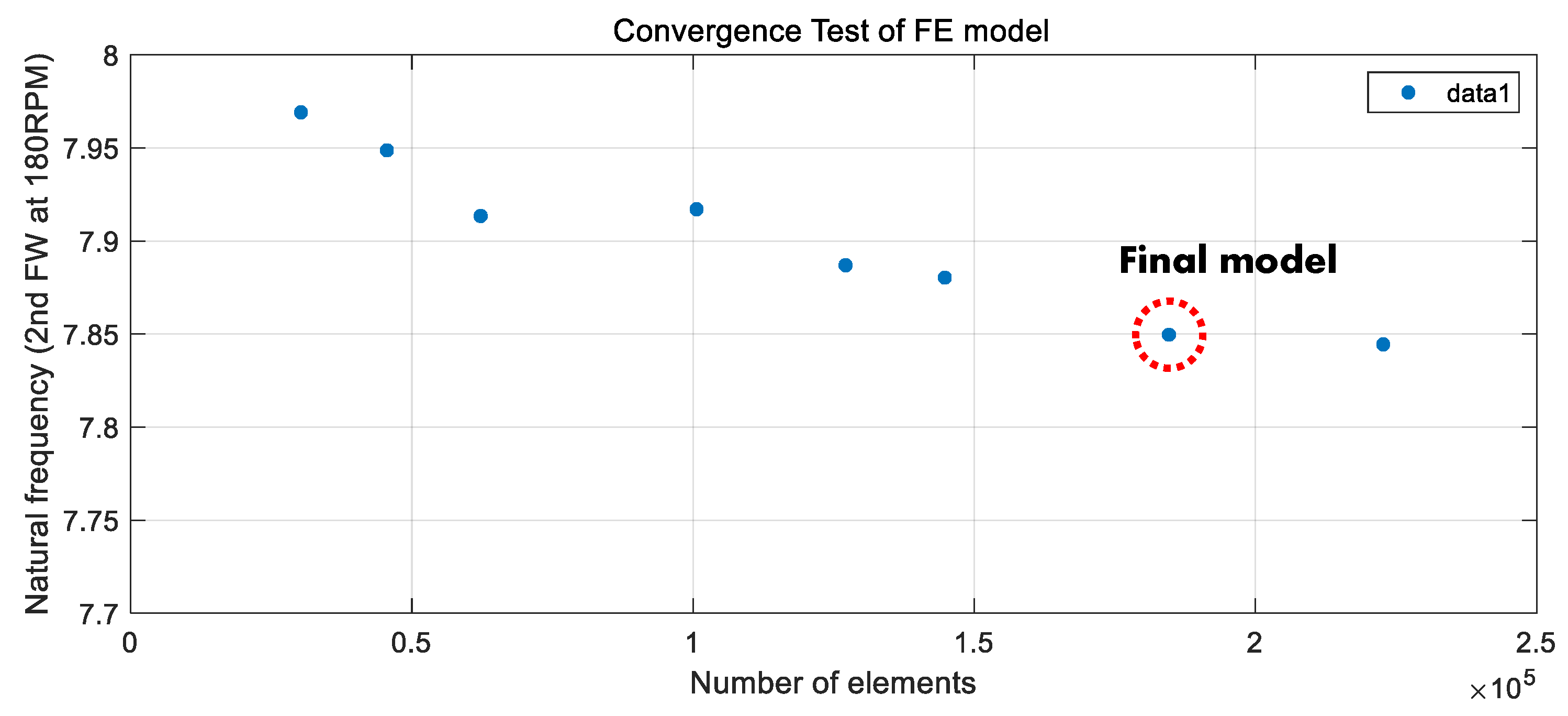
In the modal analysis, the natural frequencies were computed for a total of seven rotational speeds (0 RPM, 30 RPM, 60 RPM, 90 RPM, 120 RPM, 150 RPM, 180 RPM). For the harmonic response analysis considering imbalance, rotating forces were applied as imbalance conditions at the positions of the Thom disk and the mid-plate. With various magnitudes and phases of the imbalance, force analyses were repeatedly conducted. To validate the reliability of the finite element model, a convergence test was conducted by varying the number of elements. As shown in
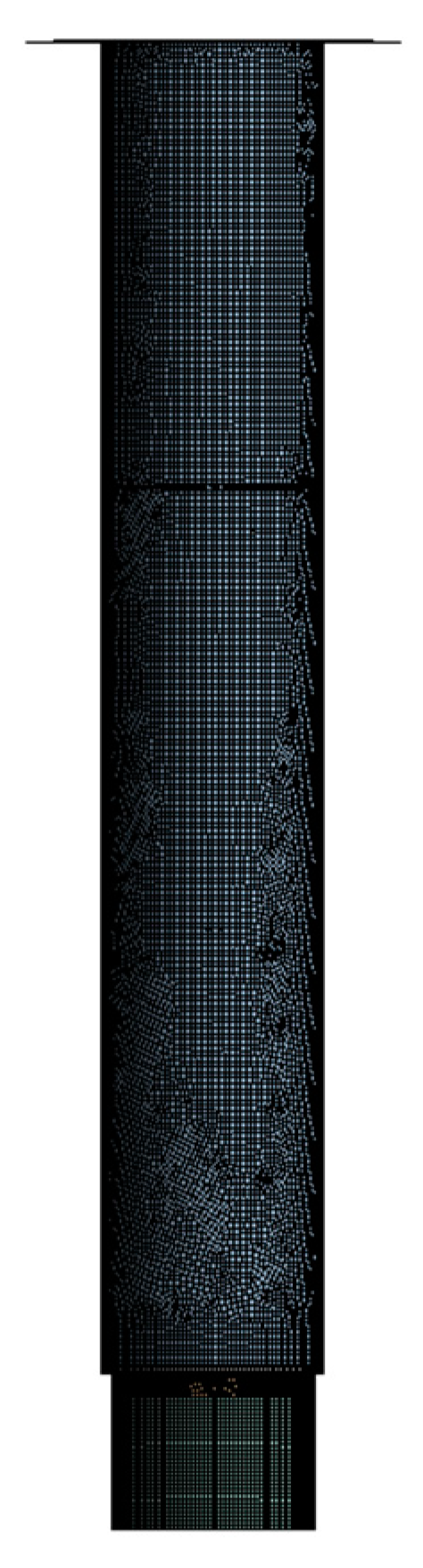
Figure 7, it was confirmed that the value of the second natural frequency converged to a certain value with an increase in the number of elements. To enhance the efficiency of the analysis, the number of elements at which the value saturated was applied to the model. The inner tower was modeled with 260,000 nodes and 130,000 elements. The rotor model was implemented with 70,000 nodes and 50,000 elements. The overall model of the rotor sail, including the inner tower and other components, consisted of 330,000 nodes and 180,000 elements, as shown in
Figure 8.
6. Harmonic Response
Typically, the mass imbalance of rotating bodies is controlled through balancing operations based on the permissible residual unbalance amount defined in ISO [
39]. However, rotor sails, being large rotating structures composed of composite materials and heights of up to 30 m, pose limitations on controlling residual unbalance using conventional balancing equipment. Therefore, the mass imbalance of the rotor sail is likely to induce vibration in the rotating body. In this study, the permissible residual unbalance amount for the rotor sail was calculated based on the G6.3 standard used in applications such as pumps and electric motors. This calculation was then applied to the rotor sail to evaluate its harmonic response at various excitation frequencies. The permissible residual unbalance amount varies depending on the rotor’s mass and rotational speed. For a maximum rotational speed of 180 RPM and a total rotor weight of 18,009 kg, it can be calculated as 6.018 kgm.
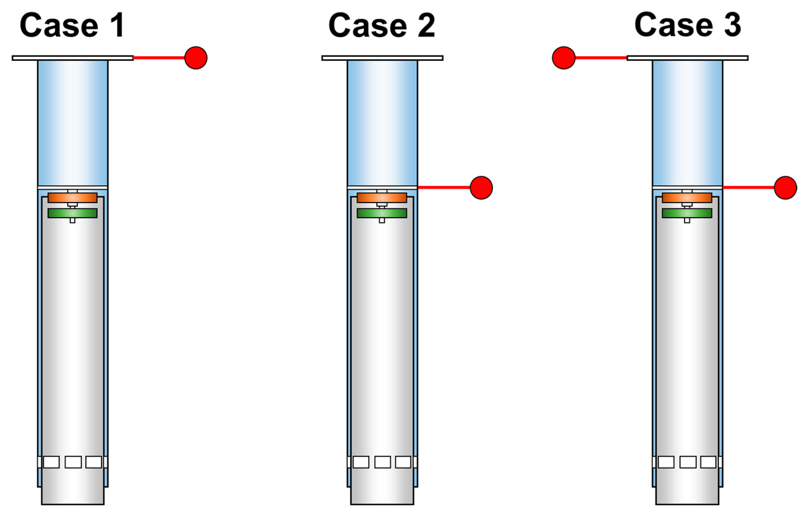
There are two main locations where mass imbalance can occur in the rotor sail: Firstly, at the topmost Thom disk, which has a wide plate-like structure relative to the cylindrical rotor. If the rotation axis and Thom disk are offset during installation, it can result in mass imbalance. Secondly, at the mid-plate, which is composed of ship structural steel and has a higher mass concentration compared to the cylindrical rotor. In this study, harmonic response analyses were conducted for three cases where imbalance mass could exist in the Thom disk and mid-plate.
Figure 13 illustrates these three mass imbalance conditions. Case 1 represents imbalance mass in the Thom disk, while case 2 represents imbalance mass in the mid-plate. Since it is not feasible to perform a balancing check for the entire rotor sail, which is a large rotating structure, static balancing was only conducted, but the possibility of dynamic imbalance still exists. Therefore, case 3 considers the scenario where the Thom disk and mid-plate have simultaneous imbalances of the opposite phase, representing a dynamic imbalance condition. The analysis was performed using both the 4DOF model and finite element analysis for all three conditions, and the results were compared and analyzed.
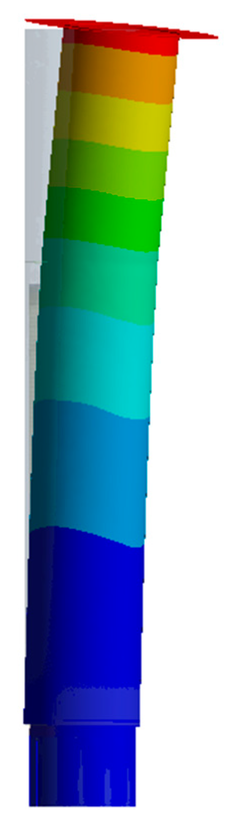
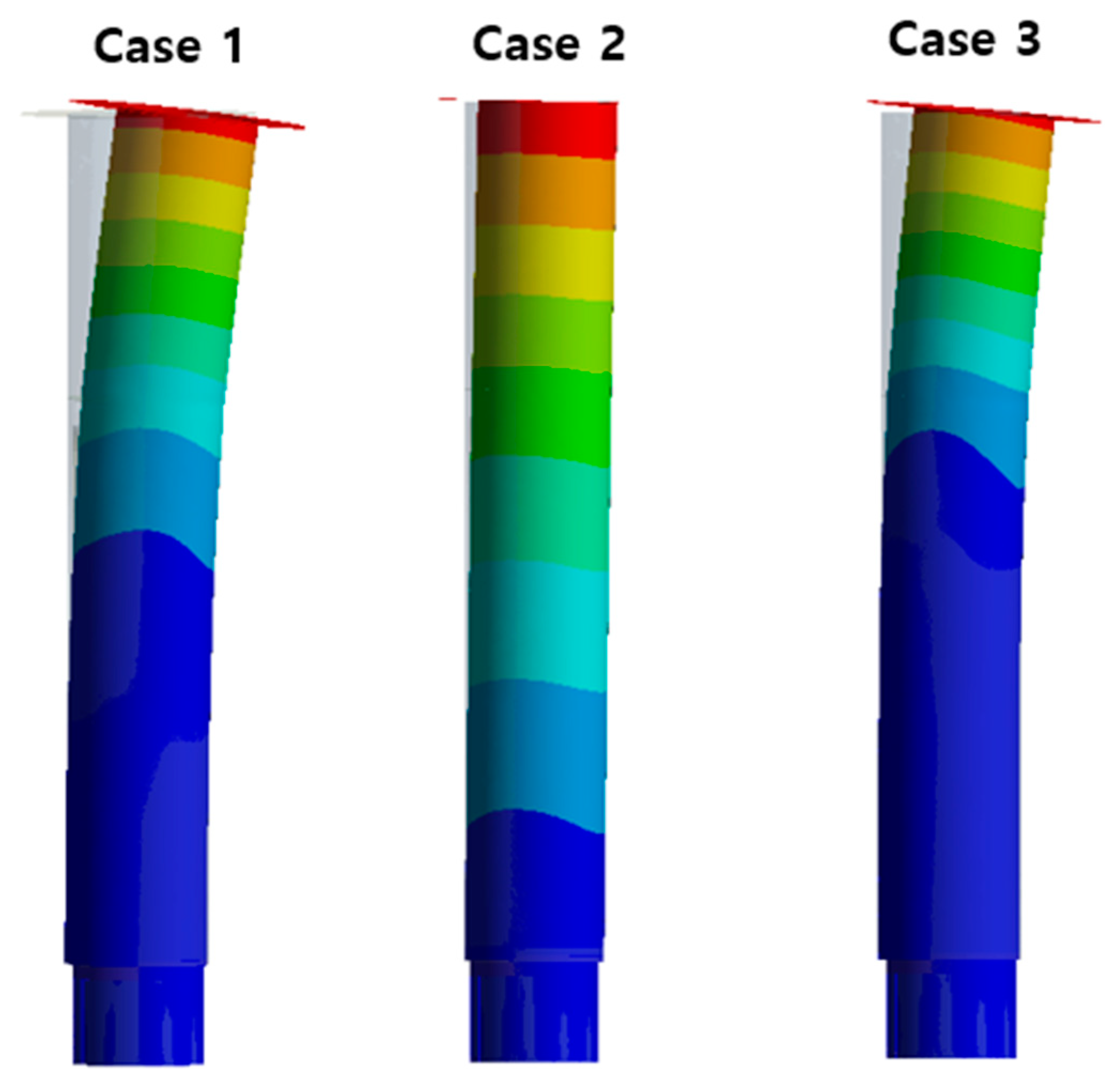
Figure 14 presents the mode shapes for each case as obtained from the finite element analysis.
Figure 15 shows the frequency response (harmonic response) for the three imbalance cases, specifically the vibration velocity results at the topmost section of the inner tower, which corresponds to the support region of the upper bearing. The results shown as solid blue lines and circular markers represent the calculations from the 4DOF model, while the red triangular markers represent the results from the FEM analysis. Considering that the maximum rotation speed of the rotor sail is 180 RPM (3 Hz), the analysis focused on the harmonic response up to 3 Hz, as it represents the maximum excitation frequency due to mass imbalance.
From the results shown in
Figure 15, it can be observed that the analysis results from the 4DOF model and FEM exhibit relatively similar trends for each imbalance case. Since the first natural frequency occurs around 4 Hz, the overall trend in the analysis results up to 3 Hz shows a monotonic increase. However, it can be noted that Case 1 exhibits larger deviations compared to Cases 2 and 3. This is due to the mass imbalance imposed solely on the Thom disk, as shown in case 1 of
Figure 14, which leads to bending of the rotating part of the rotor sail. The FEM results consider this bending effect, resulting in higher lateral displacements and velocities compared to the assumption of a rigid body rotation in the 4DOF model. In Case 2, where mass imbalance occurs in the mid-plate, which is closer to the center of gravity, the bending effect decreases, resulting in similar harmonic response within the desired range of 3 Hz.
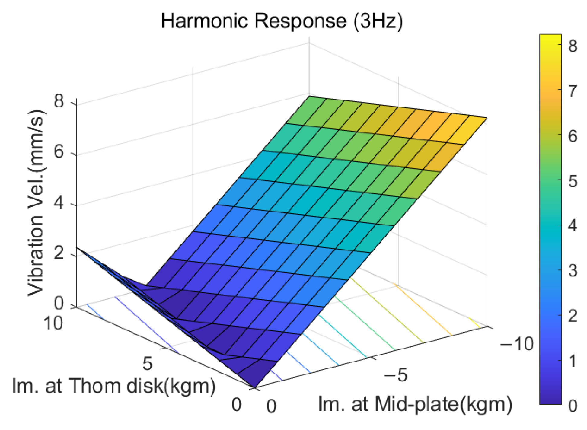
The vibration velocity results for the combined mass imbalance conditions occurring in the Thom disk and mid-plate are shown in
Figure 16. The mass imbalances in the Thom disk and mid-plate are depicted in an out-of-phase condition, and the vibration velocity is plotted. The maximum vibration velocity occurs when the mass imbalance is concentrated in the mid-plate.
Figure 17 presents the vibration velocity at the upper bearing support for the case where the mass imbalances in the Thom disk and mid-plate have the same phase (in-phase condition) in the combined mass imbalance condition. The maximum vibration velocity occurs when the mass imbalances in the Thom disk and mid-plate are in the same phase, reaching approximately 10.6 mm/s. This maximum vibration velocity value can be evaluated by comparing it with the allowable vibration level at the support of the rotor sail.
The vibration model of the rotor sail is linear, so the response under the condition of combined mass imbalance is essentially the linear combination of the responses under each individual mass imbalance condition. Therefore, we can expect the vibration velocity at the upper support to be predicted using the following simplified linear equation:
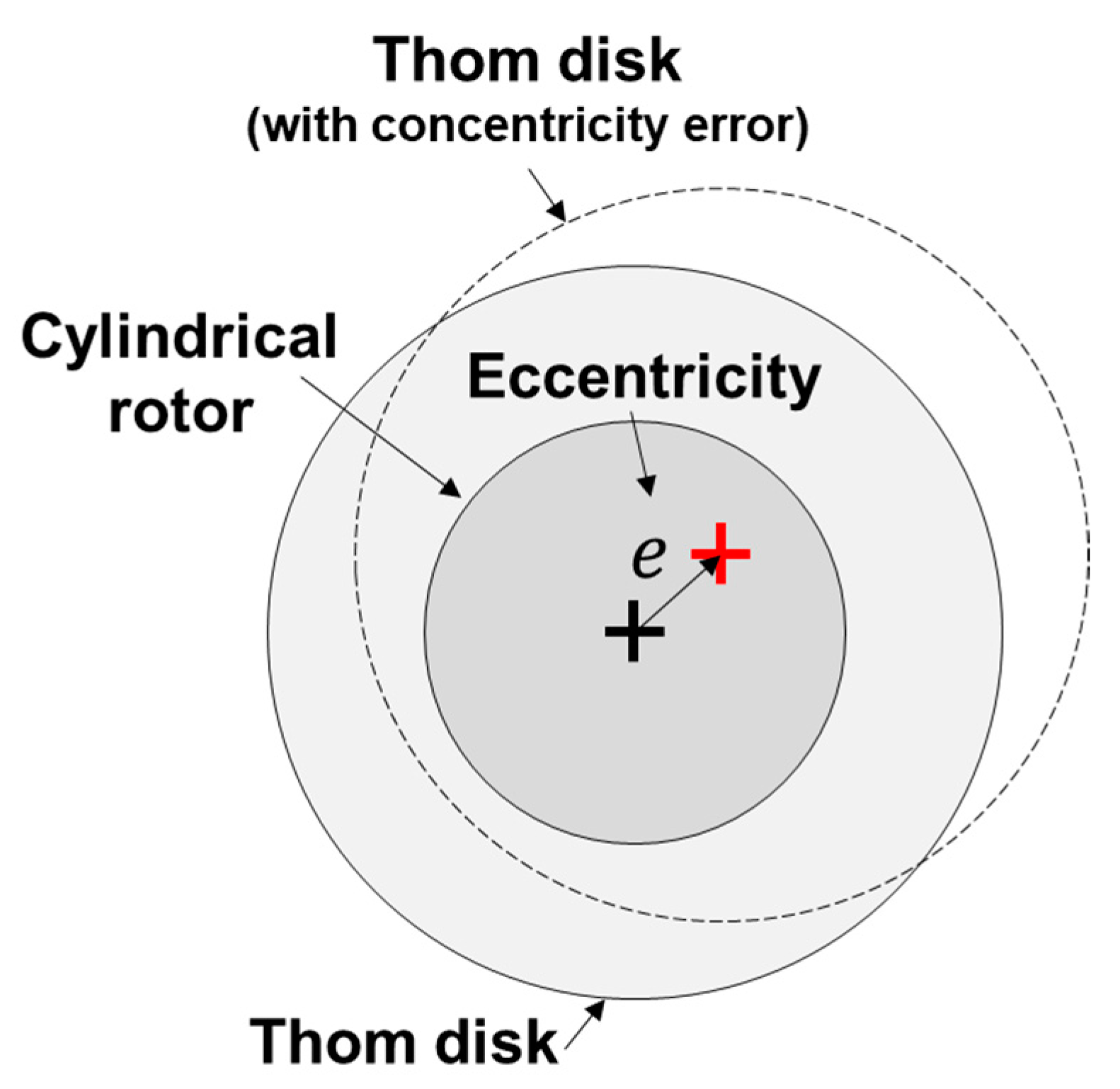
In a rotor sail, significant vibrations can occur due to the mass imbalance of the mid-plate. However, for rotational structures made of structural steel, the management of mass imbalance can be achieved using a balancing machine. On the other hand, in the case of the Thom disk, which is made of composite material and assembled with the cylindrical rotor, there can be eccentricity (offset) errors between the rotational axis and the Thom disk (
Figure 18). If we limit the vibration velocity to 6.3 mm/s, we can deduce from the previous linear equation that a mass imbalance of up to 26.58 kg is permissible for the Thom disk. Considering the eccentricity error as the eccentricity from the rotational axis to the total mass of the Thom disk, with a weight of 1096.9 kg, we can provide the guideline for the maximum allowable eccentricity error to 24 mm. Thus, the rotor vibration model derived in this study allows for a quick estimation of the response to rotor vibrations, making it useful for providing design criteria and guidelines during the design phase. Furthermore, by implementing this model in a real-time simulation environment, it can be applied to evaluate the structural integrity of the rotor sail by monitoring the signal deviation between the measured signals in an actual rotor sail and the rotor sail model.
7. Conclusions
In this study, two methods for analyzing the dynamic response of a rotor sail were discussed. Firstly, the 4DOF simplified rotor sail model was derived to obtain low-order natural frequencies and to assess dynamic responses quickly. And then, finite element analysis was introduced for the rotor sail to validate the effectiveness of the 4DOF simplified rotor sail model. By comparing two modeling approaches, we could summarize analysis results as follows:
- -
The 4DOF model can estimate low-order four natural frequencies including two forward whirl natural frequencies;
- -
The 4DOF model can quickly estimate the first natural frequency for cylindrical mode with about 0.3 Hz difference with FEA results;
- -
The 4DOF rotor sail model is valid for dynamic response analysis in designs where no critical speed occurs, i.e., below the first natural frequency;
- -
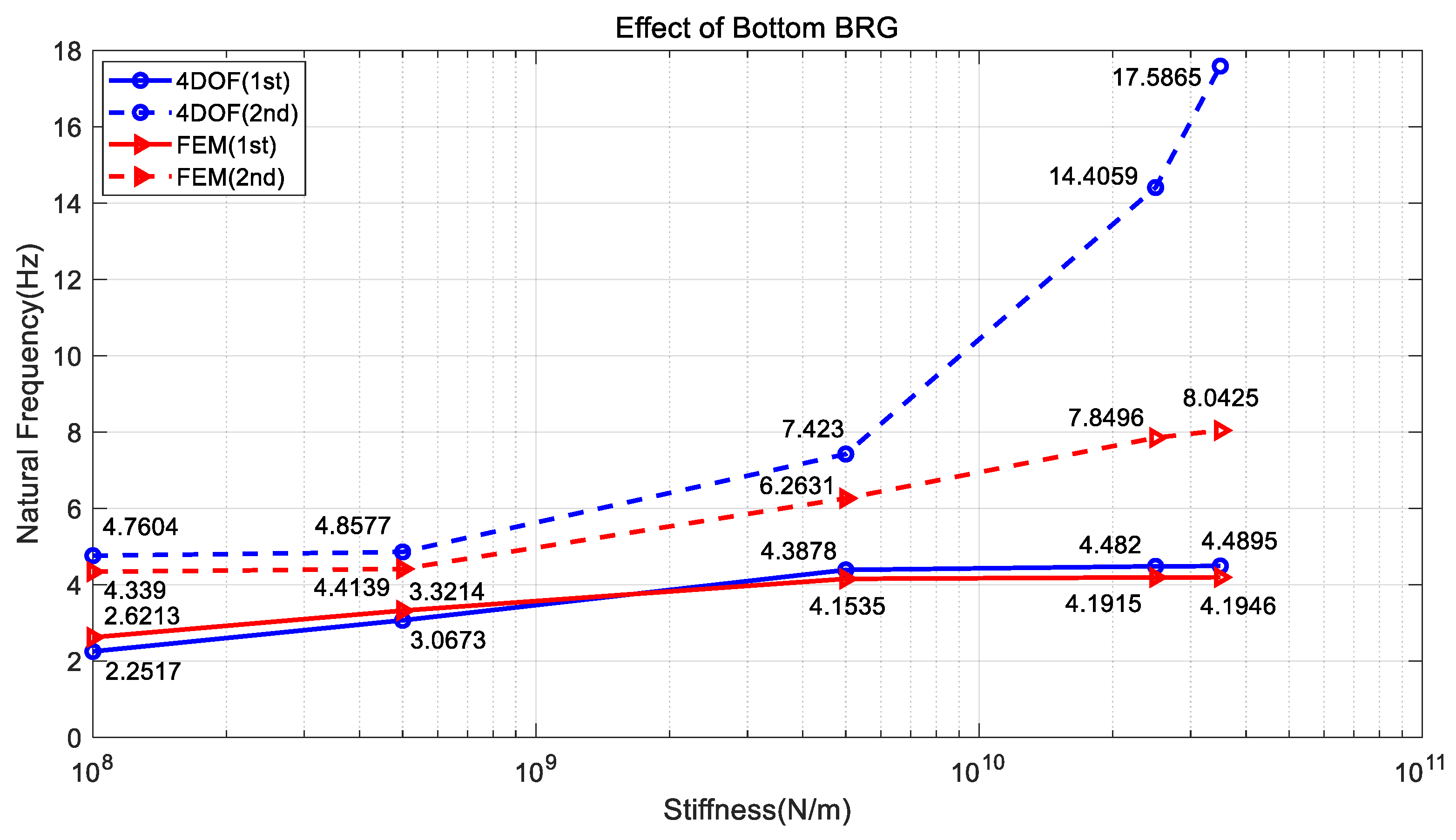
A bottom supporting bearing significantly effects on the dynamic responses of the rotor sail rather than upper supporting bearings;
- -
The maximum vibration velocity occurs in case of mid-plate imbalance condition;
- -
The maximum allowable installation error for Thom disk of the rotor sail can be suggested to be 24 mm, considering the dynamic response.
Based on the results in the study, a guideline for constraints on the eccentricity due to assembly errors can be established during the initial design stage. However, the limitations of this study can be revealed as follows:
- -
The 4DOF model cannot estimate rotor bending mode if it is below the maximum speed range;
- -
The geometrical dimensions of this study are needed to be optimized to improve the dynamic responses;
- -
In the further works, two modeling approaches need to be verified in detail using the real experimental data;
- -
The dynamics can be improved with including the detailed bearing dynamics.
While this study focused on the analysis methods and reviews of the support structure for the developmental stage of the rotor sail, as well as the review of imbalance, future research will address additional investigations to overcome the aforementioned limitations.
A rotor sail is an alternative solution to easily reduce fuel consumption and greenhouse gas emissions by adding it to existing ships. However, in terms of practical application, there is still a need for research on the stable operation of rotational structures, as well as the evaluation of bearing support structures for wear and lifespan. In future research, we will further develop this analysis model and establish an analysis environment that can predict the detailed dynamic behavior of bearing supports and assess their wear performance and operating lifespan. The finite element analysis and 4DOF model in this study exhibit mutually similar rotor dynamics characteristics, suggesting a form of mutual validation. However, for a reliable validation of both models, experimental data need to be obtained in the future. Therefore, in subsequent research, it is essential to measure the dynamics of a full-scale rotor sail experimentally or a scaled-down rotor sail and validate the results against the findings of this study. Despite these limitations in the current study, it holds significance in presenting the 4DOF model and finite element analysis results, which can be utilized in the early stages of development for designing the basic structure and predicting the dynamic behavior of the rotating system of a rotor sail.


