Article

Multibody Analysis of Wave Energy Converters and a Floating Platform in the Time Domain

1
Multidisciplinary Graduate School Program for Wind Energy, Jeju National University, Jeju-si 63243, Republic of Korea
2
Department of Mechanical & System Design Engineering, Hongik University, Seoul 04066, Republic of Korea
*
Author to whom correspondence should be addressed.
J. Mar. Sci. Eng. 2024, 12(2), 265; https://doi.org/10.3390/jmse12020265
Submission received: 28 December 2023 / Revised: 24 January 2024 / Accepted: 29 January 2024 / Published: 1 February 2024

Abstract

:
Generally, new and renewable energy systems generate electricity by installing and operating multiple modules simultaneously. In the Republic of Korea, recent studies and developments have focused on asymmetric wave energy converters (hereafter referred to as rotors) suitable for marine environments off the western coast of Jeju. These rotors are arranged on a large floating truss-structure platform and designed to harness electricity from the rotors’ pitch motion. However, when multiple rotors operate on a platform, their behavior diverges from that of a single module due to hydrodynamic interactions between them. Moreover, because the rotors are connected to the floating platform, their motion is influenced by the platform’s dynamics. In this study, a time-domain multibody motion equation was established to analyze changes in the behavioral characteristics of the rotors, both with and without a floating platform. The hydrostatic and hydrodynamic coefficients were derived in the frequency domain using WAMIT, a commercial code based on linear potential flow theory for three-dimensional diffraction/radiation analyses. The motion equation was then applied under regular and irregular wave conditions using OrcaFlex version 11.3, a marine systems design and analysis program. The resulting behaviors were compared to elucidate the influence of the platform and hydrodynamic interactions on the rotors’ performance.

1. Introduction

Active research on power generation systems utilizing new and renewable energy sources is underway, driven by the global initiative to achieve decarbonization. Recently, many research studies have expanded from terrestrial to marine environments to overcome spatial and societal constraints [1]. The ocean harbors a variety of renewable energy sources, including tides, ocean currents, waves, wind power and solar heat, as well as the energy potential from differences in seawater temperature and salinity. Consequently, this facilitates a wide range of research opportunities in various fields. Typically, renewable energy systems enhance power production within confined spaces by installing and operating multiple modules simultaneously. This process also applies to wave energy converters (WECs) that produce electrical energy from wave energy. However, when multiple WECs are operated simultaneously, their motion response differs from that of a single entity due to hydrodynamic interactions between each unit.
In 2016, the research project “Development of Fundamental Technologies for a 1 MW Class Arrayed-Buoy Wave Energy Converter in Various Sea Conditions” was undertaken in South Korea, where Salter’s duck rotor, as proposed by Stephen Salter [2,3,4,5], was utilized. Subsequently, this model (hereafter referred to as a rotor) was redesigned and developed to suit the ocean environment in the western part of Jeju, South Korea (see Figure 1) [6,7,8,9]. In previous studies, a one-degree-of-freedom system was constructed. An analysis of this simplified system, featuring a rotor connected to a fixed rotational axis submerged at a specific depth, was then performed.
However, in a real sea, multiple rotors are designed to extract power by connecting them to a large floating truss platform. In this design, understanding the hydrodynamic interaction between the floating platform and the multiple rotors becomes crucial. Furthermore, given that the rotors are connected to the floating platform, the dynamics of the floating platform can affect the rotors’ motion response. In particular, the motion response of the rotors connected to the floating platform differs marginally from that of a single rotor connected to a fixed axis of rotation.
Numerous studies have focused on multibody interactions, primarily exploring the hydrodynamic interactions between WECs and floating structures [10,11,12,13,14,15,16]. Konispoliatis et al. [17] studied the effect that a fixed vertical breakwater has on the hydrodynamic characteristics of multiple WECs parametrically. A notable study delved into the dynamic behaviors of a torus-type WEC which exhibits a heaving motion in conjunction with a spar-type floating body [18]. Zhou et al. [19] studied the dynamic behaviors of multiple heaving WECs and semisubmersible platforms, revealing that a prominent new power peak emerges when the platform and WECs are in a synchronized state. Furthermore, various parametric studies were conducted to optimize the system by introducing frequency-domain-coupled hydrodynamics, considering the constraints and power output through the relative motion between the integrated WECs and the semi-submersible platform [20]. Kamarlouei et al. [21] explored a hybrid system comprising 12 WaveStars surrounding a semisubmersible platform, revealing that the platform’s heaving and pitching motions could be effectively mitigated by WECs with appropriately tuned damping in the power take-off (PTO) system. Ghafari et al. [22] examined the effect of the number of WECs on a hybrid system’s performance. They indicated that a large number of WECs contributed to system stabilization in terms of pitch. Moreover, the power output improved when the WECs’ movements aligned in phase with those of the platform. Cheng et al. [23] validated the feasibility of different types of WECs integrated into floating platforms and showed their synergy. Yazdi et al. [24] conducted a parametric study on the dynamic responses of multiple Salter’s duck WECs and a braceless floating semisubmersible, focusing on varying numbers of WECs, wave periods and wave heights.
In this study, a time-domain coupled equation of motion for a multibody analysis was formulated to ascertain differences in motion response. In contrast to the majority of previous studies that considered only a single degree of freedom for the rotor, this study incorporated the surge and heave effects interacting with the floating body. A numerical model was developed to include the hydrodynamic interaction effects between the rotors and the platform, adhering to necessary constraints such as connectivity. Then, the motion response was calculated through a regular wave simulation. An irregular wave simulation was also performed to calculate the motion responses and extract power at the installation site. Finally, the results were compared with those obtained from a rotor connected to a fixed rotational axis. This approach facilitated an assessment of the in-wave power generation performance of the actual wave energy structure.

2. Numerical Analysis

2.1. System Identification

In this study, a numerical analysis was conducted on the Salter’s duck model depicted in Figure 2. The rotor was designed with a distinct shape that varied between the front (facing the direction of the incident wave) and the rear sides to enhance energy absorption efficiency [25]. Previous studies conducted parametric analyses focusing on the initial beak angle and ballast weight based on these geometric characteristics. Subsequently, the rotor was redesigned to optimize its performance in the ocean environment west of Jeju Island, South Korea, with a water depth of 80 m. As illustrated in Figure 2a, the rotor achieves static equilibrium by itself when floating in calm water (without waves). In this state, the rotor’s rotational center is positioned 1.6 m below the water surface, with a draft of 3.6 m and a beak angle of 60°.
The floating platform, a semi-submersible truss structure shown in Figure 2b, also maintains a static equilibrium state with a draft of 5.35 m in calm waters. Figure 2c shows a central platform oriented toward the direction of the incident wave which can connect four rotors. The entire platform hosts a total of 20 rotors, of which 16 rotors are split into two groups and connected to the two wing platforms on the left and right sides. The angle (α) between the central and wing platforms is adjustable based on environmental conditions and is set at 150° during operation. The spacing between each rotor is 3.5 m, and the floating platform is connected by two hawsers to a weathervaning buoy moored by multiple lines, allowing for orientation adjustments according to changes in the incident wave direction (see Figure 3).
In this study, to increase computational efficiency by reducing the degrees of freedom of the entire system, as shown in Figure 2c, the rotor connected to the wing platform was modeled as a single rigid body along with the floating platform, and its individual movements were not considered. Consequently, only the four rotors on the central platform were allowed to move. In conducting a multibody analysis of one floating platform and four rotors, the mass characteristics of the remaining 16 rotors were incorporated into the floating platform. Hereinafter, the term “platform” refers to the platform structure, including 16 rotors on the wing platform. The specifications of the single rotor and the entire platform, excluding the four central platform rotors, are detailed in Table 1 and Table 2, respectively.

2.2. Multibody Equation of Motion

In the initial design stages of a floating platform, the system is typically assumed to be linear, and its response in the frequency domain is calculated. This approach is advantageous due to its relative simplicity and the ability to yield results quickly. However, to more accurately simulate behavior in the actual ocean environment, it becomes essential to use a time-domain analysis which can account for nonlinear effects. Specifically, the rotor in this study exhibits nonlinear restoring characteristics, with the restoring moment varying rapidly based on the rotational angle, necessitating an analysis in the time domain.
For this study, the equation of motion was established using Newton’s second law, applying the Cummins equation [26], as shown in Equation (1). Notably, a multibody coupled equation of motion was formulated to express the behavior of multiple rotors connected to a floating platform.
M ξ ¨ + L r d ξ ˙ + B v i s + B p t o ξ ˙ + K r e s + K m ξ + C l i n k ξ = L w
The equation considers the hydrodynamic interactions between each floating body when analyzing the motion of two or more adjacent floating bodies. Consequently, all terms in the equation are presented in the form of a matrix or column vector, incorporating (6 × N) degrees of freedom corresponding to the number of floating bodies (N). In the next notation, “ p t f m ” and “ r t n ” used in the superscript of each variable denote the respective floating body as the platform and the nth rotor. Furthermore, i , j = 1 , 2 , , 6 and α , β = 6 n + 1 , 6 n + 2 , , 6 n + 1 , used in the subscript, indicate the degrees of freedom of the platform and the nth rotor, respectively.
M is the sum of two matrices, M i n e r and A . M i n e r includes the mass and mass moment of inertia, and A includes the added mass and the added mass moment of inertia at infinite frequency as components. B v i s and B p t o denote matrices for the linear viscous damping coefficient and the PTO damping coefficient, respectively. K r e s represents the coefficient matrix for the restoring load of the floating body (the platform and rotor), while K m is the coefficient matrix for the restoring load induced by the mooring line connected to the platform. L w is the wave excitation load and ξ ¨ , ξ ˙ and ξ represent the acceleration, velocity and displacement (or angular acceleration, angular velocity and angular displacement) of the platform and rotor, respectively. ξ ¨ , ξ ˙ , ξ and L w take the form of column vectors.
In order to depict the interdependence among the degrees of freedom of the floating body, the matrix components of M were assembled as illustrated in Equation (2). L r d ξ ˙ represents the radiation damping load and can be calculated using a retardation function matrix B , as depicted in Equation (3). The matrix B is expressible as shown in Equation (4).
M ξ ¨ = M i j p t f m M i α p t f m , r t n M α i p t f m , r t n M α β r t n ξ ¨ i p t f m ξ ¨ α r t n
L r d ξ ˙ = 0 B τ ξ ˙ i p t f m t τ ξ ˙ α r t n t τ d τ
B i α τ = 2 π 0 b r a d , i α ω c o s ω τ d ω
In Equation (1), the coefficients of the restoring load, hydrodynamic load ( A , b r a d ) and wave excitation load for the floating body were derived using Wave Analysis MIT (WAMIT version 7.1 [27]), a three-dimensional diffraction/radiation solver based on the linear potential theory. The above coefficients are a function of the incident wave frequency, and in this study, the coefficients were obtained for a total of 81 frequencies at intervals of 0.02 rad/s for incident wave frequencies ranging from 0.02 rad/s to 1.70 rad/s. For WAMIT calculations, geometrical details of the submerged portion of the floating body are necessary; these were numerically modeled using Multisurf version 9.0 [28] (Figure 4). For simplification in the hydrodynamic analysis of the floating platform, the truss structure atop the pontoon was omitted.
The coupled equation of motion assumes that both the viscous damping load and the PTO damping load are linear, expressed as loads proportional to the velocity of the floating body. Therefore, they are combined as in Equation (5).
B v i s + B p t o ξ ˙ = B v i s , i j p t f m + B p t o , i j p t f m B p t o , i α p t f m , r t n B p t o , α i p t f m , r t n B v i s , α β r t n + B p t o , α β r t n ξ ˙ i p t f m ξ ˙ α r t n
The component of B v i s can be calculated using the damping ratio ( κ ) obtained from free decay tests, with the assumption that total damping is the sum of linear viscous damping and radiation damping during the free decay test [29], as detailed in Equation (6). Free decay tests for the rotor were conducted using a 1/11 scale standalone model in a two-dimensional wave tank at Jeju National University, while platform free decay tests utilized a 1/30 scale model in a three-dimensional ocean engineering basin at KRISO (Korea Research Institute of Ships and Ocean Engineering). The damping ratios obtained from these experiments are presented in Table 3.
B v i s , i i = 2 κ i · M i n e r , i i + A i i ω 0 , i · ω 0 , i b r a d , i i ω 0 , i
In Equation (6), M i n e r , i i represents the mass or mass moment of inertia for translational or rotational motion, respectively, and ω 0 , i denotes the undamped natural frequency of the degree of freedom i . A i i ω 0 , i and b r a d , i i ω 0 , i correspond to the added mass and radiation damping coefficients at the undamped natural frequency. The undamped natural period values ( T 0 , i = 2 π / ω 0 , i ) are specified in Table 1 and Table 2. In general, when calculating the linear damping coefficient of a floating body, the assumption is made that the influence of each degree of freedom is more significant than the coupling effect between degrees of freedom. Consequently, only the diagonal component B v i s , i i is calculated, while the off-diagonal component B v i s , i j is set to zero. In the actual free decay experiment, the setup allowed for the occurrence of only one degree of freedom at a time, whether it was surge, heave or pitch.
In this study, the rotor generates power through pitch motion. Given that the rotor and platform share the same axis of rotation, the PTO mechanism must be expressed in terms of the relative rotational velocity between the rotor and the platform. The PTO damping coefficient thus appears in individual pitch terms for both the rotor and platform, as well as in their pitch coupling terms. The PTO damping coefficient utilizes the optimal value derived from previous research.
Floating bodies typically exhibit stability against heave, roll and pitch. Nevertheless, when it comes to horizontal motions like surge, sway and yaw, stability needs to be ensured by employing supplementary devices, such as a mooring system. To achieve this, a term representing the restoring load was formulated, as illustrated in Equation (7).
K r e s + K m ξ = K r e s , i j p t f m + K m , i j p t f m 0 0 K r e s , α β r t n ξ i p t f m ξ α r t n
A linear hydrostatic coefficient was applied to the K r e s of the floating platform. However, applying a linear coefficient to K r e s corresponding to the rotor’s pitch motion poses challenges for obtaining an accurate response due to rapid changes in the volume and center of buoyancy of the rotor’s submerged portion depending on its rotational angle. The restoring moment of the rotor exhibits significant nonlinearity with changing rotational displacement, as illustrated in Figure 5. Therefore, the restoring moment coefficient of the rotor is set to change nonlinearly in accordance with its angular displacement. In the time-domain simulation, the rotor’s rotational displacement is evaluated at each time step, and the corresponding restoring moment coefficient, as determined from Figure 5, is applied to the equation of motion.
The influence of the mooring line is typically addressed through a floating-body–mooring coupled analysis method using a finite element model wherein the inertia and drag forces acting on the mooring line must be considered. However, given that this study specifically focused on the coupled motion between the floating platform and the rotors, the mooring system was simplified to an equivalent spring system independently connected for each degree of freedom of the platform to represent its fundamental roles, maintaining the targeted natural period and ensuring platform stability. The equivalent spring stiffness coefficient ( K m ) of the platform was determined from Equation (8), thereby enabling the platform to achieve the undamped natural period specified in Table 2.
K m , i i = M i i + A i i ω 0 , i · ω 0 , i 2 K r e s , i i
Equation (8) derives from the undamped natural frequency ω 0 , i = K i i / M i i + A i i ω 0 , i , with K r e s subtracted from the total restoring coefficient K i i to prevent double-counting the hydrostatic restoring stiffness of the platform in the mooring stiffness K m .
Furthermore, the rotors are linked to their corresponding rotational axes on the floating platform. As a result of this assembly, the pitch motion of the rotor was allowed freedom, while the other degrees of freedom are bound to the floating platform, moving in unison. In order to facilitate the numerical implementation of this structure, constraint conditions for the floating body were formulated, as detailed in Equation (9).
C l i n k ξ = C l i n k , i j p t f m C l i n k , i α p t f m , r t n C l i n k , α i p t f m , r t n C l i n k , α β r t n ξ i p t f m ξ α r t n
Utilizing the constraint coefficient C l i n k indicates that identical degrees of freedom between the floating platform and rotor are connected by a robust linear spring. As pitch movement needs to be allowed, the term associated with pitch was assigned a value of zero.
The wave excitation load, denoted as L w , is represented as a column vector of values corresponding to each degree of freedom, as shown in Equation (10). However, the values take into account the diffraction effect between them when multiple floating bodies exist simultaneously.
L w = L w , i p t f m L w , α r t n
Based on the described equation of motion, a numerical analysis simulation was performed using OrcaFlex version 11.3 [30], a three-dimensional floating multibody dynamics tool that performs simulations in the time domain.

3. Results and Discussion

3.1. Regular Wave Simulations

In regular wave environments, floating bodies typically exhibit periodic motion dependent on the incident wave period. Moreover, the response of the floating body to the incident wave appears minimal when the amplitude of the incident wave is considerably small. Under these conditions, the motion of the floating body can be considered a linear system response, with the frequency-domain and time-domain responses being nearly identical due to the negligible nonlinear characteristics. Therefore, a regular wave with a wave height of 0.1 m was generated under the water depth condition of the installation site (80 m) to investigate the time-domain response of the floating body. A total of 24 incident wave frequencies, encompassing surge, heave and pitch natural frequencies, were selected within a range of 0.08 rad/s to 2.00 rad/s. This range was chosen to observe the resonance phenomenon for each degree of freedom of the platform and rotors. The analysis in this study was confined to head sea conditions (the direction of the 0° incident wave), leading to the exclusion of transverse motions such as sway, roll and yaw.
To minimize the initial transient response, the wave amplitude was gradually increased. The average motion amplitude ( ξ ¯ a ) was then calculated by extracting the data segment in which the floating body’s behavior reached a steady state. As shown in Equation (11), the average motion amplitude was divided by the incident wave amplitude ( A w a v e ) to derive the response amplitude operator (RAO) in the time domain of the floating body according to the incident wave frequency.
R A O = ξ ¯ a A w a v e
Figure 6 illustrates the results of regular wave simulations when the platform and rotor exist independently. Specifically, the amplitudes of surge, heave and pitch movements were measured on a floating platform identical to the one depicted in Figure 2b, which was connected to a linear spring, simulating a mooring role. Additionally, the rotor, separated from the floating platform, performed only pitch motion based on a fixed rotational axis underwater, as shown in Figure 2a. The motion response results (OrcaFlex) of the floating platform and rotor at a wave height of 0.1 m were compared with the RAO in the frequency domain (WAMIT). A minor discrepancy was observed in the RAO near the platform’s surge natural frequency; however, the two sets of results generally align well. This indicates that the time-domain equation of motion effectively captures the hydrodynamic characteristics of the floating body calculated in the frequency domain. The noted difference in surge RAO peaks is attributed to the divergence of motion due to platform resonance. In the case of the platform, surge, heave and pitch motions are interconnected, resulting in coupling terms in the equation of motion. Consequently, peaks near the natural frequency of each motion mode are also observed in other motion modes.
In practical scenarios, the rotor and platform are interconnected, leading to response differences compared to their independent states, as previously mentioned. To investigate changes in response characteristics when the rotor is connected to the platform, additional analyses were conducted for three scenarios, as shown in Figure 7 (detailed in Table 4). These scenarios are as follows: (1) an arrangement of four rotors without a platform (case 1); (2) a scenario in which the rotor is connected to the platform but the platform remains immobile (case 2); and (3) a scenario in which the rotor is connected to a freely floating platform (case 3).
The pitch RAO of the rotor was determined by calculating the relative rotational displacement between the platform and the rotor because the rotational axes are connected to the platform. As shown in Figure 8 and Table 5, four rotors are arranged on the central platform. The outer rotor has adjacent rotors on only one side, whereas the inner rotor has adjacent rotors on both sides. This configuration leads to slight differences in response due to hydrodynamic interactions. Consequently, it is crucial to differentiate between the outer and inner rotors and assess variations in their responses. Additionally, because the four rotors are symmetrically arranged about the platform’s centerline, the responses of inner rotors 1 and 2 are identical. The two outer rotors also show identical responses to each other.

3.1.1. Multiple Rotor Effect

This study, which assumed the simultaneous operation of four rotors in an ocean environment, initially explored the impact of hydrodynamic interactions among these rotors. Simulations were conducted for both a single rotor and an array of four rotors, and their responses were compared. In both scenarios, the rotor’s rotational axis was assumed to be fixed at a specific position, unchanging over time. Figure 9 shows the RAO values for a single rotor and for both the inner and outer rotors in case 1. As previously mentioned, the responses of the inner and outer rotors might differ due to hydrodynamic interactions; however, the results showed that this difference is negligible (if the spacing between rotors becomes closer than 3.5 m (current spacing), the difference due to this effect can become larger). The responses of the single rotor and four rotors exhibited no significant differences. Thus, in this study, it was concluded that the response is not significantly affected by the number of rotors when rotating around a fixed axis.

3.1.2. Fixed Platform Effect

The rotors in this study are connected to a truss platform comprising cylindrical pontoons. Hence, assessing the hydrodynamic effects when the platform structure is adjacent to the rotors is essential. The response characteristics of the rotors were compared for the four-rotor scenarios with and without the platform (Figure 10). In these scenarios, the rotor’s rotational axis was assumed to remain fixed at a specific position, allowing for an isolated assessment of the hydrodynamic interaction solely attributed to the platform structure’s presence. Minor differences in response were observed primarily near the resonant frequency.

3.1.3. Floating Platform Effect

While the previous section focused on the influence of a fixed platform, in reality, the platform is not stationary but dynamically responds to wave forces. Consequently, the behavior of the rotor connected to a moving (floating) platform was examined (Figure 11).
The findings indicate a notable alteration in the rotor’s motion response when the platform is freely floating. The peak frequency of the rotor in case 3 shifts marginally toward a lower frequency than that of a single rotor (1.22 rad/s). Furthermore, in case 3, two peaks emerge in the low-frequency region, accompanied by a lower response amplitude compared to case 2. This suggests an interaction effect between the platform’s behavior and the rotor’s behavior. To verify this, the impact of the platform’s surge, heave and pitch motions on the connected rotor was analyzed. Only one degree of freedom of the platform’s motion was allowed to determine the platform mode affecting the pitch of the outer rotor. As illustrated in Figure 12, the heave and pitch of the platform significantly affect the rotor’s pitch RAO at specific frequencies. These frequencies align with the positive and negative response ranges observed in Figure 11. This is because the connected rotor experiences heave when the platform undergoes heave and pitch motions. Due to the characteristic shape of the rotor, the submerged volume changes rapidly and nonlinearly when it moves up and down. This results in an additional difference in moments caused by gravity and buoyancy. In other words, the heave of the rotor occurs according to the behavior of the platform, and this motion induces additional rotor pitch. Consequently, the pitch response of the rotor connected to the floating platform is the result of a combination of the pitch generated by the wave excitation load (inherent pitch) and the pitch derived from the heave (induced pitch). When considered in terms of the inherent pitch, if the induced pitch aligns with the phase of the inherent pitch, the motion will be greater. Conversely, if the phase is opposite, the motion will be less. This is the reason for the response results shown in Figure 11. This overlap positively or negatively impacts the rotor’s motion response, depending on the incident wave frequency.

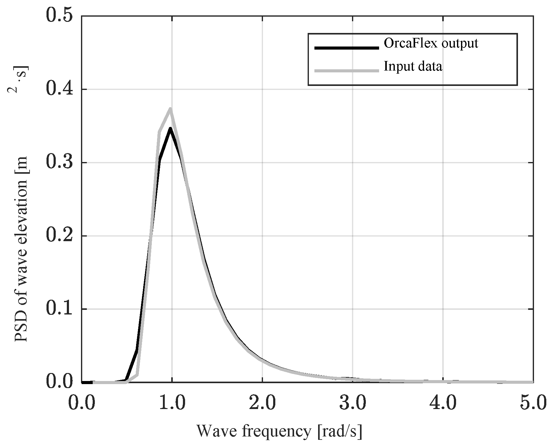
3.2. Irregular Wave Simulations

The regular wave simulation results underscore that the platform’s motion significantly influences the rotor’s motion characteristics. Building upon this, irregular wave simulations were conducted to examine the responses in a real sea environment. The incident wave conditions for these simulations were modeled using the operational design wave of the installation site, as detailed in Table 6 and Figure 13.
To mitigate the initial transient response of the platform, the incident waves were gradually intensified. These conditions were then analyzed over a period of 10,800 s (equivalent to 3 h). Figure 14 presents a time series of the rotor’s angular displacement (relative to the platform [ ξ r e l r t n ] when connected to the platform) under operational conditions for each case. As depicted in Figure 15, these time series data were converted into power spectral density to facilitate a reasonable comparison of motion responses.
Figure 14b reveals that the behavior of the single rotor and the behavior in case 1 (four-rotor case) are similar. However, the results for case 2 (fixed platform case) exhibit different motion patterns, even under identical incident wave conditions. As shown in Figure 7 and Table 5, the initial positions of the rotors in the x-direction differ between cases 1 and 2 based on the global coordinates. In other words, even if the same wave approaches, the timing of encountering the wave varies due to the difference in location. However, as can be seen in Figure 15, the motion spectra of the two scenarios are almost similar. Since this represents the response in the regular wave simulation well (Figure 10), it is judged that the results of the 3 h simulation sufficiently reflect the characteristics of each scenario. The initial positions of the rotors in case 2 and case 3 (floating platform case) are identical, yet the trend in the rotor pitch differs between the two scenarios, influenced by the behavior of the floating platform.
The findings in Figure 15 are similar to the regular wave simulation results. While the response of multiple rotors or rotors connected to a fixed platform did not significantly differ from that of a single rotor, the peak response increased significantly when the rotors were connected to a moving (floating) platform. As observed in Figure 11, the peak frequency of the rotor in case 3 shifted marginally to a lower frequency compared to other scenarios. This shift coincides with the peak frequency area of the incident wave, resulting in rotor resonance. Due to the platform’s behavior, the response around 0.6 rad/s also varied from other cases. In addition, all four cases exhibited a response in the low-frequency region (less than 0.3 rad/s), suggesting that this low-frequency response occurs irrespective of the platform’s presence or the arrangement of multiple rotors. In the low-frequency range, a response was observed even in the absence of significant wave energy (Figure 13), likely due to the nonlinear restoring moment (see Figure 5) applied to the rotor. Subsequently, the rotor’s angular velocity (relative to the platform [ ξ ˙ r e l r t n ] when connected to the platform) was calculated. The power extracted from the nth rotor’s motion was computed using Equation (12) (Figure 16), employing a linear PTO damping coefficient ( b P T O ) of 33.65 (kN·m)/(rad/s) derived from previous studies. For a quantitative comparison, the time-averaged power of the entire system was determined by integrating over the period T , as defined in Equation (13). The results from each case were then compared, as outlined in Table 7.
P r t n t = b P T O × ξ ˙ r e l r t n 2
P ¯ = r o t o r 1 T 0 T P r t n t d t
Table 7 presents the rate of change in power generation, defined as the ratio of the power generated in each scenario to that produced by a single rotor. When compared to the power extracted by a single rotor, the power generated by four rotors shows an increase of approximately 1.86%. Incorporating a truss-structured platform comprising two lower pontoons results in a 4.45% increase in power generation. Table 8 details the average of the absolute value of relative angular velocity for the rotor in each case. Notably, case 3 exhibits a higher velocity compared to the other scenarios. In comparison to the single-rotor scenario, the outer and inner rotors experienced increases in relative velocity of 16.46% and 15.32%, respectively. Additionally, the time-averaged extraction power shows an improvement of approximately 29%. This suggests that in our model, the hydrodynamic interaction and coupled motions between the platform and the rotors contribute positively to the overall power generation efficiency. In the integrated floating platform model, the effects of coupled motion, which are not present in a rotor connected to a fixed rotational axis, become evident. Therefore, analyzing the rotor as if it were connected to a fixed axis poses a risk of underestimating or overestimating the extraction power potential of the actual floating model. This underlines the importance of considering the dynamic interactions between the platform and rotors in assessing power generation efficiency in wave energy systems.

4. Conclusions

In this study, we explored the motion and power generation performance of a Salter’s duck-shaped rotor and platform, modeled as a multi-degree-of-freedom system, under wave conditions. The motion responses and power generation performance of both the rotor and the floating platform were evaluated through a dynamic analysis in the time domain. The following conclusions were drawn:
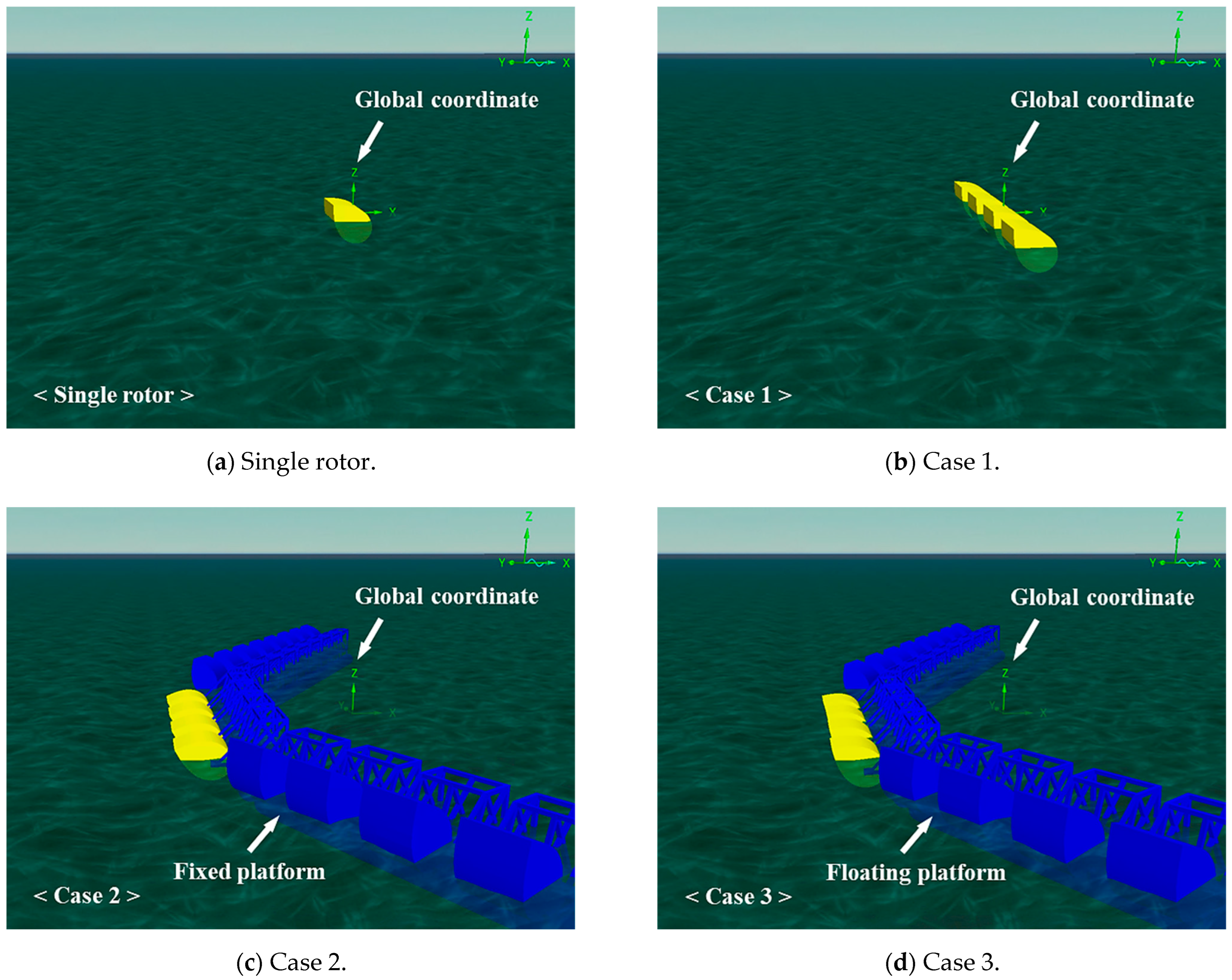
  • Several scenarios were analyzed to understand the hydrodynamic interaction between the floating platform and rotors: a single rotor, an array of four rotors (case 1), rotors connected to a fixed platform (case 2) and a scenario allowing for the movement of the connected platform (case 3). The arrangement of four rotors facilitated a comparison of radiation and diffraction effects. Connecting the rotor to a fixed platform highlighted the hydrodynamic interaction between the platform structure and the rotor. Allowing for platform movement provided insights into the system’s performance under operational conditions.
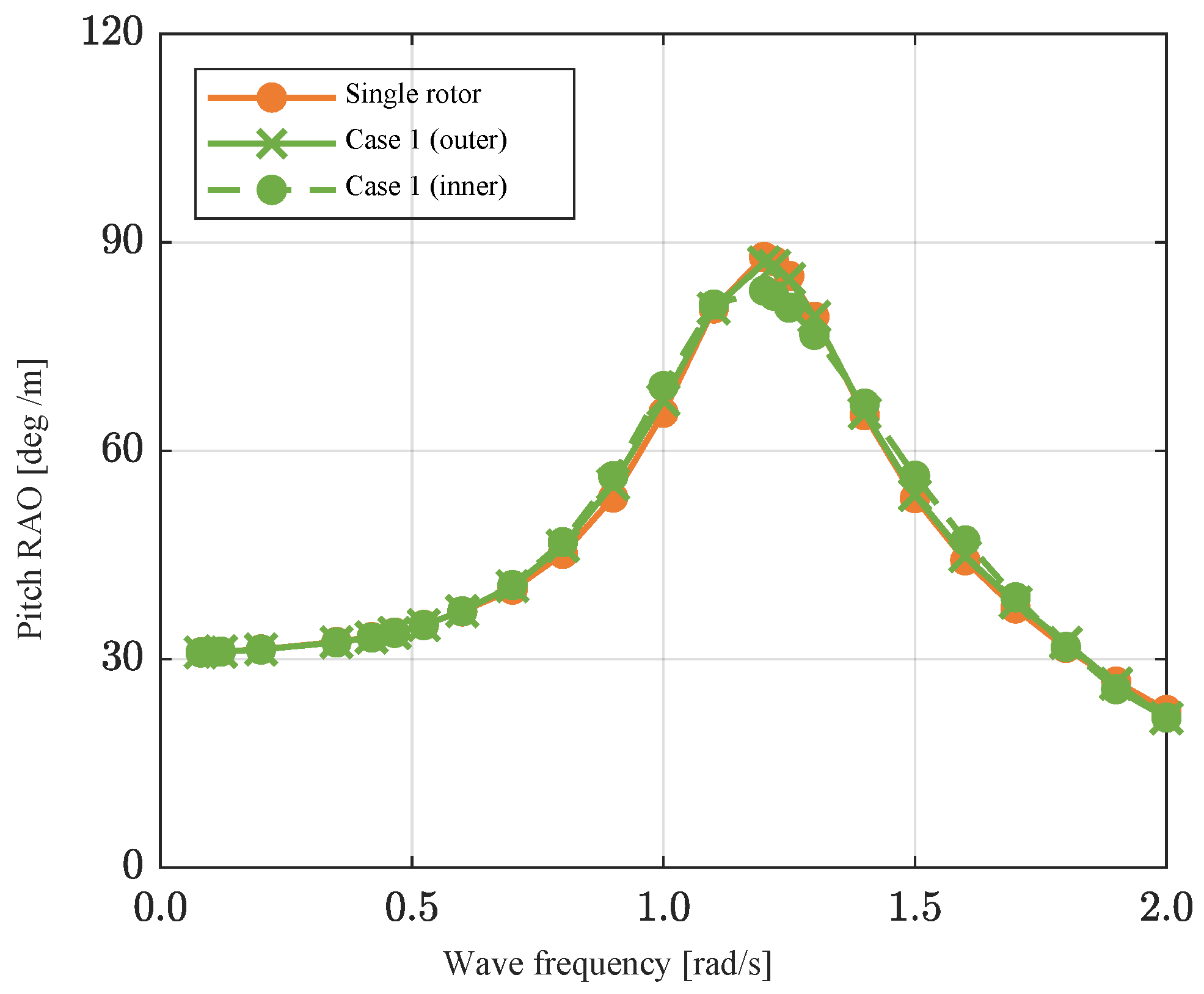
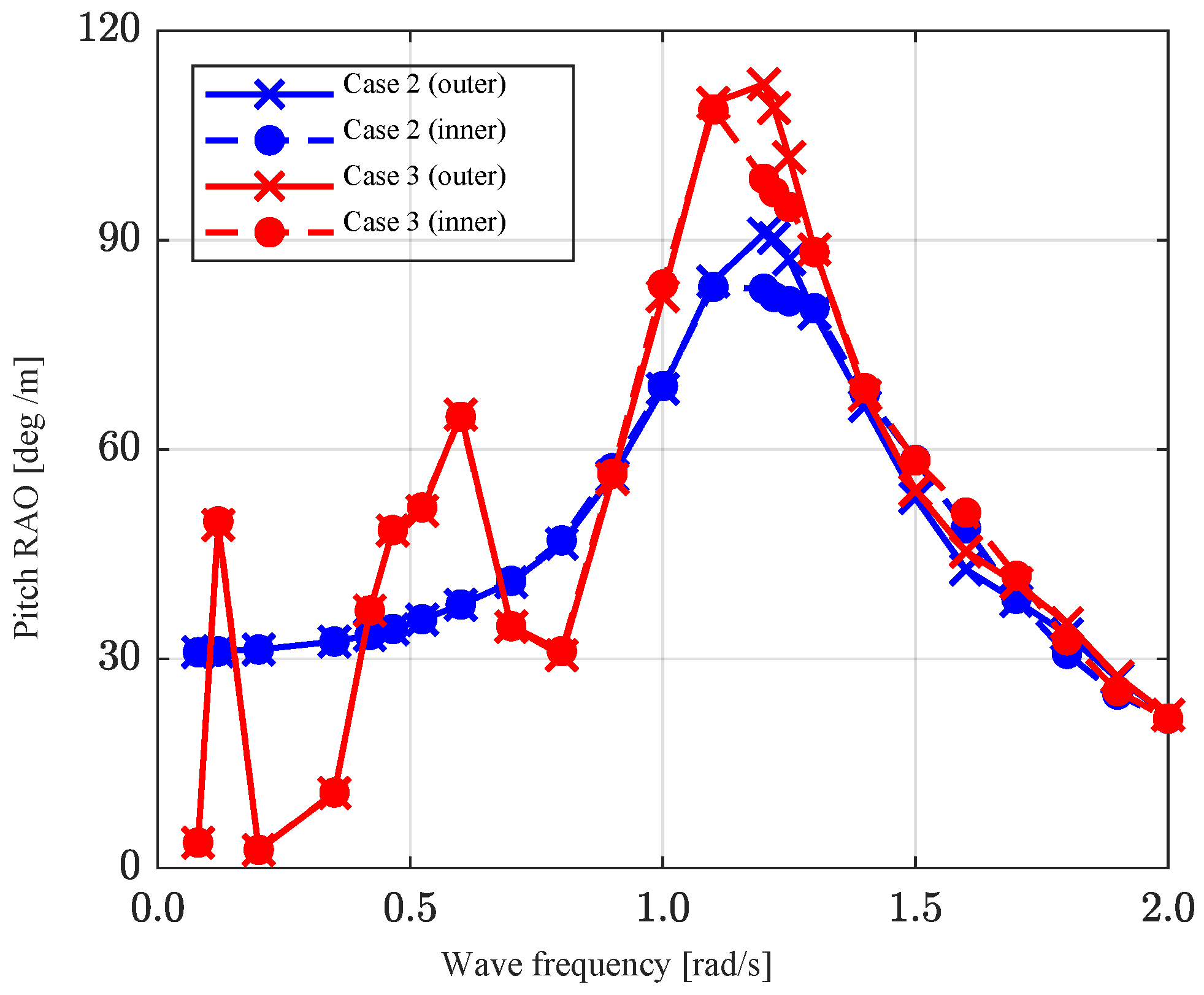
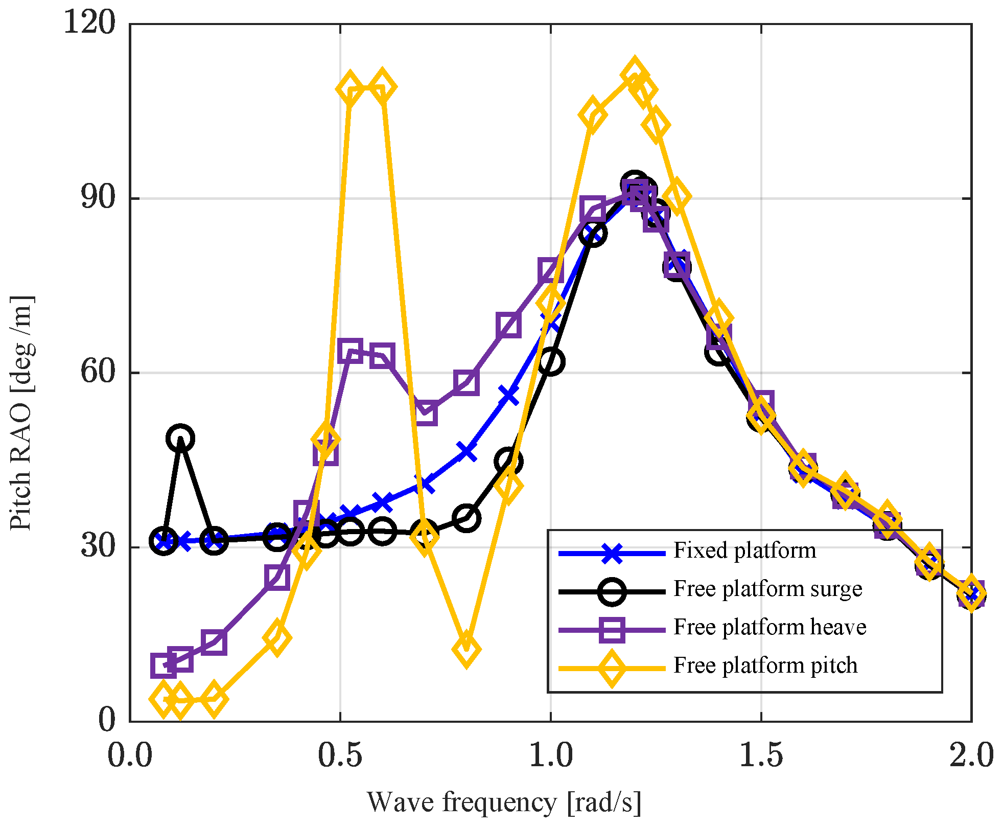
  • Regular wave simulations, conducted at a relatively low wave height of 0.1 m for various incident wave frequencies, aimed to characterize the rotor’s behavior, assuming it operated as a linear system. The results from case 1 indicated differences in motion between inner and outer rotors due to their arrangement. Case 2 demonstrated the influence of platform pontoons on rotor behavior. However, the differences observed in these two scenarios were minor. In contrast, the motion response of the rotor changed significantly when connected to a floating platform, with the main peak frequency shifting marginally to the low-frequency region and the emergence of two peak responses in regions outside the natural frequency range. The floating platform’s heave and pitch motions substantially impacted the rotor’s behavior.
  • Irregular wave simulations under operational conditions were conducted to assess the rotor’s performance when connected to a floating platform in real sea conditions. Time series data from a 3 h simulation were converted into power spectra for comparison. The results from the three cases (single rotor, case 1 and case 2) were generally similar. However, case 3 exhibited a higher peak value and a significant response at approximately 0.6 rad/s. The peak frequency of the rotor, approximately 1.22 rad/s, shifted marginally to the low-frequency region when connected to a floating platform. Considering that the peak frequency of the incident wave (operating condition) was 0.945 rad/s (6.65 s), the rotor operated close to resonance. Additionally, the inherent pitch motion of the rotor caused by wave forcing was combined with the pitch response derived from the heave and pitch of the platform, increasing the response in a specified wave frequency range.
  • Compared to the power extracted by a single rotor under operating conditions, the power generated in case 1 and with rotors connected to a fixed platform increased by approximately 1.86% and 4.45%, respectively. Allowing for the platform’s degree of freedom resulted in a power increase of more than 29%. Although the trend in results may vary depending on the hydrodynamic characteristics of the platform and WECs, the case in this study demonstrated a positive influence on the efficiency of power generation. In other words, examining the rotor under the assumption of a fixed axis poses the risk of either underestimating or overestimating the extraction power potential of the actual floating model. This underscores the importance of considering the dynamic interactions between the floating platform and rotors as essential factors when assessing the efficiency of power generation in real systems.

Author Contributions

Conceptualization, Y.H.B.; methodology, D.K. and Y.H.B.; software, D.K.; validation, D.K. and Y.H.B.; formal analysis, D.K.; investigation, D.K.; resources, Y.H.B.; data curation, Y.H.B.; writing—original draft preparation, D.K.; writing—review and editing, Y.H.B.; visualization, D.K.; supervision, Y.H.B.; project administration, Y.H.B.; funding acquisition, Y.H.B. All authors have read and agreed to the published version of the manuscript.

Funding

This work was supported by the Hongik University New Faculty Research Support Fund.

Institutional Review Board Statement

Not applicable.

Informed Consent Statement

Not applicable.

Data Availability Statement

Dataset available on request from the authors.

Conflicts of Interest

The authors declare no conflicts of interest.

References

  1. Butterfield, S.; Musial, W.; Jonkman, J.; Sclavounos, P. Engineering Challenges for Floating Offshore Wind Turbines; Technology Report; National Renewable Energy Lab (NREL): Golden, CO, USA, 2007. Available online: https://www.osti.gov/servlets/purl/917212 (accessed on 27 December 2023).
  2. Salter, S.H.; Jeffrey, D.C.; Taylor, J.R.M. First Year Interim Report on Edinburgh Wave Power Project: Study of Mechanisms for Extracting Power from Sea Waves; University of Edinburgh: Edinburgh, UK, 1975; Available online: http://hdl.handle.net/1842/23409 (accessed on 27 December 2023).
  3. Jeffrey, D.C.; Richmond, D.J.E.; Salter, S.H.; Taylor, J.R.M. Second Year Interim Report on Edinburgh Wave Power Project: Study of Mechanisms for Extracting Power from Sea Waves; University of Edinburgh: Edingburg, UK, 1976. [Google Scholar]
  4. Evans, D.V. A theory for wave-power absorption by oscillating bodies. J. Fluid Mech. 1976, 77, 1–25. [Google Scholar] [CrossRef]
  5. Count, B.M. On the dynamics of wave-power devices. Proc. R. Soc. Lond. Ser. A Math. Phys. Sci. 1978, 363, 559–579. [Google Scholar] [CrossRef]
  6. Poguluri, S.K.; Bae, Y.H. A study on performance assessment of WEC rotor in the Jeju western waters. Ocean Syst. Eng. 2018, 8, 361–380. [Google Scholar] [CrossRef]
  7. Poguluri, S.K.; Cho, I.H.; Bae, Y.H. A study of the hydrodynamic performance of a pitch-type wave energy converter-rotor. Energies 2019, 12, 842. [Google Scholar] [CrossRef]
  8. Kim, D.; Poguluri, S.K.; Ko, H.S.; Lee, H.; Bae, Y.H. Numerical and experimental study on linear behavior of salter’s duck wave energy converter. J. Ocean Eng. Technol. 2019, 33, 116–122. [Google Scholar] [CrossRef]
  9. Kim, D.; Poguluri, S.K.; Bae, Y.H. Numerical study on linear behavior of arrayed pitch motion wave energy converters. J. Korean Soc. Coast. Ocean. Eng. 2020, 23, 269–276. [Google Scholar] [CrossRef]
  10. Mavrakos, S.A. Hydrodynamic coefficients for groups of interacting vertical axisymmetric bodies. Ocean Eng. 1991, 18, 485–515. [Google Scholar] [CrossRef]
  11. Mclver, P. Wave Forces on Arrays of Floating Bodies. J. Eng. Math. 1984, 18, 273–285. [Google Scholar] [CrossRef]
  12. Taghipour, R.; Moan, T. Efficient frequency-domain analysis of dynamic response for the multi-body wave energy converter in multi-directional wave. In Proceedings of the 18th International Offshore and Polar Engineering Conference, Vancouver, BC, Canada, 6–11 July 2008. [Google Scholar]
  13. Sinha, A.; Karmakar, D.; Soares, C.G. Performance of optimally tuned arrays of heaving point absorbers. Renew. Energy 2016, 92, 517–531. [Google Scholar] [CrossRef]
  14. Poguluri, S.K.; Kim, D.; Ko, H.S.; Bae, Y.H. Performance analysis of multiple wave energy converters due to rotor spacing. J. Ocean. Eng. Technol. 2021, 35, 229–237. [Google Scholar] [CrossRef]
  15. Heo, K.; Choi, Y.R. Numerical investigation of multi-body wave energy converters’ configuration. J. Ocean Eng. Technol. 2022, 36, 132–142. [Google Scholar] [CrossRef]
  16. Kim, H.; Min, E.-H.; Heo, S.; Koo, W. Motion analysis of a wind-wave energy TLP platform considering second-order wave forces. J. Ocean Eng. Technol. 2022, 36, 390–402. [Google Scholar] [CrossRef]
  17. Konispoliatis, D.N.; Mavrakos, S.A.; Katsaounis, G.M. Theoretical evaluation of the hydrodynamic characteristics of arrays of vertical axisymmetric floater of arbitrary shape in front of a vertical breakwater. J. Mar. Sci. Eng. 2020, 8, 62. [Google Scholar] [CrossRef]
  18. Muliawan, M.J.; Karimirad, M.; Moan, T. Dynamic response and power performance of a combined spar-type floating wind turbine and coaxial floating wave energy converter. Renew. Energy 2013, 50, 47–57. [Google Scholar] [CrossRef]
  19. Zhou, B.; Hu, J.; Jin, P.; Sun, K.; Li, Y.; Ning, D. Power performance and motion response of a floating wind platform and multiple heaving wave energy converters hybrid system. Energy 2023, 265, 126314. [Google Scholar] [CrossRef]
  20. Zhou, B.; Hu, J.; Zhang, Q.; Wang, L.; Jing, F.; Collu, M. Optimal design and performance analysis of a hybrid system combining a semi-submersible wind platform and point absorbers. J. Mar. Sci. Eng. 2023, 11, 1190. [Google Scholar] [CrossRef]
  21. Kamarlouei, M.; Gaspar, J.F.; Calvario, M.; Hallak, T.S.; Mendes, M.J.G.C.; Thiebaut, F.; Guedes Soares, C. Experimental analysis of wave energy converters concentrically attached on a floating offshore platform. Renew. Energy 2020, 152, 1171–1185. [Google Scholar] [CrossRef]
  22. Ghafari, H.R.; Ghassemi, H.; He, G. Numerical study of the Wavestar wave energy converter with multi-point-absorber around DeepCwind semisubmersible floating platform. Ocean Eng. 2021, 232, 109177. [Google Scholar] [CrossRef]
  23. Cheng, Y.; Dai, S.; Dai, S.; Ji, C.; Collu, M.; Yuan, Z.; Incecik, A. Energy conversion and hydrodynamic analysis of multi-degree-of-freedom wave energy converters integrated into a semi-submersible platform. Energy Convers. Manag. 2022, 252, 115075. [Google Scholar] [CrossRef]
  24. Yazdi, H.; Ghafari, H.R.; Ghassemi, H.; He, G.; Karimirad, M. Wave power extraction by multi-Salter’s duck WECs arrayed on the floating offshore wind turbine platform. Energy 2023, 278, 127930. [Google Scholar] [CrossRef]
  25. Swift-Hook, D.T.; Count, B.M.; Glendenning, I.; Salter, S. Characteristics of a rocking wave power device. Nature 1975, 254, 504–506. [Google Scholar] [CrossRef]
  26. Cummins, W. The Impulse Response Function and Ship Motions; David Taylor Model Basin: Washington, DC, USA, 1962. [Google Scholar]
  27. WAMIT, Inc. Available online: https://www.wamit.com (accessed on 27 December 2023).
  28. AeroHydro, Inc. Available online: https://aerohydro.com/ahi_products/multisurf (accessed on 27 December 2023).
  29. Journée, J.M.J.; Massie, W.W. Offshore Hydromechanics; Delft University of Technology: Delft, The Netherlands, 2001. [Google Scholar]
  30. Orcina, Ltd. Available online: https://www.orcina.com/orcaflex (accessed on 27 December 2023).
Figure 1. Location where the rotor was installed and operated (western sea of Jeju, South Korea).
Jmse 12 00265 g001
Figure 2. Schematic of the rotor and platform.
Jmse 12 00265 g002aJmse 12 00265 g002b
Figure 3. Schematic of the mooring buoy and cable system.
Jmse 12 00265 g003
Figure 4. Details of the submerged part of the rotor and platform.
Jmse 12 00265 g004aJmse 12 00265 g004b
Figure 5. Restoring moment of the rotor as a function of angular displacement.
Jmse 12 00265 g005
Figure 6. RAOs of platform and single rotor in regular waves (wave height = 0.1 m).
Jmse 12 00265 g006
Figure 7. Numerical model of rotor and platform in OrcaFlex.
Jmse 12 00265 g007
Figure 8. Configuration of arrayed rotors on the central platform.
Jmse 12 00265 g008
Figure 9. Pitch RAO of rotors in regular waves for analyzing the effect of multiple rotors.
Jmse 12 00265 g009
Figure 10. Pitch RAO of rotors in regular waves for analyzing the effect of a fixed platform.
Jmse 12 00265 g010
Figure 11. Pitch RAO of rotors in regular waves for analyzing the effect of a floating platform.
Jmse 12 00265 g011
Figure 12. Pitch RAO of the outer rotor based on the platform’s limited degree of freedom conditions.
Jmse 12 00265 g012
Figure 13. Power spectral density of the incident wave (JONSWAP Spectrum, H s = 2.0   m , T p = 6.65   s , γ = 1.0 ) .
Jmse 12 00265 g013
Figure 14. Time series of rotor pitch angular displacement.
Jmse 12 00265 g014
Figure 15. Power spectral density (PSD) of rotor pitch angular displacement (over a 3 h period).
Jmse 12 00265 g015
Figure 16. Time series of rotor pitch angular velocity and extracted power.
Jmse 12 00265 g016
Table 1. Specifications of the single rotor.
ItemUnitValue
Mass k g 21,346
Center of gravity with respect to CoR (1) m (−0.89, 0, 1.017)
Moment of inertia (pitch) with respect to CoR k g · m 2 117,369
Depth of rotational axis m 1.60
Diameter of hole m 3.60
Radius of stern m 2.00
Width m 5.00
Undamped natural period (pitch) s 5.13
(1) CoR: center of rotation.
Table 2. Specifications of the platform.
ItemUnitValue
Mass k g 2,327,975
Vertical length of CoG (1) below SWL (2) m −1.87
Moment of inertia (roll) with respect to CoG k g · m 2 5,433,070,351
Moment of inertia (pitch) with respect to CoG k g · m 2 318,305,735
Moment of inertia (yaw) with respect to CoG k g · m 2 5,708,240,092
Draft m 5.35
Diameter of pontoon m 2.70
Length of the central platform’s pontoonm34.0
Length of the wing platform’s pontoonm68.0
Undamped natural period (surge) s 50.00
Undamped natural period (heave) s 12.00
Undamped natural period (pitch) s 13.50
(1) CoG: center of gravity; (2) SWL: still water level.
Table 3. Damping ratio values of the platform and rotor.
PlatformRotor
Degree of FreedomSurgeHeavePitchPitch
Damping ratio ( κ ) 0.00170.15390.04320.0906
Table 4. Case classification for multibody analysis.
ScenarioNumber of RotorsPlatform Type
Single rotor1 EAWithout platform
Case 14 EAWithout platform
Case 24 EAFixed platform
Case 34 EAFloating platform
Table 5. Initial position for each body coordinate system.
Coordinate SystemPosition with Respect to Global Coordinates [m]
Global(0, 0, 0)
Single rotor
Single rotor(0, 0, 0)
Case 1
Outer rotor 1(0, −12.75, −1.6)
Inner rotor 1(0, −4.25, −1.6)
Inner rotor 2(0, 4.25, −1.6)
Outer rotor 2(0, 12.75, −1.6)
Cases 2 and 3
Platform(0, 0, 0)
Outer rotor 1(−20.321, −12.75, −1.6)
Inner rotor 1(−20.321, −4.25, −1.6)
Inner rotor 2(−20.321, 4.25, −1.6)
Outer rotor 2(−20.321, 12.75, −1.6)
Table 6. Environmental conditions (operation).
ParameterUnitValue
Wave spectrum-JONSWAP
Significant wave height ( H s )m2.0
Peak period ( T p )s6.65
Peak enhancement factor ( γ )-1.0
Table 7. Time-averaged extraction power.
Scenario P ¯
[kW]
Rate of Change
[%]
Single rotor × 4EA47.2954-
Arrayed 4 rotors (case 1)48.1761+1.86 ↑ (1)
4 rotors connected to fixed platform (case 2)49.3984+4.45 ↑
4 rotors connected to floating platform (case 3)61.3356+29.69 ↑
(1) The ‘↑’ symbol indicates an increase.
Table 8. Average of the absolute value of relative angular velocity for each case’s rotors.
ScenarioOuter RotorInner Rotor
Mean
[rad/s]
Rate of Change
[%]
Mean
[rad/s]
Rate of Change
[%]
Single rotor0.48-0.48-
Case 10.49+0.85 ↑0.49+1.02 ↑
Case 20.50+2.44 ↑0.50+2.26 ↑
Case 30.56+16.46 ↑0.56+15.32 ↑
Disclaimer/Publisher’s Note: The statements, opinions and data contained in all publications are solely those of the individual author(s) and contributor(s) and not of MDPI and/or the editor(s). MDPI and/or the editor(s) disclaim responsibility for any injury to people or property resulting from any ideas, methods, instructions or products referred to in the content.

