Article

A Vessel Position Precision Analysis Based on a Two-Star Combined Approach

Beijing Aerospace Automatic Control Institute, Beijing 100039, China
*
Author to whom correspondence should be addressed.
J. Mar. Sci. Eng. 2024, 12(12), 2347; https://doi.org/10.3390/jmse12122347
Submission received: 2 December 2024 / Revised: 16 December 2024 / Accepted: 19 December 2024 / Published: 21 December 2024
(This article belongs to the Section Ocean Engineering)

Abstract

:
Traditional celestial navigation mainly utilized the sextant to measure the attitude and the position contour method to calculate and resolve the vessel’s positioning problem, but these methods are not rigorous, having major deficiencies in the positioning accuracy. Currently, the small field-of-view star sensor is becoming the main attitude measurement equipment on vessels, and its measurement accuracy directly affects the vessel positioning results. Aiming at this problem, this research provides a model of small field-of-view star sensor positioning accuracy based on the two-star combination method, and numerical solutions are given. In addition, it focuses on the influence of the measurement error of the star sensor, especially the elevation angle error, on the positioning accuracy of the vessel and gives the star selection strategy for practical application. In particular, the star selection strategy is also applicable to other two-star positioning methods. The results show that the analytical solution is computationally simple and real-time, and the effect of measurement errors on positioning can be minimized by the star selection strategy. This study reveals the error influence mechanism based on the dual-star combination approach, which has significant implications for practical vessel navigation using small-field-of-view star sensors.

1. Introduction

Early celestial navigation was primarily employed for maritime purposes, utilizing the sextant as the primary instrument for celestial measurements [1]. The position contour method was used to calculate a vessel’s latitude and longitude; however, this approach lacked accuracy. As maritime technology has advanced, the demand for precise navigation information has increased. The determination of vessel navigation parameters has thus become a critical technology in the field of navigation [2]. Currently, the Global Navigation Satellite System (GNSS) is the most widely used navigation system. However, this method heavily depends on satellite resources. While GNSS holds a significant advantage in terms of navigation accuracy and cost-effectiveness, it presents substantial potential issues in reliability and security, making it unsuitable as the sole core navigation system. In contrast, inertial navigation and celestial navigation are the only two autonomous navigation systems capable of providing global coverage without relying on external information. Therefore, the utilization of star sensor/inertial navigation techniques ensures autonomous positioning of vessels at any moment in time while underway. Initially, star sensor/inertial navigation system (INS) combined systems were primarily utilized for maritime navigation [3]. In these systems, the accumulated errors of the INS could be corrected and suppressed using data from star sensors, thereby improving navigation accuracy. However, early star sensors exhibited relatively low precision due to developmental limitations [4], which led to inadequate system error suppression. Recent advancements in optical sensor technology and image processing have led to significant improvements, and research into the algorithms for star sensor-based positioning and attitude determination has become more sophisticated. Consequently, star sensor/INS combined navigation systems are now more widely applied in maritime navigation.
A shipborne small-field-of-view star sensor is an attitude measurement device that determines a vessel’s precise attitude by capturing images of celestial bodies [5]. Due to factors such as atmospheric reflection/refraction and dust scattering, the star sensing capability of the star sensor system is significantly diminished during daylight. To address this issue, the field of view of the star sensor system must be reduced, enabling higher-resolution star maps to be obtained from a narrower field, which allows for the more accurate extraction of stellar information. However, the small field of view of these sensors means that they can only observe a small portion of the sky at a time, typically tracking 1–2 navigational stars simultaneously. This limitation also results in a high dependence on an accurate star catalog database. When measurements are taken with a small-field-of-view star sensor, information such as right ascension, declination, azimuth, and elevation of the navigational stars is typically obtained. These measurements usually lack a true value for comparison; therefore, the precision of the star sensor is generally evaluated based on the stability of repeated measurements.
The celestial positioning relies on the information measured by the star sensor, which is localized by an equinoctial circle formed by one, two, or more stars [6]. Specifically, the positioning methods determine the vessel’s position by drawing a circle with the substellar point as the center and the zenith distance as the radius. A single equal-altitude circle alone cannot uniquely determine the position of the vessel. Thus, the double-star method is the most extensively studied and widely applied approach. Historically, researchers have used closed-form analytical solutions to address the double-star aiming problem in celestial positioning. Depending on the solution method, two-star astronomy-based positioning can be broadly classified into three groups: deterministic solution methods, projection methods, and other optimization methods. The first group is the deterministic solution methods for two-star problems, including the spherical triangle method [7], the vector method [8], and the closed analytic solution method [9,10]. Such methods solve the positioning equations directly, with the advantage that it is not dependent on any a priori knowledge and can be solved directly; with the disadvantage that sometimes the solution is too complicated. The second group is the projection methods based on a priori position information, including the traditional table lookup method [11], intercept method [12], and iterative method [13]. All these methods require current position extrapolation from the initial value, so it is necessary to choose a suitable initial value, otherwise it will affect the calculation accuracy. The third group includes other optimization methods, including the least squares method [14], particle swarm method [15,16], genetic algorithm (GA) [17], robust estimation method [18], and so on [19]. These methods need to be optimized through iterations and usually require more time. To summarize, all currently used two-star positioning methods have inherent drawbacks, including overly complex solution representations and time-consuming solutions.
In addition, the current two-star positioning methods focus on finding a generalized solution and do not pay enough attention to the mechanism by which the elevation angle error affects the positioning and do not select the navigating star or only perform a simple filtering of the elevation angle in the calculation. For example, ref. [15] states that the positioning error becomes larger when the observed elevation angle of the celestial body exceeds 70 degrees. However, the method only considers the large measurement error of the star sensor when the elevation angle is too large and does not consider that the error of a particular combination of elevation angles when using contour circles for positioning can cause a drastic change in the positioning error. Therefore, it is necessary to study the mechanism of the influence of the elevation angle error on the positioning results and to guide the navigation star selection through a defined strategy.
In order to solve the problems of the former two-star positioning methods and complete the high-precision two-star positioning analysis, we firstly study the solution process of the two-star positioning equation, which gives the analytical solution with clear physical meaning and simple expression. This solution process takes a very short time and has high real-time performance. We propose a generalized star selection strategy through the analysis, which selects the navigation star through the relationship between the elevation angle and the angular distance of the star, which suppresses the great influence of the elevation angle error on the positioning at a specific position and increases the credibility of the two-star positioning results. The detailed analysis process is given below.

2. Positioning Model Based on the Two-Star Combination Method

The fundamental concept of two-star positioning based on equal-altitude circles is as follows: Astronomical observation equipment measures the elevation angle of celestial bodies to obtain their positional information. By taking the substellar point of a celestial body as the center and the zenith distance as the radius, an equal-altitude circle can be drawn. Since the starlight is considered parallel, the zenith distance observed at any point on the equal-altitude circle is the same. A single equal-altitude circle alone cannot determine the vessel’s position [9]. Therefore, by observing multiple celestial bodies with the astronomical observation equipment on the vessel, two or more equal-altitude circles can be obtained, and the intersection of these circles provides the vessels’ geographical location.
In this study, the star sensor is installed on a vessel and is combined with an INS to determine the vessel’s position. The coordinate systems involved are defined as follows:
  • Star Sensor Base Coordinate System (s-system): This is the coordinate system fixed to the star sensor.
  • Vessel Coordinate System (b-system): This system is theoretically fixed to the vessel but may have installation errors.
  • Geographical Coordinate System (n-system): This system is aligned with geographical coordinates.
  • Earth-Centered Inertial Coordinate System (i-system): This system is aligned with the Earth-centered inertial frame.
  • Earth-Centered Fixed Coordinate System (e-system): This system is aligned with the fixed frame relative to the Earth.
In maritime navigation, using the two-star positioning method, at least the positions of two stars are required. The key observational quantities are the azimuth angle, elevation angle, right ascension, declination, and the Greenwich Hour Angle (GHA).
Assuming the right ascension, declination, and elevation angle of the navigational star j are given by α j , δ j , E l j , respectively, and letting the zenith distance be Z e n j = 90 E l j , according to the fundamental principles of astronomical navigation [20], the star’s vector in the i-system can be represented as:
r i = cos α j cos δ j sin α j cos δ j sin δ j
Since the two-star positioning is performed in the geographical coordinate system, it is necessary to convert the star’s vector into the n-system.
r n = C e n C i e r i
The transformation matrix C e n from the e-system to the n-system depends only on the local latitude and longitude [21]. Let the local longitude be λ and the local latitude be L. Then, the transformation matrix is given by:
C e n = sin ( λ ) cos ( λ ) 0 sin ( L ) cos ( λ ) sin ( L ) sin ( λ ) cos ( L ) cos ( L ) cos ( λ ) cos ( L ) sin ( λ ) sin ( L )
The transformation matrix C i e from the i-system to the e-system depends only on the current time [20], specifically the GHA.
C i e = cos ( g h a ) sin ( g h a ) 0 sin ( g h a ) cos ( g h a ) 0 0 0 1
In the n-system, the position of the vessel P is expressed in spherical coordinates as l o c = x y z . From the geometric relationships of the two-star positioning, it can be derived that:
l o c · r n = cos ( Z e n j )
Let a j = cos α j cos δ j b j = sin α j cos δ j c j = sin δ j d j = cos ( Z e n j ) .
Then, the above expression can be written as
a 1 x + b 1 y + c 1 z = d 1 a 2 x + b 2 y + c 2 z = d 2
By using the method of elimination, it can be derived that
( a 1 b 2 a 2 b 1 ) y + ( a 1 c 2 a 2 c 1 ) z = a 1 d 2 a 2 d 1 ( a 2 b 1 a 1 b 2 ) x + ( b 1 c 2 b 2 c 1 ) z = b 1 d 2 b 2 d 1
Then, the above expression can be written as
A y + B z = C A x + D z = E
where A , B , C , D , and E are all known. Since P is on the sphere, there is x 2 + y 2 + z 2 = 1 . By solving the three simultaneous equations, an analytical solution can be obtained.
x = A 2 E B 2 E + B C D D · Q A ( A 2 + B 2 + D 2 ) y = A 2 C B D E + C D 2 ± B · Q A ( A 2 + B 2 + D 2 ) z = B C + D E Q A 2 + B 2 + D 2
where Q = A 4 + A 2 B 2 A 2 C 2 + A 2 D 2 A 2 E 2 B 2 E 2 + 2 B C D E C 2 D 2 .
The analytical solution for ( x , y , z ) appears quite complex. However, once the celestial information is determined, A , B , C , D , and E are all fixed, and it becomes straightforward to substitute into the formula to obtain the solution. Although the analytical solution is easy to obtain, due to the high coupling of zenith distance with right ascension and declination, it is not possible to separately calculate the effect of each variable on the position.

3. Positioning Accuracy Model

3.1. Positioning Accuracy Model

Solving the two-star positioning model requires the right ascension and declination of the stars and the elevation angle in the n-system. During the actual measurement process of the star sensor, the changes in the star’s right ascension and declination are very small over short periods and can be considered negligible. The elevation angle measured by the star sensor is in the s-system, while two-star positioning is calculated in the n-system. Therefore, the errors in the two-star positioning model mainly arise from the measurement errors in the elevation angle by the star sensor and the conversion errors of the elevation angle between different coordinate systems.
When considering positioning accuracy, it is necessary to first convert the elevation angle measured by the star sensor to the elevation angle in the n-system. Assuming the star vector in the s-system is represented as r s , then the star vector in the n-system can be represented as r n .
r n = C b n C s b r s = C b n C s b cos ( E l s ) sin ( A z s ) cos ( E l s ) cos ( A z s ) sin ( E l s )
where C b n represents the transformation matrix from the b-system to the n-system. This matrix is typically provided by the INS fixed to the star sensor and is calculated using roll, pitch, and heading angles. C s b represents the installation error between the star sensor and the INS.
From Equation (10), it can be seen that precise calibration of the INS must be completed prior to two-star positioning [22]. This ensures that the INS maintains high-precision sensitivity to the vessel’s attitude throughout the measurement process. Additionally, the calibration experiment between the INS and the star sensor is required to obtain accurate values of the installation errors [23].
The altitude angle in the n-system can be expressed as
E l n = arcsin ( r n [ 3 ] )
where r n [ 3 ] denotes the third element of r n . Therefore, the elevation angle in the n-system is related to only three factors: the measured elevation angle in the s-system, the vessel attitude, and the installation error.
Since a vessel-mounted small-field star sensor can measure at most one navigational star at a time, but two-star combination positioning requires the information of two navigational stars at the same moment, interpolation of the elevation angle for a single navigational star is necessary to align the times. In general, the altitude angles of the navigational stars that can be observed vary linearly or quadratically with time, and the two time points are very close to each other at the time of interpolation, so we utilize linear interpolation when interpolating the altitude angles.
In astronomy, the angle between the position vectors of any two celestial bodies is referred to as the angular separation. Let us denote two stars, m and k, with position vectors r m , r k , respectively. The angular separation d between these two stars can be calculated as follows:
d m k = arccos ( r m , r k )
From the two-star positioning model presented in Section 2, it is known that the two circles involved in two-star positioning correspond to the zenith distances in the n-system, which are the complements of the elevation angles. The distance between the centers of these two circles can be expressed in terms of the angular separation between the stars. Therefore, it follows that, when selecting two stars for positioning calculations, the following situations may arise:
Z e n m + Z e n k < d m k Z e n m + Z e n k = d m k Z e n m + Z e n k > d m k Z e n m Z e n k = d m k Z e n m Z e n k > d m k Z e n m Z e n k < d m k
where Z e n m and Z e n k denote the zenith distances of stars m and k in the coordinate n-system, and · represents the absolute value of their difference. It can be observed that:
  • When the angular separation is greater than the difference in zenith distances and less than the sum of the zenith distances, the two circles intersect at two points, resulting in two possible solutions for two-star positioning.
  • When the sum of the zenith distances equals the angular separation, or the absolute difference of the zenith distances equals the angular separation, the two circles are tangent to each other, providing a single solution for two-star positioning.
  • When the sum of the zenith distances is less than the angular separation, or the difference in zenith distances is greater than the angular separation, the two circles do not intersect. In this case, the double-star positioning model has no solution.
As outlined in the two-star positioning error model in Section 2, the numerical solution of the two-star positioning problem is related to the right ascension, declination, and elevation angles in n-system. However, due to the complexity of Equation (9), it is not straightforward to derive the relationship between the elevation angle and the vessel’s position ( x , y , z ) . Consequently, it is also challenging to directly determine the relationship between the elevation angle error and the target point.
The two-star positioning model essentially involves the intersection problem of two circles in three-dimensional space. As time progresses, the right ascension and declination of the two stars change, which means the positions of the two stars and, consequently, the centers of the circles also change. Additionally, the zenith distances, which correspond to the radii of these circles, vary accordingly. Therefore, for two stars, the two-star positioning model can be viewed as a problem of intersecting circles with both varying positions and radii.
To qualitatively illustrate the precision issues in the two-star positioning model, we use circles in a two-dimensional plane to simulate this process. Assume the equations of the two circles are given by:
( x x 1 ) 2 + ( y y 1 ) 2 = R 1 2 ( x x 2 ) 2 + ( y y 2 ) 2 = R 2 2
where ( x 1 , y 2 ) , ( x 1 , y 2 ) are the centers of Circle 1 and Circle 2. R 1 and R 2 are the radii of Circle 1 and Circle 2, respectively.
Similar to the two-star positioning model, we vary the distance between the circle centers and introduce a small error in the radii to observe the changes in the intersection points of the two circles. To simplify and make the process more intuitive, we set x 1 = y 1 = y 2 = 0 and R 1 = 2 , R 2 = 1 .
We control the distance between the circle centers by varying x 2 and introduce errors of 0.01, 0.001, and 0.0001 to the radii R 2 . This allows us to observe how the intersection points of the two circles change with these adjustments.
Given that x 1 is located at ( 0 , 0 ) and y 2 equals 0, it follows that the value of x 2 is equivalent to the distance between the centers of the two circles. Based on the calculations involving the radii of the two circles, it can be deduced that when x 2 is equal to 1, the circles are internally tangent; when x 2 is equal to 3, the circles are externally tangent. For values of x 2 such that 1 < x 2 < 3 , the circles intersect. Outside of the range, the circles do not intersect. As illustrated in Figure 1, when the error in R 2 increases from 0.0001 to 0.1, the positioning error correspondingly increases. At an error of 0.1 in R 2 , the positioning error becomes significantly larger, consistently exceeding 0.1. Conversely, when the errors in R 2 are 0.01, 0.001, or 0.0001, the positioning errors are predominantly within 0.004.
Additionally, when there are small errors in the radii, the error in the intersection points of the two circles varies as the relationship between the circles changes from intersecting internally to intersecting externally. The error initially increases, reaches a peak, and then decreases as the circles transition from intersecting to being tangent, either internally or externally. This indicates that when there is measurement error in the star sensor and the selected two stars are exactly tangent, the positioning error can increase sharply. Therefore, it is essential to explore additional star selection strategies to mitigate this issue.
From the above analysis, it is evident that when two circles intersect and the distance between their intersection points is relatively large, the impact of radius errors (i.e., elevation angle measurement errors from the star sensor) on the intersection points is minimal. Therefore, we propose using the relationship between the zenith distance and the angular separation as an additional star selection strategy. Specifically, before selecting stars, we first compute the values of Z e n m + Z e n k d m k > 5 or Z e n m Z e n k d m k > 5 . Only those navigational stars that satisfy these conditions will be used in the two-star positioning calculation process. We experimentally verified this conclusion, as described in Section 4.

3.2. Algorithm Flow

The process for determining position using the two-star positioning method is as follows:
(1)
Experimental Preparation: Complete the calibration of the INS and the calibration of installation errors between the INS and the star sensor.
(2)
Observation of Navigation Star 1: Obtain the elevation angle, azimuth angle, right ascension, declination, and GHA for the celestial body in the s-system.
(3)
Transformation to Geographical Coordinates: Convert the right ascension and declination to the n-system using the latitude, longitude, and GHA.
(4)
Conversion to Geographical Coordinates: Convert the observed elevation angle to the n-system using the attitude provided by the INS.
(5)
Interpolation of Navigation Star 1 Data: Find the closest available elevation angle information for Navigation Star 1 at the current time and perform secondary interpolation. Since right ascension and declination change very slowly; no interpolation is needed for this.
(6)
Selection of Navigation Star 2: Find Navigation Star 2 between the current time and the interpolation time. Combine Navigation Star 1 and Navigation Star 2, using the observation time of Navigation Star 2 as the reference time.
(7)
Calculation of Angular Separation: Determine the angular separation between Navigation Star 1 and Navigation Star 2.
(8)
Evaluation of Star Separation and Zenith Distance Relationship: Calculate the relationship between the angular separation and the two zenith distances, and evaluate whether Navigation Star 1 and Navigation Star 2 can be combined to complete the two-star positioning.
(9)
Solution Determination: If the conditions are met, solve for the two-star positioning solution. If the conditions are not met, discard this combination and repeat steps 1 through 7.

4. Experiments

4.1. Navigation Star Selection for Simulation Experiment

To conduct a simulation analysis of the positioning error in the two-star optical observation system, it is essential to select appropriate reference navigation stars. For this analysis, we utilize the navigation stars outlined in [9]. This source provides benchmark data on the right ascension, declination, and elevation angles of four navigation stars, along with the relevant observation time and location. The specific information is detailed in Table 1.

4.2. Comparison of Numerical Solution Accuracy with Other Closed Analytic Methods

Accurate calculation of two-star positioning is essential for subsequent error analysis. In order to verify the validity of the analytic solution proposed in Section 2, we compared the method of this paper with the classical method [9] and the latest closed analytic solution method [10], and the results are shown in Table 2. The analytic solution for each pair of star combinations has two results, distinguished by position 1 and position 2. Each position provides the longitude first, followed by the latitude. Additionally, a “+” in the longitude indicates east longitude, while a “−” indicates west longitude. For latitude, “+” indicates north latitude, while “−” indicates south latitude. For example, the position 1 coordinates of the stellar pair Arcturus–Altair are latitude 41.661° N and longitude 91.532° W. In Table 2, due to the limitations of the original references, the James A. Van Allen Method retains three decimal places, while the King-Cheng Tsai Method retains four decimal places.
As shown in Table 2, the differences among the three methods are minimal. To further illustrate these differences, the specific latitude and longitude deviations are provided in Table 3 and Table 4, respectively. Ours-James denotes the difference between the results of our method minus the James A. Van Allen Method. Similarly, Ours-Tsai represents the difference between our method minus the results of the King-Cheng Tsai Method.
It is worth noting that the units of deviation between our method and the other two methods are all in arcseconds. Compared to the James A. Van Allen Method, the maximum latitude deviation is 1.7712 arcseconds. In contrast, the maximum latitude deviation from the King-Cheng Tsai Method is only 0.0384 arcseconds. Considering the effects of rounding errors, it can be concluded that the precision of our method is consistent with that of the King-Cheng Tsai Method.
Compared to the James A. Van Allen Method and the King-Cheng Tsai Method, the maximum longitude deviations are 1.4642 arcseconds and 0.0396 arcseconds, respectively. Therefore, we conclude that the analytical solutions obtained by our method are highly accurate and suitable for further error analysis.

4.3. Simulation Analysis of Positioning Accuracy

In the simulation experiment, we paired the four navigation stars simultaneously. Table 5 outlines the specific combination methods, including the two-circle position, star angular distances, the sum or difference of the zenith angles, and the discrepancies between the zenith distances and star angular distances. Notably, only the combinations of Arcturus–Altair and Arcturus–Vega lie outside the two circles, while the remaining four combinations are situated within the interior of the two circles.
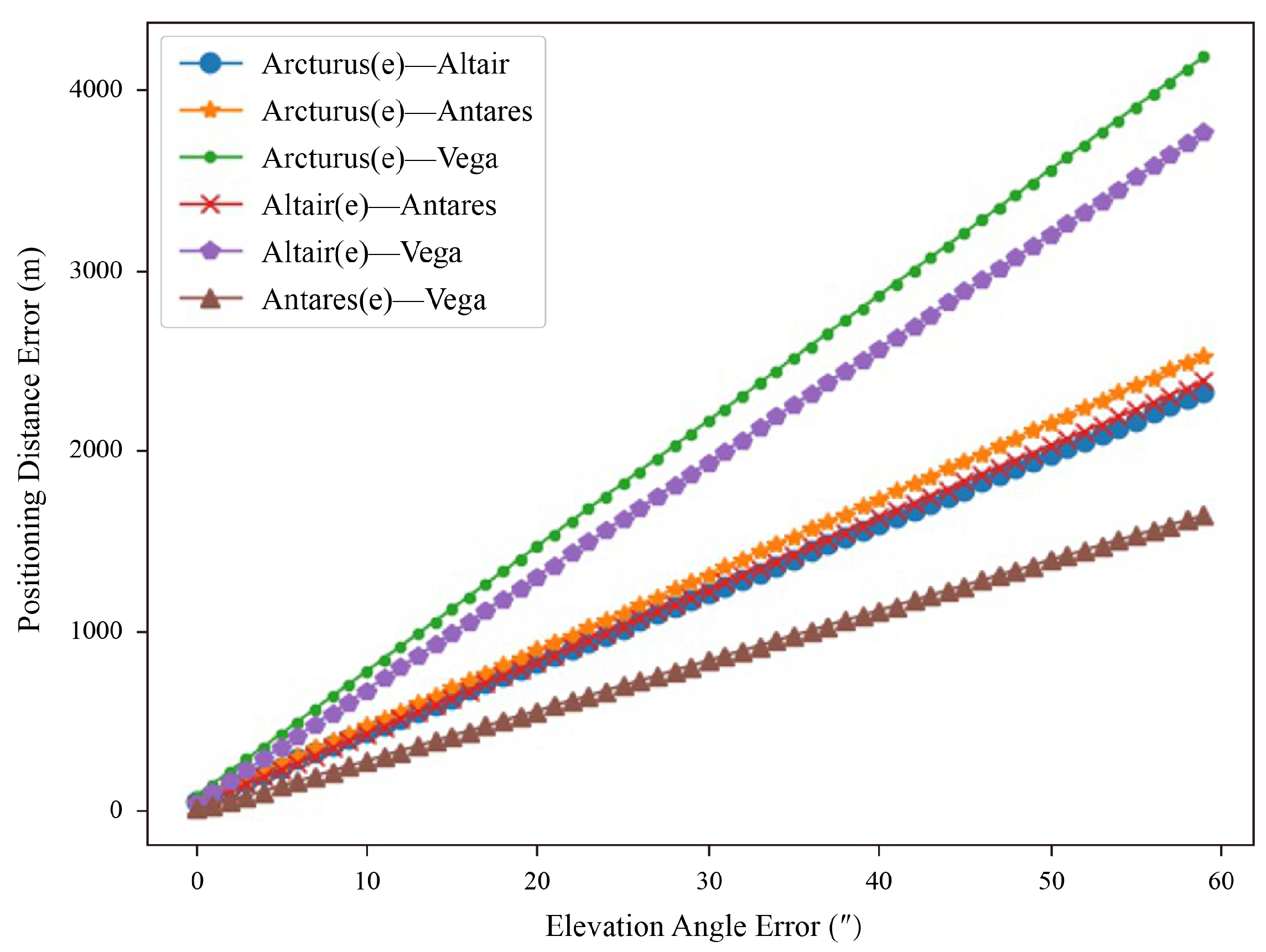
To verify the impact of elevation angle errors on positioning, we systematically introduced errors ranging from 1″ to 60″ to the elevation angle of the specific stars listed in Table 5. We then calculated the resulting erroneous latitude and longitude and determined the actual distance from the observation site. The results are illustrated in Figure 2, where (e) in the legend indicates the star to which the error has been applied.
Figure 2 illustrates that, for the same star combination, an increase in elevation angle error leads to a corresponding increase in positioning error, demonstrating a linear relationship. Additionally, the rate of change in positioning error varies across different star combinations, indicating that positioning error is influenced not only by elevation angle error but also by the spatial relationship between the two circles. For the combinations of Arcturus–Vega and Antares–Vega, Table 5 shows that the differences between the two circles are nearly tangent to each other, resulting in a significant increase in positioning error, consistent with the findings from two-dimensional simulations. Importantly, in practical applications, the combinations of Arcturus–Vega and Antares–Vega would be filtered out by our star selection method.
To further investigate the mechanism by which elevation angle errors affect positioning, we introduced elevation angle errors to each of the two stars in the combinations, as illustrated in Figure 3. The results indicate that, for the same star combination, the variation in positioning error remains largely consistent regardless of which star the errors are introduced into.

4.4. Ground-Based Experiment

To further validate the effectiveness of the method presented in this paper, ground-based experiments were conducted. The star sensor was positioned on an unobstructed rooftop for star observation. The INS and star sensor were accurately calibrated prior to the experiment with reference to [22,23]. The experiment took place on 3 May 2024, in Beijing, at geographical coordinates of (116.25° E, 39.91° N). During the 440 min test period, the entire test system remained stationary, and the attitude of the star sensor was provided by INS. Additionally, the weather conditions were favorable, with clear skies and no cloud cover, making it ideal for stargazing. In the empirical data, numerical identifiers represent different navigation stars, and the positioning error was calculated following the procedures outlined in Section 3.2.
Under ideal conditions, the star sensor’s position should remain constant throughout the experiment, and the two-star observation positioning outcomes would align perfectly with the experimental location. However, measurement errors inherent to the star sensor result in a positioning error. During the ground experiments, we use a navigation star catalog containing 80 stars, numbering the different navigation stars with the numbers 1–80, and the star sensor tracks these stars during its operations and gives the corresponding measurements. In the illustrations of all ground experiments, the numerical values in the legend correspond to star combinations, with our convention of listing the lower number first. When the star number combination is a three-digit number, the first digit is a star, while the last two digits indicate another star. Additionally, when the star number combination is four digits, the first two digits and the last two digits indicate two star numbers, respectively. For example, 115 indicates a pairing of star 1 and star 15, while 5563 denotes a pairing of star 55 and star 63.
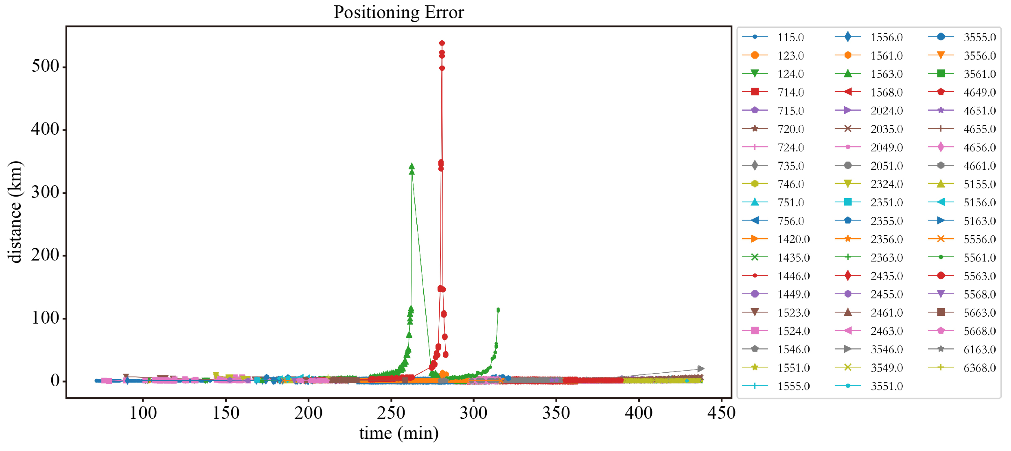
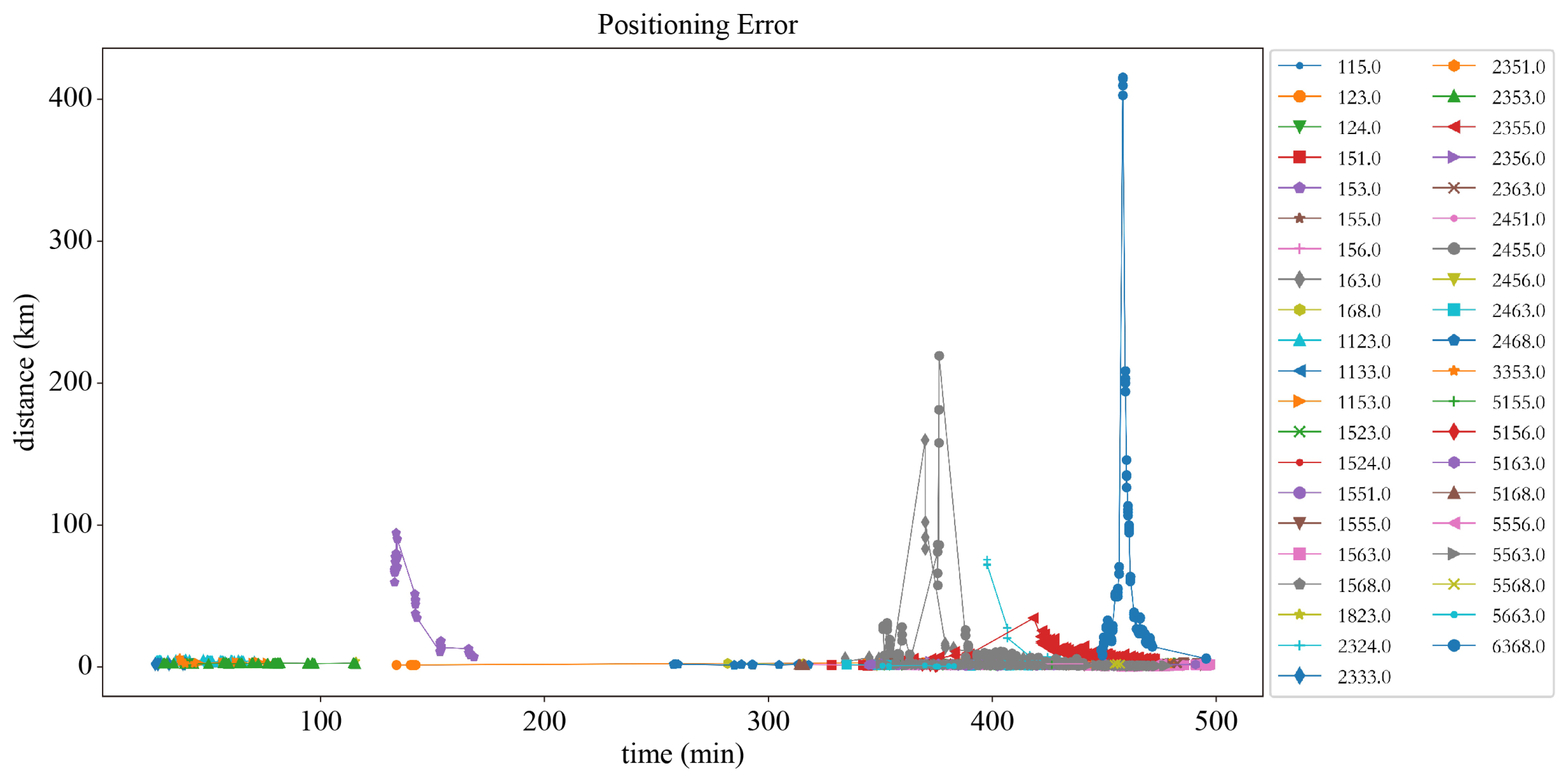
Figure 4 displays the positioning error resulting from direct interpolation calculations without star selection. Notably, combinations 55–63, 15–63, and 55–61 exhibit sharp increases in positioning error at certain moments, with maximum errors exceeding 500 km, manifesting as three distinct spikes in Figure 4. As described in the positioning accuracy model, this phenomenon occurs because the elevation angles of the two stars change over time. As the two circles approach tangency, the resulting position error becomes significantly larger.
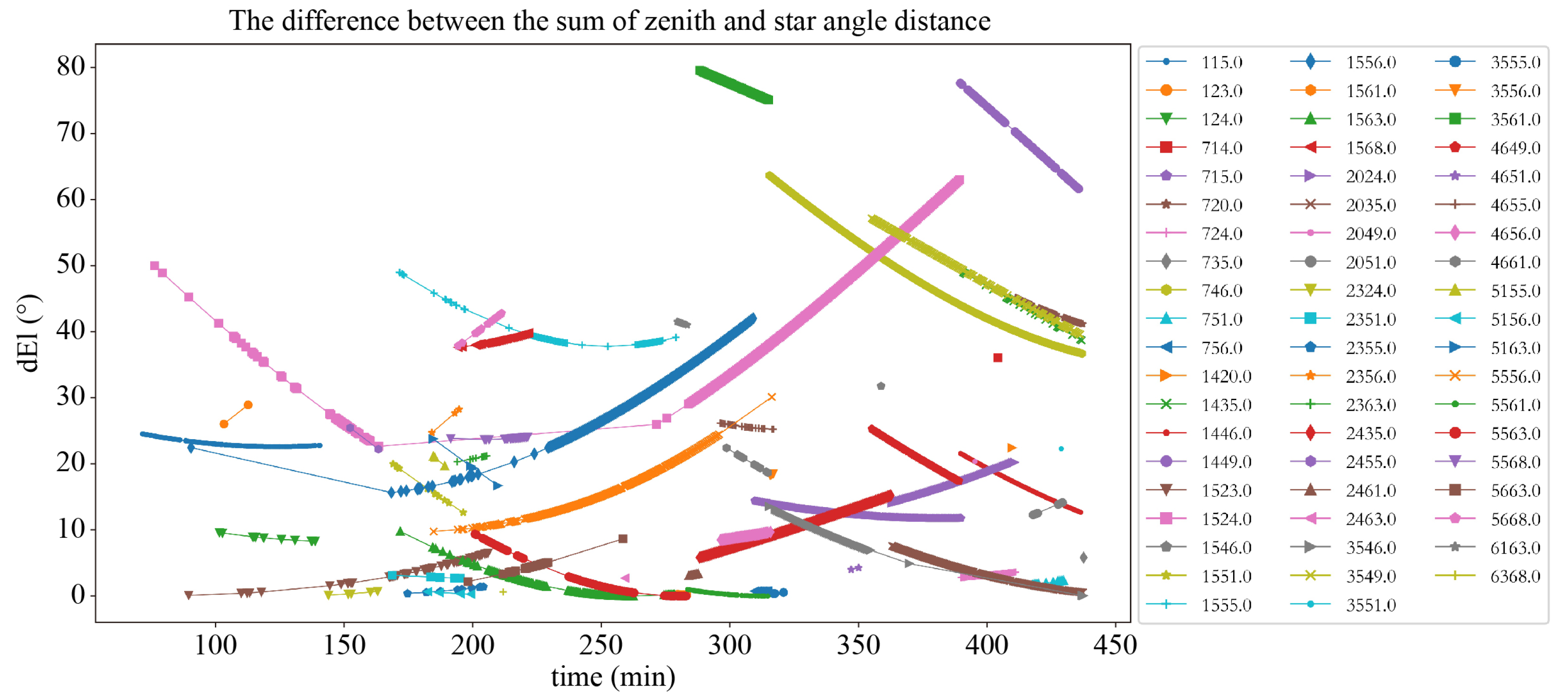
Figure 5 illustrates the differences between the star angular distances and the zenith angles of the two stars. It is evident that the combinations 55–63, 15–63, and 55–61 exhibit difference values approaching zero between 250 and 320 min. This indicates that the two circles are nearly tangential during this period, resulting in an increase in positioning error. Figure 6 further emphasizes the importance of selecting appropriate two-star combinations in practical applications, highlighting the necessity of avoiding scenarios where the two circles are tangent to each other.
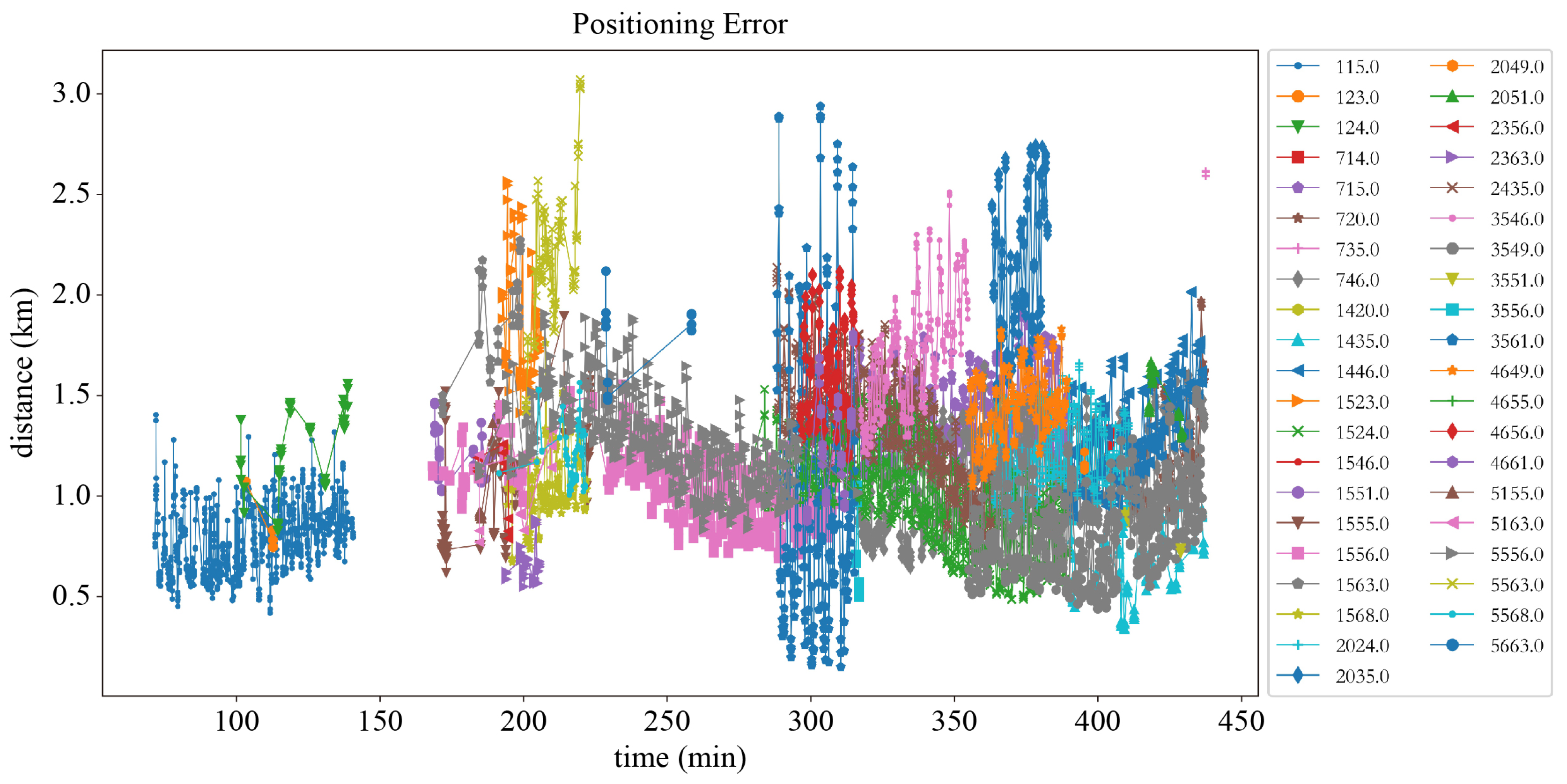
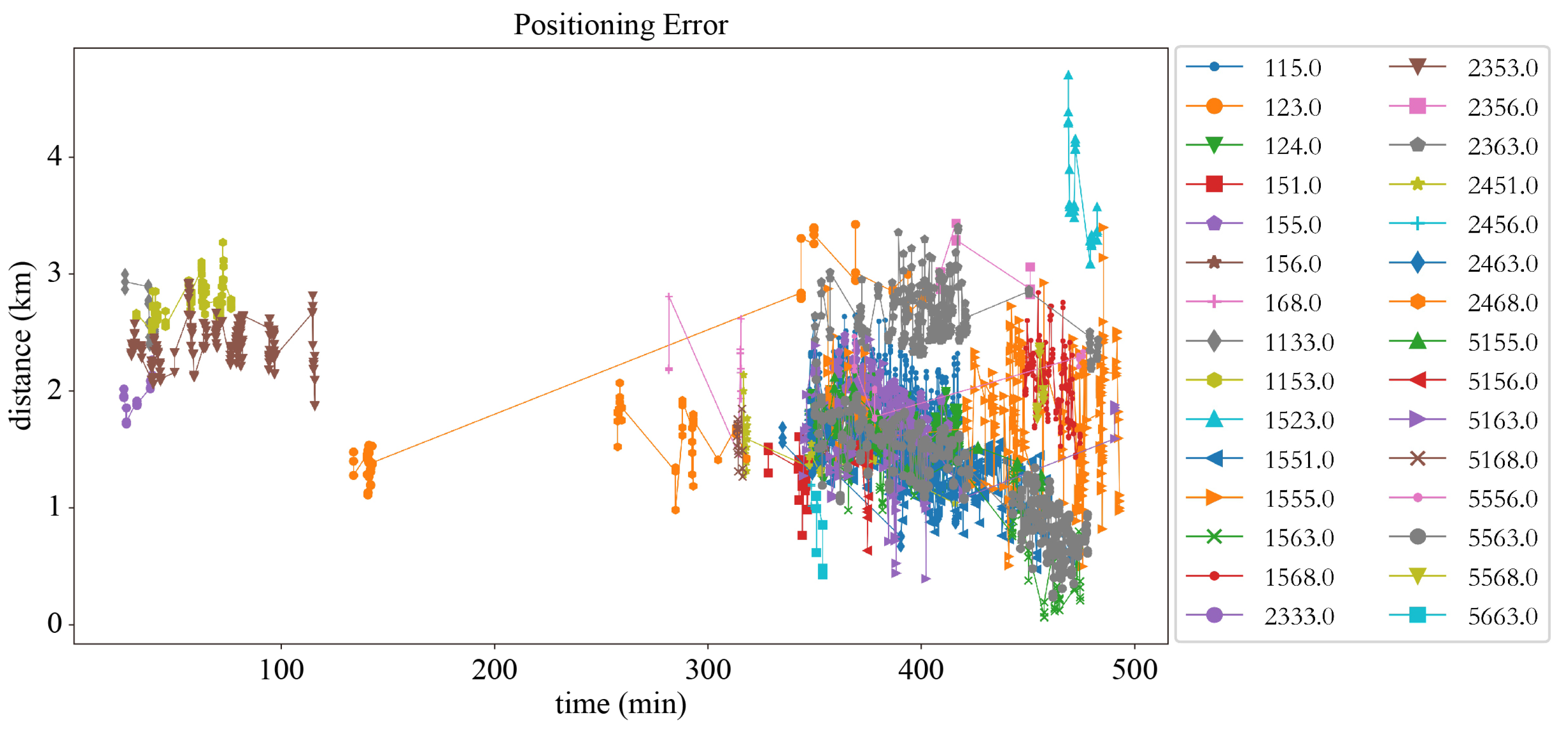
Using our proposed star selection strategy and filtering the two-star combinations, Figure 6 presents the resulting positioning errors. The maximum positioning error reaches 3071 m, while the minimum is as low as 152 m. In contrast to Figure 4, Figure 6 effectively excludes combinations that result in excessively high positioning errors. Notably, the combinations of stars 55–63 and 15–63 remain unfiltered, indicating that the positional relationship between the two circles for the same combination changes over time. It is only when they approach tangency that the elevation angle error can significantly impact positioning accuracy.
It is well known that different atmospheric conditions, such as cloudy and clear skies, result in varying light scattering and reflection properties, which can affect the star sensor’s ability to track stars. To demonstrate that our method is applicable under different weather conditions, we conducted a follow-up measurement on 11 May 2024 under overcast conditions with thicker cloud cover. All experimental setups were identical to those used on 3 May, with the only differences being the weather and test duration.
Figure 7 also shows the positioning errors generated by direct interpolation calculations without star selection. Compared to the 59 star pair combinations in Figure 4, Figure 7 only includes 41 star pair combinations. Notably, between 100 and 300 min, there are almost no valid star combinations. This illustrates that the performance of our star sensor is significantly affected by weather conditions, as the absence of star observations prevents the formation of valid star pairs for positioning. Furthermore, as with Figure 4, in the case of no star pair selection, there are individual data points where the positioning error exceeds 400 km.
Figure 8 presents the positioning errors after star pair selection using the method proposed in this paper. It can be observed that the maximum positioning error is 4700 m, and the minimum positioning error is 62 m. Compared to Figure 7, the maximum positioning error is reduced by a factor of 100, demonstrating that the method proposed here is robust for positioning under various weather conditions. Additionally, when compared to Figure 6, the maximum positioning error is increased. We hypothesize that this is due to changes in atmospheric refraction caused by weather conditions, which led to increased measurement errors in the elevation angles in the n-system. To summarize, our star selection strategy is very effective and essentially unaffected by weather and other environmental factors due to the fact that the star selection strategy is primarily based on the relative positional relationships of the stars, while environmental factors do not affect the relative positions.

5. Discussion

Directly solving Equation (6) typically requires a computational time of 0.7 to 1 s. In contrast, the dual-star positioning approach introduced in this study significantly reduces the computation time to approximately 50–80 microseconds, achieving a remarkable improvement in efficiency. This advantage makes our method well-suited for real-time processing in maritime observation scenarios. The analytical solution relies only on straightforward calculations, resulting in a much lower computational complexity compared to the direct equation-solving approach. Compared with optimization methods such as GA, the computation of the proposed method does not require iteration, and the analytical solution is more concise. In addition, the other methods such as GA for solving the two-star localization solve the positioning equations, and there is no corresponding solution strategy for the error caused by the elevation angle. The proposed star selection strategy can be applied to methods such as GA to select navigation stars before computation to ensure the reliability of the results.
Due to the limitations of experimental conditions, the static observations in this study were conducted on a rooftop without any movement of the platform. The primary difference between vessel motion at sea and the observations conducted in this study lies in the variation in the vessel’s attitude. However, this attitude information is provided by the INS and is independent of the star sensor. The dual-star positioning process remains identical for both observation scenarios.
In practical applications involving vessel motion, the influence of motion on positioning accuracy can be analyzed through Equation (9). First, star sensors can observe stars only during stable sailing conditions, where measurement accuracy is determined by the precision of the star sensor itself. Second, the installation error matrix is generally fixed and is established through calibration experiments conducted prior to the voyage. Lastly, the vessel’s attitude, provided by the INS, affects the accuracy of the altitude angle in the navigation frame, which is also influenced by the INS precision. In summary, during maritime observations, the positioning accuracy is affected by the star sensor measurement precision, the accuracy of the INS, and the correctness of the installation error calibration.
Since the proposed method requires only the measurement information from the INS and the star sensor for computation, both of which are autonomous navigation sensors that do not need to interact with external information. Therefore, regardless of the ocean environment, the proposed method can perform positioning with complete input information. However, in practical applications, the dual-star positioning model proposed is also affected by environmental factors. For instance, reflections and scattering can significantly impact the measurements of the star sensor, while harsh sea conditions may degrade the measurement accuracy of the INS. Positioning errors can be minimized by selecting star sensors and INS with higher accuracy. In other words, the proposed method has no limitation on the environment, and the instrument accuracy directly determines the positioning accuracy.
This paper primarily discusses the accuracy of dual-star positioning, which can be easily extended to multi-star observations. While dual-star positioning may result in two possible locations, multi-star observations yield a unique position where the vessel is likely to be. It is important to highlight that multi-star observations involve multiple altitude angle interpolation calculations. Each pair of stars contributes to a position computation, and the common solution across all pairs determines the vessel’s exact location.

6. Conclusions

This paper analyzes the positioning principles and algorithms of shipborne small field-of-view star sensors based on the two-star observation method. We elucidate the relationship between different coordinate systems and provide analytical solutions to the positioning equations. Aiming at the influence of elevation error on vessel positioning accuracy, a positioning accuracy model is established, and a generalized star selection strategy is given. The results of simulations and ground experiments show that the analytical solution of the positioning equations is simple to compute and real-time, and the implementation of the star selection strategy can effectively remove the great influence of elevation angle on positioning accuracy at a specific location. This star selection strategy can improve celestial navigation, which is applicable to different methods and easy to operate in practical applications. The proposed method is suitable for a variety of marine environments and provides valuable insights into the utilization of small-field-of-view star sensors for vessel navigation and positioning.

Author Contributions

Conceptualization, Y.W. and T.H.; Methodology, Y.W., C.Z., G.L. and Q.L.; Software, C.Z., G.L. and Q.L.; Validation, C.Z., T.H., G.L. and Q.L.; Formal analysis, Q.L.; Investigation, T.H. and Q.L.; Data curation, Y.W. and C.Z.; Writing—original draft, Y.W.; Writing—review & editing, C.Z., T.H., G.L. and Q.L.; Visualization, G.L.; Supervision, T.H.; Project administration, T.H.; Funding acquisition, T.H. All authors have read and agreed to the published version of the manuscript.

Funding

This research received no external funding.

Institutional Review Board Statement

Not applicable.

Informed Consent Statement

Not applicable.

Data Availability Statement

The data presented in this study are contained within this article.

Conflicts of Interest

The authors declare no conflicts of interest.

References

  1. Howell, S.P. Practical Celestial Navigation; Rowman & Littlefield: Lanham, MD, USA, 2023. [Google Scholar]
  2. Critchley-Marrows, J.J.; Mortari, D. A Return to the Sextant—Maritime Navigation Using Celestial Bodies and the Horizon. Sensors 2023, 23, 4869. [Google Scholar] [CrossRef] [PubMed]
  3. Wang, Q.; Zhang, M. Inertial navigation system gyroscopic on-line calibration assisted by marine star sensor based on forgetting factor selection of a Sage-Husa filter. J. Mar. Eng. Technol. 2022, 21, 1–8. [Google Scholar] [CrossRef]
  4. Rad, A.M.; Nobari, J.H.; Nikkhah, A.A. Optimal attitude and position determination by integration of INS, star tracker, and horizon sensor. IEEE Aerosp. Electron. Syst. Mag. 2014, 29, 20–33. [Google Scholar] [CrossRef]
  5. Zheng, X.; Huang, Y.; Mao, X.; He, F.; Ye, Z. Research status and key technologies of all-day star sensor. In Journal of Physics: Conference Series; IOP Publishing: Bristol, UK, 2020; Volume 1510, p. 012027. [Google Scholar]
  6. Han, J.; Wang, C.; Li, B. High accuracy method of positioning based on multi-star-sensor. In Proceedings of the 2016 Seventh International Conference on Intelligent Control and Information Processing (ICICIP), Siem Reap, Cambodia, 1–4 December 2016; IEEE: Piscataway, NJ, USA, 2016; pp. 236–242. [Google Scholar]
  7. Nguyen, V.S.; Im, N. Development of computer program for solving astronomical ship position based on circle of equal altitude equation and SVD-least square algorithm. J. Navig. Port Res. 2014, 38, 89–96. [Google Scholar] [CrossRef]
  8. Pierros, F. Stand-alone celestial navigation positioning method. J. Navig. 2018, 71, 1344–1362. [Google Scholar] [CrossRef]
  9. Van Allen, J.A. An analytical solution of the two star sight problem of celestial navigation. Navigation 1981, 28, 40–43. [Google Scholar] [CrossRef]
  10. Tsai, K.C.; Tseng, W.K.; Chen, C.L.; Sun, Y.J. A Novel Analytical Solution Method for Celestial Positioning. J. Mar. Sci. Eng. 2022, 10, 771. [Google Scholar] [CrossRef]
  11. Zhao, X.; Jia, H.; Wu, J.; Ma, Z. Research of Computer Assisted Astronomical Positioning Algorithm. In Proceedings of the 2009 2nd International Congress on Image and Signal Processing, Tianjin, China, 17–19 October 2009; IEEE: Piscataway, NJ, USA, 2009; pp. 1–4. [Google Scholar]
  12. Chen, C.L.; Hsu, T.P.; Chang, J.R. A novel approach to determine the astronomical vessel position. J. Mar. Sci. Technol. 2003, 11, 6. [Google Scholar] [CrossRef]
  13. Nguyen, V.S.; Im, N.K.; Dao, Q.D. Azimuth method for ship position in celestial navigation. Int. J. E-Navig. Marit. Econ. 2017, 7, 55–62. [Google Scholar] [CrossRef]
  14. Nguyen Thai Duong, L.T.N. Determining Ship’s Position by the Celestial Altitude Difference Using the Least Squares Method. J. Hunan Univ. Nat. Sci. 2021, 48, 199–207. [Google Scholar]
  15. Tsou, M.C. Celestial navigation fix based on particle swarm optimization. Pol. Marit. Res. 2015, 22, 20–27. [Google Scholar] [CrossRef]
  16. Li, H.; Lu, G.; Wang, W.; Wang, A.G. An Optimization Model and Genetic Algorithm Solution for Automated Celestial Navigation of Ships. Appl. Mech. Mater. 2014, 548, 1277–1281. [Google Scholar] [CrossRef]
  17. Tsou, M.C. Genetic algorithm for solving celestial navigation fix problems. Pol. Marit. Res. 2012, 19, 53–59. [Google Scholar] [CrossRef]
  18. Li, C.h.; Chen, Z.l.; Liu, X.j.; Chen, B.; Zheng, Y.; Tong, S.; Wang, R.P. Adaptively robust filtering algorithm for maritime celestial navigation. J. Navig. 2022, 75, 200–212. [Google Scholar] [CrossRef]
  19. Khan, A.H.; Cao, X.; Li, S.; Katsikis, V.N.; Liao, L. BAS-ADAM: An ADAM based approach to improve the performance of beetle antennae search optimizer. IEEE/CAA J. Autom. Sin. 2020, 7, 461–471. [Google Scholar] [CrossRef]
  20. Bate, R.R.; Mueller, D.D.; White, J.E.; Saylor, W.W. Fundamentals of Astrodynamics; Courier Dover Publications: Mineola, NY, USA, 2020. [Google Scholar]
  21. Yang, S.; Feng, W.; Wang, S.; Li, J. A SINS/CNS integrated navigation scheme with improved mathematical horizon reference. Measurement 2022, 195, 111028. [Google Scholar] [CrossRef]
  22. Zheng, Z.; Han, S.; Zheng, K. An eight-position self-calibration method for a dual-axis rotational inertial navigation system. Sens. Actuators A Phys. 2015, 232, 39–48. [Google Scholar] [CrossRef]
  23. Lu, J.; Lei, C.; Liang, S.; Yang, Y. An all-parameter system-level calibration for stellar-inertial navigation system on ground. IEEE Trans. Instrum. Meas. 2017, 66, 2065–2073. [Google Scholar] [CrossRef]
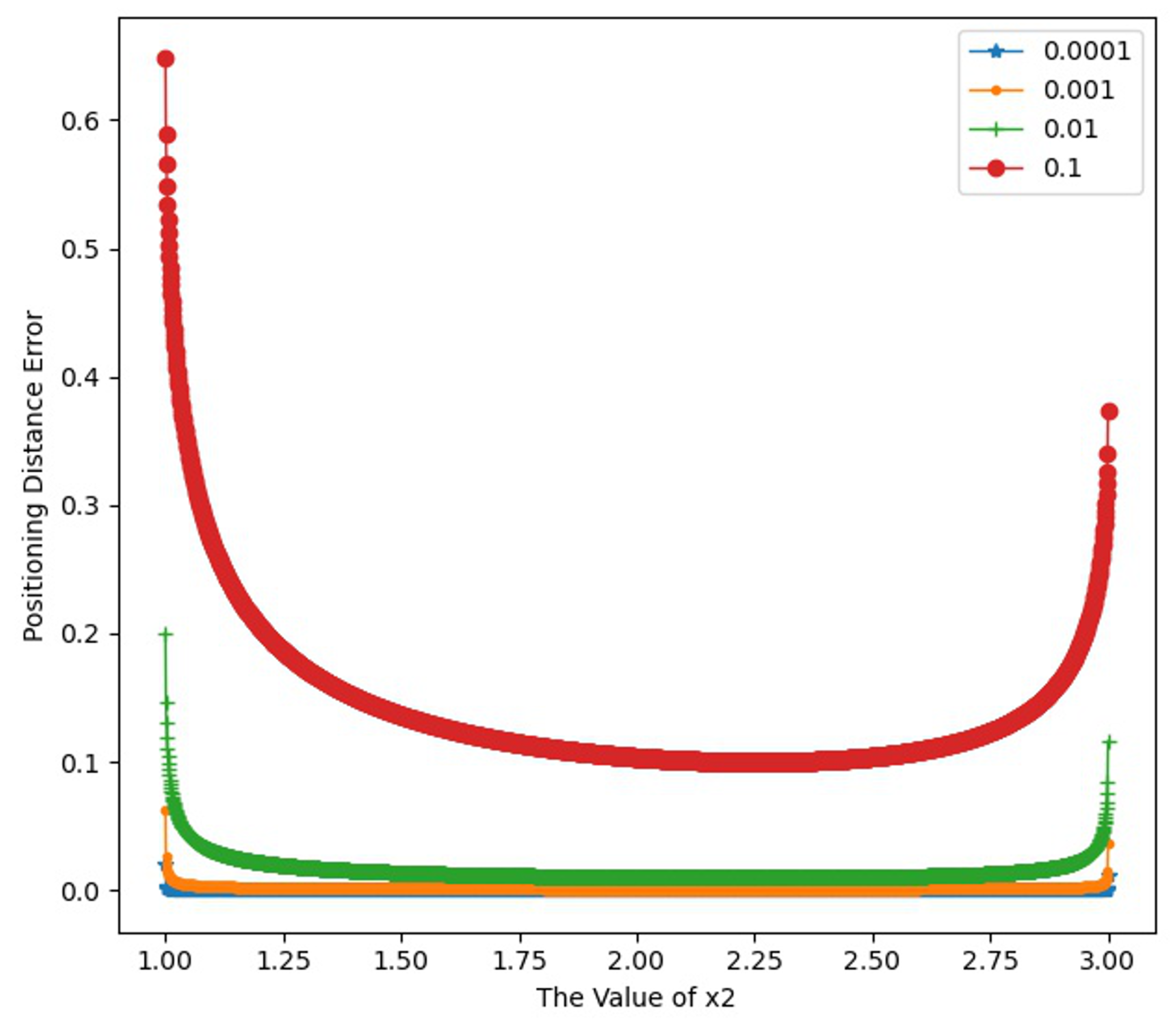
Figure 1. Radius error simulation.
Jmse 12 02347 g001
Figure 2. Positioning error simulation results.
Jmse 12 02347 g002
Figure 3. Positioning error simulation results.
Jmse 12 02347 g003
Figure 4. Positioning error results without star selection on 3 May 2024.
Jmse 12 02347 g004
Figure 5. The difference between the sum of the zenith and star angle distance.
Jmse 12 02347 g005
Figure 6. Positioning error results with star selection on 3 May 2024.
Jmse 12 02347 g006
Figure 7. Positioning error results without star selection on 11 May 2024.
Jmse 12 02347 g007
Figure 8. Positioning error results with star selection on 11 May 2024.
Jmse 12 02347 g008
Table 1. Navigation star details.
Observation GHA: 339.534°
Location: Longitude 91.532° W; Latitude 41.662° N
StarRight Ascension (°)Declination (°)Elevation Angle (°)
Arcturus−125.91519.31736.704
Altair−42.1568.79954.382
Antares−92.581−26.37668.045
Vega−60.52038.75923.731
Table 2. Comparison of results with other methods of two-star positioning.
James A. Van Allen Method (°)King-Cheng Tsai Method (°)Our Method (°)
Star CombinationPosition 1Position 2Position 1Position 2Position 1Position 2
Arcturus—Altair41.661−2.14841.6615−2.148441.66149−2.14840
−91.532−95.605−91.5321−95.6052−91.53208−95.60520
Arcturus—Antares41.6620.13641.66210.136141.662080.13607
−91.532−157.841−91.5325−157.8410−91.53248−157.84100
Arcturus—Vega41.66129.33441.661329.334041.6612829.33396
−91.532−86.95−91.5319−86.9504−91.53194−86.95039
Antares—Vega41.66221.00941.662121.009441.6620721.00941
−91.532−42.186−91.5320−42.1856−91.53200−42.18559
Altair—Vega41.66262.29541.661762.295241.6616962.29522
−91.532−55.55−91.5320−55.5504−91.53197−55.55036
Altair—Antares41.662−37.14341.6621−37.143241.66207−37.14315
−91.532−11.087−91.5318−11.0869−91.53176−11.08690
Table 3. Latitude and errors of the three positioning methods.
Star CombinationPositionJames A. Van Allen Method (°)King-Cheng Tsai Method (°)Our Method (°)Ours–James (″)Ours-Tsai (″)
Arcturus—AltairPosition 141.66141.661541.661491.7712−0.0288
Position 2−2.148−2.1484−2.14840−1.42560.0144
Arcturus—AntaresPosition 141.66241.662141.662080.2772−0.0228
Position 20.1360.13610.136070.24120.0012
Arcturus—VegaPosition 141.66141.661341.661280.9972−0.0228
Position 229.33429.334029.33396−0.144−0.024
Antares—VegaPosition 141.66241.662141.662070.2520.012
Position 221.00921.009421.009411.4580.018
Altair—VegaPosition 141.66241.661741.66169−1.10160.0384
Position 262.29562.295262.295220.7776−0.0024
Altair—AntaresPosition 141.66241.662141.662070.24120.0012
Position 2−37.143−37.1432−37.14315−0.53280.0072
Table 4. Longitude and errors of the three positioning methods.
Star CombinationPositionJames A. Van Allen Method (°)King-Cheng Tsai Method (°)Our Method (°)Ours–James (″)Ours-Tsai (″)
Arcturus—AltairPosition 1−91.532−91.5321−91.53208−0.29520.0048
Position 2−95.605−95.6052−95.60520−0.7020.018
Arcturus—AntaresPosition 1−91.532−91.5325−91.53248−1.7280.012
Position 2−157.841−157.8410−157.84100−0.0072−0.0072
Arcturus—VegaPosition 1−91.532−91.5319−91.531940.2268−0.0132
Position 2−86.95−86.9504−86.95039−1.41840.0216
Antares—VegaPosition 1−91.532−91.5320−91.532000.00360.0036
Position 2−42.186−42.1856−42.185591.46520.0252
Altair—VegaPosition 1−91.532−91.5320−91.531970.1116−0.0084
Position 2−55.55−55.5504−55.55036−1.2996−0.0396
Altair—AntaresPosition 1−91.532−91.5318−91.531760.8640.024
Position 2−11.087−11.0869−11.086900.3492−0.0108
Table 5. The location relationship for the positioning circles in two-star combinations.
Star CombinationTwo-Circle PositionStar Angular Distance (°)The Sum of the Zenith (°)The Difference of the Zenith (°)Difference (°)
Arcturus—AltairExternal74.61788.443/13.826
Arcturus—AntareInternal53.784/28.03725.747
Arcturus—VegaExternal56.51859.641/3.123
Altair—AntaresInternal57.519/11.75245.767
Altair—VegaInternal33.690/28.8024.888
Antares—VegaInternal67.115/40.55426.561
Disclaimer/Publisher’s Note: The statements, opinions and data contained in all publications are solely those of the individual author(s) and contributor(s) and not of MDPI and/or the editor(s). MDPI and/or the editor(s) disclaim responsibility for any injury to people or property resulting from any ideas, methods, instructions or products referred to in the content.