Article

An Early-Stage Structural Design of a Semi-Submersible Platform for Floating Offshore Wind Turbines in Chilean Waters

by
Yordan Gallardo
,
Gonzalo Tampier
,
Víctor Palma
,
Cristian Cifuentes
,
José Miguel Ahumada
,
Claudio Troncoso
and
Michael Y. Mendoza
*
Institute of Naval Architecture and Ocean Engineering, Universidad Austral de Chile, Valdivia 5090000, Los Rios XIV, Chile
*
Author to whom correspondence should be addressed.
J. Mar. Sci. Eng. 2024, 12(11), 1951; https://doi.org/10.3390/jmse12111951
Submission received: 6 September 2024 / Revised: 30 September 2024 / Accepted: 9 October 2024 / Published: 31 October 2024
(This article belongs to the Section Coastal Engineering)

Abstract

:
To advance offshore wind energy technologies in South America, this study addresses the early-stage design challenges of a floating support structure for a 5 MW wind turbine. The aim is to develop a robust and efficient floating structure capable of withstanding the diverse forces imposed by the Valdivian environment. Utilizing SolidWorks, a 3D model based on a comprehensive review of semi-submersible structures with three columns is proposed. The structural model is subjected to a rigorous evaluation using the finite element method, with which linear static and buckling analyses are performed in compliance with the Det Norske Veritas (DNV) classification society. The proposed tri-floater platform design shows a 30% weight reduction when compared with other proposed models. The finite element analysis includes an extreme condition of 13 m waves that suggests the adequate performance of the proposed platform in Chilean waters, and offers a conceptual preliminary step for floating support structure designs in Chile.

1. Introduction

Generating clean energy through offshore wind turbines is an excellent option, albeit with a higher economic investment than onshore wind turbines [1]. The advantage of offshore turbines lies in the higher wind speed, strength, and consistency at sea, unobstructed by barriers or obstacles that may alter the wind’s trajectory. This translates to a more consistent and uniform energy generation. While offshore turbines’ capacity reached 56 GW worldwide in 2021, mainly in Europe and China [2], there is still a significant need to establish such plants in South America [3]. In Chile, despite the abundant offshore winds, the bathymetric, operational, and extreme conditions present significant challenges for implementing this technology, which has a high potential in the central and southern regions (33° S to 43° S). Due to the bathymetry of these regions, floating wind platforms offer a better overall solution than bottom-fixed alternatives [4].
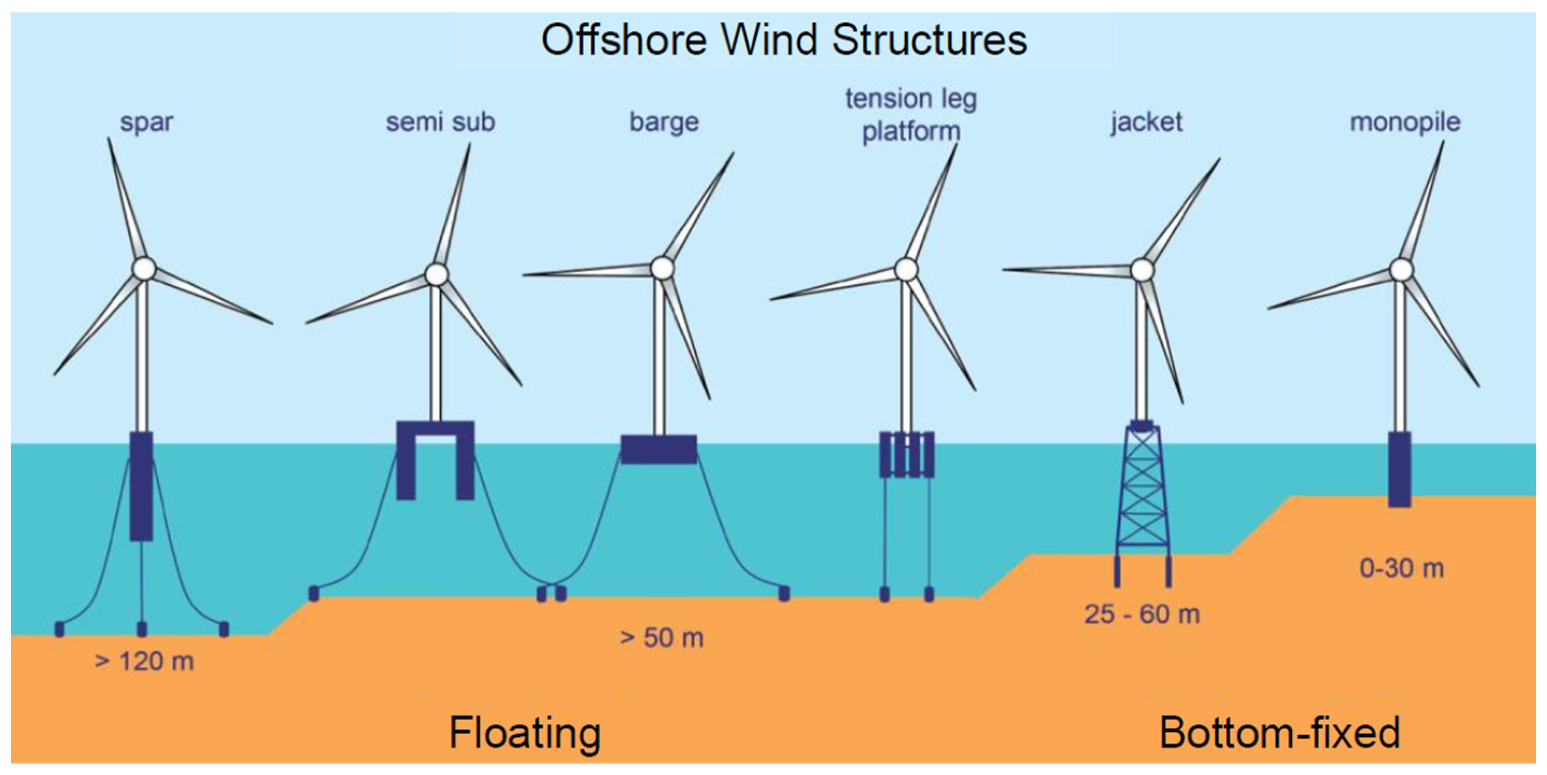
There are four main types of floating wind platforms: tension leg, spar, barge, and semi-submersible. Their main differences, advantages, and specific requirements have been discussed extensively, which have implications for their recommended installation depths and different requirements for their construction and installation. As of today, semi-submersible platforms are considered the most competitive option for deep waters, as they can be optimized and are compatible with a catenary mooring system [5]. Currently, the catenary mooring system is typically used in Chile’s fish farming centers, making semi-submersible platforms attractive for future implementation.
Faraggiana et al. [5] conducted a comparative analysis to evaluate the methods and strategies used in the conceptual design of semi-submersible platforms for Floating Offshore Wind Turbines (FOWT). The study revealed that semi-submersible platforms are the most promising option for greater water depths and offer the highest potential for optimization. For water depths less than 60 m, bottom-fixed platforms are considered the optimal solution. The study highlighted the importance of cost reduction, which can be achieved by minimizing the size and quantity of the steel used in construction. The tri-floater-type platform, featuring three floaters, was noted for its cost-effectiveness compared to designs incorporating more floaters. The authors also discussed the stability of semi-submersible platforms, which are stabilized through buoyancy by a large waterplane area inertia, lifting the metacenter above the center of gravity. In contrast, tension-leg platform (TLP) types are stabilized through vertical taut moorings, and spar-type platforms use a heavy ballast placed as low as possible to increase the metacentric height. The semi-submersible platform is a concept which requires a detailed optimization process due to its high cost. However, the three substructure principles described in their paper are often combined in hybrid solutions. Figure 1 shows a classification diagram that aids in understanding and distinguishing between the different platform concepts.
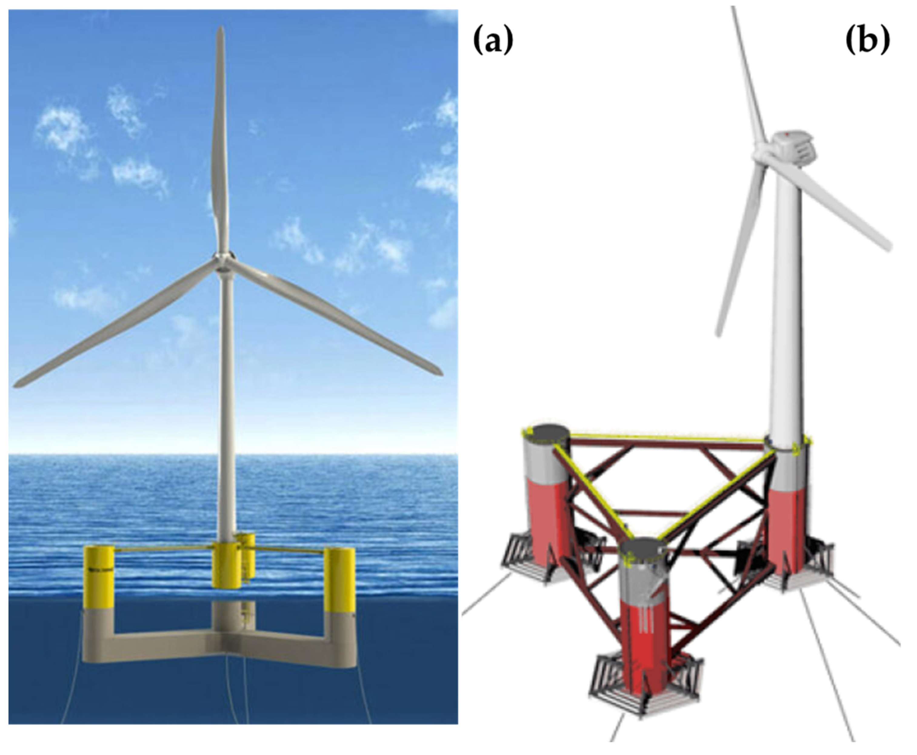
In recent years, several floating wind platforms have been developed and tested, such as WindFloat [6], VolturnUS [7], and Tri-Floater [8,9] (semi-submersibles); IDEOL (barge type); HyWind (spar type); and Float4Wind (TLP).
Lefebvre et al. [10] conducted a comprehensive study assessing seven semi-submersible platform designs. The evaluation criteria included the cost, restoration moment, and construction feasibility. They used the National Renewable Energy Laboratory (NREL) 5 MW turbine design and the Dogger Bank site in the North Sea (UK) as the input. The researchers ultimately identified the most appropriate design and subjected it to rigorous analyses, including structural resistance, mechanical vibration, dynamic response (RAO), and stability. Notably, the design considerations were inspired by the structural requirements outlined by the oil and gas industry’s standards for offshore platforms. The study established specific criteria for acceptance as listed below:
  • For the static analysis, a minimum safety factor of 1.6 was used since, at the time of publication, there were no specialized codes for calculating offshore wind platforms.
  • The maximum intact pitch angle for stability was 10°, and for damaged conditions it was 20°.
  • The maximum offset for the mooring system was 10 m.
  • The structure dynamics include calculations with the RAOs, including the critical damping and undamped condition for the worst-case scenario.
The authors concluded that the pitch motion is the critical design driver for a wind turbine and the stability of its support structure. Since the study was based on simulation results, they recommended that a scaled model of the structure be tested to validate and understand the hydrodynamic behavior of the system. Kim et al. [11] reported a comparison of different numerical models of the IEA 15 MW/UMaine floater for an offshore site in South Brittany, France. They focused the work on comparing the results of the different numerical approaches, and concluded that the FOWT model was not well designed for the extreme waves at the South Brittany site [11]. The WindFloat Atlantic project [6] is the first pre-commercial wind farm with a semi-submersible technology. It is located off the coast of Viana do Castelo, Portugal, and was launched in 2020. The project aims to provide clean energy to the Portuguese electrical grid and has a calculated lifespan of 25 years. The wind farm was installed 18 km from the coast at a depth of around 100 m. In comparison to the Hiperwind project [11], the main difference in the WindFloat Atlantic design is the location of the wind generator. It is positioned on one of the floaters, which reduces the number of additional reinforcements needed to connect the tower to the floaters. Another configuration corresponds to the GustoMSC Tri-Floater [9,12], with a structural design of a semi-submersible with three floaters. Unlike the previously reviewed models that use a circular design, this platform employs a regular hexagon as the cross section of the floaters, which reduces the construction time and cost by eliminating the need to manufacture large cylindrical columns. This design is also dimensioned for the 5 MW NREL reference wind turbine and located in a fictive offshore site at a 100 m water depth. These aspects simulate the interaction between the wind loads on the rotor and the motions of the floating structure. They concluded, from the very conceptual stage of the design, that the tri-floater design met the design requirements regarding global motions, accelerations, and mooring loads [9]. Figure 2 illustrates some of the semi-submersible configurations, such as VolturnUS and WindFloat Atlantic.
This work focusses only on the conceptual and preliminary stage of the structural design process for a semi-submersible platform for use by the potential Chilean offshore wind industry. The design of structures for offshore wind turbines is a relatively new field. Previous reports in the literature have addressed the early design process in locations such as the UK [10], France [11], and other European locations [6], but there is a lack of information regarding South America and particularly Chile, which has a high potential for utilizing offshore renewable energy [3,15].
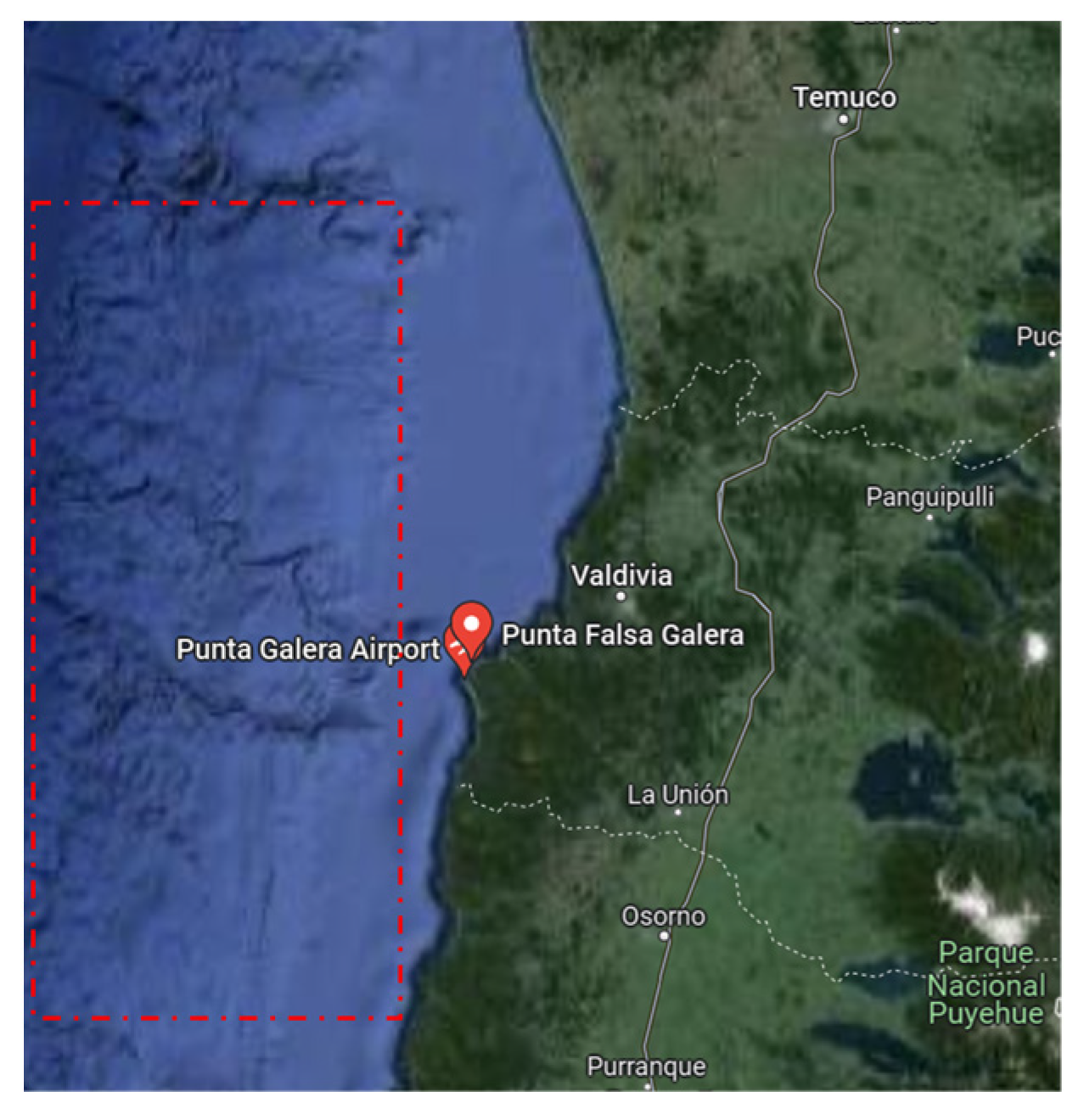
The research described in this paper analyzes different structures from the literature in terms of the size/shape of floaters and the space between them. It also analyzes the substructures that connect the floaters and tower to propose an early-stage design for a semi-submersible structure for Chilean waters. The structural design follows the guidelines of the DNV classification society for floating wind turbine structures [16], environmental conditions and environmental loads [17]. In addition, the sea and wind conditions used for the design process correspond to an area near to the coast of Valdivia, a city in the Los Rios region of Chile, as indicated in Figure 3 [18,19].

2. Methods and Materials

2.1. Offshore Wind Turbine Model

The National Renewable Energy Laboratory (NREL, USA) has a detailed description of a 5 MW offshore wind turbine designed to be used as a model for the early-stage design of support structures. This offshore wind turbine model has been used as a reference in several studies [10,20,21]. Therefore, this model is also used as a reference in this study due to the open access and detailed information. The main characteristics of the offshore wind turbine and the tower are presented in Table 1 [20].

2.2. Proposed Offshore Semi-Submersible Platform

The platform’s primary dimensional specifications are based on the research conducted by Lefebvre et al. [10], and the main data are presented in Table 2. This is a tri-floater design with an original cylindrical shape, but it is modified to have floaters with a hexagonal shape for construction simplicity, as demonstrated by the GustoMSC Tri-Floater [12,22] and WindFloat F [23]. For the wind tower positioning, the concept adopted is from the WindFloat Atlantic project. The wind turbine is located on one of the floaters to optimize the quantity of reinforcements used in the support structure. As can be inferred, the proposed offshore semi-submersible platform is a combinatorial approach of previous models. Figure 4 shows the proposed semi-submersible platform. There is an important additional port installation advantage when using the selected design, which is the reduction in the lifting capacity needed for the installation crane due to the reduction in the horizontal distance from the quayside to the center of the wind turbine.

2.3. Chilean Environmental Conditions and Platform Material

The sea and wind conditions correspond to an area near the coast of Valdivia city in the Los Rios region of Chile [18,19]. The Beaufort wind force scale is used to relate the wind speed to the observed conditions at sea. Table 3 shows the Chilean environmental conditions. The selected material for construction is S275 structural steel, and the assumption of a slightly higher density of the steel is made to account for the plates’ welding and bolting. Table 4 illustrates the main properties of the S275 steel.

2.4. Structural Calculations and Finite Element Analysis Software

The structural calculations follow the DNV standard and recommended practices of DNVGL-ST-0119 [16] and DNVGL-RP-C205 [17]. In shipbuilding, the term scantling refers to the dimensions and strength of the structural elements or framing. Thus, the scantling is necessary for the structural calculations for the tri-floater support platform. The process follows the determination of the pressure design, minimum thickness, thickness by section, and minimum modulus.

2.4.1. Pressure Design

The pressure design for the plating and bulkheads should be determined first to identify the structural elements, such as the plating and its respective reinforcements.

Plate Pressure Design

The dynamic and static pressure must be considered on the platform structure, and they are directly related to the draught (i.e., the vertical distance from the underneath side of the keel to the waterline). The dynamic pressure is at its highest value when the structure reaches the wave crest. This is the most unfavorable scenario, so it is considered critical to the pressure design. Therefore, DNVGL-ST-0119 defines the plate pressure as follows:
P D = P S × Y f , G , Q + P e × Y f , E
where
  • Ps = static pressure;
  • YF,G,Q = permanent load factor;
  • Pe = dynamic pressure;
  • Yf,E = environmental load factor.
The static pressure is as follows:
P S = ρ × g × T E Z b 0   K N / m 2
where
  • ρ = water density;
  • g = gravity acceleration;
  • TE = maximum operational draught (m);
  • Zb = vertical distance between the baseline to the pressure measurement point.
The dynamic pressure is as follows.
When Z b T E :
P e = ρ × g D D Z b   K N / m 2
And when Z b < T E :
P e = 0.5 ρ H e k z c o s θ
where
  • DD = vertical distance from the molded baseline to the wave crest;
  • H = wave crest height.

Bulkhead Pressure Design

The DNV recommends a preliminary value of 25% for the vertical acceleration of the acceleration gravity. Similar to the plate pressure design, the pressure varies depending on the water column’s height with respect to the baseline. Therefore, the bulkhead pressure design is as follows:
P d = ρ × g × h o p × ( Y f , G , Q + a v g Y f , E )
where
  • hop = vertical distance from the load point to the maximum filling position;
  • av = vertical acceleration.

2.4.2. Thickness

According to the DNV rules, there are two expressions for the thickness determination. Equation (6), for the minimum thickness, depends on the material and type of structure (i.e., primary or secondary). However, Equation (7), for the thickness by section, depends on the material and external pressure. These equations allow for the determination of the thickness for the external plating, vertical and horizontal bulkheads, and floater covers.
t = 14.3 t o f y d
  • to = 7 mm for the primary elements and 5 mm for the secondary elements;
  • fyd = material yield strength (steel S275).
t = 15.8 k a k f S P d σ p d 1 × k p p   ( m m )
where
  • k a = correction factor for the panel aspect ratio (1.1–0.25 s/l)2
  • k f = correction factor for the perpendicular curvature of the stiffeners (1–0.5 s/rc);
  • rc = radius of curvature;
  • S = stiffener spacing (m), measured along the plating;
  • σpd1 = bending stress design;
  • kpp = fixation parameter for the plate; 1.0 for clamped edges.

2.4.3. Minimum Section Modulus

The minimum section modulus for all the stiffeners subjected to lateral pressure shall not be less than the value expressed by Equation (8). Additional details for the equations can be found in DNVGL-ST-0119.
Z m = S × l 2 × P d k m × k P s × σ p 2
where
  • l = stiffener span (m);
  • Km = bending moment factor;
  • σp2 = design bending stress;
  • Kps = fixation parameter for the stiffeners;
  • S = stiffener spacing (m), measured along the plating.

2.4.4. Finite Element Analysis Software

The structural calculations of the DNV standards are followed by a numerical approach using the commercial software SolidWorks® 2021 professional. The simulation by the software includes the material properties, constraints, and external applied loads. The external forces acting on the tri-floater platform are the thrust force generated by the wind turbine engine operation, its weight, and the wind and hydrodynamic forces of the waves and currents.

3. Results

3.1. The Environmental and Operational Forces Acting on the Platform

The external forces acting on the tri-floater platform are the thrust force, wind turbine weight, wind forces, and wave and current forces. The maximum force generated by this turbine is 800 kN, and the vertical distance from the rotor’s center to the tower base is 77.6 m. Therefore, the thrust moment is 62,080 kNm. Table 1 presents the wind turbine weight resulting in a force of 7404 kN. The wind forces on the structure are calculated according to the recommended practice by DNVGL-RP-C205. The Valdivia environmental conditions listed in Table 3 are the input values used to obtain the wind forces on the tower (see Table 5) and the wind forces on each floater (see Table 6).
The wave and current forces are hydrodynamic and viscous forces (see Table 7) resulting from pressure changes (i.e., wave action) along with fluid movement (i.e., current flow). Morison’s load formula is used, which considers a deep water regime, to simplify the equation for velocity and flow acceleration [17,24,25].

3.2. Plate Pressure Design Results

Each floater has four sections or compartments from bottom to top. Compartment 4 is 6570 mm, compartments 3 and 2 are 6490 mm, and compartment 1 at the top is 2950 mm, for a total height of 22,500 mm as illustrated in Figure 4. The plate pressure results for the compartment walls are indicated in Figure 5; compartment 1 is N/A because it is not submerged into the water.

3.3. Bulkhead Pressure Design Results

The floaters have three horizontal bulkheads to provide watertightness in case of damage. Two floater covers are also integrated into the design, with the upper cover located above the waterline and not subjected to those water forces. The lower floater cover has a larger diameter and experiences the most significant pressures, with a value of 269,738 kPa. Table 8 shows the bulkhead pressure design results.

3.4. Thickness Results

The plate thickness results are shown in Table 9 for the four floater compartments. Figure 6 shows the compartments’ wall reinforcement distribution, and the bulkheads’ thicknesses with their respective reinforcements are shown in Table 10 and Figure 7. In addition, the thickness of the lower floater cover is 36 mm and is 8 mm for the upper floater cover. Finally, the vertical bulkheads have the same thickness as the adjacent plate, whose function is to act as a double wall in a collision situation.

3.5. Minimum Section Modulus, Wind Turbine Support, and Floater Connectors Results

Following DNVGL-ST-0119, the minimum section modulus is 15 × 103 mm3 and, as mentioned before, the wind turbine tower is positioned on one of the floaters, which has a slightly different scantling for supporting the extra weight. The connecting element between the wind turbine tower and the floater is a one-meter-width ring with a thickness of 10 mm. As for the joining elements, they are responsible for the tri-floater structure integrity and they must support all the interactive forces. Based on previous models and the Norsok standard [26], the primary elements should have a diameter of 1.2 m and a thickness of 12 mm. On the other hand, for the secondary elements the diameter is 0.9 m with a thickness of 8 mm.

3.6. Finite Element Analysis Results

For the numerical approach, the same external forces, such as gravity and the pressure design conditions, are considered. However, for the simulation, an extreme value for the wave height (13 m) is used instead of the significant one used for the structure pre-sizing. This value is also used as an extreme condition by the manufacturer GustoMSC.

3.6.1. Floater Covers

On the lower floater cover, the pressure is 293.738 kPa and the maximum displacement is 6.79 mm. The safety factor is 1.39 and Figure 8 shows the stress and displacement from the FEA software. The upper floater cover is validated with a load of 1 ton/m2, the displacement is 5.38 mm, and the maximum stress is 205.36 Mpa (see Figure 9).

3.6.2. Horizontal Bulkheads

The lowest-located bulkhead in the floaters is number 3 (see Figure 4). It has the greatest pressure design of 176.062 kPa. Figure 10 shows the stress distribution, with a maximum of 120.2 MPa (safety factor of 2.23) and a deformation of 1.06 mm. Bulkhead 2 has a pressure design of 83.5 kPa, and bulkhead 1 has a pressure below 30 kPa. Table 11 shows the horizontal bulkhead values for the pressure design, maximum stress, and maximum deformation for all three different bulkhead thicknesses.

3.6.3. External Floater Plates

Considering a 13 m wave, the pressure increases to 214.854 kPa at the walls (i.e., plates) of compartment 4. The maximum stress is 230.22 MPa and the maximum deformation is 3.26 mm. Figure 11 shows the stress and displacement distribution on that structure. Table 12 presents the pressure design, stress, and deformation of the three compartment plates under the waterline.

3.6.4. Vertical Bulkheads

The pressure design is 49.431 kPa for vertical bulkhead 1, considering a 13 m wave condition. For vertical bulkhead 2, the pressure design is 103.338 kPa, and Figure 12 and Figure 13 show the stress and displacement distribution of vertical bulkheads 1 and 2, respectively.

3.6.5. Floater Joining Elements

These structural elements (see Figure 14) are exposed to a combination of forces, such as gravity, wind, hydrostatic pressure, waves, and current action. For this purpose, the structure associated with the pipe section beams will be segmented for the forces and buckling analysis. Figure 13 shows the displacement and stress distribution for the segmented structural element. The buckling factor of safety (BFS) is defined as the ratio of the buckling loads to the applied loads. BFS values of 0 < BFS ≤ 1 indicate that the applied loads exceed the estimated critical loads, and buckling is expected. On the other hand, if the BFS values are >1, it indicates that the applied loads are less than the estimated critical loads, and buckling is not expected. Figure 15 shows a buckling factor of safety of 6.63, which indicates that buckling is not expected.

3.6.6. Wind Turbine Tower Support Element on Floater

The structural element is a one-meter-width ring with a thickness of 10 mm. A stress and displacement analysis are conducted considering all the forces associated with the wind turbine’s tower operation, weight, and the wind acting on the structural element. Figure 16 shows the results, with a maximum displacement of 1.52 mm.

4. Discussion

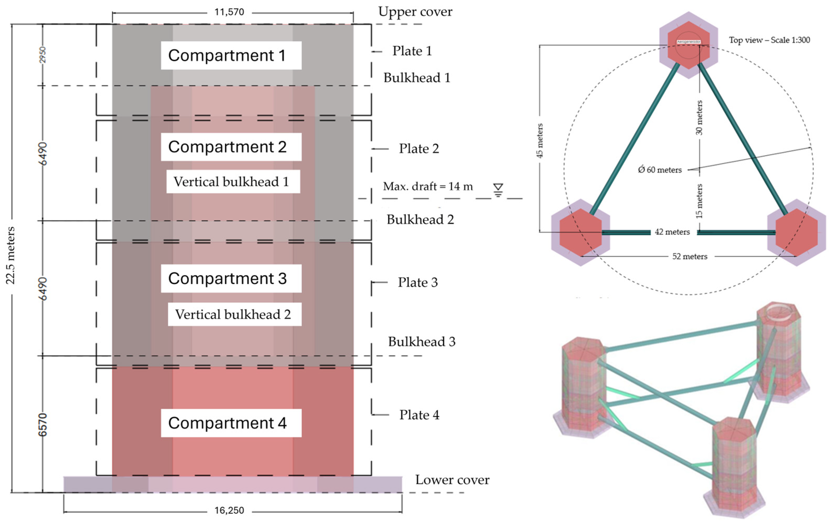
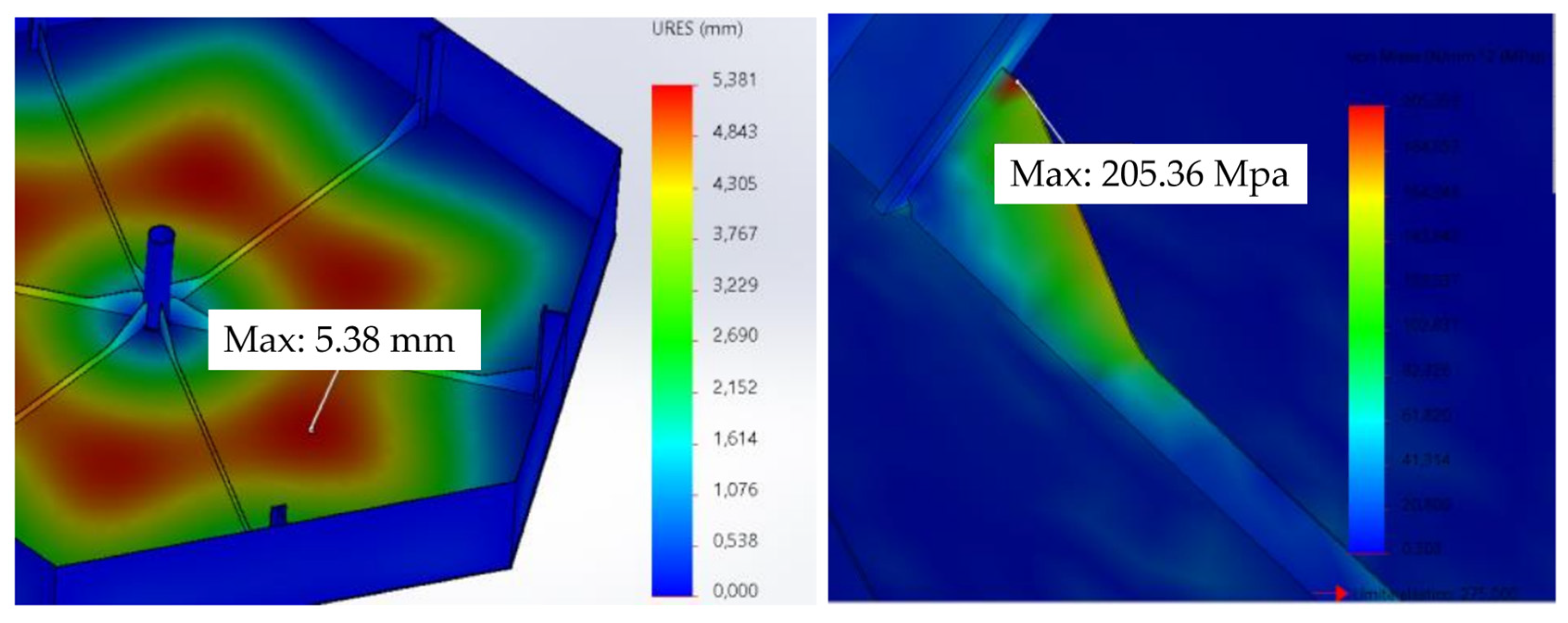
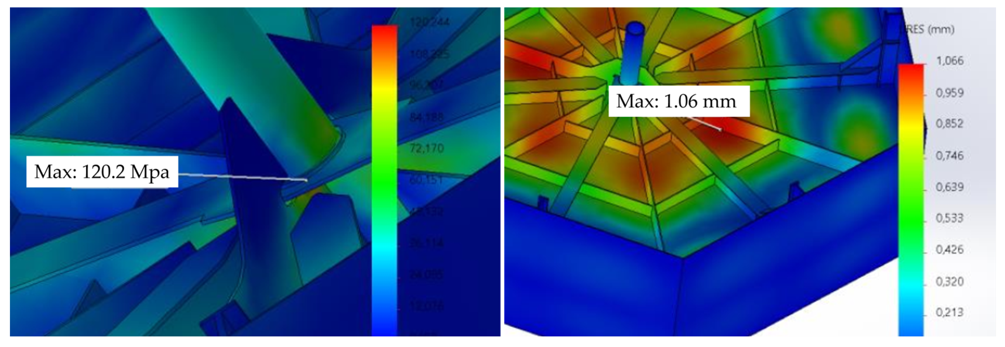
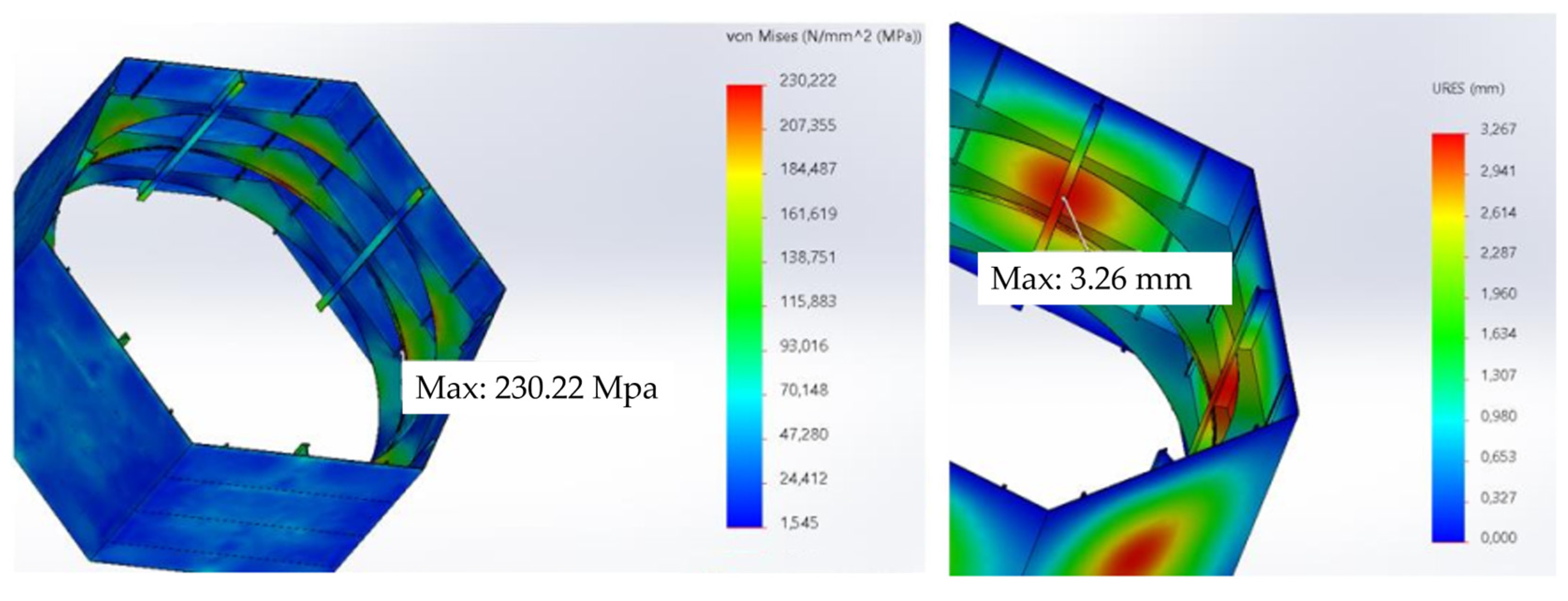
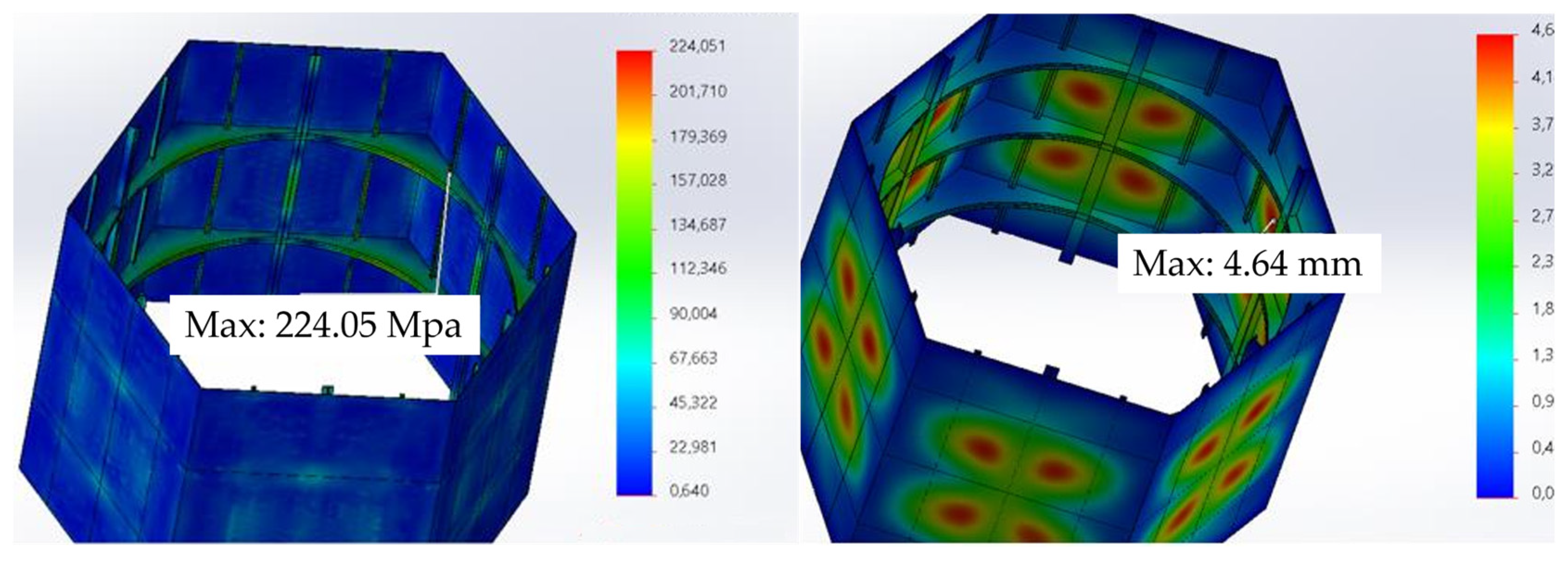
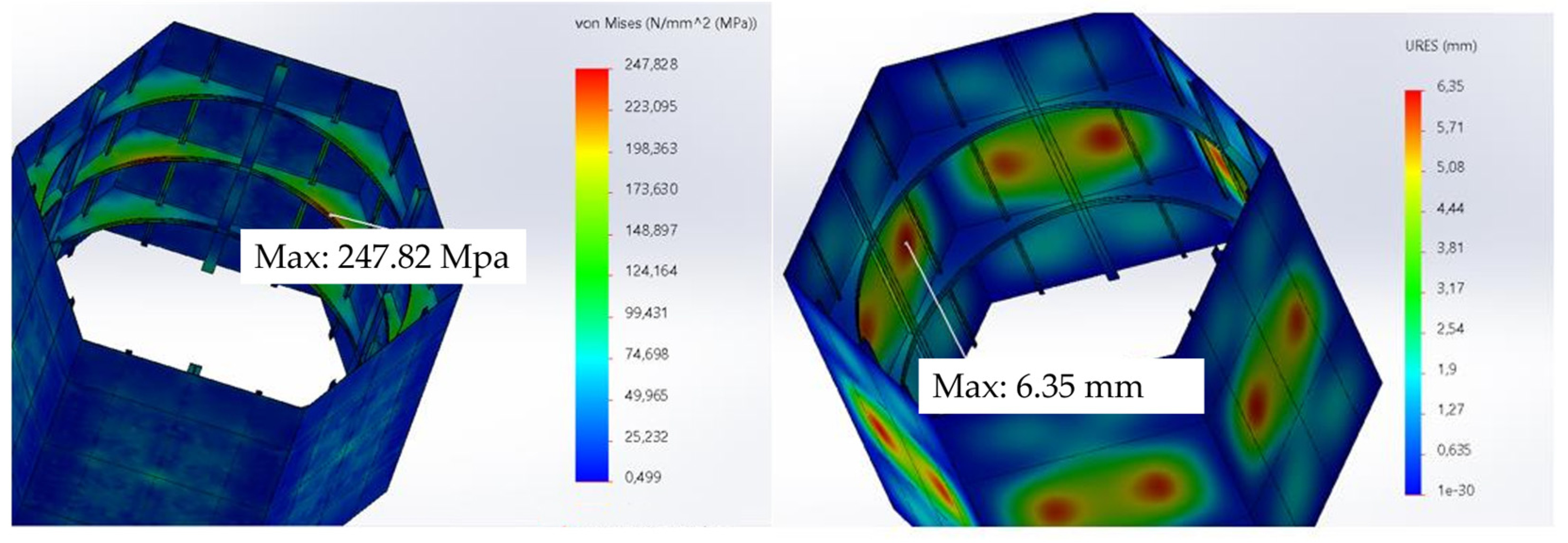
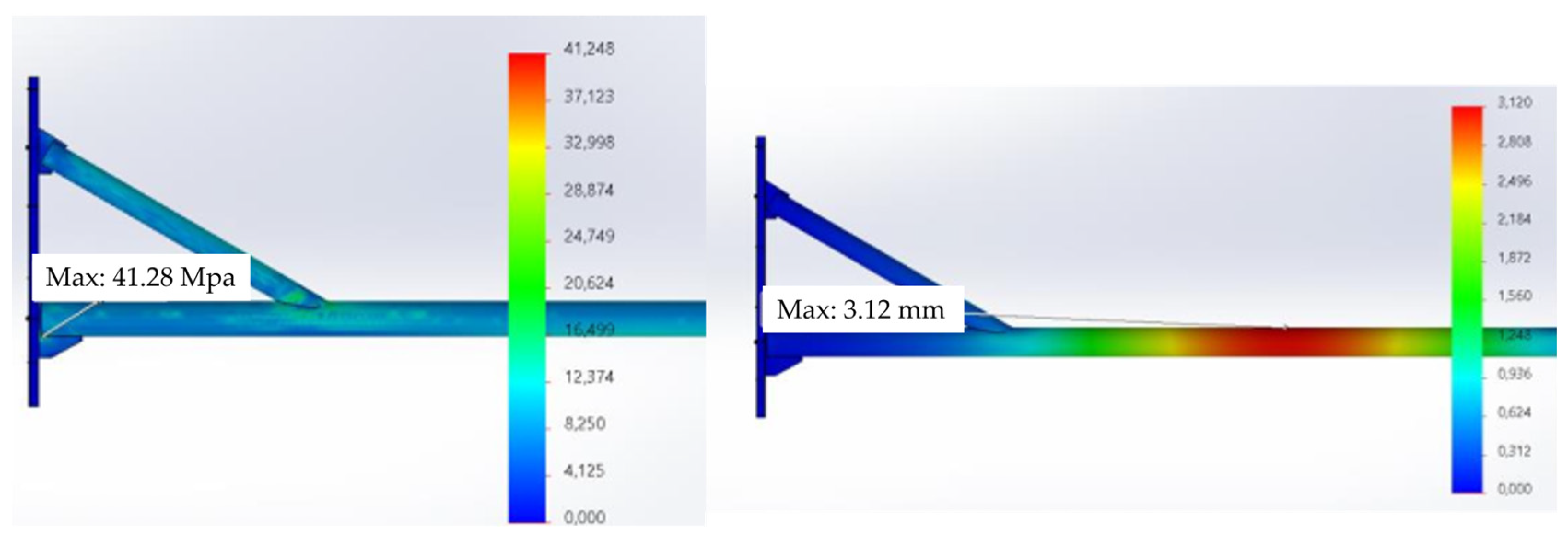
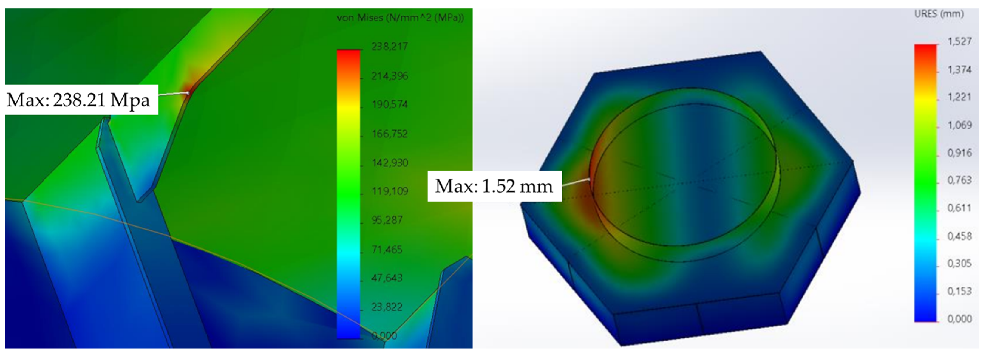
The proposed semi-submersible platform design was based on several previous tri-floater concepts. Among the principal features of the platform are the hexagonal shape of the floaters and the wind turbine tower positioning on one of the floaters. The structure was pre-sized in accordance with the DNV standard requirements for scantling. Based on the finite element analysis with a 13 m wave, it was found that the entire offshore structure could support the expected external forces of the Chilean waters within the range of the elastic strain, or below the yield strength of the material.
Only the weight of the platform structure was determined, using a density of 8000 kg/m3 to consider the plates’ welding and bolting. Then, we compared the weight of the proposed platform of 1172 tons with the weight used in previous studies [10,18], where the steel mass was estimated at 1900 and 1582 tons, respectively. It can be concluded that there is a reduction of 728 tons with Lefebvre’s model and 410 tons with Urra’s model.
The center of gravity of the structure, including the ballast and the weight of the support structure, wind turbine model, and tower, are shown in Table 13. 
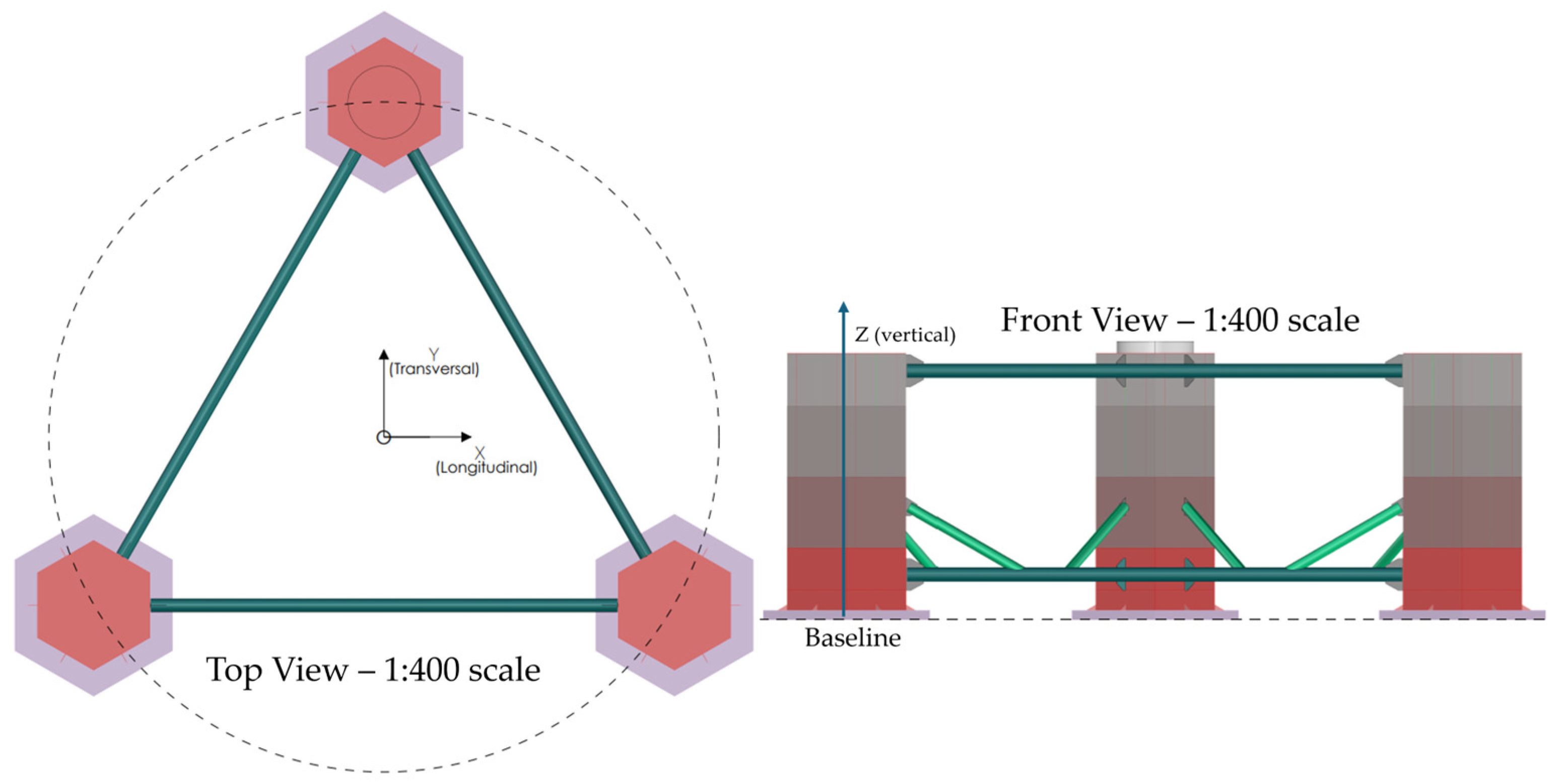
Figure 17 has a different view of the proposed platform structure to show the defined reference system, and the vertical center of gravity is located 22 m from the baseline. This value is similar to the one reported by Lefebvre et al. [10], and represents an adequate weight distribution. Nevertheless, the final position of the center of gravity will be adjusted after a large-angle stability analysis and a complementary hydrodynamic response study; both evaluations are outside the scope of this research work.

5. Conclusions

This paper discussed the early stage of the creation of a novel structural model of a semi-submersible platform that could support a 5 MW wind turbine generator in Chilean waters. This study began by defining the specific objectives, such as determining the platform’s geometric characteristics and following the DNV-GL classification society’s standards. Then, the structural calculation, or the scantling and steel weight, was determined. Finally, the physical properties, like the center of mass and the extreme condition of a 13 m wave, were simulated by a finite element analysis. This generated a set of drawings of a very early-stage design. The main findings are summarized as follows:
  • The proposed tri-floater platform design reduces the weight by more than 30% compared with other proposed models, and the wind turbine tower positioning on one of the floaters reduces the raw materials and makes the installation process easier.
  • The support structure meets the DNV design rules for the given wave conditions.
  • The finite element analysis includes a 13 m wave that suggests the good performance of the proposed tri-floater platform under Chilean environmental conditions and, more specifically, Valdivia´s coast.
  • This early-stage design offers a conceptual and preliminary step for floating support structure designs in Chile. However, a dynamic analysis of the stability and mooring system needs to be conducted to propose a complete and detailed design.
  • A scaled model of the proposed tri-floater platform should be evaluated to validate and understand the hydrodynamic behavior of the system.

Author Contributions

Conceptualization, Y.G., G.T. and M.Y.M.; methodology, Y.G. and V.P.; software, J.M.A. and C.C.; validation, C.T. and M.Y.M.; formal analysis, M.Y.M. and Y.G.; investigation, M.Y.M. and Y.G.; resources, G.T.; writing—original draft preparation, Y.G.; writing—review and editing, M.Y.M., G.T., C.C., V.P., J.M.A. and C.T.; project administration, M.Y.M. and G.T. All authors have read and agreed to the published version of the manuscript.

Funding

The authors acknowledge the partial funding from ANID IDEA ID23I10258.

Institutional Review Board Statement

Not applicable.

Informed Consent Statement

Not applicable.

Data Availability Statement

This article contains all the data that were generated and they are presented in the form of figures or tables.

Acknowledgments

The authors would like to express their gratitude to the Wave/Towing Tank personnel at the Universidad Austral de Chile for the information and discussions.

Conflicts of Interest

The authors declare no conflicts of interest.

References

  1. Laura, C.-S.; Vicente, D.-C. Life-cycle cost analysis of floating offshore wind farms. Renew. Energy 2014, 66, 41–48. [Google Scholar] [CrossRef]
  2. Hughes, L.; Longden, T. Offshore wind power in the Asia-Pacific: Expert elicitation on costs and policies. Energy Policy 2024, 184, 113842. [Google Scholar] [CrossRef]
  3. Shadman, M.; Roldan-Carvajal, M.; Pierart, F.G.; Haim, P.A.; Alonso, R.; Silva, C.; Osorio, A.F.; Almonacid, N.; Carreras, G.; Maali Amiri, M. A review of offshore renewable energy in South America: Current status and future perspectives. Sustainability 2023, 15, 1740. [Google Scholar] [CrossRef]
  4. Tampier, G.; Cifuentes, C.; Parra, C.; Aziares, N.; Cardenas, R.; Alvarez, K. Offshore Wind Technologies for Chile: Perspectives and Challenges; Marine Energy Research and Innovation Center (MERIC): Santiago de Chile, Chile, 2024. [Google Scholar]
  5. Faraggiana, E.; Giorgi, G.; Sirigu, M.; Ghigo, A.; Bracco, G.; Mattiazzo, G. A review of numerical modelling and optimisation of the floating support structure for offshore wind turbines. J. Ocean. Eng. Mar. Energy 2022, 8, 433–456. [Google Scholar] [CrossRef]
  6. Duarte, T.; Price, S.; Peiffer, A.; Pinheiro, J.M. Windfloat atlantic project: Technology development towards commercial wind farms. In Proceedings of the Offshore Technology Conference, Houston, TX, USA, 2–5 May 2022; p. D021S016R003. [Google Scholar]
  7. Allen, C.; Viscelli, A.; Dagher, H.; Goupee, A.; Gaertner, E.; Abbas, N.; Hall, M.; Barter, G. Definition of the UMaine VolturnUS-S Reference Platform Developed for the IEA Wind 15-Megawatt Offshore Reference wind Turbine; National Renewable Energy Lab. (NREL): Golden, CO, USA, 2020. [Google Scholar]
  8. Liu, L.; Zhao, H.; Xu, W.; Yuan, R.; Guo, Y. Structural strength analysis of a tri-Floater floating foundation for offshore VAWT. J. Ocean. Univ. China 2018, 17, 753–762. [Google Scholar] [CrossRef]
  9. Huijs, F.; de Bruijn, R.; Savenije, F. Concept design verification of a semi-submersible floating wind turbine using coupled simulations. Energy Procedia 2014, 53, 2–12. [Google Scholar] [CrossRef]
  10. Lefebvre, S.; Collu, M. Preliminary design of a floating support structure for a 5 MW offshore wind turbine. Ocean. Eng. 2012, 40, 15–26. [Google Scholar] [CrossRef]
  11. Kim, T.; Natarajan, A.; Lovera, A.; Julan, E.; Peyrard, C.; Capaldo, M.; Huwart, G.; Bozonnet, P.; Guiton, M. A comprehensive code-to-code comparison study with the modified IEA15MW-UMaine Floating Wind Turbine for H2020 HIPERWIND project. J. Phys. Conf. Ser. 2022, 2265, 042006. [Google Scholar] [CrossRef]
  12. GustoMSC E.C. NOV A. Tri-Floater Floating Offshore Wind Turbine Foundation: Robust and Cost-Effective: Technical Report. 2021. Available online: https://www.nov.com/products/tri-floater-floating-offshore-wind-turbine-foundation (accessed on 9 May 2023).
  13. Sandua-Fernández, I.; Vittori, F.; Eguinoa, I.; Cheng, P. Impact of hydrodynamic drag coefficient uncertainty on 15 MW floating offshore wind turbine power and speed control. J. Phys. Conf. Ser. 2022, 2362, 012037. [Google Scholar] [CrossRef]
  14. Amiri, M.M.; Shadman, M.; Estefen, S.F. A Review of Numerical and Physical Methods for Analyzing the Coupled Hydro–Aero–Structural Dynamics of Floating Wind Turbine Systems. J. Mar. Sci. Eng. 2024, 12, 392. [Google Scholar] [CrossRef]
  15. Mattar, C.; Cabello-Españon, F.; Alonso-de-Linaje, N.G. Towards a future scenario for offshore wind energy in Chile: Breaking the paradigm. Sustainability 2021, 13, 7013. [Google Scholar] [CrossRef]
  16. DNVGL-ST-0119; Floating Wind Turbine Structures. Det Norske Veritas and Germanischer Lloyd Bærum: Høvik, Norway, 2018.
  17. DNVGL-RP-C205; Recommended Practice, Environmental Conditions and Environmental Loads. Det Norske Veritas and Germanischer Lloyd Bærum: Høvik, Norway, 2017.
  18. Urra Sergio Andres. Diseño Estructural Preliminar de Plataforma Eolica Flotante; Instituto de Ciencias Navales y Maritimas, Universidad Austral de Chile: Valdivia, Chile, 2022. [Google Scholar]
  19. Johannesen, I.P.; Ahumada, J.M.; Tampier, G.; Grüter, L.; Cifuentes, C. Numerical and experimental analysis of a wave energy converter in extreme waves. Ocean. Syst. Eng. 2023, 13, 225–245. [Google Scholar]
  20. Jonkman, J.; Butterfield, S.; Musial, W.; Scott, G. Definition of a 5-MW Reference Wind Turbine for Offshore System Development; National Renewable Energy Lab. (NREL): Golden, CO, USA, 2009. [Google Scholar]
  21. Jonkman, J.M. Loads Analysis of a Floating Offshore Wind Turbine Using Fully Coupled Simulation; National Renewable Energy Lab. (NREL): Golden, CO, USA, 2007. [Google Scholar]
  22. Rodriguez-Lôpez, E.; Moreno-Narrillos, C.; Rueda-Guglieri, F.; Yáñez-González, Á. Time domain hydrodynamics at panel level: An application to the structural analysis of Telwind. J. Phys. Conf. Ser. 2022, 2257, 012009. [Google Scholar] [CrossRef]
  23. Principal Power Company. Principle Power Expands WindFloat® Product Portfolio, Launches WindFloat F; Principal Power Company: Emeryville, CA, USA, 2023. [Google Scholar]
  24. Rueda Bayona, J.G. Caracterización Hidromecánica de Plataformas Marinas en Aguas Intermedias Sometidas a Cargas de Oleaje y Corriente Mediante Modelación Numérica; Universidad Nacional de Colombia: Bogotá, Colombia, 2015. [Google Scholar]
  25. Llorca, J.; Herrero, J.M.G.; Ametller, S.; del Estado, P. Rom 2.0-11: Recomendaciones para el Proyecto y Ejecución en obras de Atraque y Amarre; Puertos del Estado: Madrid, Spain, 2012. [Google Scholar]
  26. N-004; Design of Steel Structures; Rev. 2. NORSOK Standard: Oslo, Norway, 2004.
Figure 1. Classification diagram of the three main types of FW platforms utilized in the industry: ballast stability, buoyancy stability, and mooring stabilization.
Jmse 12 01951 g001
Figure 2. (a) Configuration of VolturnUS [13] and (b) WindFloat Atlantic offshore platforms [14].
Jmse 12 01951 g002
Figure 3. Intended offshore area.
Jmse 12 01951 g003
Figure 4. Proposed semi-submersible platform.
Jmse 12 01951 g004
Figure 5. Floaters’ wall pressures calculated by DNV standard.
Jmse 12 01951 g005
Figure 6. Plate reinforcement distribution.
Jmse 12 01951 g006
Figure 7. Bulkhead reinforcement distribution.
Jmse 12 01951 g007
Figure 8. Displacement and stress of lower floater cover.
Jmse 12 01951 g008
Figure 9. Displacement and stress of upper floater cover.
Jmse 12 01951 g009
Figure 10. Displacement and stress of bottom bulkhead 3.
Jmse 12 01951 g010
Figure 11. Displacement and stress of compartment 4 plates.
Jmse 12 01951 g011
Figure 12. Displacement and stress of vertical bulkhead 1.
Jmse 12 01951 g012
Figure 13. Displacement and stress of vertical bulkhead 2.
Jmse 12 01951 g013
Figure 14. Displacement and stress of floater joining elements.
Jmse 12 01951 g014
Figure 15. Buckling factor of safety for joining elements.
Jmse 12 01951 g015
Figure 16. Displacement and stress of ring support.
Jmse 12 01951 g016
Figure 17. Coordinate system and vertical center of gravity for the proposed platform.
Jmse 12 01951 g017
Table 1. Main characteristics of 5 MW offshore wind turbine.
ParameterValueUnits
Rotor Diameter126m
Rotor Height12.5m
Hub Height90m
Air gap27m
Tower Height77.6m
Diameter of the Tower Base6.5m
Diameter of the Tower Upper Section3.87m
Nacelle Weight240Ton
Rotor Weight111Ton
Hub Weight56.78Ton
Tower Weight347.46Ton
Vertical Center of Gravity of Nacelle90m
Vertical Center of Gravity of Rotor90m
Vertical Center of Gravity of Hub90m
Vertical Center of Gravity of Tower38.234m
Table 2. Main dimensions of proposed semi-submersible platform.
ParameterValueUnits
Diameter10m
Radial distance from the center30m
Beam52m
Length45m
Column height22.5m
Maximum draft14m
Table 3. Wind and waves design conditions.
ParameterValueUnits
Significant wave height9.65m
Peak wave period14.8s
Wind velocity25m/s
Table 4. Properties of structural steel S275.
ParameterValueUnits
Yield strength275MPa
Ultimate strength370–530MPa
Young modulus200MPa
Poisson coefficient0.3-
Density8000kg/m3
Table 5. Wind forces on tower.
ParameterValueUnits
Area632.11m2
Wind force shape coefficient (C)0.4-
Wind velocity (Ut)25m/s
Air density1226kg/m3
Basic wind pressure (Q)383.125kg/ms2
Wind force (Fw)96.871kN
Application point of c/r to the base35m
Momentum c/r of the base3390kN-m
Table 6. Wind forces on each floater.
ParameterValueUnits
Area115.72m2
Wind force shape coefficient (C)1-
Wind velocity (Ut)25m/s
Air density1226kg/m3
Basic wind pressure (Q)383.125kg/ms2
Wind force (Fw)44kN
Table 7. Wave and current forces on each floater.
ParameterValueUnits
Significant wave height (H)9.65m
Drag coefficient (Cd)1-
Inertia coefficient (Cm)1-
Frequency wave (W)0.425rad/s
Current speed (U)2.6m/s
Current acceleration (u)0.87m/s2
Wave period (T)14.8S
Density (ρ)1.025Ton/m3
Area (A)173.66m2
Submerged volume (V)909m3
Hydrodynamic forces (Fh)1411.9kN
Table 8. Bulkhead pressure design results 1.
BulkheadPressure Design (kPa)
15
283.465
3176.062
1 Figure 4 also shows bulkheads’ location.
Table 9. Plate thickness 1.
CompartmentPlate Thickness (mm)
18
210
312
418
1 Figure 5 shows plates’ locations.
Table 10. Bulkhead thickness.
BulkheadThickness (mm)
18
220
330
Table 11. Horizontal bulkhead stress and deformation results.
Bulkhead NumberPressure Design (kPa)Stress (MPa)Deformation (mm)
130 1113.81.6
283.46135.41.79
3176.062120.21.06
1 Pressure design on bulkhead 3 is 5 kPa, but it was validated with 30 kPa as extreme condition.
Table 12. Compartment plates’ stress and deformation results.
Compartment PlatesPressure Design (kPa)Stress (MPa)Deformation (mm)
261.393217.412.65
3137.645226.723.14
4214.854230.223.26
Table 13. Center of gravity.
ComponentMass (ton)Longitudinal CG (m)Transversal CG (m)Vertical CG (m)
Platform117200.37.65
Wind tower755.2403086.5
Total, no ballast1927.24011.938.5
Ballast1700003.21
Total with ballast3627.24011.922
Disclaimer/Publisher’s Note: The statements, opinions and data contained in all publications are solely those of the individual author(s) and contributor(s) and not of MDPI and/or the editor(s). MDPI and/or the editor(s) disclaim responsibility for any injury to people or property resulting from any ideas, methods, instructions or products referred to in the content.

