Article

Energy Efficiency Maximization for Multi-UAV-IRS-Assisted Marine Vehicle Systems

1
Information Science and Technology College, Dalian Maritime University, Dalian 116026, China
2
Navigation College, Dalian Maritime University, Dalian 116026, China
*
Author to whom correspondence should be addressed.
J. Mar. Sci. Eng. 2024, 12(10), 1761; https://doi.org/10.3390/jmse12101761
Submission received: 9 September 2024 / Revised: 30 September 2024 / Accepted: 2 October 2024 / Published: 4 October 2024
(This article belongs to the Special Issue Unmanned Marine Vehicles: Navigation, Control and Sensing)

Abstract

:
Mobile edge computing is envisioned as a prospective technology for supporting time-sensitive and computation-intensive applications in marine vehicle systems. However, the offloading performance is highly impacted by the poor wireless channel. Recently, an Unmanned Aerial Vehicle (UAV) equipped with an Intelligent Reflecting Surface (IRS), i.e., UIRS, has drawn attention due to its capability to control wireless signals so as to improve the data rate. In this paper, we consider a multi-UIRS-assisted marine vehicle system where UIRSs are deployed to assist in the computation offloading of Unmanned Surface Vehicles (USVs). To improve energy efficiency, the optimization problem of the association relationships, computation resources of USVs, multi-UIRS phase shifts, and multi-UIRS trajectories is formulated. To solve the mixed-integer nonlinear programming problem, we decompose it into two layers and propose an integrated convex optimization and deep reinforcement learning algorithm to attain the near-optimal solution. Specifically, the inner layer solves the discrete variables by using the convex optimization based on Dinkelbach and relaxation methods, and the outer layer optimizes the continuous variables based on the Multi-Agent Twin Delayed Deep Deterministic Policy Gradient (MATD3). The numerical results demonstrate that the proposed algorithm can effectively improve the energy efficiency of the multi-UIRS-assisted marine vehicle system in comparison with the benchmarks.

1. Introduction

Marine autonomous systems and wireless technologies have promoted the development of many new marine applications, such as marine monitoring, and intelligent navigation, posing challenges in processing computation-intensive tasks [1,2]. Unmanned Surface Vehicles (USVs) and Unmanned Aerial Vehicles (UAVs) have emerged as advanced marine intelligent devices equipped with sensing modules, computing modules, and communication modules to collect, analyze, and process marine data, including hydrological and meteorological information, image/voice/video, and obstacle detection, to make real-time prediction on vessel behaviors, and provide accurate and efficient navigation services for vessels. However, these marine devices may suffer severe energy capacity and computation resource limitations for processing lots of computation-intensive tasks. In this context, edge computing technology provides a promising paradigm for resource-limited marine devices, which has attracted significant attention in academia and industry [3,4,5]. In particular, the computation tasks can be offloaded to and processed at the edge servers with computation capability, which are usually installed on the communication infrastructures. However, due to the limitation of marine infrastructures and the special characteristics of marine environments, the direct communication links between marine devices and edge servers are highly impacted by obstacles, making it difficult to support massive data offloading in time [6,7].
Recently, an Intelligent Reflecting Surface (IRS) has shown significant advantages in enhancing signal transmission quality by reshaping the wireless propagation channel [8,9,10,11]. Specifically, the IRS is a digitally-controlled metasurface composed of a large number of passive reflection elements with adjustable phase shifts [12,13]. Existing works investigate the benefits of utilizing an IRS to assist computation offloading from users to edge servers [14,15]. For instance, Chen et al. [16] propose a sum computation rate maximizing problem by optimizing the computational model decision, time allocation, and IRS beamforming, which is solved by a novel penalty-based successive convex approximation method. Yang et al. [17] propose a total energy consumption minimization problem by optimizing the binary offloading mode, computation resources, offloading power, offloading time, and IRS phase shifts in the IRS-aided mobile edge computing system, which is solved by greedy-based and penalty-based algorithms. The aforementioned works consider the IRS-assisted edge computing network, where the IRS is deployed on the building facade or base station, which is still challenging to construct the dominant Line-of-Sight (LoS) channel links.
Thanks to the advantages of the high mobility of UAVs, the IRS mounted on a UAV (UIRS) can provide on-demand deployment in a Three-Dimensional (3D) space [18,19]. In addition, the channel in which the UIRS participates has a high LoS probability, further enhancing the signal quality. According to the advantages of the UIRS, there have been existing works on UIRS-assisted edge computing systems [20,21]. Zhai et al. [22] propose an energy efficiency maximization problem by optimizing the UIRS trajectory, passive beamforming, and computation resource allocation, and apply the successive convex approximation and Dinkelbach method to solve the optimization problem. Ai et al. [23] propose an IRS-aided wireless inland ship mobile edge computing network that minimizes energy consumption through the joint design of the offloading percentage of USVs, transmission power, UIRS trajectory, and phase shifts, and develop an enhanced block coordinate descent method to solve the optimization problem.
In marine vehicle systems, insufficient spectrum resources and huge computation demands cause several challenges in the energy consumption of USVs and UAVs as they are resource-constrained devices. USVs offload partial workloads to the shore BS, with powerful computation resources to reduce the pressure of local computing, but increase the transmission energy consumption and transmission time. In this process, the UIRS is expected to adjust its positions and phase shifts to obtain better channel conditions between USVs and the shore BS for improving the data rate. In addition, the works in [18,24,25,26] demonstrate that multiple IRSs in the wireless communication system can achieve performance improvement in the data rate compared to the single IRS-assisted system. However, these works focus on the communication resource allocation and phase shift design with the assistance of multiple static IRSs. Note that multi-UIRS studies are difficult to extend directly from the single UIRS due to complex coordination and cooperation, distributed deployment, and communication resource sharing. Additionally, the total energy consumption increases as the number of UAVs increases correspondingly [27]. In this context, to consider both the computation bits and energy consumption, there have been studies on energy efficiency, which is defined as the ratio of the computation bits to the energy consumption [28]. In this paper, energy efficiency is a critical issue in the marine vehicle system owing to the fact that USVs and UIRSs are generally energy-constrained and computation resource-constrained. To the best of our knowledge, there have been no prior studies of multi-UIRS-assisted computation offloading on providing an energy efficiency evaluation.
In this paper, we propose a resource management and trajectory design scheme in the multi-UIRS-assisted marine vehicle system. Each UAV installed with an IRS is deployed to assist the USVs in offloading partial workloads to the shore BS equipped with the edge server. To enhance energy efficiency, the association relationships, computation resources, multi-UIRS phase shifts, and trajectories are jointly optimized. In terms of optimization methods, existing works mainly rely on convex optimization theories, such as, [16,17,22,23]. These traditional methods pose design challenges in the complex and dynamic channel environment that incur high computational costs [29]. Fortunately, reinforcement learning methods can be used to solve most complex optimization problems [30,31]. However, the existing reinforcement learning algorithms cannot solve the hybrid continuous and discrete variables optimization problem directly. Therefore, we propose an integrated Convex Optimization and Multi-Agent Twin Delayed Deep Deterministic Policy Gradient (CO-MATD3) algorithm to solve the formulated optimization problem with mixed continuous and discrete variables. Finally, extensive simulation results demonstrate that the proposed CO-MATD3 algorithm can improve energy efficiency, in comparison with the benchmarks. The main contributions are summarized as follows:
  • In the multi-UIRS-assisted marine vehicle system, an energy efficiency maximization (EEM) optimization problem is formulated by jointly optimizing the association relationships between UIRSs and USVs, computation resources of USVs, multi-UIRS phase shifts, and multi-UIRS 3D trajectories, subject to the computation data demand threshold constraints.
  • The formulated optimization problem is a mixed integer nonlinear programming problem with discrete variables, i.e., association relationships, and continuous variables, i.e., computation resources, phase shifts, and trajectories, which is well known to be NP-hard. To efficiently solve the challenging problem, we decompose the original problem into two layers to solve discrete and continuous variables, respectively.
  • Then, we propose a CO-MATD3 algorithm, which is an integrated convex optimization and deep reinforcement learning algorithm designed to facilitate collaborative optimization. Specifically, in the inner layer, the Dinkelbach method and relaxation method are applied to optimize the association relationships. In the outer layer, a distributed cooperative deep reinforcement learning algorithm, i.e., the Multi-Agent Twin Delayed Deep Deterministic Policy Gradient (MATD3), is developed to optimize continuous variables.
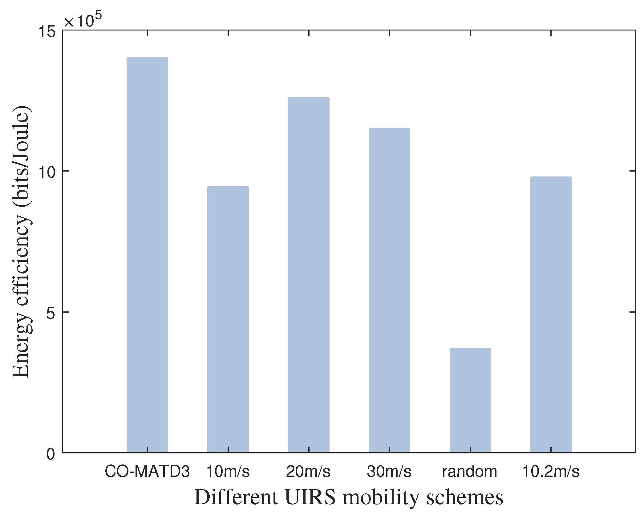
  • Finally, the simulation results demonstrate the efficient training convergence and effectiveness of the proposed CO-MATD3 algorithm in optimizing energy efficiency. In addition, we find that our proposed CO-MATD3 algorithm has the capability to optimize multi-UIRS trajectories according to the dynamic locations of USVs to improve energy efficiency. The simulation results show that the performance of the proposed algorithm is superior to other benchmarks under different simulation conditions, such as the number of UIRSs, the number of USVs, computation resources, and transmission power.
The remainder of this paper is organized as follows. A multi-UIRS-assisted marine vehicle system model and energy efficiency maximization problem are introduced in Section 2. The CO-MATD3 algorithm to solve the optimization problem is proposed in Section 3. The numerical results are presented in Section 4, and finally, the paper is concluded in Section 5.
Notations: x denotes the transpose matrix of vector x ; x H denotes the conjugate transpose matrix of vector x ; X Y denotes the Kronecker product of two matrices X and Y ; and C X × Y denotes the space of the X × Y complex matrix.

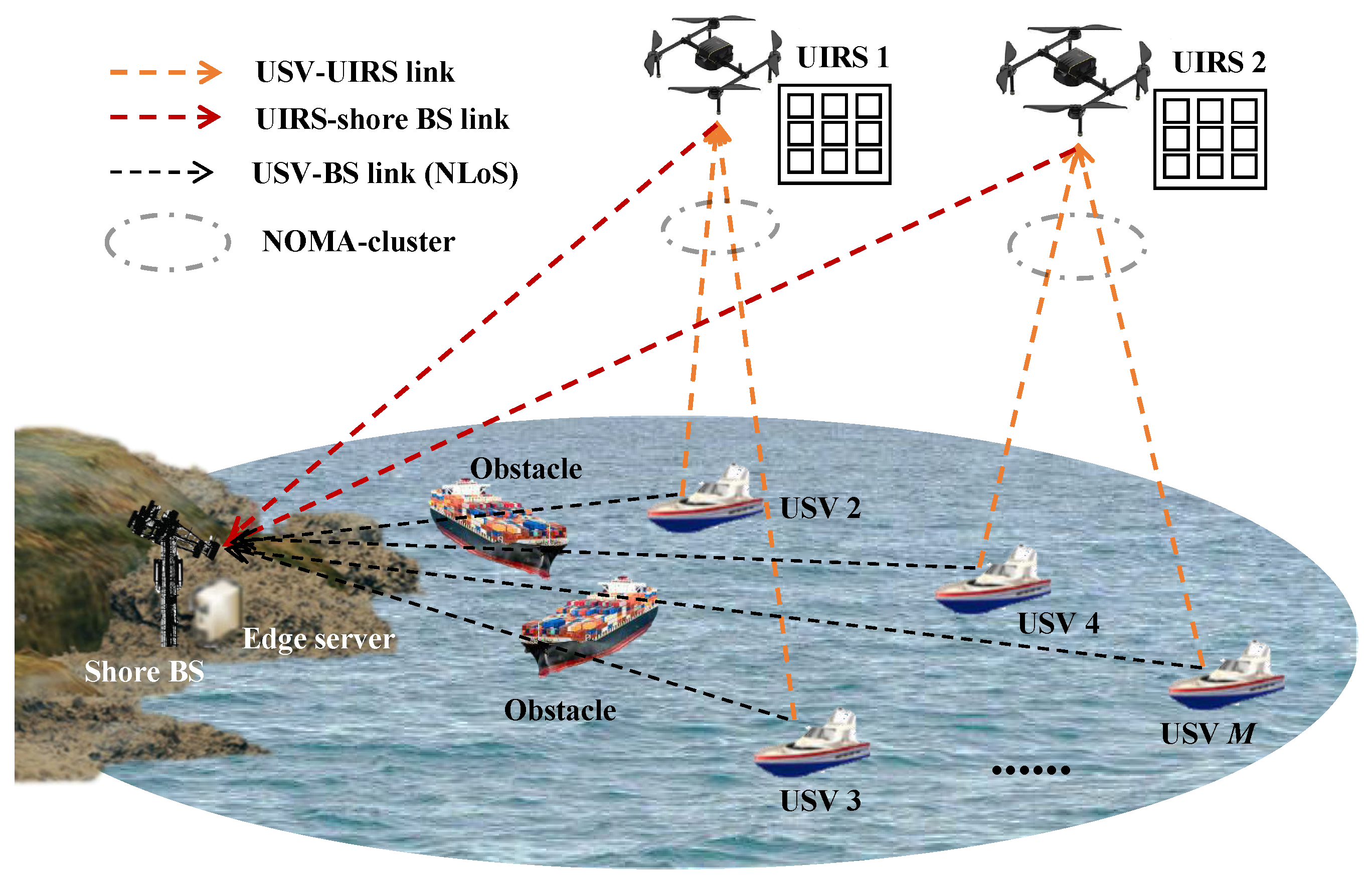
2. System Model And Problem Formulation

2.1. Network Model

We consider a multi-UIRS-assisted marine vehicle system as illustrated in Figure 1, which consists of a group of USVs denoted as M = { 1 , 2 , , M } , a group of UIRSs denoted as N = { 1 , 2 , , N } , and a shore BS. The shore BS equipped with edge servers has powerful computation capability so that it can execute offloading data from USVs. The resource-constrained USVs can either process their computation tasks locally or offload partial workloads to the shore BS. Considering the complex marine environment, the communication channels between USVs and the shore BS are often blocked by vessels in offshore areas. Multiple UIRSs are employed to provide reflecting links between USVs and the shore BS. We suppose that the perfect channel state information can be obtained by the existing channel estimation methods. The UIRS n is composed of K n = K n , x × K n , y reflection elements, where K n , x and K n , y denote the number of elements of the nth UIRS along the x-axis and y-axis, respectively. The reflection coefficient matrix of the UIRS n is denoted as Θ n = diag { e j φ 1 , 1 , , e j φ k n , x , k n , y , , e j φ K n , x , K n , y } , where φ k n , x , k n , y [ 0 , 2 π ] ,   k n , x = { 1 , , K n , x } ,   k n , y = { 1 , , K n , y } denotes the ( k n , x , k n , y ) th reflection element of the nth UIRS programmable phase shift, and  j denotes the imaginary unit. We adopt that several USVs form a Non-Orthogonal Multiple Access (NOMA) cluster to offload workloads to the shore BS via the associated UIRS by the NOMA protocol.
In the 3D Cartesian coordinate system, the x-axis and y-axis denote the horizontal coordinate, respectively, and the z-axis denotes the vertical coordinate over the sea level. The location of the USV m is denoted by L m = { x m , y m , 0 } , m M . The location of the shore BS is denoted by L 0 = { x 0 , y 0 , z 0 } . For convenience, the period is divided into T equal time slots denoted as T = { 1 , 2 , , T } , with the duration of τ . The location of the UIRS n at time slot t is denoted by L n ( t ) = { x n ( t ) , y n ( t ) , z n ( t ) } . The distance between the USV m and the UIRS n at time slot t is d m , n ( t ) = L m L n ( t ) ; the distance between the UIRS n and the shore BS at time slot t is d n , 0 ( t ) = L n ( t ) L 0 ; the distance between the USV m and the BS is d m , 0 = L m L 0 .

2.2. Channel Model

The Rician fading is adopted for both channel models from the USV to the UIRS (USV-UIRS link) and from the UIRS to the shore BS (UIRS-BS link). Thus, the channel gain h m , n ( t ) C 1 × K n between the USV m and the UIRS n, and  h n , 0 ( t ) C K n × 1 between the UIRS n and the shore BS at time slot t are
h m , n ( t ) = ρ 0 d m , n β m , n ( t ) h ˜ m , n ( t ) , m M , n N , t T ,
and
h n , 0 ( t ) = ρ 0 d n , 0 β n , 0 ( t ) h ˜ n , 0 ( t ) , n N , t T ,
respectively, where ρ 0 denotes the channel gain at the reference distance, and β m , n and β n , 0 denote the path loss exponent. The Rician fading parameters are denoted as h ˜ m , n ( t ) = ξ m , n / ( 1 + ξ m , n ) h m , n LoS ( t ) + 1 / ( 1 + ξ m , n ) h m , n NLoS ( t ) and h ˜ n , 0 ( t ) = ξ n , 0 / ( 1 + ξ n , 0 ) h n , 0 LoS ( t ) + 1 / ( 1 + ξ n , 0 ) h n , 0 NLoS ( t ) [32], where ξ m , n and ξ n , 0 denote the Rician factors. h m , n LoS ( t ) and h n , 0 LoS ( t ) are the LoS components. h m , n NLoS ( t ) CN ( 0 , I K n ) and h n , 0 NLoS ( t ) CN ( 0 , I K n ) are the Non-LoS (NLoS) components [18].
The LoS links h m , n LoS ( t ) and h n , 0 LoS ( t ) at time slot t are [29]
h m , n LoS ( t ) = [ 1 , e j 2 π d λ ϖ ^ m , n ( t ) , , e j 2 ( K n , x 1 ) π d λ ϖ ^ m , n ( t ) ] [ 1 , e j 2 π d λ ϖ ˇ m , n ( t ) , , e j 2 ( K n , y 1 ) π d λ ϖ ˇ m , n ( t ) ] , m M , n N , t T ,
and
h n , 0 LoS ( t ) = [ 1 , e j 2 π d λ ϱ ^ n , 0 ( t ) , , e j 2 ( K n , x 1 ) π d λ ϱ ^ n , 0 ( t ) ] [ 1 , e j 2 π d λ ϱ ˇ n , 0 ( t ) , , e j 2 ( K n , y 1 ) π d λ ϱ ˇ n , 0 ( t ) ] , n N , t T ,
respectively, where λ denotes the carrier wavelength, d denotes the separation distance, ϖ ^ m , n ( t ) = sin ϕ m , n ( t ) cos γ m , n ( t ) , ϖ ˇ m , n ( t ) = sin ϕ m , n ( t ) sin γ m , n ( t ) , ϱ ^ n , 0 ( t ) = sin ϕ n , 0 ( t ) cos γ n , 0 ( t ) , and ϱ ˇ n , 0 ( t ) = sin ϕ n , 0 ( t ) sin γ n , 0 ( t ) . The vertical and horizontal Angle of Arrivals (AoAs) from the USV m to the UIRS n are denoted by ϕ m , n ( t ) and γ m , n ( t ) , respectively. The vertical and horizontal Angle of Departures (AoDs) from the UIRS n to the shore BS are denoted by ϕ n , 0 ( t ) and γ n , 0 ( t ) , respectively. We have sin ϕ m , n ( t ) = | z n ( t ) | d m , n ( t ) , sin γ m , n ( t ) = | x n ( t ) x m | ( x n ( t ) x m ) 2 + ( y n ( t ) y m ) 2 , cos γ m , n ( t ) = | y n ( t ) y m | ( x n ( t ) x m ) 2 + ( y n ( t ) y m ) 2 , sin ϕ n , 0 ( t ) = | z n ( t ) z 0 | d n , 0 ( t ) , sin γ n , 0 ( t ) = | x n ( t ) x 0 | ( x n ( t ) x 0 ) 2 + ( y n ( t ) y 0 ) 2 , and cos γ n , 0 ( t ) = | y n ( t ) y 0 | ( x n ( t ) x 0 ) 2 + ( y n ( t ) y 0 ) 2 .
Adopting the two-ray signal propagation model for marine channels [1], the channel gain h m , 0 between the USV m and the shore BS is
h m , 0 = λ 4 π d m , 0 2 2 sin 2 π H m H 0 λ d m , 0 2 , m M ,
where H m denotes the antenna height of the USV m, and  H 0 denotes the antenna height of the shore BS.
After reflection and adjustment by the UIRS elements, the cascaded channel gain h m , n , 0 ( t ) C 1 × 1 from the USV m to the BS via the UIRS n at time slot t is
h m , n , 0 ( t ) = h m , 0 + ( h n , 0 ( t ) ) H Θ n ( t ) h m , n ( t ) , m M , n N , t T .
We introduce a binary variable α m , n ( t ) { 0 , 1 } , m M , n N , t T to represent the association relationship between the USV m and the UIRS n at time slot t. Specifically, α m , n ( t ) = 1 indicates that the USV m is associated with the UIRS n, and  α m , n ( t ) = 0 , otherwise. Therefore, the USVs are associated with the same UIRS to form a NOMA cluster for computation offloading, which can be denoted as M n ( t ) = { m | α m , n ( t ) = 1 , m M , n N , t T } .
We assume that the perfect successive interference cancellation is performed in the NOMA protocol [33]. The cascaded channel gain at the shore BS serving a group of USVs via the UIRS n at time slot t are sorted in descending order as follows:
h 1 , n , 0 ( t ) h m , n , 0 ( t ) h j , n , 0 ( t ) h M n , n , 0 ( t ) , m , j M n , n N , t T ,
that is, the signal received from the USV with the highest channel gain would be decoded first, while other USVs with lower channel gains would be considered as the co-channel interference. Thus, the data rate of the USV m at time slot t is
R m ( t ) = W log 2 1 + n = 1 N α m , n ( t ) p m ( t ) | h m , n , 0 ( t ) | 2 j = m + 1 M n ( t ) p j ( t ) | h j , n , 0 ( t ) | 2 + σ 2 , m M n ( t ) , t T ,
where W is the channel bandwidth, σ 2 is the noise power, and p m ( t ) is the transmission power of the USV m.

2.3. Task Execution Model

In this paper, each USV adopts the partial offloading method. The computation task data of each USV are composed of local computing by itself and edge computing by the edge server. Therefore, the computation rate of the USV is the sum of the local computing rate and the offloading data rate.
(1) Local computing: The local computation bits of the USV m at time slot t are
B m loc ( t ) = τ f m ( t ) C m , m M , t T ,
where C m denotes the number of CPU cycles required to finish one bit of data at the USV m, and  f m ( t ) denotes the computation resources of the USV m. The USV m has a maximum computation resource f m max constraint, satisfying
0 f m ( t ) f m max , m M , t T .
(2) Edge computing: In edge computing, the USV m offloads partial workloads to the shore BS. Considering the shore BS has a strong computation capability, it can process offloading workloads from USVs. Hence, the offloading bits of the USV m at time slot t are
B m off ( t ) = τ R m ( t ) , m M , t T .

2.4. Energy Consumption Model

The system energy consumption includes the following: (1) the local computation energy consumption of each USV E m loc ; (2) the offloading energy consumption of each USV E m off ; (3) the offloading energy consumption of the reflection elements on each UIRS E n ref ; and (4) the flight energy consumption of each UIRS E n fly . Note that the computation energy consumption of the shore BS is negligible due to the sufficient energy supply.
The local computation energy consumption of the mth USV at time slot t is
E m loc ( t ) = κ m B m loc ( t ) C m ( f m ( t ) ) 2 , m M , t T ,
where κ m is the effective switched capacitance of the USV m.
The offloading energy consumption of the mth USV at time slot t is
E m off ( t ) = τ n = 1 N α m , n ( t ) p m ( t ) , m M , t T .
The energy consumption of the reflection elements on the nth UIRS at time slot t is [34]
E n ref ( t ) = τ k = 1 K n p n , k ( t ) , n N , t T ,
where p n , k ( t ) is the power of the kth reflection element on the nth UIRS.
The flight energy consumption of the UIRS n at time slot t is given as [35]
E n fly ( t ) = τ ( P 0 1 + 3 ( v n hor ( t ) ) 2 U tip 2 + P 1 ( 1 + ( v n hor ( t ) ) 4 4 ( v ) 4 ( v n hor ( t ) ) 2 2 ( v ) 2 1 2 + P 2 v n ver ( t ) + 1 2 d 0 ρ S 0 A 0 ( v n hor ( t ) ) 3 ) , n N , t T ,
where U tip , d 0 , ρ , S 0 , A 0 , and  v denote the tip velocity of the rotor blade, fuselage drag ratio, air density, rotor solidity, rotor disc area, and average induced speed of the rotor, respectively. P 0 , P 1 , and  P 2 denote the blade profile power, induced power, and vertical propulsion power, respectively. v n hor ( t ) = ( x n ( t + 1 ) x n ( t ) ) 2 + ( y n ( t + 1 ) y n ( t ) ) 2 τ v max hor is the horizontal velocity for the nth UIRS, where v max hor is the maximum horizontal velocity, and  v n ver ( t ) = | z n ( t + 1 ) z n ( t ) | τ v max ver is the vertical velocity for the nth UIRS, where v max ver is the maximum vertical velocity.

2.5. Problem Formulation

In this paper, we define energy efficiency as the ratio of the total computation bits to the system’s energy consumption, which is expressed as
δ = B ^ E ^ = t = 1 T m = 1 M B m loc ( t ) + B m off ( t ) t = 1 T m = 1 M E m loc ( t ) + E m off ( t ) + n = 1 N E n ref ( t ) + ω E n fly ( t ) ,
where ω is the weighting element, B ^ is the total computation bits, and  E ^ is the system’s energy consumption.
For fulfilling the demand for specified computation bits of each USV at time slot t, we have
B m ( t ) = B m loc ( t ) + B m off ( t ) B m min , m M , t T ,
where B m min is the minimum task size requirement of the USV m at each time slot.
The association relationship between the USV m and the UIRS n at each time slot satisfies α m , n ( t ) { 0 , 1 } . Furthermore, each USV is assumed to associate with one UIRS at each time slot, satisfying
n = 1 N α m , n ( t ) = 1 , m M , t T .
Based on the above system model, we formulate an optimization problem to maximize the system’s energy efficiency. In the considered problem, the association relationships between USVs and UIRSs α = { α m , n ( t ) , m M , n N , t T } , computation resource allocation of USVs f = { f m ( t ) , m M , t T } , multi-UIRS phase shifts φ = { φ k n , x , k n , y ( t ) , k n , x K n , x , k n , y K n , y , n N , t T } , and multi-UIRS trajectories L = { L n ( t ) , n N , t T } are jointly optimized, subject to the computation data requirements of the USVs. Therefore, the EEM optimization problem is mathematically formulated as follows:
( EEM ) : max α , f , φ , L δ
s . t . B m ( t ) B m min , m M , t T ,
α m , n ( t ) { 0 , 1 } , m M , n N , t T ,
n = 1 N α m , n ( t ) = 1 , m M , t T ,
0 φ k n , x , k n , y ( t ) 2 π , k n , x K n , x , k n , y K n , y , n N , t T ,
0 f m ( t ) f m max , m M , t T ,
v n hor ( t ) v n , max hor , n N , t T ,
v n ver ( t ) v n , max ver , n N , t T .
Constraint (20) is the computation data requirement of each USV. Constraints (21) and (22) are the association limitations. Constraint (23) denotes the range of phase shifts. Constraint (24) limits the allocated computation resources of each USV. Constraints (25) and (26) are the mobility limitations.
The EEM is a MINLP problem with coupled variables, which motivates us to develop an integrated convex optimization and MATD3 for solving this challenge.

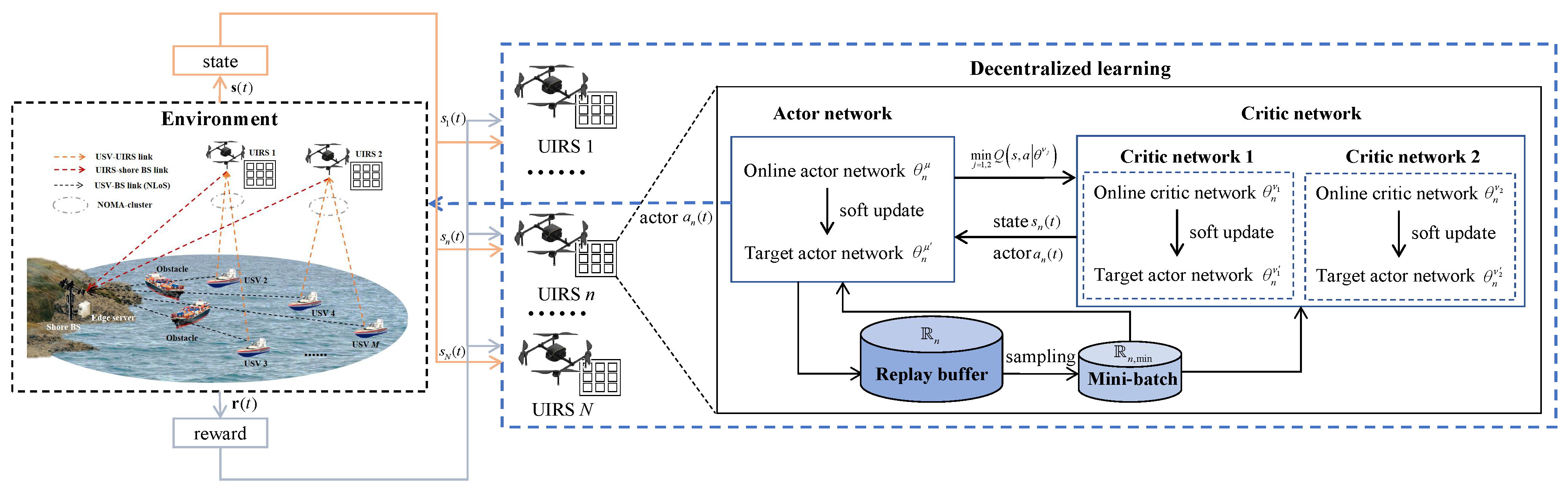
3. Proposed CO-MATD3 Algorithm

In this section, the CO-MATD3 algorithm is proposed to solve the challenge of the formulated EEM problem. Specifically, the EEM problem is decomposed into two layers, i.e., the EEM-Inner problem of the association relationships α , and the EEM-Outer problem of computation resources f , multi-UIRS phase shifts φ , and multi-UIRS trajectories L . The convex optimization is applied to tackle the EEM-Inner problem to obtain the feasible solutions of α . Then, the optimized f , φ , and L can be obtained by the MATD3 algorithm by substituting the obtained feasible α into the EEM-Outer problem.

3.1. EEM-Inner Problem

Due to the non-convex with fractional objective function, we convert it to a parametric formula by using the Dinkelbach method, which is rewritten as follows:
max α , f , φ , L B ^ δ E ^ .
When max { B ^ δ * E ^ } = 0 , the objective function has the optimal solution, and  δ * is the optimal energy efficiency.
The EEM-Inner problem aims to optimize the association relationships α under given computation resources f , the UIRS phase shifts φ , and the positions of UIRSs L . Therefore, the EEM-Inner problem is reformulated as follows:
( EEM - Inner - 1 ) : max α B ^ δ E ^
s . t . ( 20 ) , ( 21 ) , ( 22 ) .
To solve the binary constraint (21), we relax α m , n ( t ) as a continuous variable, which is expressed as
0 α m , n ( t ) 1 , m M , n N , t T .
Thus, the EEM-Inner-1 problem can be converted to
( EEM - Inner - 2 ) : max α B ^ δ E ^
s . t . 0 α m , n ( t ) 1 , m M , n N , t T ,
n = 1 N α m , n ( t ) = 1 , m M , t T ,
τ R m ( t ) B m min B m loc ( t ) , m M , t T .
Note that the association relationships and decoding order of the NOMA cluster are coupled; the EEM-Inner-2 problem cannot be directly solved due to the co-channel interference. To solve it, we apply an interference expansion method. In this context, the USV m would not adopt the decoding order during the transmission, which means that the USV m with the poorest channel condition receives the interference from other USVs; we can rewrite the data rate R m ( t ) of the USV m as
R m ( t ) = n = 1 N α m , n ( t ) W log 2 1 + p m ( t ) | h m , n , 0 ( t ) | 2 j M / { m } p j ( t ) | h j , n , 0 ( t ) | 2 + σ 2 , m M , t T ,
where we can see
j M / { m } p j ( t ) | h j , n , 0 ( t ) | 2 j M n / { m } p j ( t ) | h j , n , 0 ( t ) | 2 ,
and then
R m ( t ) R m ( t ) , m M , t T .
Therefore, the EEM-Inner-2 problem can be reformulated as
( EEM - Inner - 3 ) : max α B ^ δ E ^
s . t . 0 α m , n ( t ) 1 , m M , n N , t T ,
n = 1 N α m , n ( t ) = 1 , m M , t T ,
τ R m ( t ) B m min B m loc ( t ) , m M , t T .
The EEM-Inner-3 problem is convex, and we can use the optimization tool, e.g., CVXPY, to solve it.

3.2. EEM-Outer Problem

With the optimized value of the association relationships α , by solving the EEM-Inner problem, we then optimize the computation resources f , UIRS phase shifts φ , and positions of the UIRSs L in the outer layer. Therefore, the EEM-Outer problem is reformulated as
( EEM - Outer ) : max f , φ , L δ
s . t . ( 20 ) , ( 23 ) , ( 24 ) , ( 25 ) , ( 26 ) .
We adopt the distributed decision-making at the UIRSs, and apply a policy-based and model-free multi-agent deep reinforcement learning algorithm, e.g., MATD3, to solve the multi-UIRS cooperation problem. In the marine vehicle system, each UIRS acts as an agent to send its state and action information to interact with the environment. In the MATD3-based EEM-Outer algorithm, we reformulate the EEM-Outer problem as the Markov Decision Process (MDP). The state space, action space, and reward function of the MDP are defined as follows:
(1) State space: In time slot t, the set of state space of N agents is s ( t ) = { s n ( t ) | n N } . The state space of agent n is s n ( t ) = { h n ( t ) , L n ( t ) } . Here, h n ( t ) = { h m , n , 0 ( t ) | m M } is the cascaded channel gain of the USV m, and  L n ( t ) is the location of the UIRS n.
(2) Action space: In time slot t, the set of action space of N agents is given as a ( t ) = { a n ( t ) | n N } . The action space of agent n is a n ( t ) = { v n ver ( t ) , v n hor ( t ) , ϑ n ( t ) , f n ( t ) , φ n ( t ) } . Here, v n ver ( t ) is the vertical flight speed of the UIRS n, v n hor ( t ) is the horizontal flight speed of the UIRS n, ϑ n ( t ) [ 0 , 2 π ) is the horizontal flight direction of the UIRS n, f n ( t ) = { f m ( t ) | m M n } is the computation resources of the USVs, and φ n ( t ) = { φ 1 , 1 ( t ) , , φ k n , x , k n , y ( t ) , , φ K n , x , K n , y ( t ) } is the nth UIRS phase shifts.
(3) Reward function: In time slot t, the set of the reward function of N agents can be expressed as r ( t ) = { r n ( t ) | n N } . According to the problem formulation in Section 2, the objective of the EEM problem is to maximize energy efficiency with the constraint of computation data requirements. Therefore, the reward function r n ( t ) is denoted by
r n ( t ) = δ n ( t ) + Λ ,
where δ n ( t ) = m = 1 M α m , n ( t ) B m loc ( t ) + B m off ( t ) / E m loc ( t ) + E m off ( t ) + E n ref ( t ) + ω E n fly ( t ) is energy efficiency, and Λ < 0 is the penalty if the constraint (20) is not satisfied, respectively.
The framework for the MATD3-based EEM-Outer algorithm consists of the environment entity, one actor network, two critic networks, and the experience replay buffer, as shown in Figure 2. The actor network is used to select the action based on the current state, and two critic networks are trained to evaluate the action policy. Two independent critic networks are used in the actor–critic framework by choosing the minimum value of two critic networks as the target Q-value to avoid the overestimation.
In the MATD3-based EEM-Outer algorithm, we take the agent n as an example to illustrate how to learn the action selection policy. Each agent has one actor and two critic networks. Let θ n μ and θ n μ denote the parameters of the online and the target actor networks, as well as θ n ν 1 , θ n ν 2 and θ n ν 1 , θ n ν 2 denoting the parameters of two online and two target critic networks. In time slot t, the agent n makes an action policy to select the action a n ( t ) based on its state s n ( t ) , denoted as a n ( t ) = μ n ( s n ( t ) | θ n μ ) . Based on the Bellman equation, the Q-value function is denoted as Q n , 1 ( s n ( t ) , a n ( t ) ) = E [ r n ( t ) + ζ Q n , 1 ( s n ( t + 1 ) , a n ( t + 1 ) ) ] .
(1) Critic network training and update: The online critic network is updated by minimizing the loss function as follows:
L ( θ n ν j ) = E [ Q n , j ( s n ( t ) , a n ( t ) | θ n ν j ) y n ( t ) 2 ] , j = 1 , 2 .
In order to explore effective actions and achieve the accurate target value, a clipped random noise is added to choose the action as
a n ( t ) = clip ( μ n ( s n ( t ) | θ n μ ) + clip ( N ( 0 , ϵ ) , d , d ) , a min , a max ) ,
where N ( 0 , ϵ ) is the normal distribution, and clip ( · ) is a clipping function to limit the selected action between the upper bound of values a max and the lower bound of values a min . Then, the target value y n ( t ) produced by the target critic networks is calculated by
y n ( t ) = r n ( t ) + ζ min j = 1 , 2 Q n , j s n ( t + 1 ) , a n ( t + 1 ) | θ n ν j ,
where ζ [ 0 , 1 ) denotes the discount factor, and Q n , j is the Q-value function obtained by the target critic network.
With the Adam optimizer, the parameters of the critic networks θ n ν 1 , θ n ν 2 are updated based on the policy gradient method as follows:
θ n ν j L ( θ n ν j ) = E [ ( Q n , j ( s n ( t ) , a n ( t ) | θ n ν j ) y n ( t ) ) × θ n ν j Q n , j ( s n ( t ) , a n ( t ) | θ n ν j ) ] , j = 1 , 2 ,
θ n ν j = θ n ν j + ε n , j cri θ n ν j L ( θ n ν j ) , j = 1 , 2 ,
where θ n ν j · denotes the gradient vector with the parameter θ n ν j , and ε n , j cri is the learning rate of the critic network.
(2) Actor network training and update: The parameter of the actor network is updated by using the deterministic policy gradient method as follows:
θ n μ J = E [ a n ( t ) Q n , 1 ( s n ( t ) , a n ( t ) | θ n ν 1 ) | a n ( t ) = μ n ( s n ( t ) | θ n μ ) × θ n μ μ n ( s n ( t ) | θ n μ ) ] ,
θ n μ = θ n μ + ε n act θ n μ J ,
where ε n act denotes the learning rate of the actor network.
After updating the parameters of the online actor and critic networks, the parameters of the target actor and critic networks can be softly updated as
θ n μ ι n act θ n μ + ( 1 ι n act ) θ n μ ,
θ n ν j ι n , j cri θ n ν j + ( 1 ι n , j cri ) θ n ν j , j = 1 , 2 ,
where ι n act [ 0 , 1 ] is the soft update coefficient of the actor network, and  ι n , j cri [ 0 , 1 ] is the soft update coefficient of the critic network.
The process of the proposed MATD3-based EEM-Outer algorithm is summarized as follows. At the beginning of each episode, the state s 0 is initiated. In time slot t, the action a n ( t ) of the nth agent is generated by the online network with the current state s n ( t ) . After the actions are executed, the agent n obtains the corresponding reward r n ( t ) and transitions to the next state s n ( t + 1 ) . Then, the agent n stores the transition ( s n ( t ) , a n ( t ) , r n ( t ) , s n ( t + 1 ) ) into the experience replay buffer R n . In the training process, sample the mini-batch R n , min from R n . Based on the sampled mini-batch, the network parameters are updated by performing the policy gradient methods. In addition, the online actor network and target networks are updated every d step due to the delayed policy updates adopted to provide stable Q-value estimates [36].
The proposed CO-MATD3 algorithm is summarized in Algorithm 1.
Algorithm 1 CO-MATD3 algorithm for solving EEM problem.
Input: 
The number of agents N, maximum number of episodes Γ , the number of time slots T, updating step d, mini-batch R n , min , learning rate of the actor network ε n act , learning rate of critic networks ε n , 1 cri ,   ε n , 2 cri , reward discount factor ζ , and soft update coefficients ι n act ,   ι n , 1 cri ,   ι n , 2 cri .
Output: 
Association relationships α , computation resources f , UIRS phase shifts φ , and positions of UIRSs L .
  1:
for agent n { 1 , , N }  do
  2:
      Initialize network parameters θ n μ ,   θ n ν 1 ,   θ n ν 2 ,   θ n μ ,   θ n ν 1 ,   θ n ν 2 ;
  3:
      Initialize the experience replay buffer R n ;
  4:
end for
  5:
for episode e { 1 , 2 , , Γ }  do
  6:
      Initialize the state s ( 0 ) ;
  7:
      for time slot t { 1 , 2 , , T }  do
  8:
            Given s ( t 1 ) , obtain α ( t ) by solving (38);
  9:
            for agent n { 1 , , N }  do
10:
                  Select the action a n ( t ) = μ n ( s n ( t ) | θ n μ ) ;
11:
                  Obtain reward r n ( t ) and transition to next state s n ( t + 1 ) ;
12:
                  Store transition ( s n ( t ) , a n ( t ) , r n ( t ) , s n ( t + 1 ) ) into R n ;
13:
                  Randomly sample the mini-batch R n , min from R n ;
14:
                  Select the target action a n ( t ) by solving Equation (46);
15:
                  Update critic networks by solving Equations (48) and (49);
16:
                  if t  m o d  d == 0 then
17:
                        Update the actor network by using Equations (50) and (51);
18:
                        Update parameters of target networks by solving Equations (52) and (53);
19:
                  end if
20:
           end for
21:
       end for
22:
end for
23:
Return α , f , φ , and  L .

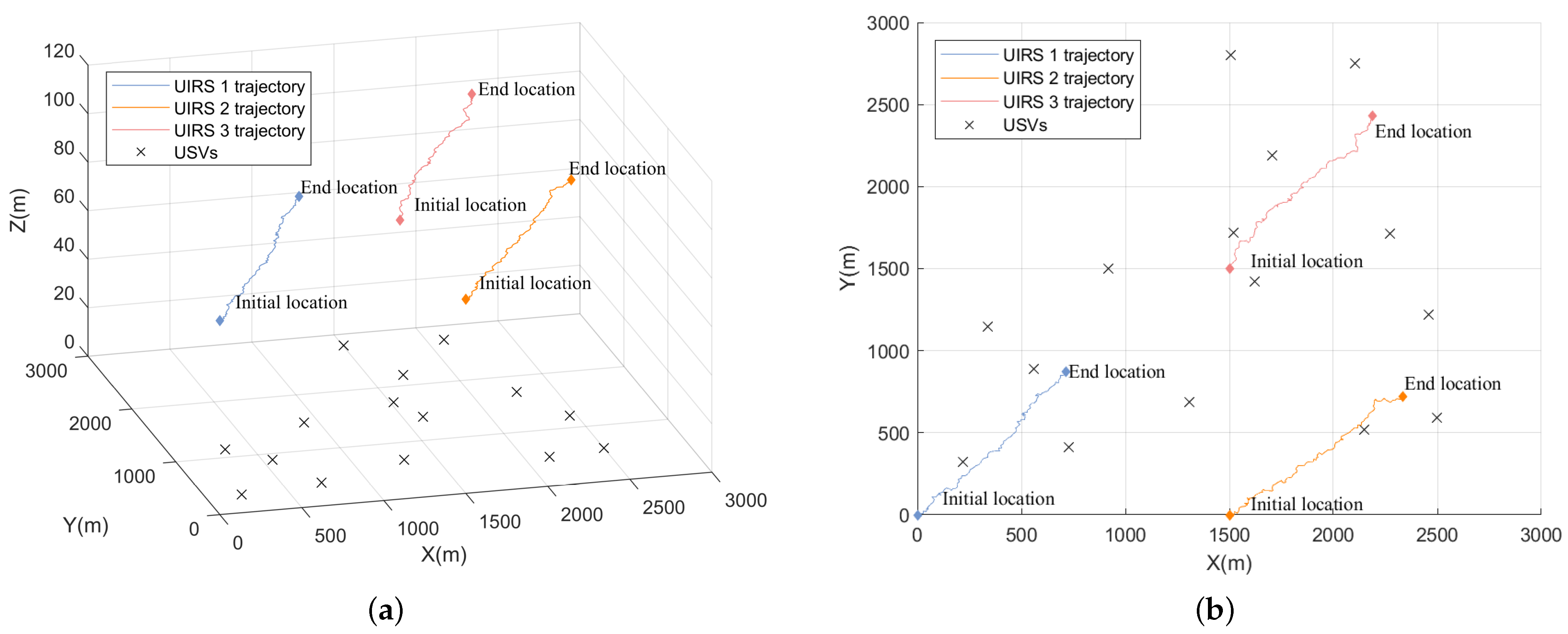
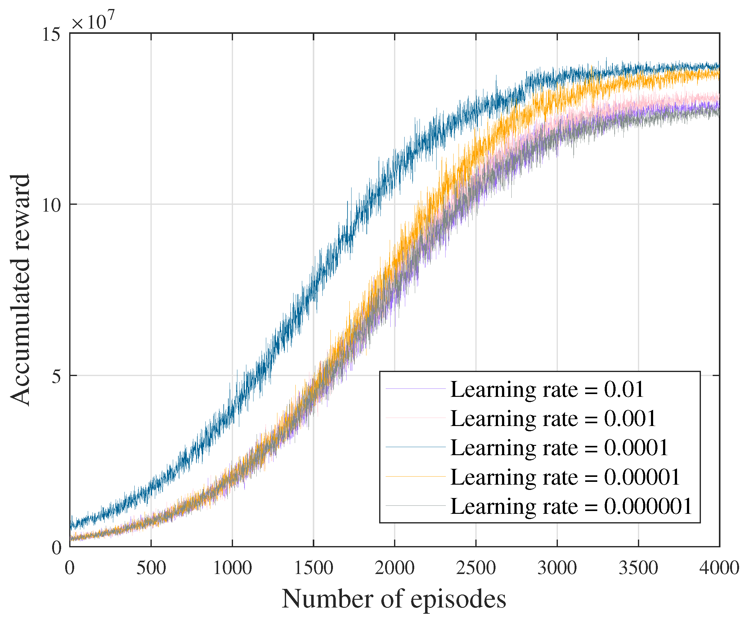
4. Numerical Results

In this section, we develop a simulator in Python to evaluate the performance of the proposed CO-MATD3 algorithm. The deep reinforcement learning algorithm based on MATD3 is implemented in PyTorch. In our simulations, we consider that 15 USVs are randomly distributed in an ocean area of 3000 m × 3000 m. For the rotary-wing UAV, we set U tip = 120 , d 0 = 0.6 , ρ = 1.225 , S 0 = 0.05 , A 0 = 0.503 , v = 4.3 , P 0 = 79.856 , P 1 = 88.628 , and P 2 = 11.46 [35,37,38]. The simulation parameters are listed in Table 1.
We implement four benchmarks for performance comparison as follows:
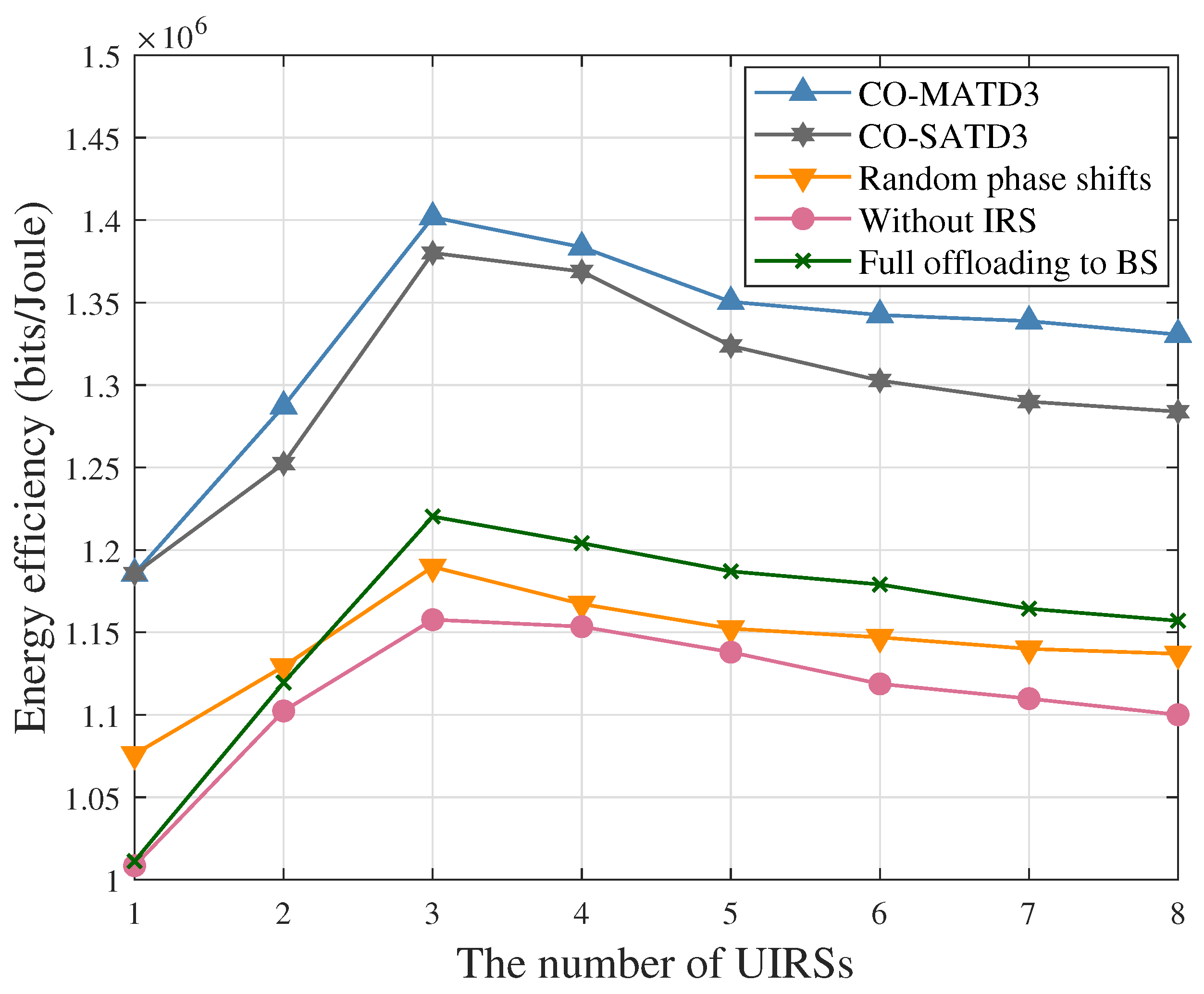
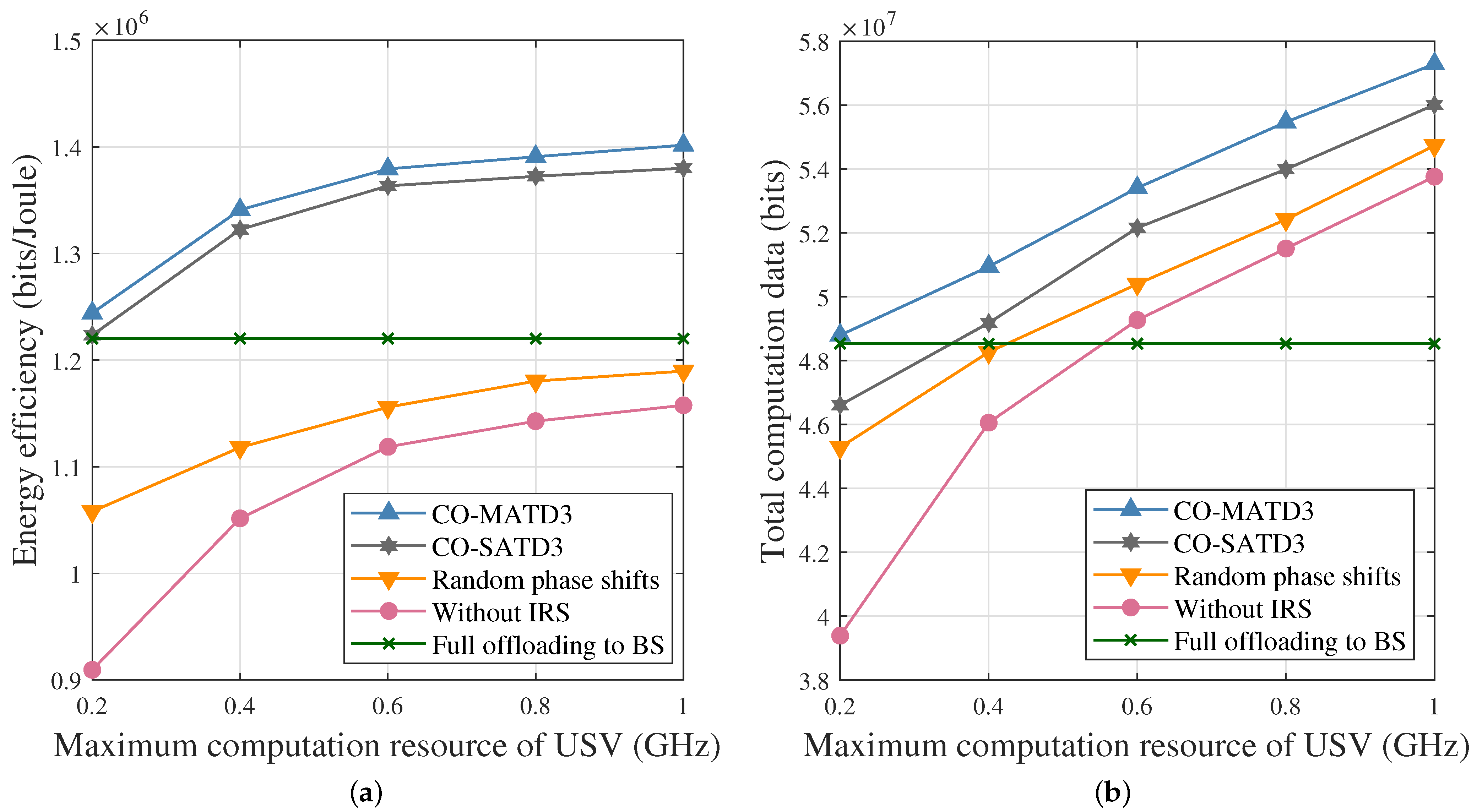
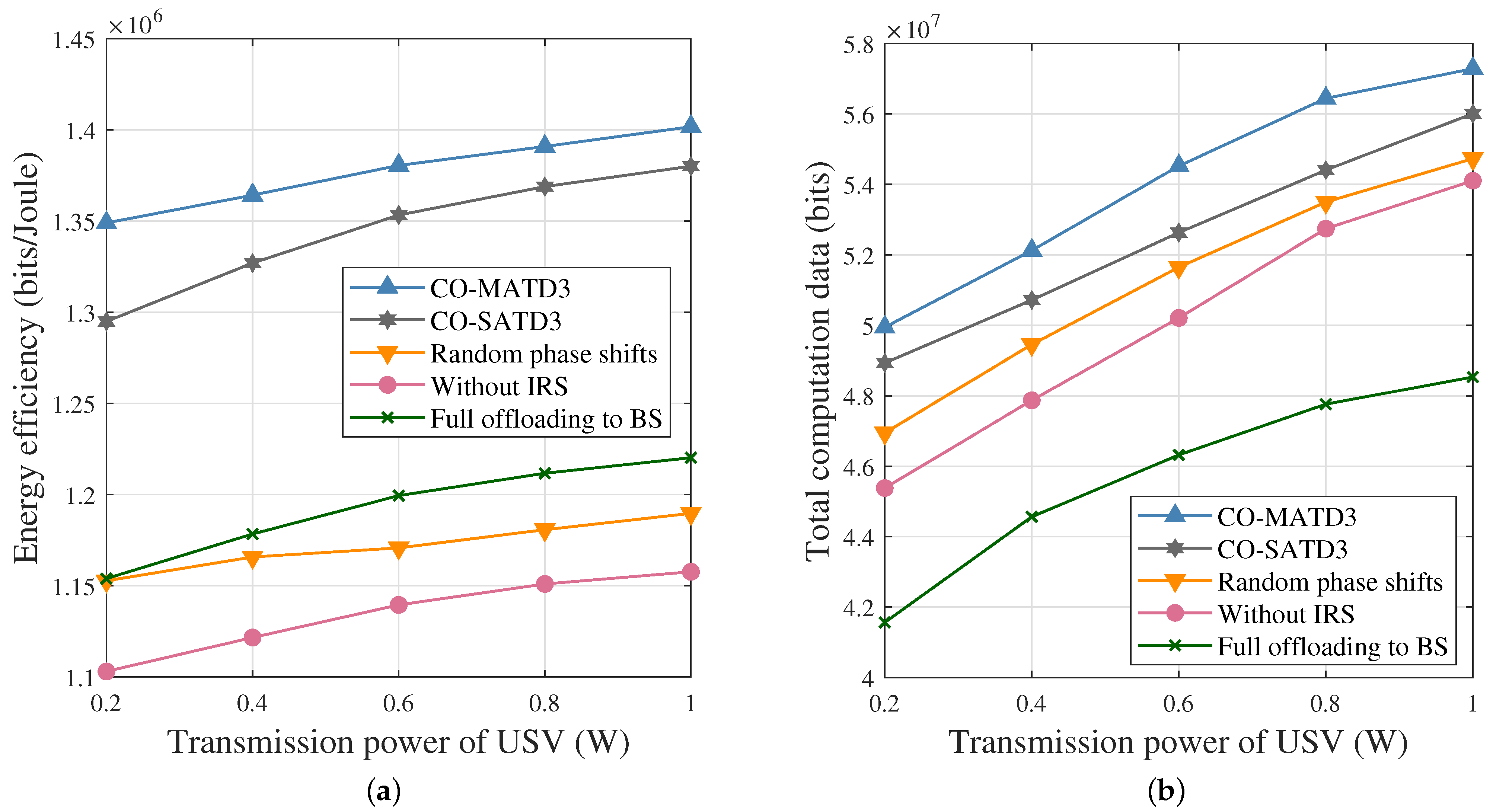
  • Convex Optimization and Single-Agent TD3 (CO-SATD3). In this scheme, the SATD3 algorithm aims to optimize the EEM-Outer problem, while the EEM-Inner problem is optimized by Section 3.1. For the SATD3 algorithm, the shore BS acts as the agent to centrally manage the state and action information of USVs and UIRSs.
  • Random phase shifts scheme. In this scheme, the phase shifts of the reflection elements are randomly selected in the constraint range.
  • Without IRS scheme. This scheme involves a multi-UAV-assisted marine vehicle system without an IRS, in which each UAV acts as a decode-and-forward relay node to achieve data transmission from USVs to the shore BS.
  • Full offloading to BS scheme. In this scheme, the computation tasks of USVs are fully offloaded to the shore BS for edge computing, while the USVs cannot process computation tasks locally.
Figure 3a and Figure 3b show the three UIRS trajectories in 3D and 2D obtained by the proposed CO-MATD3, respectively. It can be observed that three UIRSs increase the flight height, and the flight height of the UIRS 3 is slightly higher than the others, as shown in Figure 3a. This is because the high flight altitude can increase the LoS link probability and reduce path loss to improve the channel quality, especially when the UIRS 3 is far away from the BS. After being trained, the UIRSs have learned to collaborate with each other to provide wireless communication services for USVs. In addition, the UIRSs have the capability to identify areas with a concentration of USVs and move gradually to conserve energy consumption while improving the computation bits. It is worth noting that the initial locations of UIRSs are default locations, and the trajectories of UIRSs are not periodic because the deployment locations of UIRSs need to accommodate the number of UIRSs, distribution of USVs, and offloading workloads of USVs.
Figure 4 illustrates the impact of different learning rates on accumulated rewards obtained by our proposed CO-MATD3 when deep neural networks have three hidden layers with ( 512 , 256 , 128 ) neurons. Both the actor network’s learning rate ε n act and critic network’s learning rate ε n cri are set to 0.01 , 0.001 , 0.0001 , 0.00001 , and 0.000001 . The results show that when the learning rate is 0.0001 , the accumulated reward is higher than other learning rates.
The convergence performance comparison between CO-MATD3 and CO-SATD3 is shown in Figure 5 when N = 3 and M = 15 . It can be seen that the proposed CO-MATD3 algorithm requires about 3000 episodes to converge properly, while the CO-SATD3 algorithm requires about 4000 episodes to converge. In addition, the final accumulated reward of the CO-MATD3 is slightly higher than that of the CO-SATD3. The reason is that the RMTD scheme based on the CO-MATD3 algorithm can stimulate multiple agents to achieve a maximum reward, due to the fact that each agent shares its experience and learns other agents’ policies based on distributed training to maximize the accumulated reward. However, the neural network of the CO-SATD3 requires the concatenation state of the center agent to construct the global state information, which makes the optimization problem solved by the CO-SATD3 more challenging. Such an observation shows that the multi-agent deep reinforcement learning algorithm is an efficient and valuable solution to achieve faster convergence and better performance.
Figure 6 presents the energy efficiency performance of the proposed CO-MATD3 with that of the four benchmarks versus different numbers of UIRSs when M = 15 . It can be observed that in the optimization schemes with the UIRS assistance (i.e., CO-MATD3, CO-SATD3, random phase shifts, and full offloading to BS), as the number of UIRSs increases, the energy efficiency increases at first. It is worth emphasizing that the case of multiple UIRSs outperforms that of the single UIRS in terms of energy efficiency. Then, when the number of UIRSs exceeds three, the energy efficiency performance begins to decline. The reason is that as the number of UIRSs increases, the transmission rate improves, but the energy consumption of the UIRSs correspondingly increases significantly. In this context, the growth in energy consumption outweighs the increase in total computation bits, leading to a decline in computational efficiency. These findings emphasize the importance of an optimal number of UIRSs in achieving energy efficiency performance. Moreover, we can see that the superiority of the UIRS assistance scheme over the without IRS scheme, which can provide more effective communication and computation services. Note that the number of UIRSs represents the number of UAVs employed in the without IRS scheme. Notably, the benchmarks of random phase shifts and full offloading are worse than our proposed CO-MATD3. This is because poor channel conditions and unreasonable computation offloading inevitably waste communication and computation resources, resulting in low energy efficiency. The above results indicate that the assistance of multiple UIRSs, offloading design, and phase shift optimization have degrees of impact on energy efficiency.
Figure 7 presents the energy efficiency performance of the proposed CO-MATD3 with that of the four benchmarks versus different numbers of USVs when N = 3 . We can see that the proposed CO-MATD3 outperforms the CO-SATD3, random phase shifts, without IRS, and full offloading to BS, which demonstrates the effectiveness of our proposed CO-MATD3 in the optimization of resource management and trajectory optimization. According to the results from Figure 7, the performance of the IRS assistance schemes (i.e., CO-MATD3, CO-SATD3, random phase shifts, and full offloading to BS) is always better than the without IRS scheme, which indicates the employment of IRS can achieve better energy efficiency. In addition, the energy efficiency gap between the proposed CO-MATD3 and the full offloading scheme increases as the number of USVs increases, which demonstrates the advantages of collaborative local computation and computation offloading. Compared with the CO-SATD3, our proposed MATD3 can obtain better energy efficiency, especially for N > 15 USVs. The reason is that the CO-SATD3 algorithm with central training is much more complex due to the global state construction. Therefore, our proposed CO-MATD3 can better optimize multi-dimensional resources.
Figure 8 studies the impact of the maximum computation resources on the performance of the proposed CO-MATD3 with that of the four benchmarks when N = 3 and M = 15 . In Figure 8a, the graph reveals a trend in which energy efficiency improves when the computation resources increase from 0.2 GHz to 1 GHz, and the increase rate becomes much slower. Intuitively, the high computation resources of the USV can improve the local computation rate, which increases the total computation data, as shown in Figure 8b. However, the USV increases the computation resources to improve the local computation rate; it will undoubtedly consume more local computation energy consumption. In this context, although the maximum computation resources of the USV increase, the energy efficiency will not be notably varied when the computation resources are optimized to a certain value. To sum up, the optimization of the computation resources of the USV can effectively increase energy efficiency and total computation data.
Figure 9 studies the impact of the transmission power on the performance of the proposed CO-MATD3 with that of the four benchmarks when N = 3 and M = 15 . It is evident that the performance of all schemes is enhanced with the increased transmission power of the USV. Especially, we can see that the performance of the proposed CO-MATD3 outperforms benchmarks. As shown in Figure 9a, energy efficiency maintains an upward trend as the transmission power of USV increases. In Figure 9b, as the transmission power of USV increases, the total computation data increases, which can consume large energy consumption simultaneously. At this time, the increase in computation data is more than the consumed energy, and as a result, energy efficiency improves. However, the trend of improving energy efficiency is decreasing. This finding shows when the transmission power of the USV reaches the threshold, energy efficiency will not be notably increased. The reason is that our proposed scheme focuses on energy efficiency maximization rather than computation data maximization.
In this work, energy efficiency is not only affected by the UIRSs’ flight energy consumption but is also related to the communication and computation energy consumption, as well as the total computation bits, which is a complex optimization problem. According to Equation (15), the flight energy consumption is affected by the flying velocity and the length of the slot time. As mentioned in [39], the flight energy consumption reaches its minimum when the flying velocity is approximately 10.2 m/s during each equal length of slot time. In this work, we aim to improve computation efficiency by increasing computation bits while reducing energy consumption. Therefore, the UIRS is set to move in a straight path at a constant velocity of 10.2 m/s, which corresponds to the minimum flight energy consumption. This flight scheme is used as a baseline for comparison. Otherwise, we also choose the constant velocity scheme and random flight scheme as a comparison to analyze the UIRS mobility (including flight velocity and angle) impact on energy efficiency.
To evaluate the effectiveness of the UIRS mobility optimization, we use the five different UIRS mobility schemes, where “10 m/s”, “20 m/s”, and “30 m/s” indicate the UIRSs moving at a constant velocity with an optimized angle, “random” indicates the UIRSs moving at arbitrary velocities and angles, and “ 10.2 m/s” indicates the UIRSs moving in a straight flight at a constant velocity. We compare the impact of UIRS mobility on energy efficiency in Figure 10. It can be seen that our proposed scheme with an optimized velocity of the UIRS is better than the other five schemes in terms of energy efficiency. The reason is that our proposed scheme optimizes the velocities and angles of UIRSs according to the requirements of computation offloading to arrive at the optimal positions and obtain the satisfied communication links at each time slot, which ensures the high total computation bits and does not consume too much flight energy consumption. These simulation results demonstrate that the proposed solution can dynamically adjust the velocities and angles of UIRSs to achieve a better trade-off between computation bits and energy consumption.

5. Conclusions

In this paper, we have proposed a resource management and trajectory design scheme for multi-UIRS-assisted marine vehicle systems. Firstly, an energy efficiency maximization problem has been formulated by jointly optimizing the association relationships, computation resources, multi-UIRS phase shifts, and multi-UIRS trajectories. Then, the CO-MATD3 algorithm has been proposed to solve the challenging optimization problem. Specifically, the Dinkelbach method and relaxation method are applied to optimize the discrete variables in the inner layer, and learning-based MATD3 is employed to optimize the continuous variables in the outer layer. Finally, the numerical results have shown that the proposed CO-MATD3 can achieve outstanding overall performance in terms of training convergence and energy efficiency.

Author Contributions

Conceptualization, C.Z.; methodology, C.Z. and S.Q.; software, C.Z.; validation, C.Z. and B.L.; formal analysis, C.Z. and S.Q.; investigation, C.Z. and B.L.; resources, C.Z.; data curation, C.Z. and C.L.; writing—original draft preparation, C.Z.; writing—review and editing, C.Z., B.L., and C.L.; visualization, C.Z. and S.Q.; supervision, C.Z.; project administration, B.L.; funding acquisition, B.L. All authors have read and agreed to the published version of this manuscript.

Funding

This work was supported in part by the National Natural Science Foundation of China under Grants 62371085 and 51939001, and in part by the Fundamental Research Funds for the Central Universities under Grant 3132023514.

Institutional Review Board Statement

Not applicable.

Informed Consent Statement

Not applicable.

Data Availability Statement

The data are contained within the article.

Conflicts of Interest

The authors declare no conflicts of interest.

References

  1. Wei, T.; Feng, W.; Chen, Y.; Wang, C.X.; Ge, N.; Lu, J. Hybrid satellite-terrestrial communication networks for the maritime Internet of Things: Key technologies, opportunities, and challenges. IEEE Internet Things J. 2021, 8, 8910–8934. [Google Scholar] [CrossRef]
  2. Xu, W.; Gu, L. UAV Relay Energy Consumption Minimization in an MEC-Assisted Marine Data Collection System. J. Mar. Sci. Eng. 2023, 11, 2333. [Google Scholar] [CrossRef]
  3. Su, X.; Meng, L.; Huang, J. Intelligent Maritime Networking with Edge Services and Computing Capability. IEEE Trans. Veh. Technol. 2020, 69, 13606–13620. [Google Scholar] [CrossRef]
  4. Dai, M.; Luo, Z.; Wu, Y.; Qian, L.; Lin, B.; Su, Z. Incentive Oriented Two-Tier Task Offloading Scheme in Marine Edge Computing Networks: A Hybrid Stackelberg-Auction Game Approach. IEEE Trans. Wirel. Commun. 2023, 22, 8603–8619. [Google Scholar] [CrossRef]
  5. Jung, S.; Jeong, S.; Kang, J.; Kang, J. Marine IoT Systems with Space–Air–Sea Integrated Networks: Hybrid LEO and UAV Edge Computing. IEEE Internet Things J. 2023, 10, 20498–20510. [Google Scholar] [CrossRef]
  6. Yang, H.; Lin, K.; Xiao, L.; Zhao, Y.; Xiong, Z.; Han, Z. Energy Harvesting UAV-RIS-Assisted Maritime Communications Based on Deep Reinforcement Learning Against Jamming. IEEE Trans. Wirel. Commun. 2024, 23, 9854–9868. [Google Scholar] [CrossRef]
  7. Dai, M.; Dou, C.; Wu, Y.; Qian, L.; Lu, R.; Quek, T.Q.S. Multi-UAV Aided Multi-Access Edge Computing in Marine Communication Networks: A Joint System-Welfare and Energy-Efficient Design. IEEE Trans. Commun. 2024, 72, 5517–5531. [Google Scholar] [CrossRef]
  8. Cai, Y.; Wei, Z.; Hu, S.; Liu, C.; Ng, D.W.K.; Yuan, J. Resource Allocation and 3D Trajectory Design for Power-Efficient IRS-Assisted UAV-NOMA Communications. IEEE Trans. Wirel. Commun. 2022, 21, 10315–10334. [Google Scholar] [CrossRef]
  9. Wu, Q.; Zhang, R. Joint Active and Passive Beamforming Optimization for Intelligent Reflecting Surface Assisted SWIPT Under QoS Constraints. IEEE J. Sel. Areas Commun. 2020, 38, 1735–1748. [Google Scholar] [CrossRef]
  10. Wang, Y.; Fang, L.; Cai, S.; Lian, Z.; Su, Y.; Xie, Z. Low-Complexity Algorithm for Maximizing the Weighted Sum-Rate of Intelligent Reflecting Surface-Assisted Wireless Networks. IEEE Internet Things J. 2024, 11, 10490–10499. [Google Scholar] [CrossRef]
  11. Xu, W.; Gu, L. Energy-Efficient Resource Optimization for IRS-Assisted VLC-Enabled Offshore Communication System. J. Mar. Sci. Eng. 2024, 12, 772. [Google Scholar] [CrossRef]
  12. Wu, Q.; Zhang, R. Intelligent Reflecting Surface Enhanced Wireless Network via Joint Active and Passive Beamforming. IEEE Trans. Wirel. Commun. 2019, 18, 5394–5409. [Google Scholar] [CrossRef]
  13. Zhu, Y.; Mao, B.; Kato, N. A Dynamic Task Scheduling Strategy for Multi-Access Edge Computing in IRS-Aided Vehicular Networks. IEEE Trans. Emerg. Top. Comput. 2022, 10, 1761–1771. [Google Scholar] [CrossRef]
  14. Li, Z.; Chen, M.; Yang, Z.; Zhao, J.; Wang, Y.; Shi, J.; Huang, C. Energy Efficient Reconfigurable Intelligent Surface Enabled Mobile Edge Computing Networks with NOMA. IEEE Trans. Cogn. Commun. Netw. 2021, 7, 427–440. [Google Scholar] [CrossRef]
  15. Li, Y.; Wang, F.; Zhang, X.; Guo, S. IRS-Based MEC for Delay-Constrained QoS Over RF-Powered 6G Mobile Wireless Networks. IEEE Trans. Veh. Technol. 2023, 72, 8722–8737. [Google Scholar] [CrossRef]
  16. Chen, G.; Wu, Q.; Liu, R.; Wu, J.; Fang, C. IRS Aided MEC Systems with Binary Offloading: A Unified Framework for Dynamic IRS Beamforming. IEEE J. Sel. Areas Commun. 2023, 41, 349–365. [Google Scholar] [CrossRef]
  17. Yang, Y.; Gong, Y.; Wu, Y.C. Intelligent-Reflecting-Surface-Aided Mobile Edge Computing with Binary Offloading: Energy Minimization for IoT Devices. IEEE Internet Things J. 2022, 9, 12973–12983. [Google Scholar] [CrossRef]
  18. Aung, P.S.; Park, Y.M.; Tun, Y.K.; Han, Z.; Hong, C.S. Energy-Efficient Communication Networks via Multiple Aerial Reconfigurable Intelligent Surfaces: DRL and Optimization Approach. IEEE Trans. Veh. Technol. 2023, 73, 4277–4292. [Google Scholar] [CrossRef]
  19. Wang, C.; Chen, X.; An, J.; Xiong, Z.; Xing, C.; Zhao, N.; Niyato, D. Covert Communication Assisted by UAV-IRS. IEEE Trans. Commun. 2023, 71, 357–369. [Google Scholar] [CrossRef]
  20. Lu, H.; Zeng, Y.; Jin, S.; Zhang, R. Aerial Intelligent Reflecting Surface: Joint Placement and Passive Beamforming Design with 3D Beam Flattening. IEEE Trans. Wirel. Commun. 2021, 20, 4128–4143. [Google Scholar] [CrossRef]
  21. Truong, T.P.; Tuong, V.D.; Dao, N.N.; Cho, S. FlyReflect: Joint Flying IRS Trajectory and Phase Shift Design Using Deep Reinforcement Learning. IEEE Internet Things J. 2023, 10, 4605–4620. [Google Scholar] [CrossRef]
  22. Zhai, Z.; Dai, X.; Duo, B.; Wang, X.; Yuan, X. Energy-Efficient UAV-Mounted RIS Assisted Mobile Edge Computing. IEEE Wirel. Commun. Lett. 2022, 11, 2507–2511. [Google Scholar] [CrossRef]
  23. Ai, Q.; Qiao, X.; Liao, Y.; Yu, Q. Joint Optimization of USVs Communication and Computation Resource in IRS-Aided Wireless Inland Ship MEC Networks. IEEE Trans. Green Commun. Netw. 2022, 6, 1023–1036. [Google Scholar] [CrossRef]
  24. Li, Y.; Zhang, H.; Long, K.; Nallanathan, A. Exploring Sum Rate Maximization in UAV-Based Multi-IRS Networks: IRS Association, UAV Altitude, and Phase Shift Design. IEEE Trans. Commun. 2022, 70, 7764–7774. [Google Scholar] [CrossRef]
  25. Li, Z.; Hua, M.; Wang, Q.; Song, Q. Weighted Sum-Rate Maximization for Multi-IRS Aided Cooperative Transmission. IEEE Wirel. Commun. Lett. 2020, 9, 1620–1624. [Google Scholar] [CrossRef]
  26. Rafieifar, A.; Ahmadinejad, H.; Razavizadeh, S.M.; He, J. Secure Beamforming in Multi-User Multi-IRS Millimeter Wave Systems. IEEE Trans. Wirel. Commun. 2023, 22, 6140–6156. [Google Scholar] [CrossRef]
  27. Pan, H.; Liu, Y.; Sun, G.; Wang, P.; Yuen, C. Resource Scheduling for UAVs-Aided D2D Networks: A Multi-Objective Optimization Approach. IEEE Trans. Wirel. Commun. 2024, 23, 4691–4708. [Google Scholar] [CrossRef]
  28. Deng, X.; Zhao, J.; Kuang, Z.; Chen, X.; Guo, Q.; Tang, F. Computation Efficiency Maximization in Multi-UAV-Enabled Mobile Edge Computing Systems Based on 3D Deployment Optimization. IEEE Trans. Emerg. Top. Comput. 2023, 11, 778–790. [Google Scholar] [CrossRef]
  29. Duo, B.; He, M.; Wu, Q.; Zhang, Z. Joint Dual-UAV Trajectory and RIS Design for ARIS-Assisted Aerial Computing in IoT. IEEE Internet Things J. 2023, 10, 19584–19594. [Google Scholar] [CrossRef]
  30. Waraiet, A.; Cumanan, K.; Ding, Z.; Dobre, O.A. Robust Design for IRS-Assisted MISO-NOMA Systems: A DRL-Based Approach. IEEE Wirel. Commun. Lett. 2024, 13, 592–596. [Google Scholar] [CrossRef]
  31. Zhang, T.; Wen, H.; Jiang, Y.; Tang, J. Deep-Reinforcement-Learning-Based IRS for Cooperative Jamming Networks Under Edge Computing. IEEE Internet Things J. 2023, 10, 8996–9006. [Google Scholar] [CrossRef]
  32. Zhan, C.; Hu, H.; Liu, Z.; Wang, Z.; Mao, S. Multi-UAV-Enabled Mobile-Edge Computing for Time-Constrained IoT Applications. IEEE Internet Things J. 2021, 8, 15553–15567. [Google Scholar] [CrossRef]
  33. Qin, X.; Na, Z.; Wen, Z.; Wu, X. Relaying IRS-UAV Assisted Covert Communications in Uplink C-NOMA Network. IEEE Commun. Lett. 2024, 28, 2136–2140. [Google Scholar] [CrossRef]
  34. Yu, J.; Li, Y.; Liu, X.; Sun, B.; Wu, Y.; Hin-Kwok Tsang, D. IRS Assisted NOMA Aided Mobile Edge Computing with Queue Stability: Heterogeneous Multi-Agent Reinforcement Learning. IEEE Trans. Wirel. Commun. 2023, 22, 4296–4312. [Google Scholar] [CrossRef]
  35. Mei, H.; Yang, K.; Liu, Q.; Wang, K. 3D-Trajectory and Phase-Shift Design for RIS-Assisted UAV Systems Using Deep Reinforcement Learning. IEEE Trans. Veh. Technol. 2022, 71, 3020–3029. [Google Scholar] [CrossRef]
  36. Zhao, T.; Li, F.; He, L. DRL-Based Secure Aggregation and Resource Orchestration in MEC-Enabled Hierarchical Federated Learning. IEEE Internet Things J. 2023, 10, 17865–17880. [Google Scholar] [CrossRef]
  37. Zhang, R.; Pang, X.; Lu, W.; Zhao, N.; Chen, Y.; Niyato, D. Dual-UAV Enabled Secure Data Collection with Propulsion Limitation. IEEE Trans. Wirel. Commun. 2021, 20, 7445–7459. [Google Scholar] [CrossRef]
  38. Zeng, Y.; Xu, J.; Zhang, R. Energy Minimization for Wireless Communication with Rotary-Wing UAV. IEEE Trans. Wirel. Commun. 2019, 18, 2329–2345. [Google Scholar] [CrossRef]
  39. Pan, H.; Liu, Y.; Sun, G.; Fan, J.; Liang, S.; Yuen, C. Joint Power and 3D Trajectory Optimization for UAV-Enabled Wireless Powered Communication Networks with Obstacles. IEEE Trans. Commun. 2023, 71, 2364–2380. [Google Scholar] [CrossRef]
Figure 1. The multi-UIRS-assisted marine vehicle system model.
Jmse 12 01761 g001
Figure 2. Framework for the MATD3-based EEM-Outer algorithm.
Jmse 12 01761 g002
Figure 3. The multi-UIRS trajectories achieved by CO-MATD3. (a) The view of the 3D trajectory; (b) the view of the 2D trajectory.
Jmse 12 01761 g003
Figure 4. Accumulated reward convergence comparison for different learning rates.
Jmse 12 01761 g004
Figure 5. Convergence performance comparison between CO-MATD3 and CO-SATD3.
Jmse 12 01761 g005
Figure 6. Energy efficiency versus different numbers of UIRSs.
Jmse 12 01761 g006
Figure 7. Energy efficiency versus different numbers of USVs.
Jmse 12 01761 g007
Figure 8. The energy efficiency and total computation data versus the maximum computation resources of the USV. (a) Energy efficiency; (b) total computation data.
Jmse 12 01761 g008
Figure 9. The energy efficiency and total computation data versus the transmission power of the USV. (a) Energy efficiency; (b) total computation data.
Jmse 12 01761 g009
Figure 10. Energy efficiency comparison with different UIRS mobility schemes.
Jmse 12 01761 g010
Table 1. Simulation parameters.
ParameterValue
The number of reflecting elements on the UIRS n, K n 10
Time slot length, τ 1 s
Channel bandwidth, W1 MHz
Channel gain at the reference distance, ρ 0 60  dB
Noise power, σ 2 114  dBm
The Rician factor, ξ m , n , ξ n , 0 31.3 [6]
The antenna height of the USV m, H m 5 m
The antenna height of the shore BS, H 0 35 m
Transmission power of the USV m, p m 1 W
The maximum computation resources of the USV m, f m max 1 GHz
The CPU cycles required to process one bit of USV m, C m loc 1000 cycles/bit
The effective switched capacitance of the USV m, κ m 10 27
The power of each reflecting element on the UIRS n, p n , k 0.001  W [34]
Disclaimer/Publisher’s Note: The statements, opinions and data contained in all publications are solely those of the individual author(s) and contributor(s) and not of MDPI and/or the editor(s). MDPI and/or the editor(s) disclaim responsibility for any injury to people or property resulting from any ideas, methods, instructions or products referred to in the content.

