Article

Effect of Lateral Airflow on Initial HSI and Flame Behavior of Marine Fuel in a Ship Engine Room: Experiment and Analysis

1
College of Ocean Science and Engineering, Shanghai Maritime University, Shanghai 201306, China
2
Research Center for International Compliance of Distant-Water Fishery, Shanghai Ocean University, Shanghai 201306, China
*
Author to whom correspondence should be addressed.
J. Mar. Sci. Eng. 2024, 12(1), 5; https://doi.org/10.3390/jmse12010005
Submission received: 12 November 2023 / Revised: 8 December 2023 / Accepted: 13 December 2023 / Published: 19 December 2023
(This article belongs to the Section Marine Hazards)

Abstract

:
The flame behavior of engine fires, such as those caused by leaked fuel coming into contact with an ignition source, is significant in practical applications, where flame detection is used to minimize the damage of the attendant ship fire safety problem. In this work, the flame behavior of hot-surface ignition (HSI) under crossflow was studied, with a particular focus on the difference in lateral airflow velocities for HSI-driven flame deviations at the windward and leeward sides of a ship engine room; a problem such as this has not previously been quantified. Full-scale experiments were conducted in a ship engine room using marine diesel and hydraulic oil as the fuel, and by adopting lateral airflow with the velocities of 0 m/s, 1.0 m/s, 3.0 m/s, and 5.0 m/s, together with an HSI mechanism consisting of marine diesel and hydraulic oil coming into contact with elevated hot-surface temperatures. The results show that the effects of disturbing the combustible gaseous mixture for marine fuel HSI, at both the windward and leeward sides, strengthened as the airflow velocity increased. The HSI position of the leaked marine fuel in the engine room was strongly dependent on ventilation, while that under the airflow condition decreased with the increase in the hot-surface temperature. A model was proposed to characterize this difference on the basis of the HSI height, which was defined as the ratio of the height during the initial HSI to the stationary period. The results indicate that the scale of the flame gradually increased in the horizontal direction, which was significantly different from the result in the scenario without mechanical ventilation. The results also revealed that the fluctuation of hydraulic oil through the temperature field was significant and lasted for a long time under a low HSI temperature.

1. Introduction

While some ignitions start in areas that do not affect a vessel’s ability to move, an engine room fire may seriously restrict a vessel’s mobility. Moreover, an engine room fire also obviously places a ship filled with operators at a high risk of injury or even death [1]. The data show that more than 56% of ship engine room fires occur in the main and auxiliary engines or associated components. Fire development can be divided into five stages, namely, initial ignition, flame spread, intense combustion, combustion decay, and extinguishment [2]. The airflow distribution and ventilation intensity in a ship engine room are related to the initial ignition and flame development [3,4,5]. An ignition source is easily formed by certain types of machinery found in ship engine rooms that is prone to leaking marine fuel that comes into contact with a high-temperature hot surface. The hot-surface ignition (HSI) of these marine fuels, however, is inherently limited by their reliance on triggers, such as temperature, gas concentration, and smoke, which depend on molecular or heat transmission from the leaked fuel to the ignition source. Consequently, the hazards of HSI caused by leaking marine fuel in a ship engine room should not be neglected, and the mechanisms of the initial HSIs causing leaking marine fuel and subsequent flame behavior deserve much more attention.
Researchers have conducted numerous works and case studies on ship fires, whose accidental chain of events can be found in the recent literature. In ship accidents, the risk of fire in the main engine fuel system was found to be the highest, and marine fuel leaks from diesel supply tanks or heavy fuel oil tanks were found to be the main cause of ship fires [6,7]. Kang et al. presented a framework of a computational fire simulation during the early basic design phase of a ship [8], and it focused on how to arrange fire control options with minimal changes to existing ship design procedures, as well as being a reference for life cycle fire safety management. By using the fire dynamics simulator (FDS) numerical method, Wu et al. [9] introduced a probabilistic model to estimate fatalities in ship fire accidents. The limitation of probabilistic models and the derivation of available safe egress time (ASET) was discussed, which indicated the uncertainty of estimating ASET under different types of parameters and ship cabin structures. Indeed, a fire in a ship engine room is different from a regular cabin fire, and the former’s suppression is key to the safety structure of a ship. Wang et al. [10] carried out a series of experimental tests in a scaled ship engine room and found that the temperature gradient of a ship engine room fire increased with fire size. In the case of a fire accident on the ship Le Boreal [11], it was significant that the ship fire had neither a root cause nor a simple cause concerning the unsafe actions of engineers or even management. The fire accidents concentrated on ships over twenty years were investigated [12]. It was found that, when the temperature of a surface increased due to the operation of the engine combined with leaked fuel, fires became inevitable. Leaked fuel, such as marine diesel, coming into contact with a hot surface leads to a pool fire. This displays three stages, namely, the initial growth, stabilization, and decay of a ship engine room fire [13]. In ship engine room fires, the smoke layer descends faster than that of regular compartment fires. The smoke induced by ship engine room fires contaminates the air surrounding the flame, which affects the plume entrainment rate [14]. The smoke layer height is one of the important parameters in a ship engine room fire. It has been found that the height of the smoke layer in a ship engine room fire gradually increases with the gradual increase in the volume of mechanically supplied air [15]. When the flame spreads through the obstacles in a ship engine room fire, it merges above the obstacles [16]. This shows the competition between the flame height enhancement effect and the weakening impact. There are obvious differences between a ship and a building in structure, environment conditions, fire dimensions, etc., leading to the careful consideration of fire models [17]. In a ship engine room, a lot of pipelines are arranged, such as marine diesel oil, hydraulic oil, and lubricating oil pipelines. Once a pipe fails and marine fuel leaks on hot surfaces, a ship engine room fire tends to occur [18]. Zeinali et al. [19] conducted a scaled experiment to evaluate the containment of smoke and heat flux induced by ship fires using water mist curtains, which indicated that the probability of flame spread to sections behind a water mist curtain decreased due to its cooling effect [19]. Zhu et al. [20] improved the YOLOv7-tiny model that could enhance the detection of ship engine room fires. The results showed the [email protected] of the improved model increased by a value of 2.6%, and the detection speed increased by 10 fps. The ignition of combustible fuel that leaks onto hot machinery components is a major cause of ship engine room fires. All the ignition limit values due to the ignition source being a hot surface were obtained, and it was found that the thermal conductivity of the materials and properties had a further significant impact on temperature development [21]. In the case of reactants injected at room temperature [22], the hot-surface-enabled ignition of ethanol contents in an aqueous fuel stream was above 30 wt.%. Menon et al. [23] carried out an experiment to analyze the hot-surface ignition of n-hexane/air mixtures, and they found that the second-stage ignition event was caused primarily by the decomposition of hydrogen peroxide triggered at a temperature above 900 K. Shepherd’s group researched the dynamics of the HSI of premixed fuel–air, adopting a combined method of experiment and numerical simulation [24]. A reaction pathway analysis showed that HSI was essentially driven by a linear chain chemical process, revealing the influence of chemical mixture properties on HSI sensitivity [25,26]. Furthermore, it indicated that the non-uniformity, heterogeneous chemistry, and reaction of the hot-surface temperature could affect the HSI threshold, as well as the location of ignition [27]. Eckhoff examined the experimental data from the HSI of mixtures, clarifying the minimum ignition temperature (MIT) and auto-ignition temperature (AIT) [28]. The characteristic parameters, such as the MIT of the fuel, ignition delay time, and heating rates, are important factors for revealing the HSI mechanism [29]. Mohaddes et al. [30] conducted a liquid fuel spray experiment on a hot surface, and it indicated that the ignition delay was greatly reduced with the occurrence of a higher hot-surface temperature prior to the establishment of mixing structures. Leaking fuel may result in the formation of an evaporating fuel film on a hot surface and the rebound of the impinging spray due to the Leidenfrost effect [31,32]. It is worth noting that leaked fuel continued to combust when the ignition source and combustible substance were in the same environment of a ship engine room [33,34,35]. The containment and removal of fire-driven smoke can be achieved via leeward displacement ventilation, which is also used for other purposes in engine area semiconductor facilities [36]. Airflow is a significant factor of an engine room that can change the flame drag and flame tilt angle, and the flame drag length of a sidewall fire is larger than that of a centerline fire under low airflow velocities [37]. The tilt angle and flame length changed nonlinearly with different airflow velocities [38,39], which indicated that the correlation of the flame geometry of ship engine room fires under ventilation deserves further investigation. In a sealed ship engine room, the flame is mainly driven by the momentum of the airflow from the hatch, causing the flame to deflect towards the inner wall [40]. A ship engine room fire can be conceived as a compartment fire triggered by an inflow of ventilation [41]; hence, it is important to assess the fire dynamics in such geometries to better understand and control those fires.
The previous studies with ship engine room fires mainly focused on a burning flame by pool fires or smoke flow regularity from a lifted flame in a cabin room. As such, there are still limited systematic data on the HSI-driven flame behaviors of leaked marine fuel in lateral airflow due to either ignition characteristics or direct flame spread. When subject to airflow in a ship engine room, the critical airflow velocity for flame deviation from the windward side can be different from that from the leeward side. Until now, there has been no targeted work or experimental arrangement designed to investigate the differences in the initial HSI temperature, flame behavior, marine fuel type, thermal effect, and their relation to airflow velocity in a ship engine room. In this study, a full-scale experiment and a series of tests of the leaked marine fuel ignition process in a ship engine room were carried out. The initial HSI characteristics of marine diesel and hydraulic oil were observed, and their parameters were recorded using both graphics technology and thermometry under different ventilation conditions. The height of the occurrence of the marine fuel initial HSI with an elevated hot-surface temperature and strengthened lateral airflow in a ship engine room was measured, based on which a dynamic prediction model was developed. Meanwhile, the flame deviations of the marine fuel HSI under different ventilated conditions with hot-surface temperatures were compared with those of analytical dimensions. Additionally, the vertical temperature field of leaked marine fuel combustion above the hot surface was analyzed to assess the accuracy of the HSI delay time and location. This study attempts to provide a fundamental understanding of characterized phenomena involved in the thermal ignition of leaked marine fuels with lateral airflow regimes in an effort to improve ship fire safety.

2. Materials and Methods

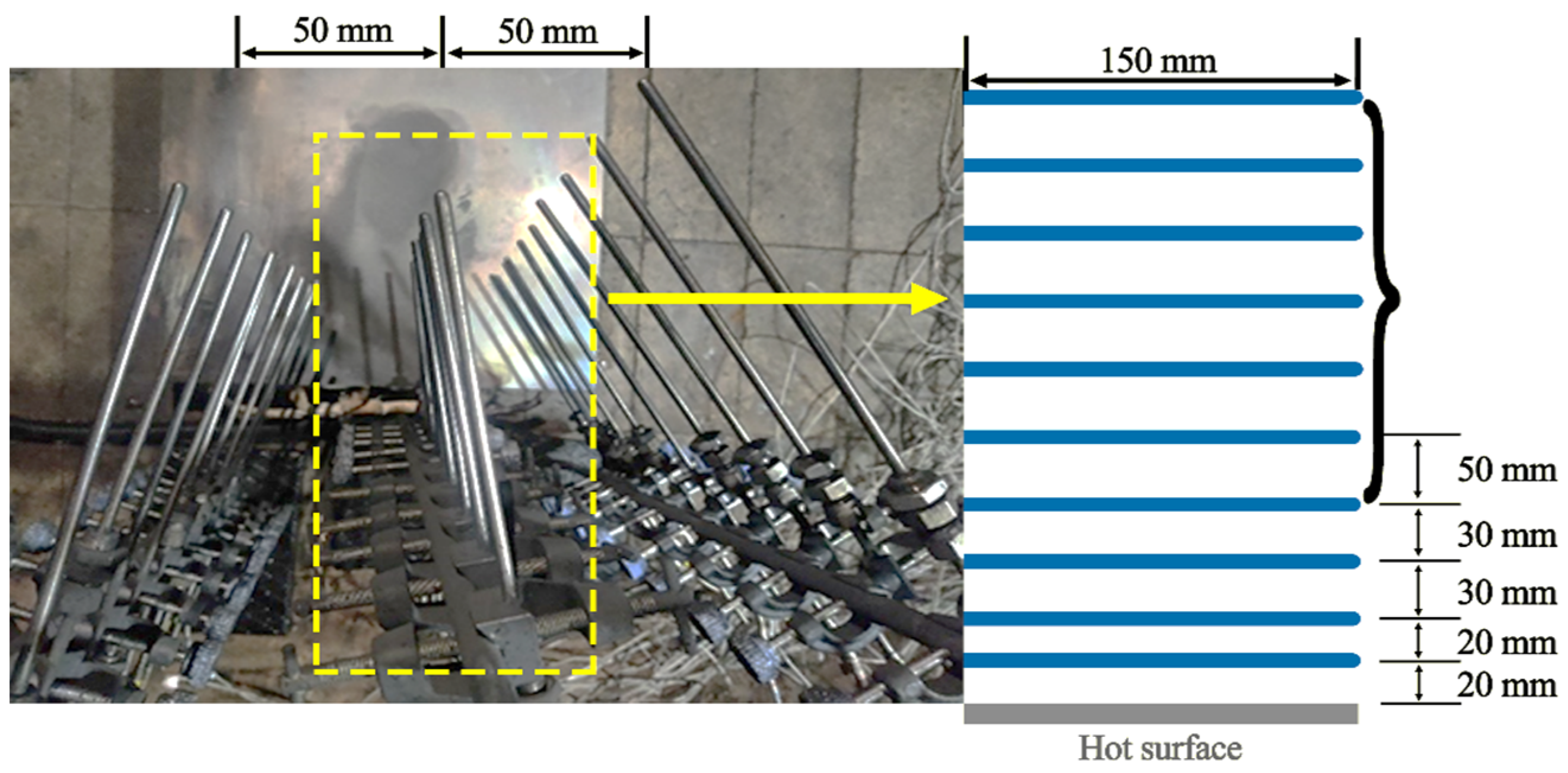
2.1. Experimental Apparatus

The engine room laboratory where this experiment is conducted is located in a ship front, and the experiment cabin is equipped with a fuel leakage control device, a typical high-temperature hot-surface platform, a data acquisition system, a ventilation system, and other equipment consistent with the real scene. The internal dimensions of the ship engine room laboratory are 6 m × 6 m × 2.7 m, as shown in Figure 1. The experimental side of the engine room has an air-tight cabin door. Its interior is arranged with related equipment and pipes, and its top has an exhaust outlet for exhausting air and connection with a fan. The top opening can also be kept in closed mode in order to simulate the top opening or closed condition of an actual ship engine room. The bottom has an air inlet that is installed to form a circulation with the top opening so that air circulation can be realized when smoke needs to be discharged after a single experiment. The ship engine room has an observation port and a data connection channel, and the operation of the equipment and the situation in the experiment cabin can be checked using a computer. In the experiment, a high-temperature hot surface is placed in the middle of the ground of the ship engine room, and its size is 0.4 m × 0.4 m. The maximum temperature of the hot-surface device can reach 750 °C, the experimental error is ±1 °C, and the display accuracy is 0.1 °C. The heating rods in the hot surface are uniformly arranged, which can achieve uniform temperature distribution above the surface. The hot surface can be directly connected to the computer for application. There are a total of three columns of K-type thermocouple bundles placed above the hot surface. The vertical ground height of the thermocouple bundles is 0.52 m, the transverse width is 0.15 m, and the spacing between adjacent columns is 0.05 m. With a length of 0.015 m and a diameter of 0.005 m, a thermocouple temperature probe is used to measure the spatial distribution of the vapor temperature above the hot surface when the leaked fuel evaporates and triggers ignition. Hygrometers and anemometers are installed inside the ship engine room to record the ambient temperature, humidity, and wind velocity above the hot surface. The anemometer can measure real-time airflow velocity within a range of 0.6~50 m/s, and it is equipped with a 16 mm impeller with an airflow velocity accuracy of 0.01 m/s. A high-speed camera, with a maximum frame rate of 1000 fps/s, is placed on a tripod in front of the hot-surface unit to record the instantaneous development of fuel ignition. Fan model DL6611182 can achieve multi-speed frequency conversion. In this experiment, three different lateral airflow conditions are set, with the velocities of 1.0 m/s, 3.0 m/s, and 5.0 m/s. As an industrial humidifier model, HQ-JS130H is used to keep the humidity constant in the experimental chamber. The water tank capacity is 50 L, the humidification volume is 1500 mL/h, and the error range is ±5%. The data acquisition module adopts a TP700 multi-channel data acquisition instrument. The instrument is equipped with 4 temperature acquisition modules, each of which has 8 channels, and a total of 32 channels can be connected for data reading. The signals of 30 thermocouples are converted into a digital signal, displayed on the screen of the recorder, and recorded at a time interval of 1.0 s. The anemometer, thermal imager, and high-speed camera are all located at a height of 0.2 m, ensuring that they are in the same plane as the HSI location. The real-time data of the ambient temperature, humidity, thermocouple temperature, and other parameters are then transmitted to a computer outside the ship engine room for storage through the data acquisition module. This experiment aims to facilitate the ignition process of different leaked marine fuels in contact with a hot surface, focusing on their ignition height, flame evolution law, flame plume, temperature distribution, etc.

2.2. Experimental Materials

In this experiment, marine diesel and hydraulic oil are selected, as they are the most common materials in a ship engine room. When the main engine is running, the temperatures of the outer shell surface and the leaked fuel itself remain high. If the pipe breaks and the fuel leaks onto the hot surface, a small amount of fuel may cause HSI and a subsequent fire. Based on the risk of such accidents, the amount of marine fuel used in this experiment is fixed at 10 mL. The marine fuel is divided into two types, one is distillate marine fuel, and the other is residual marine fuel. In this study, distillate marine fuel is selected for the accident scenario of a dual-fuel engine. Marine diesel is used in a dual-fuel engine mainly to provide power for the ship during navigation, and it can also be used for auxiliary ship engine power generation. The hydraulic oil system is composed of deck lifting machinery, a bow door, a bulkhead valve, a stern propeller, etc. Hydraulic oil is the hydraulic medium adopted in the system using liquid pressure energy, playing multiple roles of energy transfer, anti-wear, system lubrication, anti-corrosion, anti-rust, cooling, and so on. It is also commonly used in a special oil for transferring pressure (power) in a ship engine room, usually divided into ordinary hydraulic oil, anti-wear hydraulic oil, and low-freezing-point hydraulic oil. In this experiment, marine diesel and hydraulic oil L-HM46 are adopted. The characteristic parameters of the marine fuel used in the current experiment are presented in Table 1.

2.3. Experimental Procedure

In this experiment, there are related facilities and supporting pipeline equipment in the ship engine room, and multiple fans are used to change the ambient airflow velocities. A total of 60 experiments are carried out for each identified typical hot-surface temperature of an engine room. Among them, 30 tests are used to determine the ignition temperatures of marine diesel and hydraulic oil. The different lateral airflow conditions in a ship engine room may affect the ignition characteristics of leaked fuel on a hot surface. Therefore, four conditions of 0 m/s, 1.0 m/s, 3.0 m/s, and 5.0 m/s are examined in this experiment. It is worth noting that the lateral airflow velocity set in the experiment is the airflow velocity near the area of the high-speed operating equipment (i.e., with the potential to form an HSI source), rather than the velocity of the air supply outlet of the ship engine room. Then, the ventilation system in the ship engine room is turned on to maintain the whole process of ventilation. The air exhaust system in the ship engine room laboratory is restarted after each experimental testing is completed. The purpose of this is to prevent the subsequent experiment from being affected by the products generated after the HSI-based combustion or the marine fuel vapor without ignition. At the same time, once each group of experiments is completed, the hot surface and thermocouple are wiped with alcohol to prevent the residue of combustion products from affecting the accuracy and increasing the error of subsequent experiments. In this experiment, the control variable method is used to explore the HSI process and mechanism of the ship engine room under airflow conditions. The characterization parameters of a typical HSI source in a ship engine room are tested, including the HSI height, flame spread, and temperature distribution. According to the requirement of image acquisition, the resolution of the high-speed camera is 920 × 1080. By extracting the video frame by frame, an instantaneous image of the leaked marine fuel touching the hot surface is captured. With the temperature being measured by the thermocouple beam, the HSI height and other data are calculated synthetically. The humidity in the ship engine room is nearly 63%, while the initial ambient temperature is 310 K. The typical hot-surface temperature in the ship engine room does not change when the experiment is undertaken. Notably, all experiments are carried out under the same experimental conditions, except for the controlled airflow velocities. In this experiment, three thermocouple beams located above the hot surface are set up to collect temperature data at different heights. The transverse distance between the measuring tips of the three beam thermocouples is 5 mm. After the marine fuel spontaneously ignites above the hot surface, the flame quickly descends into the stable combustion stage. In order to measure the center temperature of the flame, a non-equidistant arrangement is adopted for each thermocouple beam. Among them, the vertical distance between the bottom thermocouple and the hot surface is 20 mm. The distance between the first and the second is 20 mm; the distance between the second, third, and fourth thermocouples is 30 mm; and the adjacent distance between the fourth and tenth branches is 50 mm. The arrangement of the thermocouples in this experiment can be seen in Figure 2.

2.4. Current Limitations and Assumptions of Experiment

In the current work, there are some known issues and inherent limitations associated with the representation of the experimental arrangement in the ship engine room laboratory, and they need to be illustrated in detail.
  • Some experiment equipment is arranged in the ship engine room laboratory in a manner that is more consistent with a real ship engine room. The aim is to restore, as much as possible, the operation and accident scene of a ship engine room in which leaked marine fuel is ignited due to contact with a high-temperature source on the equipment surface. However, other equipment set in the experiment does not directly start running. This may have an influence on the HSI temperature and delay time in terms of the thermal feedback in the ship engine room. This is where the prediction model should be further modified after data collection from thermal feedback in future research.
  • According to the accident scenarios of different marine fuels and airflow velocities in a ship engine room, the interval temperature of the hot surface is selected to be 5 °C. This is mainly due to the limitations in adjusting the temperature range in the high-temperature hot-surface simulator developed in the current experiment. The next step should be to improve the hot-surface simulator so that the heating interval can reach 1 °C or even 0.5 °C, thus promoting the accuracy of prediction models involved in examining HSI-driven flame behavior.
  • Finally, the influence of ship sloshing is not taken into account in the HSI process of the leaked marine fuel in the ship engine room. It is one of the key problems that deserve more attention in future research. Since ships are affected by wind and waves under different conditions when docking or sailing, the ship sloshing period and amplitude are inconsistent. Future research requires more experimental tests to combine sloshing factors with the HSI process and flame behavior. Making the dimensions covered by prediction models more comprehensive and applicable to a wider range of ship fire scenarios is yet to be achieved.

3. Results and Discussion

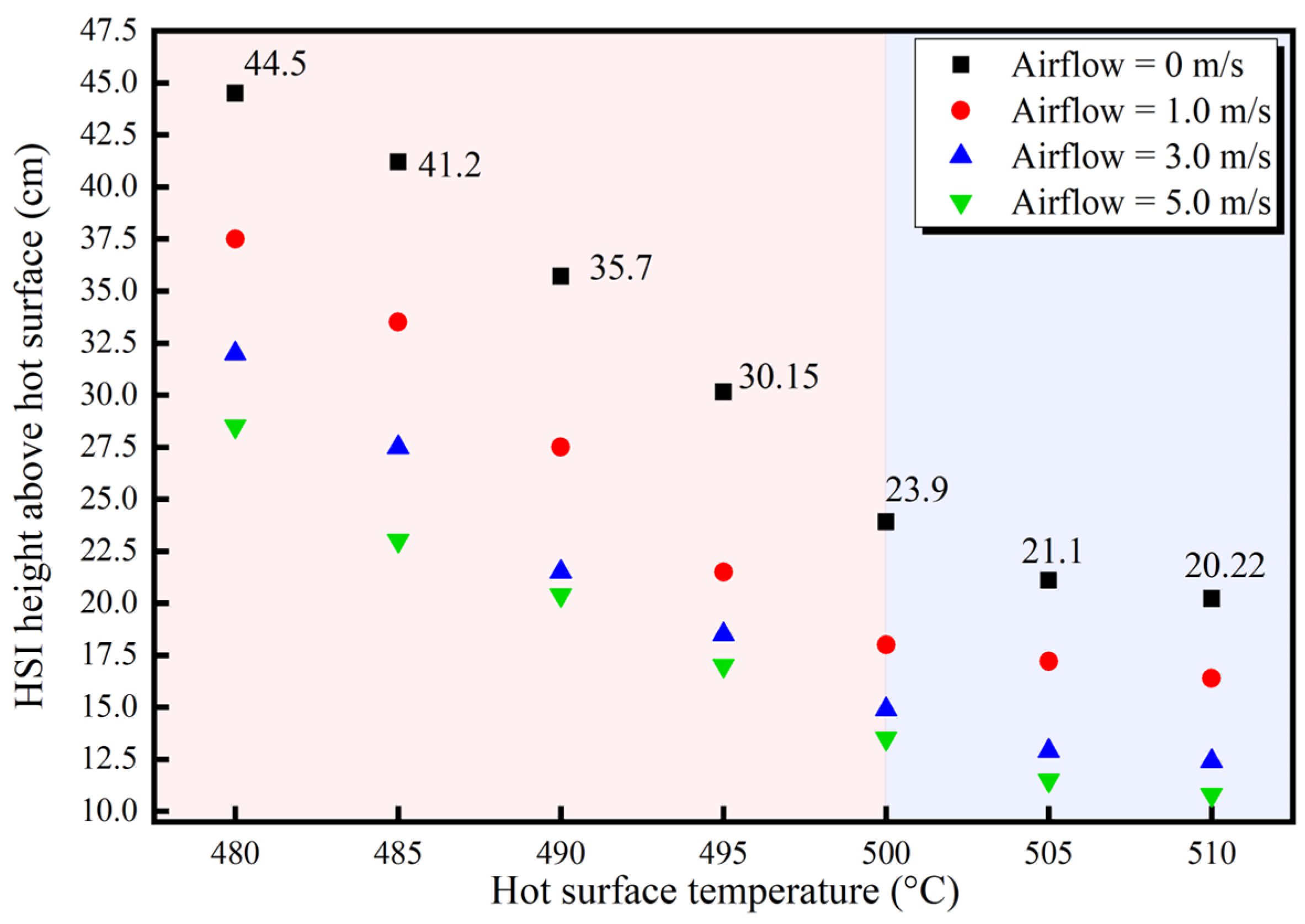
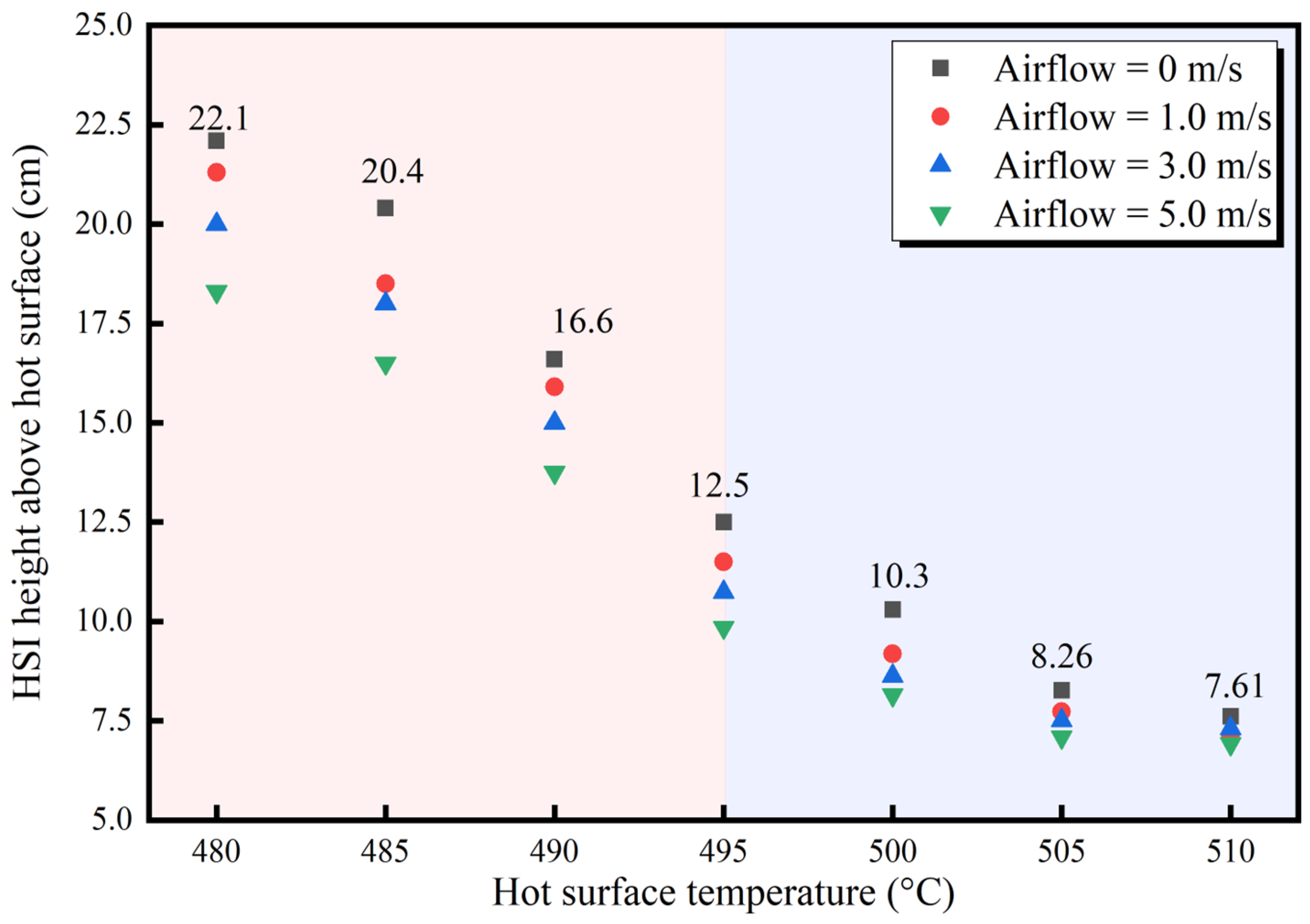
3.1. HSI Characteristics of Marine Fuel under Lateral Airflow in Ship Engine Room

Under different boiling modes, heat transfers on a hot surface are significantly different. The boiling heat transfer coefficient can be obtained using Equation (1). The total heat transfer coefficient of nuclear boiling ranges from 569 W/m2⋅K to 17,079 W/m2⋅K, and the total heat transfer coefficient of the transition boiling region ranges between 114 W/m2⋅K and 228 W/m2⋅K [42].
h = q · A 1 T w T sat
where A is the surface cross-sectional area, m; q is the heat flux in the HSI process, w/m2; Tw is the typical hot-surface temperature, K; and Tsat is the saturation temperature of the marine fuel, K.
The stage of nuclear boiling includes bubbles forming, growing, and exiting the surface. The motion agitates the liquid near the hot surface and produces a high heat transfer coefficient, which is indicated using Equation (2).
h n = h n , max T w   T sat T w   T sat max 2
where hn is the nuclear boiling heat transfer coefficient, W/m2∙K.
Assuming (Tw  Tsat)min = 0.3(Tw  Tsat)max, the maximum heat flux at the nuclear boiling state can be obtained using Equation (3).
q · A n , max 1 = 143 · H fg ρ L 0.6 ρ v 0.4
where Hfg is the latent heat of vaporization, J/(kg∙K); ρL is the liquid fuel density, kg/m3; and ρv is the fuel vapor density, kg/m3.
In the stage of transition boiling, the vapor produced at the surface separates the liquid from the surface. The state begins at a specific value of the wall temperature above the saturation temperature.
T w T sat min = 0.127 H fg ρ v k vf σ ρ L 1 2 g μ vf ρ L 1 3
where g is the acceleration of gravity, m/s2; kvf is the heat conductivity of the vapor in the film, W/(m·K); σ is the surface tension of the liquid, mN/m; and μvf is the viscosity of the vapor in the film between the wall and the liquid, Pa∙s.
The heat transfer coefficient hF in the above-mentioned state can be given using the following Equation (5) [43,44]:
h F   = 0.425   k vf 3 H fg ρ v ρ L 3 2 g T w T sat μ vf σ 1 2 1 4
Further, the fuel evaporation rate can be expressed by Equation (6), as shown in the following:
m F   = h F c p , g - 1 A In   b + 1
where mF is the fuel evaporation rate, gm/s; hF is the heat transfer coefficient of transition boiling, W/m2∙K; and B is the mass transfer number, whose expression is shown in Equation (7).
b = h fg 1 · c p , g · T w T b
Ignition height refers to the height difference between the position of the marine fuel at the initial ignition moment and the plane where the leaked fuel is located. Figure 3 shows the ignition process of marine diesel after coming into contact with a high-temperature hot surface. In the ignition process of marine diesel, a blue fire core forms in the cloud of the high-temperature diesel vapor above the hot surface, and then it rapidly spreads leeward until it ignites the marine fuel below. In this experiment, the ignition height is the height of the fire core in the first frame picture at the moment when the HSI phenomenon occurs. The specific ignition height data are obtained by combining the height of the fixed thermocouple with the captured images. This work shows that the marine fuel is in the nuclear boiling mode at the HSI temperature of the leaking fuel. The evaporation rates of the nuclear boiling and transitional boiling modes can be calculated theoretically using the above equations. According to the results, the heat transfer of nuclear boiling is usually much greater than that of transitional boiling. In a ship engine room, after the leaked marine fuel comes into contact with a high-temperature hot surface, four main stages occur as the hot-surface temperature increases. These stages are the natural convection heat transfer stage, nuclear boiling stage, transition boiling stage, and stable membrane boiling stage. In the natural convection stage, the whole system is in the state of single-phase convection heat transfer, with a small number of bubble cores appearing on the hot surface. The reason for this phenomenon is that the hot surface is not completely smooth due to the high temperature, and many tiny cavities contain gas. These tiny amounts of air form the initial bubble nucleus. At this time, the heat flux and heat transfer coefficient are one order of magnitude smaller than those of the two-phase heat transfer mode. The bubble core is produced only at a temperature slightly above the boiling point. With the rise of the hot-surface temperature, the heat absorbed by the marine fuel increases, and the number of bubble cores generated by the contact point between the leaking marine fuel and the hot surface also increases. The formation of bubbles and their movement inside the liquid intensify the turbulence inside the liquid. The heat flux and heat transfer coefficient are greatly increased. Furthermore, the heat transfer performance is obviously enhanced, reaching the nuclear boiling stage at this time. The contact area between the marine fuel and hot surface increases, and the wall is moistened by liquid. Meanwhile, the heat conduction rate reaches the maximum, and a large amount of combustible high-temperature vapor gathers above the leaked fuel. If the temperature of the combustible gas mixture formed after the mixing of this vapor and the air is still high enough, HSI behavior may occur. If no ignition occurs, as the hot-surface temperature continues to rise, on the one hand, the rate of bubble generation will accelerate. The speed of bubble escape is less than the rate of bubble generation, forming a string of bubble columns. On the other hand, as more bubbles are produced, columns of bubbles from nearby formation points will fuse close to the surface. When the heat flow from the surface reaches a critical value, a large number of bubble columns converge and fuse very close to the hot surface. As a result, a thin vapor film is formed, reaching the film boiling stage. In film boiling, there is a thin vapor film on the hot surface, above which bubbles are formed from a fixed position. The solid surface is surrounded by the vapor film without direct contact with the liquid, and the whole gas film breaks away from the interface to form a boiling film. At this time, the interfacial heat transfer suddenly drops, producing a huge temperature difference between the hot surface and the leaked marine fuel. As less dense vapor accumulates beneath the denser liquid, the liquid–gas interface is extremely unstable, and small disturbances can cause large fluctuations. At regular intervals across the film, this interface briefly breaks up to form a bubble.
Figure 3 shows the ignition process of the marine diesel on the hot surface in the ship engine room. Among the panels, Figure 3a shows the HSI behavior of the leaked fuel when the mechanical ventilation system is closed in the ship engine room. It can be seen that the rapid phase transition of the liquid occurs in the early stage of the marine diesel leaking towards the hot surface. As the hot-surface temperature rises to 480 °C, the marine diesel is almost in a constant state of film boiling. A very thin gas-phase interface is formed between the marine diesel and the hot surface, and the mode of heat transfer from the hot surface to liquid starts to change. Marine diesel is mainly composed of C12~C23 alkane, which belongs to a multi-component mixture [45,46]. When the marine diesel leaks and comes into contact with the hot surface at a time lapse of 3000.0 ms, a large amount of white smoke and mixtures are produced. The evaporation product of the marine diesel on the hot surface is fully mixed with the air in the ship engine room, and it basically forms a stable flammable mixture in the vertical space. At this time, the continuous heat transfer of the hot surface to the liquid surface is coupled with the thermal feedback effect around the ship engine room. When the marine diesel leaks for 4216.66 ms, the initial HSI behavior at high temperatures occurs instantaneously. In the images collected from the high-speed camera, it can be clearly observed that the initial HSI occurs at a higher position above the hot surface. The distance between the ignition height and the leaked marine diesel is closely related to the hot-surface temperature and environmental factors. The initial HSI forms a fire core in the air above the hot surface, after which the fire core gradually increases in size and produces a bright flame, as shown in Figure 3a. Figure 3b–d present the HSI process of leaked hot marine diesel when the ventilated velocities in the engine room are 1.0 m/s, 3.0 m/s, and 5.0 m/s, respectively. As the mechanical ventilation in the ship engine room increases, the ignition height of the leaked marine diesel on the hot surface shows a downward trend. The analysis indicates that the main factor of this phenomenon lies in the influence and restriction of the airflow in the ship engine room. The high-temperature hot surface formed by equipment operation has a thermal radiation effect on the air in the vertical space when its temperature rises. While the hot air flows upward, the surrounding cold air fills below, forming an upward air convection. When the airflow velocity is limited, the marine diesel comes into contact with the vapor generated by the hot surface to form a vertical upward plume, and the superimposed upward trend of the heated airflow makes the HSI behavior occur in the space above the liquid level. When the airflow rate in the ship engine room gradually increases, the airflow impacts the hot air and disturbs the evaporation and air mixture of the marine diesel, resulting in a reduction in its upward kinetic energy. The vapor/air mixture gradually accumulates in the vertical space closer to the hot surface, and the HSI height also decreases. The results show that, within a certain range of ventilation intensity, the higher the airflow velocity, the more obvious the disturbance effect on the combustible gas mixture, and the HSI height will decrease after losing part of the rising kinetic energy.
Figure 4 shows the ignition process of marine hydraulic oil after coming into contact with the high-temperature hot surface in the ship engine room. Among the panels, Figure 4a presents the HSI behavior of the leaked hydraulic oil when the mechanical ventilation system is turned off in the ship engine room. The properties of hydraulic oil are significantly different from those of other marine fuels, leading to a completely different evaporation process after coming into contact with a hot surface. When hydraulic oil happens to come into contact with a hot surface, the change in oil flow is not obvious. The spreading area of leaked hydraulic oil on a hot surface may be attributed to surface tension and viscosity. In this experiment, it is estimated via rough measurements that the three phases of hydraulic oil have obviously different surface tensions. Hydraulic oil is concentrated in the center area of the hot surface, and the gas phase generated is in a vertical spreading state. The gaseous medium produced by the hydraulic oil has a small spreading area in the vertical space. The air in the ship engine room is moved from the bottom to the top, and this is beneficial for the transportation of the hydraulic oil’s evaporated gas components. The initial HSI behavior finally occurs when the hydraulic oil comes into contact with the hot surface at 5574.98 ms. The ignition times of the hydraulic oil and marine diesel show an obvious difference. The initial core of the ignited hydraulic oil on the hot surface shows a blue light, which indicates that the combustible gaseous medium is fully mixed with the airflow, and the highest temperature occurs at the fire core. The HSI of the marine fuel in the ship engine room is the result of many factors. The high-temperature hot-surface convective heat transfers to the combustible mixed vapor formed by the hydraulic oil, and the environment has a thermal feedback effect on the hydraulic oil. When the initial hot-surface temperature is high, the leaked hydraulic oil immediately forms a relatively rapid evaporation mechanism after coming into contact with the hot surface, and the ignition conditions can be reached in a short time. If the hot-surface temperature is further increased, the location of HSI can be determined by collecting images from the high-speed camera after the hydraulic oil comes into contact with the hot surface. This is due to the boiling phenomenon occurring in a very short time after the hydraulic oil comes into contact with the hot surface. The flammable gas that undergoes a phase transition is ignited almost instantaneously. If the initial temperature of the hot surface is lower, it will take a longer time to reach the chemical reaction conditions that eventually trigger ignition, and the ignition delay time required to reach HSI increases. Over a relatively long period of time, more vapor-phase products are produced via the evaporation of the hydraulic oil on the hot surface. Compared with the marine diesel, the vapor-phase products formed by the heating of the hydraulic oil accumulate in the vertical space closer to the hot surface. As a result, a lower ignition height can be observed above the hot surface of the leaked hydraulic oil, as shown in Figure 4a. Figure 4b–d reveal the HSI process of the hydraulic oil under mechanical ventilation in the ship engine room. Figure 4b shows the HSI behavior of the hydraulic oil when the ventilation velocity in the ship engine room is 1.0 m/s. It can be seen that the airflow movement has a certain influence on the vertical spread of the hydraulic oil vapor/air mixture. The shape of the combustible mixed vapor cloud is shifted. When the hydraulic oil vapor/air mixture is initially ignited above the hot surface, the initial fire core appears to be closer to the hot surface than in the no-wind scenario. At the same time, under mechanical ventilation, the HSI height of the leaked hydraulic oil decreases. Figure 4c,d show the HSI characteristics of the hydraulic oil in the scenario where the ventilated velocities in the ship engine room rise to 3.0 m/s and 5.0 m/s, respectively. With the increase in airflow velocities, the ignition delay times of the HSI of the hydraulic oil increase significantly. Compared with the scenario without mechanical ventilation, when the ventilated velocity reaches 5.0 m/s, the HSI delay time of the hydraulic oil increases from 5574.98 ms to 11,516.65 ms. At the same time, with the increase in the ventilation intensity in the ship engine room, it can be observed that the ignition height of the hydraulic oil above the hot surface gradually displays a downward trend. In addition, by examining the experimental surface, it is found that, after the airflow condition is enhanced to a certain critical value, the HSI height of the leaked hydraulic oil no longer reduces further but tends to trigger ignition in a more stable area.
Figure 5 displays the changes in the HSI heights of the leaked marine fuels under different ventilation conditions. Among the panels, Figure 5 shows the changes in the HSI height of the marine diesel with the increase in the hot-surface temperature. The HSI height change of the leaked marine diesel in the ship engine room can be divided into two different stages. In the first stage, the HSI height of the marine diesel presents a significant decreasing trend with the increase in the hot-surface temperature. When the ventilated velocity in the ship engine room is 1.0 m/s, the HSI height is approximately 0.375 m as the hot-surface temperature rises to 480 °C. With the increase in the ventilation velocity to 3.0 m/s, the HSI height of the marine diesel decreases to 0.319 m at the same hot-surface temperature. After the ventilation velocity in the ship engine room further increases to 5.0 m/s, the HSI height of the diesel oil drops to 0.284 m. This enhanced mechanical ventilation in the ship engine room facilitates the mixing of the marine diesel vapor with the air to form an initial fire core closer to the ignition source. The continuous rise in the hot-surface temperature also promotes the transition of the boiling mode on the hot surface of the leaked marine diesel. The boiling mode of the marine diesel gradually changes from convective heat transfer to nuclear boiling, and the heat transfer of the leaked marine diesel increases rapidly with the increase in the hot-surface temperature. As a result, the evaporation rate of the marine diesel rises, forming a large combustible mixture concentration at a lower vertical position. In the scenario where the ventilation velocity in the engine room is 5.0 m/s, when the hot-surface temperature rises from the initial setting of 480 °C to 495 °C, the ignition height of the marine diesel oil decreases from 0.284 m to 0.171 m. The leakage of the marine diesel in this process is mainly caused by nuclear boiling and gradually reaches transition boiling, showing a large heat exchange between the marine diesel and the high-temperature hot surface. When the hot-surface temperature continues to rise to 500 °C, the HSI height of the marine diesel gradually and stably decreases. In the scenario where the ventilation velocity of the engine room is 5.0 m/s, the HSI height of the marine diesel drops from 0.134 m to 0.108 m when the hot-surface temperature rises from 500 °C to 510 °C. At this time, it reaches the second stage and the stable period when the HSI height of the marine diesel changes. The high temperature of the hot surface itself can provide a lot of heat within a short time, so the ignition behavior occurs in the area closer to the hot surface. As the hot-surface temperature continues to rise, the HSI height of the marine diesel no longer fluctuates greatly but basically maintains an area of nearly 0.10 m from the hot surface. According to the experimental data, there is a fitting relationship between the HSI height of the marine diesel and the hot-surface temperature, as shown in Equation (8). The R2 of this fitting curve is 0.931, which can be used to predict the initial HSI position of marine diesel under different ventilation conditions of a ship engine room.
H = H max + T m 0.0716 π · T s exp ln T s T min 2 46.875 H min
where Hmax is the HSI height during the initial ignition, m; Tm is the average change in the temperature of the hot surface, °C; Ts is the hot-surface temperature, °C; Tmin is the initial temperature of the hot surface, °C; and Hmin is the HSI height of the marine diesel during the stationary period, m.
Figure 6 shows the variation in the HSI heights of the marine hydraulic oil with elevated hot-surface temperatures. In the figure, a total of four sets of experimental data are derived from the scenarios of the ship engine room with no mechanical ventilation and different ventilated velocities. Through experimental observation, it can be found that the initial ignition position of the hydraulic oil is closer to the hot surface. This is closely associated with the properties of the hydraulic oil itself. In Figure 6, the HSI height of the hydraulic oil changes obviously, while the ignition height of the hydraulic oil gradually decreases with the increase in the hot-surface temperature in a windless environment. At the same time, the HSI height of the airflow velocity of the three kinds of ship engine rooms indicates a similar law with the temperature rise of the hot surface. When the hot-surface temperature of the ship engine room increases from 480 °C to 495 °C, the boiling mode of the hydraulic oil gradually changes from film evaporation to nuclear boiling. With the increase in the hot-surface temperature, the heat transfer rate and the evaporation rate of the hydraulic oil both increase. As a result, the concentration of the combustible mixture near the hot surface quickly reaches HSI conditions. In the scenario where the ventilation velocity in the ship engine room is 1.0 m/s, the ignition height of the hydraulic oil is about 0.213 m at a hot-surface temperature of 480 °C. In the same engine room environment, when the hydraulic oil leaks onto a surface with a temperature of 495 °C, its HSI height drops to 0.116 m. If the temperature of the hot surface further increases, the HSI height of the hydraulic oil will be maintained in a certain range at a certain hot-surface temperature. When the hot-surface temperature rises to 510 °C, the vertical distance between the ignition position of the hydraulic oil and the hot surface is approximately 0.071 m. By fitting the experimental data, the relationship between the HSI height of the marine hydraulic oil and the hot-surface temperature can be obtained, as shown in Equation (9). The R2 value reaches 0.914, which reflects a good data fitting degree. Regarding the monitoring temperature of hot surfaces, it is of great value to predict the HSI position of marine hydraulic oil when it leaks and flows above a heated ignition source.
H = H max + T m 0.04 π · T s exp ln T s T min 2 1.083 H min

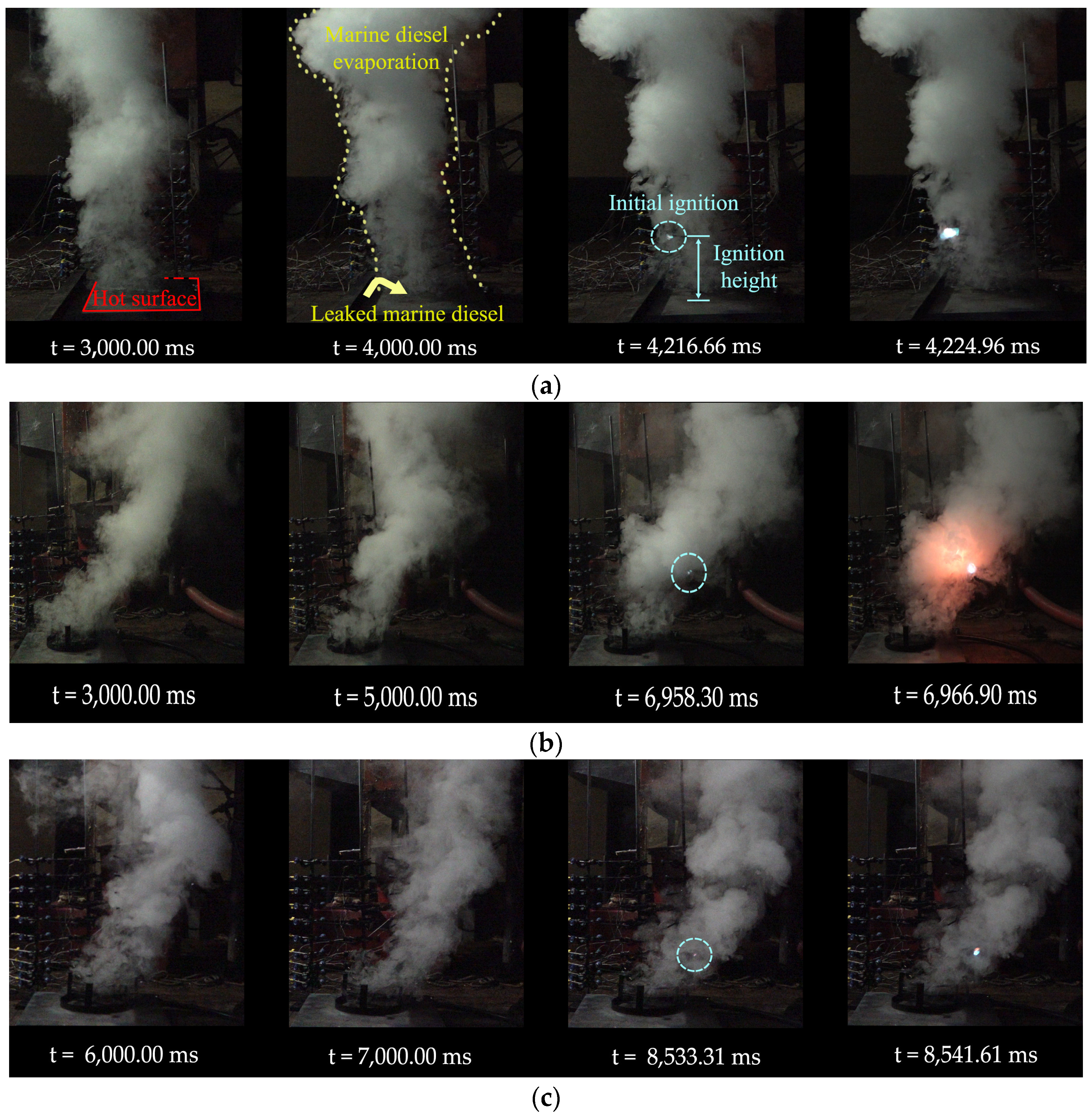
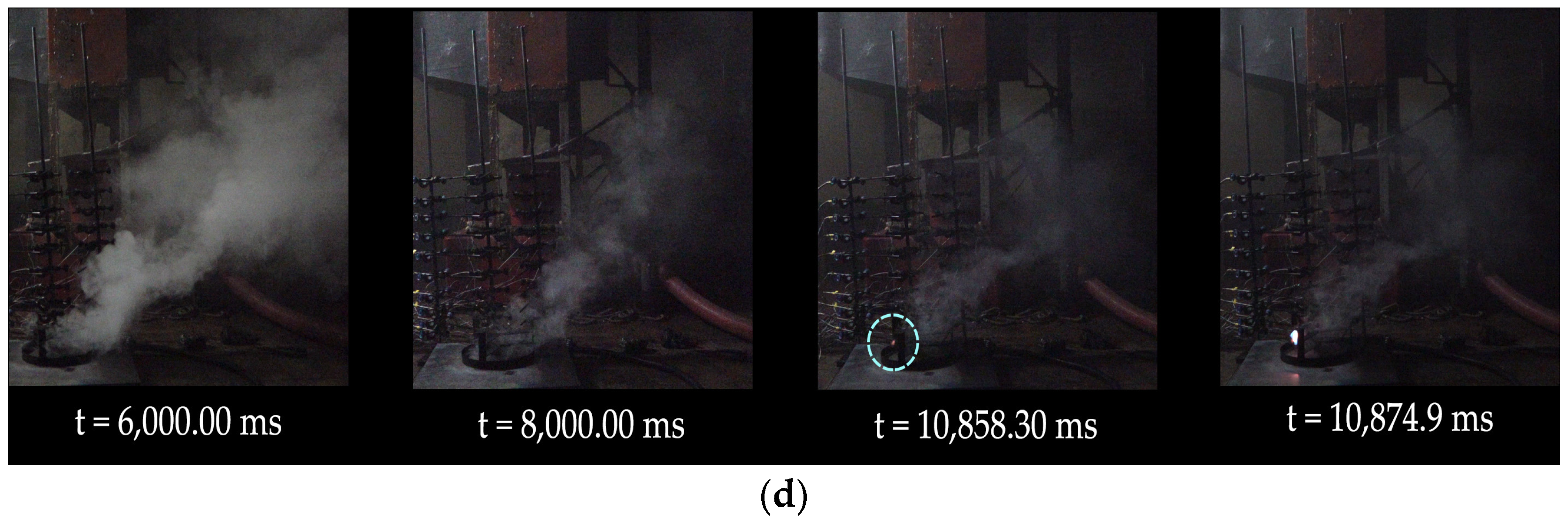
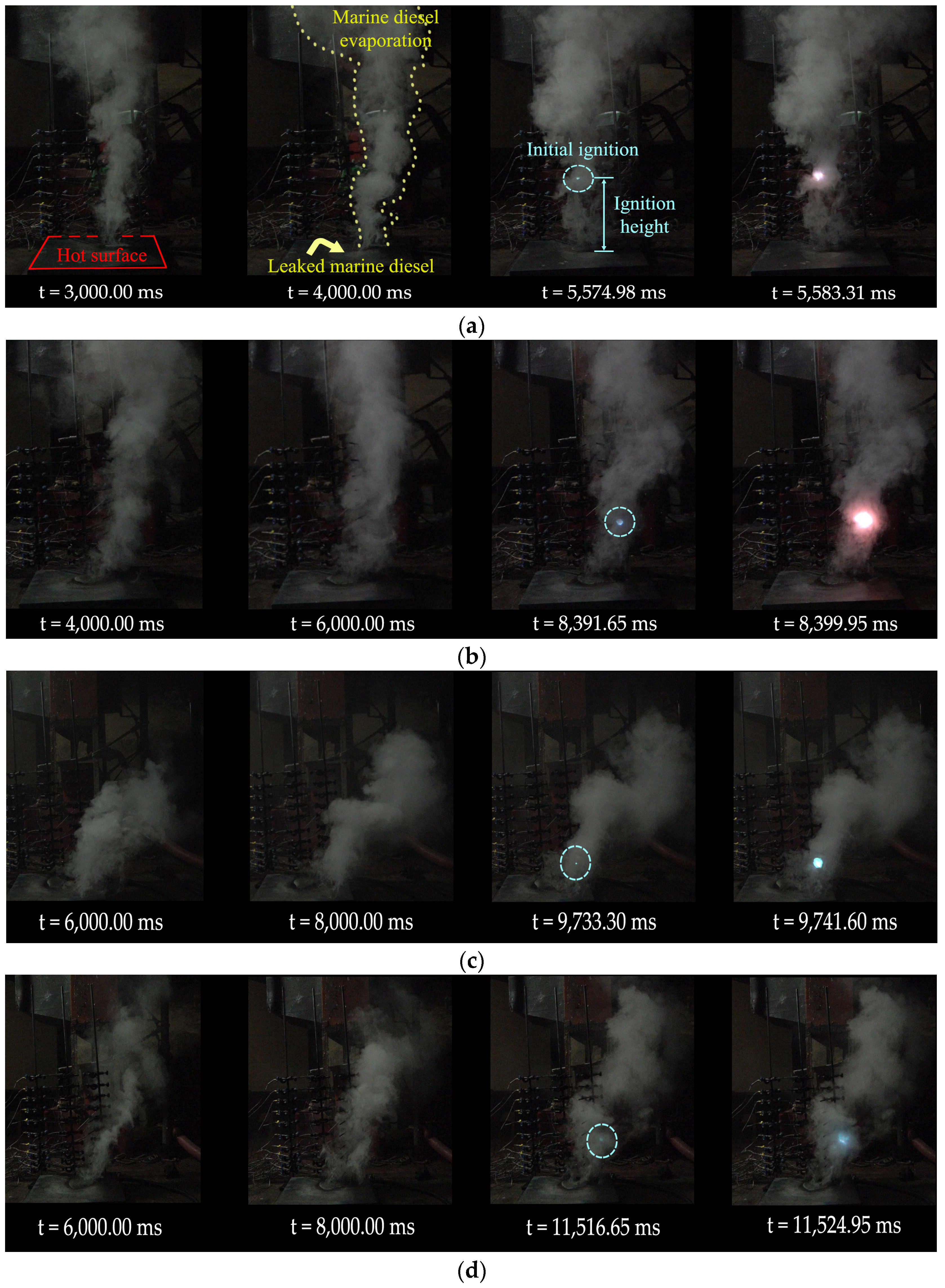
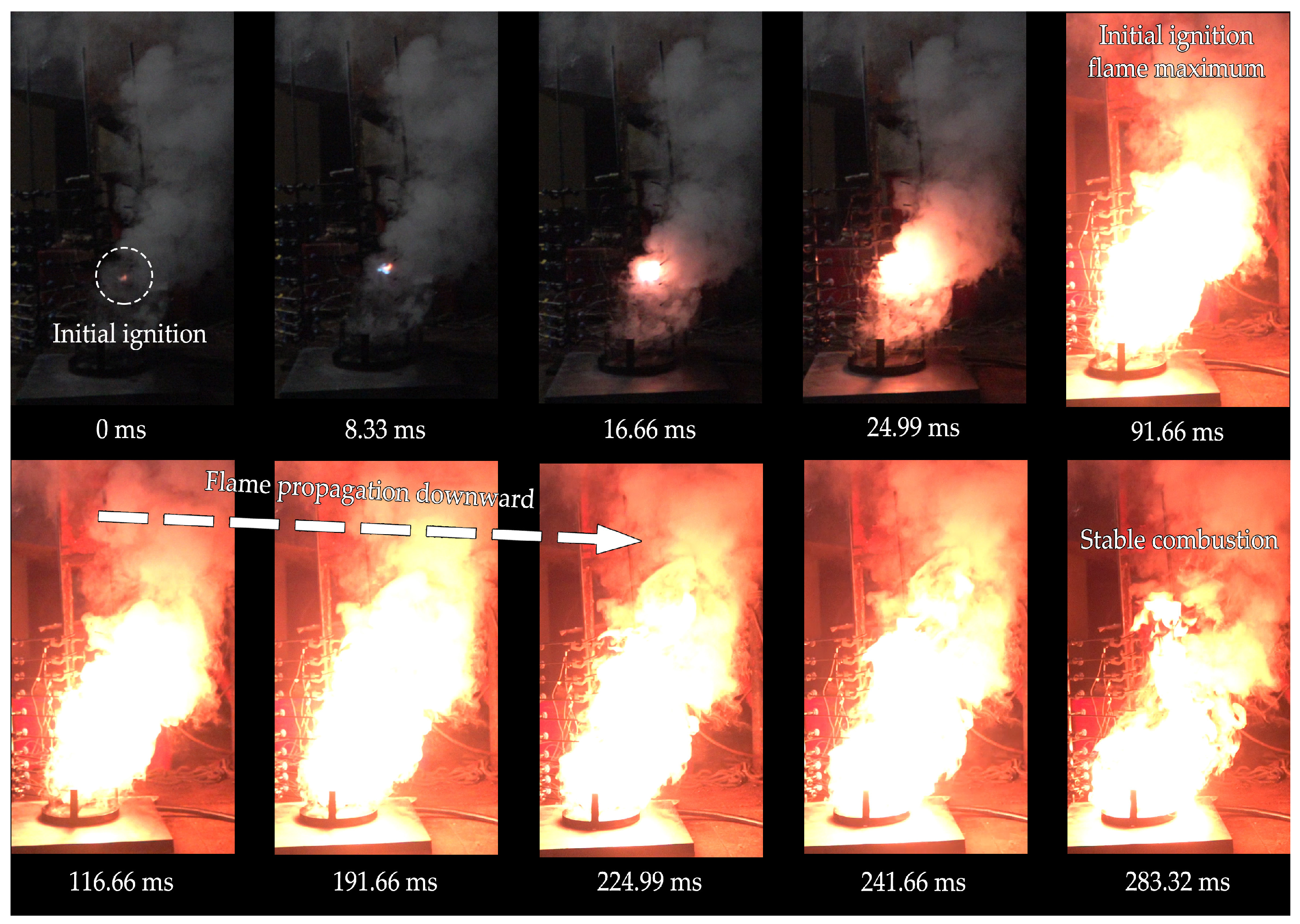
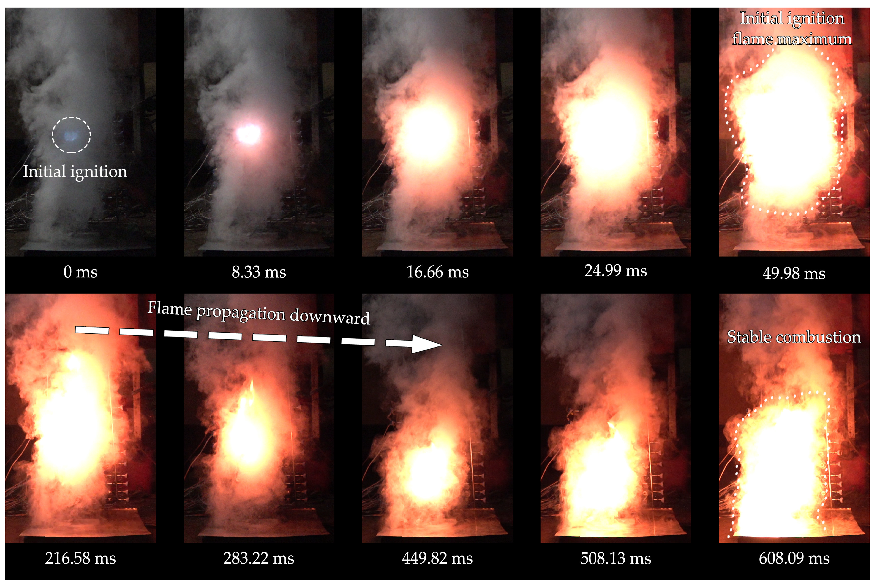
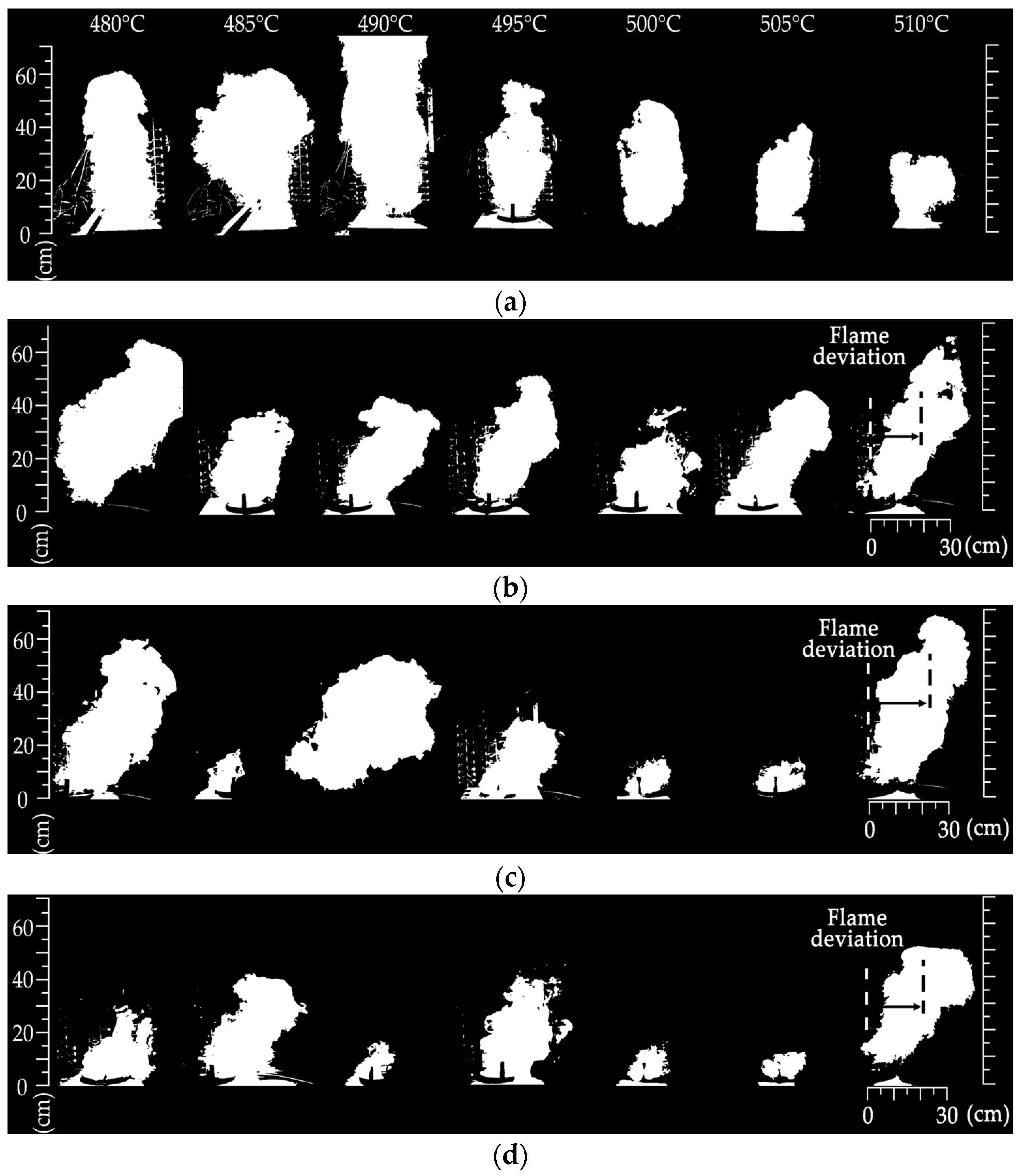
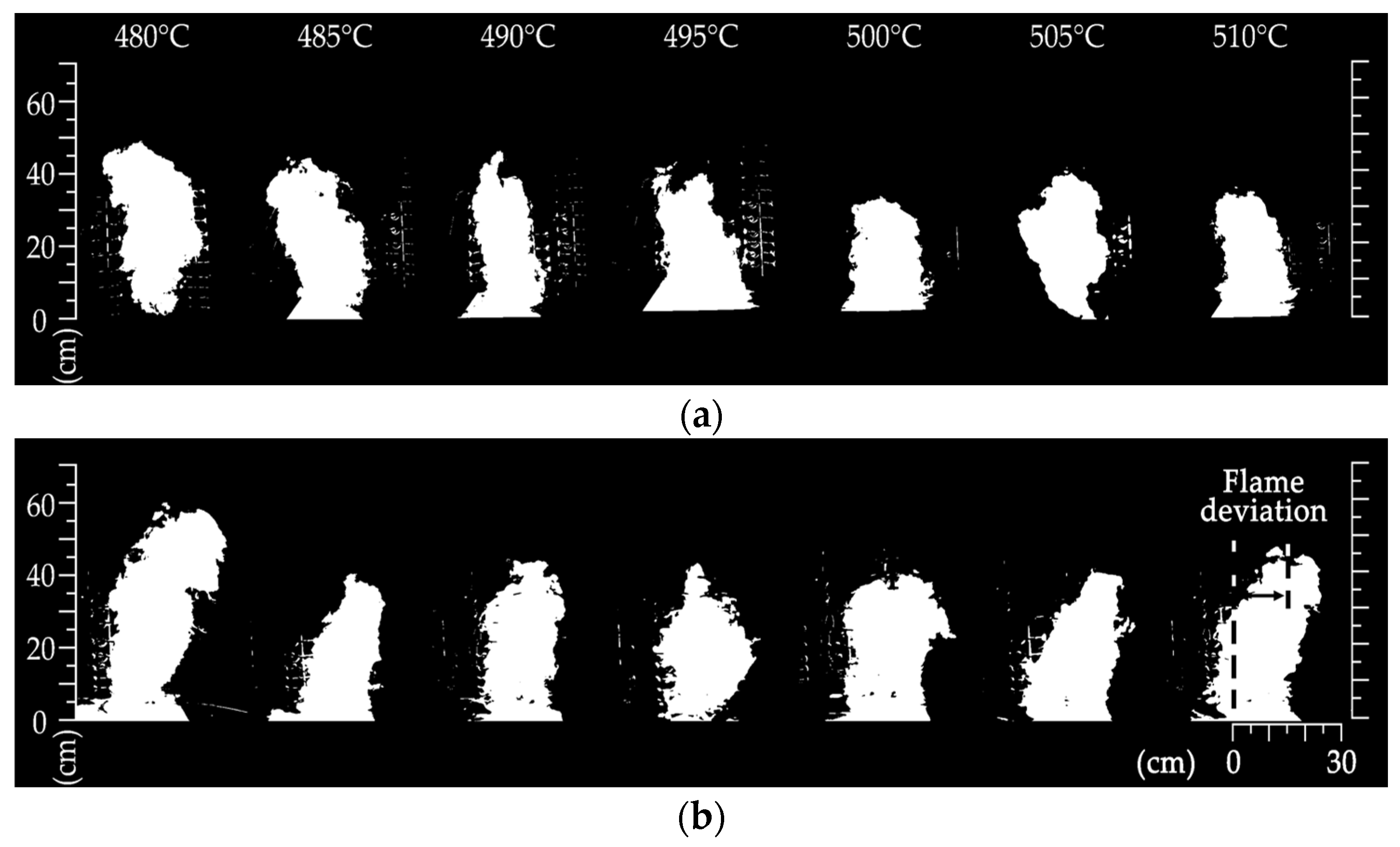
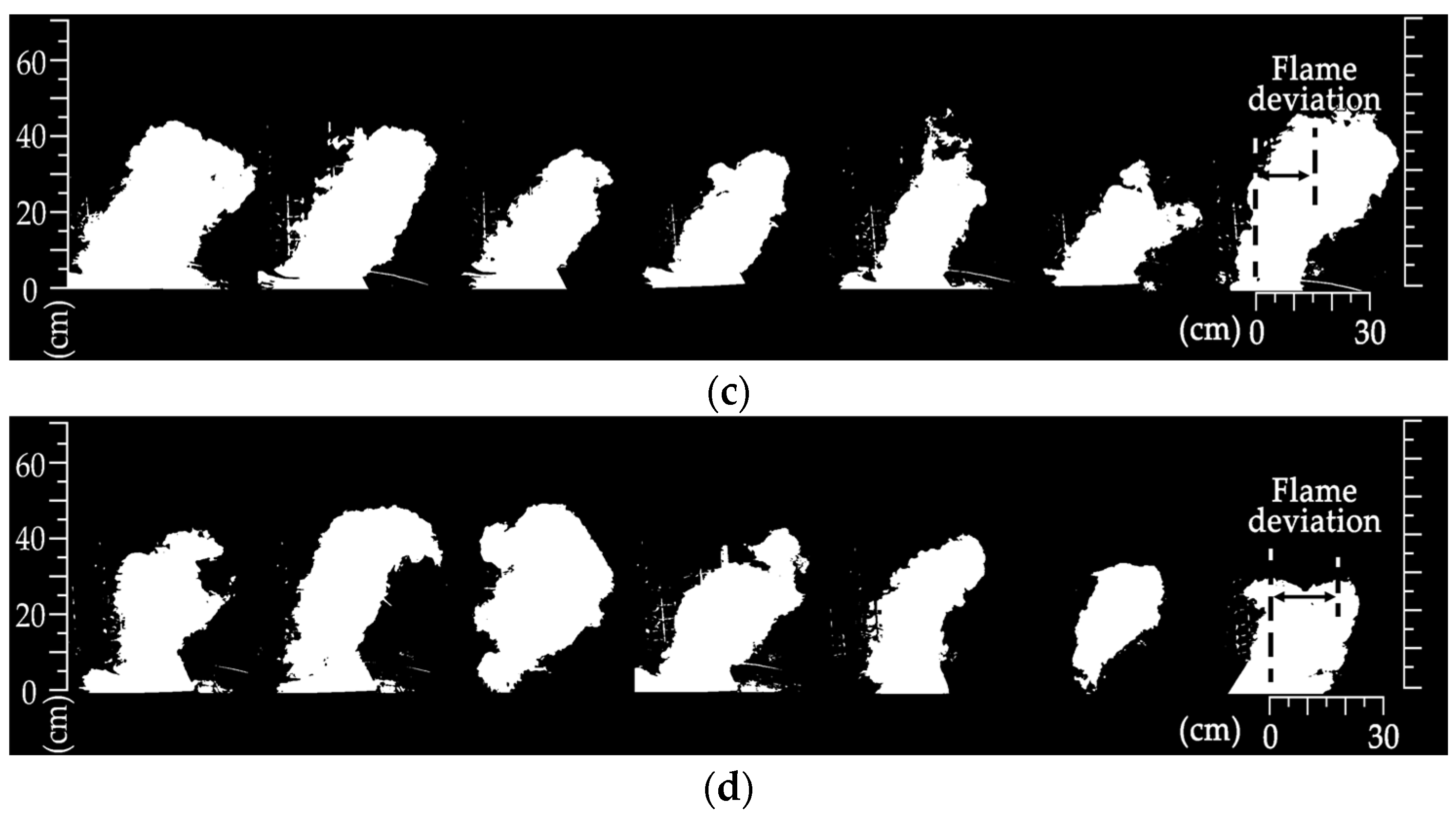
3.2. Flame Behaviors of Marine Fuel HSI under Different Airflows in Ship Engine Room

The leaked marine fuel is in full contact with the hot surface and forms an initial fire nucleus. After the initial ignition site phenomenon occurs, the flame spreads due to the accumulation of a highly concentrated combustible mixed gas around the fire core. Figure 7 shows the flame transmission process after the HSI of the marine diesel under mechanical ventilation shutdown in the engine room. When the hot-surface temperature reaches 495 °C, the HSI probability of the marine diesel can reach 93.1%. Under the windless conditions, the HSI position of the marine diesel appears to be directly above the hot surface. When the initial core is formed, the flame expands rapidly. At 8.33 ms after the initial fire core is formed, the fire core changes from the initial blue to red and yellow. This indicates that there is an incomplete combustion process that generates soot. Influenced by the high temperature, the carbon particles emit electromagnetic radiation with a longer wavelength, making the whole thermochemical reaction area appear red and yellow. At 16.66 ms after the initial HSI of the marine diesel, the bright flame expands to a large area. When the initial HSI occurs at 24.99 ms, the flame spread range in the horizontal direction reaches about 0.4 m. As the mixed vapor cloud in the initial ignition area continues to react, the gas-phase medium is further consumed. When the HSI of the marine diesel occurs at 216.58 ms, changes in the flame spread range can be observed, especially in the gradual narrowing of the flame range. This is due to the gradual depletion of the marine diesel vapor produced by phase transition under the action of the hot surface before the initial ignition occurs. When the HSI of the marine diesel occurs at 283.22 ms, the flame propagates to the hot surface in a relatively stable mode. Driven by the remaining marine diesel above the hot surface, phase change behavior is continuously stimulated. As a result, the flame spreads gradually to the area with remaining marine diesel until it comes into contact with the hot surface, forming a stable combustion phenomenon similar to a pool fire for a period of time. Due to the closure of the mechanical ventilation system in the ship engine room, flames start to propagate from the initial HSI position and present a vertical transmission of behavior.
Figure 8 shows the flame spread process after the HSI of the marine diesel in the ventilation scenario in the ship engine room. The hot-surface temperature is set at 495 °C, and the ventilation rate of the ship engine room is 1.0 m/s. According to the experimental results, it is found that, in the engine room with the top opening, the flame formed by the HSI of the marine diesel spreads and shows a tendency to tilt towards the upwind side under the action of mechanical ventilation. Affected by such mechanical ventilation in the ship engine room, the concentration distribution of the combustible vapor/air mixed cloud above the hot surface changes. As a result, the HSI height of the marine diesel under ventilation conditions is significantly lower than that under windless conditions. The ignition delay time required for the initial HSI of the marine diesel is longer than that in the windless scenario. When the initial HSI of the marine diesel develops at 16.66 ms, the flames begin to spread in all directions. At this time, it is found through observation that the flame expansion profile is not a regular ball shape but an overall shift towards the windward side. The experimental results show that, when there is mechanical ventilation in the ship engine room and the airflow velocity is small, the flame gradually shifts from vertical transmission to windward tilt. When the ventilation velocity of the ship engine room is 1.0 m/s, the transverse airflow velocity through the area near the hot surface is nearly 0.2 m/s. The airflow on the leeward side of the ship engine room forms a large-scale vortex along the bulkhead. The formation of this vortex drives the air to the upwind side, which causes the HSI-driven flame in the engine room to shift to the upwind side. However, the airflow on the upwind side consumes more combustion-supporting gases after the flame spread. The HSI-driven flame is more inclined to shift towards the area where the concentration of the combustible gas decreases rapidly. The result shows that a large amount of airflow on the windward side is sucked into the flame reaction zone, and a counterclockwise vortex is formed on the windward side. It also indicates that the flame form generated by the HSI of the marine diesel is jointly influenced by the buoyancy of hot airflow in the ship engine room, the fresh air suction on the leeward side, and the ventilation intensity.
Figure 9 shows the flame propagation of the marine diesel ignited on the hot surface of the ship engine room. The image is binarized so that the deviation profile in the flame propagation process can be presented more clearly. Figure 9a presents the changes in the HSI-driven flame of the marine diesel without mechanical ventilation in the ship engine room, which is used here for a comparison and reference. Figure 9b–d show the changes in the HSI-driven flame of the marine diesel during the period when the ventilation velocities in the ship engine room change from 1.0 m/s to 5.0 m/s. Figure 9a shows that, after the marine diesel is ignited on the hot surface, the flame is transferred to form a stable pool fire. In the absence of mechanical ventilation in the ship engine room, the flame generated by the leaked marine diesel on the hot surface spreads vertically. With the increase in the combustion time, the residual oil above the hot surface is gradually exhausted, and the flame height gradually decreases. When the ventilation velocity in the ship engine room is 1.0 m/s, the flame generated by the marine diesel tends to deviate towards the wind side during the combustion process of the hot surface. This is due to the restriction of air entrainment on the upwind side, resulting in a gradual bias of the flame pattern towards the side with a reduced oxygen concentration. Experimental measurements of the shift changes in the flame morphology are shown in Figure 9. The figure reveals how the deviation of the flame form changes with the increase in the hot-surface temperature under different ventilation scenarios. When the hot-surface temperature reaches 480 °C, ventilation has a great influence on the flame form of the marine diesel. Under a ventilation velocity of 1.0 m/s in the engine room, the flame horizontal deviation of the marine diesel on the hot surface reaches 0.301 m. With the increase in the hot-surface temperature, the deviation scale of the flame morphology decreases greatly. When the hot-surface temperature rises to about 490 °C, the flame deviation formed by the marine diesel’s HSI decreases to 0.206 m. Compared with a hot-surface temperature of 480 °C, the deviation of the flame pattern is reduced by 31.6%. As the hot-surface temperature further increases, the flame deviation amplitude of the marine diesel gradually stabilizes at a ventilation speed of 1.0 m/s. When the hot-surface temperature rises to 510 °C, the deviation of the flame shape is less than 0.128 m. With the change in the ventilation intensity in the ship engine room, the flame spread gradually shifts from the windward side to the vertical center line. Figure 9c shows that the ventilation velocity in the ship engine room increases to 3.0 m/s; however, the flame deviation degree decreases during the experiment. This analysis indicates that, due to the increase in the air velocity in the engine room, there is more airflow that drives the flame plume on the hot surface to the vertical center of the hot surface. In Figure 9c,d, it can be observed that the flame plume force formed by the HSI of the marine diesel and the vortex formed by the smoke plume force jointly promote the balance of the flame transfer. If the ventilation velocity in the engine room further increases, a symmetrical airflow vortex appears on the windward and leeward sides. The two vortices show a motion trajectory in the opposite directions, and this balance causes the flame to present a vertical transmission form again. Figure 10 shows the flame deviation of the marine diesel’s HSI with elevated hot-surface temperatures. When the airflow velocity in the ship engine room increases to 3.0 m/s, the flame deviation at a hot-surface temperature of 480 °C is approximately 0.273 m, which is 9.3% less than that at a ventilation velocity of 1.0 m/s. As the hot-surface temperature increases, the flame deviation eventually decreases to 0.076 m when the hot-surface temperature approaches 510 °C. When the ventilation rate in the ship engine room increases to 5.0 m/s, the flame generated by the HSI of the marine diesel becomes weaker and smaller. Figure 10 shows that the flame deviation fluctuates between 0.005 m and 0.10 m with a constant change in the hot-surface temperature. If the ventilation effect in the ship engine room is further enhanced, the HSI-driven flame shifts from the windward side to the leeward side. At this time, several small-scale airflow vortices appear on the upwind side of the burning flame above the hot surface. Enhanced lateral airflow drives the flame plume to the leeward side, resulting in the change in the flame’s morphological characteristics.
The marine diesel used in this experiment is light oil, which has a certain volatility, and its volatilization rate is obviously higher than that of the hydraulic oil after coming into contact with a hot surface. The kinematic viscosity of the hydraulic oil used is 46.5 mm2/s (313.15 K), which is obviously higher than that of the marine diesel. This is reflected in the experiment when the hydraulic oil comes into contact with a high-temperature hot surface, as it does not disperse like marine diesel but instead gathers near the leakage point. At the same time, the amount of gas-phase mixture produced by the hydraulic oil is significantly less than that produced by the marine diesel under the same conditions. This reveals that there is relatively less gas phase generated by the heat of the hydraulic oil, and more liquid medium is retained on the hot surface after its leakage. Therefore, the gas-phase combustion scale of the hydraulic oil is relatively small under the ventilation environment of the ship engine room. Figure 11 shows the variations in the HSI-driven flame of the hydraulic oil on the hot surface under ventilation conditions. Among the panels, Figure 11a presents the morphological changes in the hydraulic oil’s formed flame after HSI in the scenario without mechanical ventilation. It can be observed that the flame formed by the HSI of the hydraulic oil presents a relatively slender flame shape. This is basically consistent with the diffusion range of the flammable vapor generated by the hydraulic oil heated on a hot surface. Through experimental observation, it is found that the combustion process of the hydraulic oil is more stable after HSI, and the flame formed on the hot surface lasts longer. Figure 11b–d respectively show the variations in the morphology of the flames formed by the HSI of the hydraulic oil after the increase in the ventilation velocities in the ship engine room. When the ventilation velocity in the ship engine room reaches 1.0 m/s, the spread of the flames caused by the HSI of the hydraulic oil is obviously shifted towards the upwind side because of the large oxygen concentration consumed on the windward side and the large vortex generated on the leeward side. Figure 11 presents the deviation generated in the flame spread process of the HSI of the hydraulic oil under different ship engine room ventilation conditions. The experimental results show that, when the ventilation velocity in the ship engine room is 1.0 m/s, the flame deviation degree displays two different characteristics. When the hot-surface temperature is less than 495 °C, the flame deviation becomes relatively stable, staying at about 0.22 m. When the hot-surface temperature exceeds 495 °C, the flame deviation of the HSI of the hydraulic oil gradually decreases. When the hot-surface temperature rises to 510 °C, the deviation of the HSI-driven flame is less than 0.16 m. With the increase in the ventilation velocities in the ship engine room, the deviation degree of the flame towards the upwind side is intensified. When the ventilation velocity of the ship engine room increases to 3.0 m/s, it can be seen in Figure 11c that the deviation of the flame increases significantly. Under the ventilation of the engine room with enhanced force, the HSI-driven flame of the hydraulic oil moves towards the upwind side. At the same time, the scale of the flame gradually increases in the horizontal direction, which is significantly different from the results in the scenario without mechanical ventilation. Figure 12 shows the flame deviation of the hydraulic oil HSI with elevated hot-surface temperatures. It indicates that, when the ventilation velocity in the engine room increases to 3.0 m/s, the fluctuation amplitude of the flame deviation is obvious. When the hot-surface temperature reaches 485 °C, the flame deviation increases to 0.261 m. When the hot-surface temperature further increases to 490 °C, the flame deviation decreases from 0.261 m to 0.209 m. As the hot-surface temperature of the ship engine room continues to rise, the flame deviation eventually decreases to 0.181 m. The ventilation velocity in the ship engine room further increases to 5.0 m/s, and the flame deviation gradually begins to improve. Due to the high ventilation velocity of the ship engine room, a small amount of air enters the ship engine room along the leeward side wall and flows to the hot surface to drive the flame. Most of the gas drives the hydraulic oil flame and smoke plume in the ship engine room towards a leeward-side tilt. As can be seen in Figure 11d, the vortices formed by the two forces reach a balance on both sides of the flame. Meanwhile, symmetrical airflow vortices appear on the windward and leeward sides, prompting the flame to gradually approach the vertical center line. As shown in Figure 12, when the ventilation intensity of the engine room increases to a certain airflow velocity, the deviation degree of the HSI-driven flame presents a stationarity within a certain range. When the hot-surface temperature reaches 480 °C, the deviation of the flame of the hydraulic oil is approximately 0.161 m, which is reduced by 26.5% compared with the result in the scenario with an airflow velocity of 3.0 m/s. The hot-surface temperature increases from 485 °C to 510 °C, and the average flame deviation is 0.147 m. The deviation degree of the HSI-driven flame of the marine hydraulic oil changes smoothly in the ship engine room environment under the enhanced ventilation conditions.

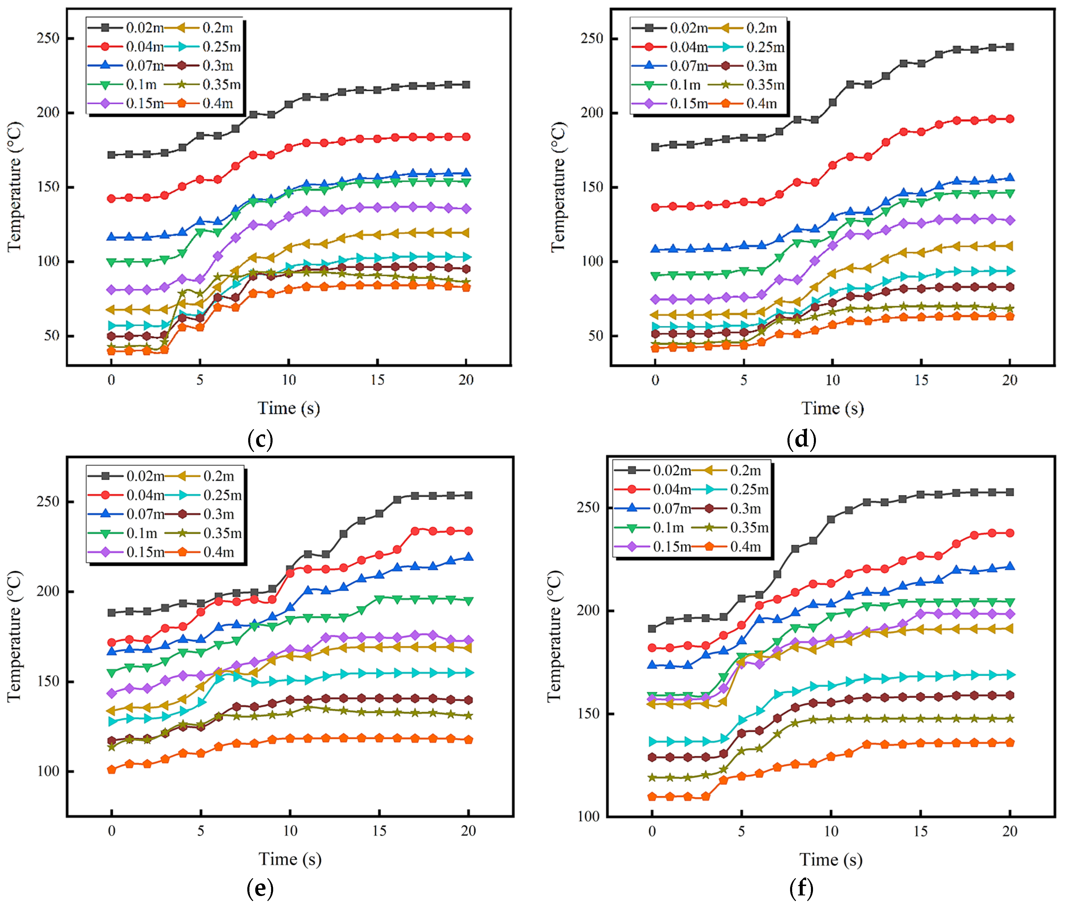
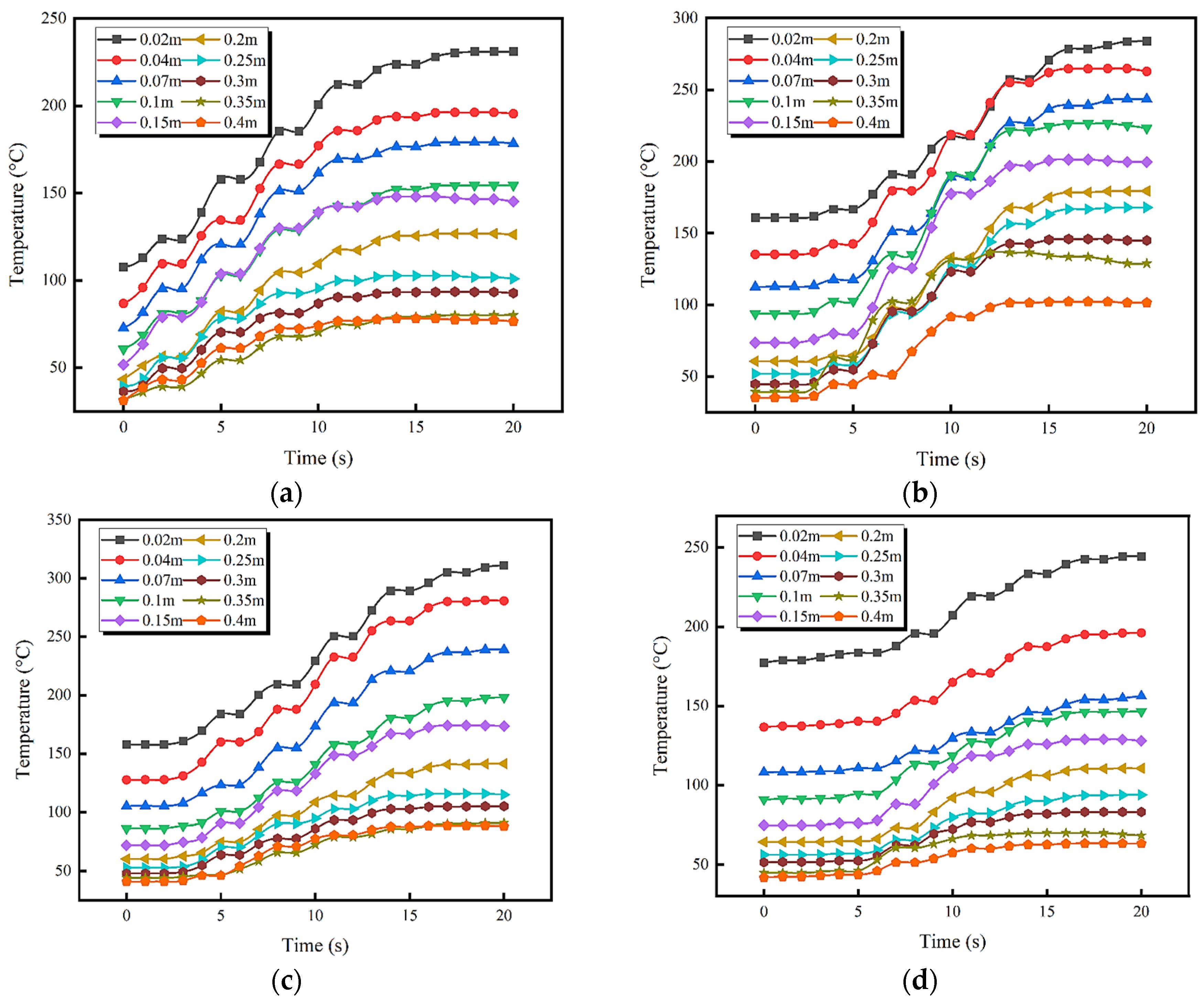
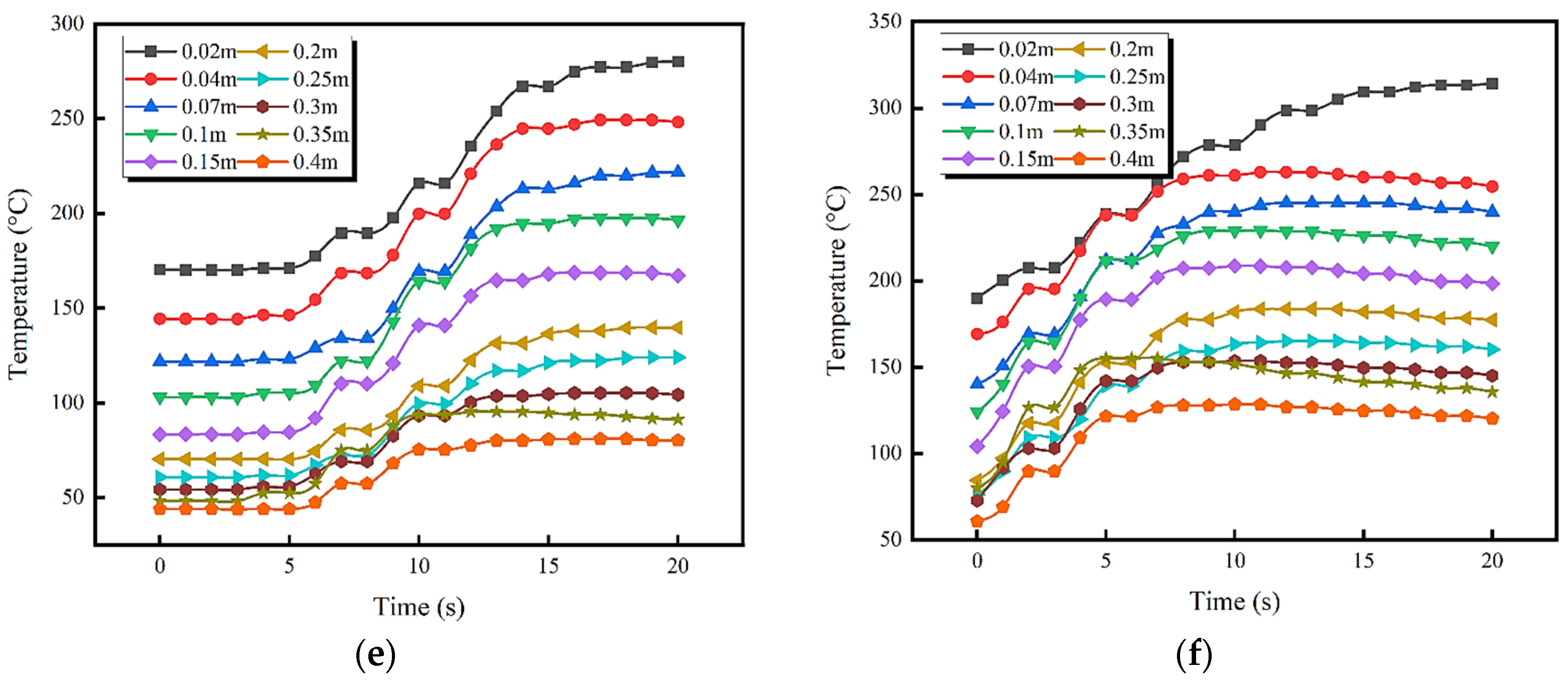
3.3. Temperature Field of Marine Fuel HSI with Different Hot-Surface Temperature

Temperature refers to the performance of heat in the initial HSI and the flame spread after HSI in the process of marine fuel leakage, and it serves as a key parameter of fire characteristics [47,48]. The difference in the HSI-driven flame and leaked fuel temperatures on a hot surface has a certain influence on thermal feedback, flame spreading speed, and oil mass loss rate. In this experiment, three rows of thermocouple bundles are arranged above the high-temperature hot surface in the ship engine room, with a total of 30 thermocouples installed in each bundle to collect temperature data from different vertical spaces. Figure 13 shows the temperature variation on the vertical center line during the HSI of the marine diesel. Among the panels, the typical hot-surface temperature of the ship engine room selected in this work ranges from 480 °C to 505 °C, and the ventilation velocity is set at 3.0 m/s. Due to the different spacing arrangements of the hot surface, the temperature data between 0.02 m and 0.4 m in the vertical space above the hot surface can be collected. Figure 13a indicates the vertical spatial temperature field distribution of the leaked marine diesel after it comes into contact with the hot surface when the temperature is 480 °C. It is found that, before the leaked marine diesel comes into contact with the hot surface, the temperature change at the highest point is close to that in the engine room. Due to the effect of thermal radiation generated by the hot surface, the temperature in the area near the hot surface is higher, exceeding 150 °C. The marine diesel comes into contact with the hot surface when the oil itself has a low temperature, which has a certain cooling effect on the temperature of the hot surface and significantly shortens the ignition time. Subsequently, the film boiling behavior of the marine diesel rapidly occurs above the hot surface, and it produces a large number of phase transition products. The generation of gas-phase products has a convective heat transfer effect in the vertical space, so the temperature in the vertical space begins to show an upward trend. The HSI of the marine diesel occurs when a particular concentration of combustible mixed gas is reached in the air direction space at a certain time. The temperatures at the vertical distances of 0.3 m and 0.35 m show a sudden jump, indicating that the initial fire core is formed in this region. This is consistent with the result showing that the HSI height of the marine diesel is 0.319 m in this scene, as determined with the high-speed camera. With the increase in the hot-surface temperature, the HSI delay time of the marine diesel is gradually shortened, and the temperature field in the vertical space shows such a changing trend. When the hot-surface temperature in the ship engine room rises to 485 °C, the temperature closest to the hot surface increases significantly. When the marine diesel reaches the HSI temperature, the temperature data at the vertical height of about 0.25 m to 0.3 m change dramatically. This indicates the location of HSI occurrence. This is consistent with the previous experimental results at the HSI height of 0.275 m. With the continuous increase in the hot-surface temperature, the HSI delay time of the hot surface of the marine diesel is further shortened. When the typical hot-surface temperature in the ship engine room rises to 500 °C, the temperature in the vertical space above the hot surface changes dramatically. Under the action of the high-temperature hot surface, the leaked marine diesel shows strong boiling heat transfer behavior on the hot surface. At the vertical height of 0.15 m above the hot surface, there are two obvious temperature rise phenomena. With the increase in the hot-surface temperature, the HSI time of the marine diesel is shortened. The temperature field distribution that the HSI height of the marine diesel appears between 0.1 m and 0.15 m when the hot-surface temperature is 500 °C, which is consistent with the actual situation. The results show that the leaked marine diesel has a strong phase transition and film boiling behavior with the increase in the typical hot-surface temperature in the ventilated ship engine room. The uneven temperature field distribution in the vertical space of the leaked marine diesel results in a local temperature jump, which reflects the correlation between the HSI position of the marine fuel and local temperature change.
By comparing the temperature field curves of the marine diesel and hydraulic oil, it is found that the flame plumes and the oil surface area of the hydraulic oil are higher at the same hot-surface temperature. This is related to the nature of marine fuel itself. The marine hydraulic oil has a higher kinematic viscosity and gathers near the leak point after leakage, which promotes the concentration of the flame formed after HSI. At the same time, the calorific value of the hydraulic oil is greater than that of the marine diesel, and the higher heat released during combustion also affects their temperature field distribution. Figure 14 shows the temperature field distribution in the vertical space after the hydraulic oil comes into contact with the hot surface in different temperature scenarios. In the same hot-surface temperature scenarios, the temperature field in the vertical space increases with time. Figure 14a presents the temperature distribution and change in the vertical space when the typical hot-surface temperature is 480 °C. Because the evaporation rate of the hydraulic oil on the hot surface is low, the temperature in the vertical space rises slowly, and there is no temperature jump within a short time. At the same time, this also indicates that the HSI delay time of the hydraulic oil is relatively long. When the hydraulic oil and hot surface come into contact 8000 ms later, the local temperature displays a sudden rise for the first time. It is found that the hydraulic oil is subjected to the action of the high-temperature hot surface, resulting in the production of the initial HSI-driven fire core. According to the temperature field, the specific initial ignition location is at a vertical height of around 0.15 m, which is somewhat different from the observed phenomenon. This indicates that, for hydraulic oil, it is not enough to accurately determine the initial ignition location merely through temperature field distribution and variation. There is more need to rely on the combination of temperature data and image data monitoring methods to prevent the occurrence of hydraulic oil HSI accidents more effectively. Figure 14b presents the temperature distribution and change in the vertical space when the hot-surface temperature reaches 485 °C. As the temperature rises to 485 °C, the temperature field distribution in the vertical space fluctuates more obviously. This may be caused by a competitive relationship between the hydraulic oil evaporation and the transverse ventilation of the ship engine room. This is mainly reflected in the phenomenon that, when the hydraulic oil comes into contact with the hot surface at 7500 ms, the temperatures at different vertical heights suddenly rise as a whole. At this time, the hydraulic oil shows initial HSI behavior in the vertical space, and then the flame pulsates under the influence of the transverse airflow. This results in significant fluctuations in the temperature field between 7500 ms and 10,000 ms. Figure 14c illustrates the temperature distribution above the hot surface at a temperature of 490 °C. The initial temperature in the vertical space of the hot surface is higher than that at 485 °C. There is a consistent trend of temperature change at 0.35–0.4 m above the hot surface, and it fluctuates between 7 and 9 s after the hydraulic oil comes into contact with the hot surface. When the hydraulic oil leaks on the hot surface for approximately 5 s, the temperature at 0.02–0.04 m above the hot surface shows an obvious rise. This indicates that a large number of high-temperature vapor clouds are gathered due to the thermal phase transformation of the hydraulic oil, leading to temperature changes in this height region. As the node of the hydraulic oil ignition delay time, the HSI of the hydraulic oil occurs on the hot surface. The vertical spatial temperature variation in the range of 0.07–0.15 m can be observed to produce a slight jump, which is close to the position of the hydraulic oil HSI. Figure 14d shows the temperature distribution and change in the vertical space when the hot-surface temperature is 495 °C. As the temperature of the hot surface increases, the vertical temperature field of the leaked hydraulic oil in contact with the hot surface continues to increase. The temperature change is the most obvious in the area closest to the hot surface, and the temperature distribution is maintained within the range of 180–240 °C from the contact of the hydraulic oil with the hot surface to ignition. The temperature distribution that converges furthest from the hot surface is different from that in the previous stage, which shows that the temperature at the vertical distance of 0.35 m exhibits jump behavior when HSI occurs. It is considered that the abovementioned phenomenon is caused by strong thermal feedback in the ship engine room. In Figure 14d, it can be clearly observed that the temperature distribution with significant fluctuations occurs around the vertical distance of 0.1–0.15 m. By comparing the experimental data, it is indicated that the HSI height of the leaked hydraulic oil is nearly 0.125 m. This is consistent with the results of the temperature field, which confirm the effectiveness of determining the HSI position using the temperature distribution method. As shown in Figure 14e, when the hot-surface temperature rises to 500 °C, the HSI probability of the hydraulic oil reaches 89.6%. After the hydraulic oil comes into contact with the hot surface, the temperature change in the vertical space is not drastic, but the overall temperature is slightly increased. When the hydraulic oil leaks on the hot surface for 5 s, the vertical space temperature change increases significantly. This indicates that the HSI delay time is shortened with a hot-surface temperature of 500 °C. When the hydraulic oil HSI occurs, the temperature in a certain range of the vertical space displays a sudden fluctuation. In particular, the temperature rise rate is the fastest within a vertical height range of 0.07–0.15 m, and the average temperature rise rate reaches 26.7 °C/s. Combined with the experimental data, it is found that the HSI position of the hydraulic oil is consistent with the occurrence of the temperature field jump phenomenon in the vertical space. Additionally, the temperature rises at a vertical height of 0.07–0.1 m are significant and indicate the occurrence of the initial fire nucleus. Figure 14f presents the temperature distribution and change in the vertical space when the hot-surface temperature is 505 °C. When the hot-surface temperature of the ship engine room rises to 505 °C, it can be found that the vertical temperatures at different heights have higher values at the initial moment. When the leaked marine hydraulic oil is in full contact with the hot surface, the delay time of the ignition caused by the hot-surface temperature is further shortened. When the marine oil comes into contact with the hot surface at about 4900 ms, the temperature of the local area in the vertical space shows a jump behavior. The sudden change in temperature is the most evident at vertical heights between 0.07 m and 0.1 m. This indicates a high agreement with the result at 0.077 m obtained in the measurement of the HSI height of the hydraulic oil. The results reveal that, when the hot-surface temperature of the ship engine room is low, the fluctuation of the marine hydraulic oil through the temperature field is significant and lasts for a long time. Under the ventilation condition of the ship engine room, with the increase in the hot-surface temperature, the location of the local temperature jump behavior shows a consistent trend with the variation in the actual HSI-driven height.

4. Conclusions

This study focuses on the HSI process of leaked marine fuel with enhanced lateral airflow velocities in a ship engine room. Certain new characteristics relating to HSI- driven flame propagation in both airflow velocities and ignition temperatures are discussed, and an underlying model of HSI height is further proposed. The main findings in this work can be concluded as follows:
  • The distance between the ignition height and leaked marine fuel is closely related to the hot-surface temperature and environmental factors. As lateral airflow increases to a critical velocity, the HSI height of marine fuel will no longer reduce but instead tends to ignite in a more stable area. HSI positions can be determined using prediction models, which are developed as Equations (8) and (9) in the current work.
  • With a constant change in the hot-surface temperature, the deviation of the HSI-driven flame of the marine diesel fluctuates between 0.005 and 0.10 m. As the hot-surface temperature increases from 485 to 510 °C, the average flame deviation of the hydraulic oil is 0.147 m. The flame deviation degree of the hydraulic oil HSI always changes smoothly under enhanced lateral airflow velocity.
  • The flame plumes of the hydraulic oil and oil surface area are higher at the same hot-surface temperature. An uneven temperature field distribution in the vertical space of the diesel produces a local temperature jump; meanwhile, the fluctuation of the hydraulic oil through the temperature field is significant and lasts for a long time with a low hot-surface temperature in a ship engine room.

Author Contributions

Conceptualization, K.W. and Y.H.; methodology, K.W.; software, X.L.; validation, Y.M., H.W. and Y.H.; formal analysis, K.W.; investigation, Y.M.; resources, K.W.; data curation, K.W. and X.L.; writing—original draft preparation, K.W. and Y.M.; writing—review and editing, Y.H., H.W. and X.L.; visualization, Y.M.; supervision, X.L.; project administration, K.W.; funding acquisition, K.W., Y.H. and X.L. All authors have read and agreed to the published version of the manuscript.

Funding

This research was funded by the 2023 Global Fisheries Resources Survey, Monitoring and Assessment Project, grant number D-8025-23-1001-04; National Natural Science Foundation of China, grant number 52001196; and Shanghai Key Projects of Soft Science, grant number 20692193100.

Institutional Review Board Statement

Not applicable.

Informed Consent Statement

Not applicable.

Data Availability Statement

The research data are presented in the current paper.

Acknowledgments

All authors would like to express their sincere thanks to the editor and reviewers for their significant comments.

Conflicts of Interest

The authors declare no conflict of interest.

Nomenclature

ASurface cross-sectional area, m
gAcceleration of gravity, m/s2
HmaxHeight during initial ignition, m
hFHeat transfer coefficient of transition boiling, W/m2∙K
kvfHeat conductivity of vapor in the film, W/(m·K)
qHeat flux, w/m2
TminInitial hot-surface temperature, °C
TsatFuel saturation temperature, L
ρLLiquid fuel density, kg/m3
σSurface tension of liquid, mN/m
ASETAvailable safe egress time
FDSFire dynamics simulator
MITMinimum ignition temperature
BMass transfer number, dimensionless
HfgLatent heat of vaporization, J/(kg °C)
HminHSI height of marine diesel during the stationary period, m
hnNuclear boiling heat transfer coefficient, W/m2∙K
mFFuel evaporation rate, gm/s
TmAverage change in temperature of hot surface, °C
TsHot-surface temperature, °C
TwHeated source temperature, K
ρvFuel vapor density, kg/m3
μvfViscosity of vapor in the film between wall and liquid, Pa∙s
AITAuto-ignition temperature
HSIHot-surface ignition

References

  1. Vukelic, G.; Ogrizovic, D.; Bernecic, D.; Glujic, D.; Vizentin, G. Application of VR technology for maritime firefighting and evacuation training—A review. J. Mar. Sci. Eng. 2023, 11, 1732. [Google Scholar] [CrossRef]
  2. Zhang, H.; Li, C.; Zhao, N.; Chen, B.-Q.; Ren, H.; Kang, J. Fire risk assessment in engine rooms considering the fire-induced domino effects. J. Mar. Sci. Eng. 2022, 10, 1685. [Google Scholar] [CrossRef]
  3. Wang, K.; Ming, Y.; Wang, H.; Liu, X.; Qian, X.; Shi, T. Failure analysis and correction models for upward flame characteristics subjected to shipping container fire. Eng. Fail. Anal. 2023, 152, 107519. [Google Scholar] [CrossRef]
  4. Allison, D.; Marchand, A.; Morchat, R. Fire performance of composite materials in ships and offshore structures. Mar. Struct. 1991, 4, 129–140. [Google Scholar] [CrossRef]
  5. Wang, K.; Wang, J.; Shi, T.; Qian, X.; He, Y. Effects of adjacent space on spill flame of chemical hazardous materials container fire. Int. J. Therm. Sci. 2020, 156, 106457. [Google Scholar] [CrossRef]
  6. Li, C.; Zhang, H.; Zhang, Y.; Kang, J. Fire risk assessment of a ship’s power system under the conditions of an engine room fire. J. Mar. Sci. Eng. 2022, 10, 1658. [Google Scholar] [CrossRef]
  7. Li, C.; Mao, J.; Kang, Z.; Zhao, S.; Ren, H. Influence of firefighting intervention on fire spread characteristics in ship engine room. J. Mar. Sci. Eng. 2023, 11, 877. [Google Scholar] [CrossRef]
  8. Kang, H.; Choi, J.; Lee, D.; Park, B. A framework for using computational fire simulations in the early phases of ship design. Ocean. Eng. 2017, 129, 335–342. [Google Scholar] [CrossRef]
  9. Wu, B.; Zong, L.; Yip, T.; Wang, Y. A probabilistic model for fatality estimation of ship fire accidents. Ocean. Eng. 2018, 170, 266–275. [Google Scholar] [CrossRef]
  10. Wang, J.; Jiao, Y.; Shi, L.; Xie, Q.; Li, G.; Liu, J.; Chen, W.; Zhang, S. An experimental and non-dimensional study on the vertical temperature distribution of a sealed ship engine room fire. Ocean. Eng. 2018, 165, 22–33. [Google Scholar] [CrossRef]
  11. Puisa, R.; Williams, S.; Vassalos, D. Towards an explanation of why onboard fires happen: The case of an engine room fire on the cruise ship “Le Boreal”. Appl. Ocean Res. 2019, 88, 223–232. [Google Scholar] [CrossRef]
  12. Sarıalioğlu, S.; Uğurlu, Ö.; Aydın, M.; Vardar, B.; Wang, J. A hybrid model for human-factor analysis of engine-room fires on ships: HFACS-PV&FFTA. Ocean Eng. 2020, 217, 107992. [Google Scholar] [CrossRef]
  13. Wang, J.; Cui, X.; Zhang, R.; Xie, Q.; Zhang, S.; Shi, L. Study on the mass loss rate of liquid pool fire in a well-confined ship cabin. Int. J. Therm. Sci. 2021, 166, 106984. [Google Scholar] [CrossRef]
  14. Wang, J.; Zhang, R.; Wang, Y.; Shi, L.; Zhang, S.; Li, C.; Zhang, Y.; Zhang, Q. Smoke filling and entrainment behaviors of fire in a sealed ship engine room. Ocean Eng. 2022, 245, 110521. [Google Scholar] [CrossRef]
  15. Wu, X.; Zhang, Y.; Jia, J.; Chen, X.; Yao, W.; Lu, S. Experimental and theoretical analysis of the smoke layer height in the engine room under the forced air condition. Fire 2023, 6, 16. [Google Scholar] [CrossRef]
  16. Zhang, S.; Fang, W.; Shi, L.; Liu, J.; Liu, J.; Wang, J.; Cong, B. Fire plume characteristics of annular pool fire with different cylindrical obstacles in a ship engine room. Ocean Eng. 2023, 276, 114253. [Google Scholar] [CrossRef]
  17. Xie, C.; Huang, L.; Wang, R.; Deng, J.; Shu, Y. Ship fire modelling and evacuation simulation in navigation tunnel. Tunn. Undergr. Space Technol. 2022, 126, 104546. [Google Scholar] [CrossRef]
  18. Liu, J.; Wang, Z.; Lu, K.; Zhang, R.; Li, H.; Zhang, S.; Wang, J. Phenomenological characteristics and flame radiation of dynamically evolving oil spill fires in a sealed ship engine room. Ocean Eng. 2023, 267, 113298. [Google Scholar] [CrossRef]
  19. Zeinali, D.; Mehaddi, R.; Ingold, F.; Parent, G.; Acem, Z.; Collin, A.; Torero, J.; Boulet, P. Experimental study of fire containment using water mist curtains in a reduced-scale deck of a ro-ro ship. Fire Saf. J. 2023, 140, 103835. [Google Scholar] [CrossRef]
  20. Zhu, J.; Zhang, J.; Wang, Y.; Ge, Y.; Zhang, Z.; Zhang, S. Fire detection in ship engine rooms based on deep learning. Sensors 2023, 23, 6552. [Google Scholar] [CrossRef]
  21. Meyer, L.; Beyer, M.; Krause, U. Hot surfaces generated by sliding metal contacts and their effectiveness as an ignition source. J. Loss Prev. Process Ind. 2015, 36, 532–538. [Google Scholar] [CrossRef]
  22. Meier, T.; Stathopoulos, P.; Rohr, P. Hot surface ignition of oxygen–ethanol hydrothermal flames. J. Supercrit. Fluids 2016, 107, 462–468. [Google Scholar] [CrossRef]
  23. Menon, S.; Boettcher, P.; Ventura, B.; Blanquart, G. Hot surface ignition of n-hexane in air. Combust. Flame 2016, 163, 42–53. [Google Scholar] [CrossRef]
  24. Boeck, L.; Meijers, M.; Kink, A.; Mével, R.; Shepherd, J. Ignition of fuel–air mixtures from a hot circular cylinder. Combust. Flame 2017, 185, 265–277. [Google Scholar] [CrossRef]
  25. Melguizo-Gavilanes, J.; Boeck, L.; Mével, R.; Shepherd, J. Hot surface ignition of stoichiometric hydrogen-air mixtures. Int. J. Hydrog. Energy 2017, 42, 7393–7403. [Google Scholar] [CrossRef]
  26. Boeck, L.; Melguizo-Gavilanes, J.; Shepherd, J. Hot surface ignition dynamics in premixed hydrogen–air near the lean flammability limit. Combust. Flame 2019, 210, 467–478. [Google Scholar] [CrossRef]
  27. Mével, R.; Melguizo-Gavilanes, J.; Boeck, L.; Shepherd, J. Experimental and numerical study of the ignition of hydrogen-air mixtures by a localized stationary hot surface. Int. J. Heat Fluid Flow 2019, 76, 154–169. [Google Scholar] [CrossRef]
  28. Eckhoff, R. Measuring hot-surface minimum ignition temperatures of dust clouds—History, present, future. J. Loss Prev. Process Ind. 2019, 59, 63–76. [Google Scholar] [CrossRef]
  29. Li, B.; Li, M.; Gao, W.; Bi, M.; Ma, L.; Qin, Q.; Shu, C. Effects of particle size on the self-ignition behaviour of a coal dust layer on a hot plate. Fuel 2020, 260, 116269. [Google Scholar] [CrossRef]
  30. Mohaddes, D.; Boettcher, P.; Ihme, M. Hot surface ignition of a wall-impinging fuel spray: Modeling and analysis using large-eddy simulation. Combust. Flame 2021, 228, 443–456. [Google Scholar] [CrossRef]
  31. Mohaddes, D.; Ihme, M. On the hot surface ignition of a wall-stagnating spray flame. Combust. Flame 2022, 240, 111988. [Google Scholar] [CrossRef]
  32. Wang, K.; He, Y.; Liu, Z.; Qian, X. Experimental study on optimization models for evaluation of fireball characteristics and thermal hazards induced by LNG vapor Cloud explosions based on colorimetric thermometry. J. Hazard. Mater. 2019, 366, 282–292. [Google Scholar] [CrossRef] [PubMed]
  33. Wang, K.; Zhou, Z.; Ming, Y.; Qian, X. Research on hot surface ignition characteristics of leaking fuel in ship engine room. Therm. Sci. 2023, 27, 2813–2829. [Google Scholar] [CrossRef]
  34. Su, S.; Wang, L.; Nie, Y.; Gu, X. Numerical computation and characteristic analysis on the center shift of fire whirls in a ship engine room fire. Saf. Sci. 2012, 50, 12–18. [Google Scholar] [CrossRef]
  35. Wang, K.; Liu, Z.; Qian, X.; Huang, P. Long-term consequence and vulnerability assessment of thermal radiation hazard from LNG explosive fireball in open space based on full-scale experiment and PHAST. J. Loss Prev. Process Ind. 2017, 46, 13–22. [Google Scholar] [CrossRef]
  36. Lin, C.; Silcock, G.; Delichatsios, M. Flame interactions and smoke containment by downward displacement ventilation. Combust. Flame 2007, 150, 210–219. [Google Scholar] [CrossRef]
  37. Guo, F.; Ding, L.; Gao, Z.; Yu, L.; Ji, J. Effects of wind flow and sidewall restriction on the geometric characteristics of propane diffusion flames in tunnels. Energy 2020, 198, 117332. [Google Scholar] [CrossRef]
  38. Wang, L.; Guo, Y.; Xia, Z.; Lao, X.; Su, S.; Yuan, Z.; Wu, Z. Experimental study on mass burning rate and flame geometry of pool fires under two-way indirect ventilation in Ship’s engine room. Case Stud. Therm. Eng. 2023, 41, 102595. [Google Scholar] [CrossRef]
  39. Wang, K.; Ming, Y.; Zhao, H.; Jiao, Y.; Shi, T.; Zhang, Q. Effect of shock-flame interactions on initial damage characteristics in highway tunnel under hazmat tanker truck accident. Tunn. Undergr. Space Technol. 2022, 130, 104763. [Google Scholar] [CrossRef]
  40. Lan, Q.; Han, F.; Liu, Y.; Li, W.; Wang, Z. Effects of ventilation system design on flame behavior and smoke characteristics for mitigating marine engine room fire hazards. Ocean Eng. 2023, 281, 114890. [Google Scholar] [CrossRef]
  41. Robinet, A.; Chetehouna, K.; Junjunan, S.; Cablé, A.; Oger, A. Thermal and spectral analysis of a pool fire in an engine compartment: Experimental study on the influence of ventilation and fuel depth. Process Saf. Environ. Prot. 2023, 174, 200–213. [Google Scholar] [CrossRef]
  42. Johnson, A.M.; Roth, A.J.; Moussa, N.A. Hot-Surface Ignition Tests of Aircraft Fluids; Final Report; Boeing Advanced Systems Co.: Seattle, WA, USA, 1988. [Google Scholar]
  43. Berenson, P.J. Film-boiling heat transfer from a horizontal surface. J. Heat Transf. 1961, 83, 351–356. [Google Scholar] [CrossRef]
  44. Song, M.; Liu, X.; Cheng, X. Modelling and experimental validation of heat transfer behavior during trans-critical transients. Ann. Nucl. Energy 2023, 186, 109771. [Google Scholar] [CrossRef]
  45. Veza, I.; Irianto; Hoang, A.T.; Yusuf, A.A.; Herawan, S.G.; Soudagar, M.E.M.; Samuel, O.D.; Said, M.F.M.; Silitonga, A.S. Effects of Acetone-Butanol-Ethanol (ABE) addition on HCCI-DI engine performance, combustion and emission. Fuel 2023, 333, 126377. [Google Scholar] [CrossRef]
  46. Djamari, D.W.; Idris, M.; Paristiawan, P.A.; Abbas, M.M.; Samuel, O.D.; Soudagar, M.E.M.; Herawan, S.G.; Chandran, D.; Yusuf, A.A.; Panchal, H.; et al. Diesel Spray: Development of Spray in Diesel Engine. Sustainability 2022, 14, 15902. [Google Scholar] [CrossRef]
  47. Nassiraei, H. Static strength of tubular T/Y-joints reinforced with collar plates at fire induced elevated temperature. Mar. Struct. 2019, 67, 102635. [Google Scholar] [CrossRef]
  48. Nassiraei, H.; Zhu, L.; Lotfollahi-Yaghin, M.A.; Ahmadi, H. Static capacity of tubular X-joints reinforced with collar plate subjected to brace compression. Thin-Walled Struct. 2017, 119, 256–265. [Google Scholar] [CrossRef]
Figure 1. Schematic diagram of full-scale ship engine room and experimental system.
Jmse 12 00005 g001
Figure 2. Arrangement of 30 thermocouples in the ship engine room laboratory.
Jmse 12 00005 g002
Figure 3. Initial ignition process of leaked marine diesel on hot surface: (a) windless; (b) airflow velocity of 1.0 m/s; (c) airflow velocity of 3.0 m/s; (d) airflow velocity of 5.0 m/s.
Jmse 12 00005 g003aJmse 12 00005 g003b
Figure 4. Initial ignition processes of leaked marine hydraulic oil on hot surface: (a) windless; (b) airflow velocity of 1.0 m/s; (c) airflow velocity of 3.0 m/s; (d) airflow velocity of 5.0 m/s.
Jmse 12 00005 g004
Figure 5. HSI heights of leaked diesel with different hot-surface temperatures in ship engine room.
Jmse 12 00005 g005
Figure 6. HSI heights of hydraulic oil with different hot-surface temperatures in ship engine room.
Jmse 12 00005 g006
Figure 7. Ignition and flame propagation of marine diesel by hot surface without airflow.
Jmse 12 00005 g007
Figure 8. Ignition and flame propagation of leaked marine diesel by hot surface with airflow.
Jmse 12 00005 g008
Figure 9. Flame deviation induced by marine diesel HSI: (a) windless; (b) airflow velocity of 1.0 m/s; (c) airflow velocity of 3.0 m/s; (d) airflow velocity of 5.0 m/s.
Jmse 12 00005 g009
Figure 10. Flame deviation of marine diesel HSI with elevated hot-surface temperature.
Jmse 12 00005 g010
Figure 11. Flame deviation induced by marine hydraulic oil HSI: (a) windless; (b) airflow velocity of 1.0 m/s; (c) airflow velocity of 3.0 m/s; (d) airflow velocity of 5.0 m/s.
Jmse 12 00005 g011aJmse 12 00005 g011b
Figure 12. Flame deviation of marine hydraulic oil HSI with elevated hot-surface temperature.
Jmse 12 00005 g012
Figure 13. Central temperature field of marine diesel HSI above hot surface: (a) hot-surface temperature of 480 °C; (b) hot-surface temperature of 485 °C; (c) hot-surface temperature of 490 °C; (d) hot- surface temperature of 495 °C; (e) hot-surface temperature of 500 °C; (f) hot-surface temperature of 505 °C.
Jmse 12 00005 g013aJmse 12 00005 g013b
Figure 14. Central temperature field of marine hydraulic oil HSI above hot surface: (a) hot-surface temperature of 480 °C; (b) hot-surface temperature of 485 °C; (c) hot-surface temperature of 490 °C; (d) hot-surface temperature of 495 °C; (e) hot-surface temperature of 500 °C; (f) hot-surface temperature of 505 °C.
Jmse 12 00005 g014aJmse 12 00005 g014b
Table 1. Characteristic parameters of marine fuel used in current experiment.
MaterialDensity
(293.15 K, kg/m3)
Kinematic Viscosity
(313.15 K, mm2/s)
Flash Point
(K)
Pour Point
(K)
Surface
Tension
(mN/m)
Heat Value
(×107 J/kg)
Marine diesel8503.547325526.83.3
Hydraulic oil90046.550325833.93.9
Disclaimer/Publisher’s Note: The statements, opinions and data contained in all publications are solely those of the individual author(s) and contributor(s) and not of MDPI and/or the editor(s). MDPI and/or the editor(s) disclaim responsibility for any injury to people or property resulting from any ideas, methods, instructions or products referred to in the content.

