Abstract
In order to harness a greater share of wind energy resources, offshore wind energy projects are venturing into deep-sea locations. In this progression, the issue of grid integration control becomes increasingly challenging. Traditional Model Predictive Control (MPC) has been introduced in offshore wind energy grid integration control due to its merits, such as not requiring modulators, dispensing with decoupling, incorporating constraint handling, and facilitating online optimization. However, it heavily relies on a model and consequently experiences a substantial loss of control effectiveness in the face of system parameter variations. In light of this, this study presents an active-disturbance-rejection-based three-vector sequence model predictive control approach. This method effectively mitigates the influence caused by changes in system parameters, endowing the system with self-disturbance rejection capabilities and enhancing its fault recovery abilities. The method employs self-disturbance control to track voltage reference values and employs the concept of sequence control to eliminate weighting factors in the cost function. Furthermore, it employs three-vector control to achieve error-free operation. The simulation results confirmed that the proposed method effectively minimizes voltage and power transients. It demonstrated superior control effectiveness and shorter response times, enabling the system to rapidly restore to a stable operational state following disturbances.
1. Introduction
The crises of energy security, extreme weather events, and others have deepened the awareness of the importance and urgency of energy transition in an increasing number of countries [1]. Global renewable energy installations have achieved historically remarkable growth, constituting 83% of the total new electricity generation capacity. Offshore wind power development has been particularly conspicuous and is increasingly playing an important role in promoting economic growth and enhancing energy security [2].
With the large-scale development of offshore resources and the quest for greater wind energy resources, offshore wind energy projects are gradually expanding into deeper offshore regions. The overall project planning exhibits a shift from nearshore to offshore, from shallow waters to deep waters, and from small-scale demonstrations to large-scale concentrated development. Furthermore, offshore wind energy is highly susceptible to environmental factors, resulting in pronounced output variability and unpredictability [3]. When integrated into the grid, this unpredictability directly impacts grid safety and reliability. As offshore wind farms transition toward large-scale and long-distance development, the challenges of grid integration become increasingly severe [4].
Currently, offshore wind farms commonly employ a dual-closed-loop control strategy of alternating current voltage and alternating current for their output [5]. The control objectives for wind turbine generators are their active and reactive power outputs. The grid-side converter of the wind power converter adopts a dual-closed-loop control scheme for direct current bus voltage and alternating current, providing a constant direct current voltage for the generator-side converter. The generator-side converter operates in maximum power point tracking mode, regulating the generator torque to enable variable-speed operation of the wind turbine, thereby capturing maximum wind energy.
References [6,7,8] initially introduced a control method that utilizes converters to support the voltage and frequency of the wind farm. This approach employs the grid-side converter of the wind turbine generator to control the voltage and frequency at the grid connection point, with the direct current bus voltage controlled by the generator-side converter. Reference [9] proposed a distributed voltage–frequency control method based on a phase-locked loop. This method also employs the generator-side converter to control the direct current bus voltage, whereas the grid-side converter utilizes distributed Q/f droop control to uniformly distribute reactive power.
The aforementioned control methods all employ traditional PI controllers. However, traditional PI controllers exhibit poor performance, especially during transient fault periods.
In order to address this issue, many experts and scholars have begun to incorporate Model Predictive Control (MPC) into the control strategies of converter stations. The primary characteristic of this control type is the use of a system model to predict the future behavior of the controlled variables. The controller utilizes this information, in accordance with predefined performance criteria, to determine the optimal switching signals. MPC eliminates the need for modulators and decoupling, accommodates constraints, and allows for online optimization.
In reference [10], predictive direct torque control based on a fixed-frequency model is applied for control, with the grid-side converter using predictive direct power control based on a finite-set model. References [11,12] propose a direct model predictive control scheme that integrates instantaneous power calculations for a three-level back-to-back converter with a permanent magnet synchronous generator wind turbine system. In references [13,14,15], a double-sampling advanced predictive range Finite Control Set Model Predictive Control (FCS-MPC) for a four-bridge-arm Neutral Point Clamped (NPC) inverter is designed to achieve high-performance operation at low switching frequencies. The results indicate the advantage of double sampling in low-switching-frequency operation.
Due to its reliance on model-based system state predictions, MPC is susceptible to model bias (e.g., arising from inaccurate modeling and incorrect component parameters) [16,17,18,19,20,21]. In fact, system parameters can change during wind turbine operation, such as coil inductance, load resistance, and so on. When the system model exhibits bias, the accuracy of future predictions diminishes, resulting in a significant reduction in control effectiveness. To address this issue, scholars have introduced robust MPC with error compensation, as illustrated by [22]. This method incorporates the error between measured and predicted variable values in the prediction, compensating for the deviations in state tracking caused by parameter mismatch. This approach relies on the system model but compensates for model uncertainties by adding compensation values. However, the calculation of these compensation values is not straightforward.
Another proposal involves using a model-free or data-driven approach, as discussed in [23,24]. These methods leverage historical data instead of model information, thereby minimizing the impact of model deviations on the controller’s performance. Nevertheless, these solutions either demand high computational loads to generate control outputs or are influenced by a very slow variable update mechanism, occasionally resulting in unstable operations.
To address the above problems, this paper proposes a three-vector sequential model predictive control method that can effectively suppress the effects caused by the changes of system parameters and endow the system with self-disturbance rejection capabilities and verifies the method on the control of an offshore wind farm via a double-ended VSC-HVDC grid-connected system. The main contributions of this paper include:
- A three-vector sequential model predictive control method based on active disturbance rejection is proposed for the grid-connected wind-side VSC converter station of offshore wind farms. Replacing the PID controller utilized for tracking reference values in traditional MPC control with an ADRC controller effectively mitigates the impact of unpredictable disturbances on system performance. This modification endows the system with disturbance rejection capabilities, enhancing its robustness and resilience.
- Within one cycle, the three-vector control achieves error-free control, resolving the drawbacks of traditional MPC, which does not accomplish precise tracking and has longer computation times. Moreover, for the multi-objective control of offshore wind farms, a sequential model predictive control approach has been applied, addressing both multi-objective control and the challenge of weight coefficient selection.
- The proposed method is tested with conventional MPC in various scenarios and its dynamic performance is analyzed and compared.
The main contents of this paper: Section 2 introduces the offshore wind farm side converter station topology and the wind farm side converter station prediction model; Section 3 describes the principle and the design process of the proposed control method; Section 4 is the comparative validation and analysis of the proposed method and the traditional method; and Section 5 concludes the paper.
2. Topology and Prediction Model of Offshore Wind Farm-Side Converter Station
Figure 1 illustrates the topological structure of offshore wind farm integration into the grid via a dual-end Flexible DC Transmission System (VSC-HVDC). The system comprises the offshore wind farm, the VSC-HVDC transmission system, and the alternating current grid. The VSC-HVDC transmission system includes the Wind-Farm-Side Voltage-Source Converter (WF-VSC), the Grid-Side Voltage-Source Converter (GS-VSC), and the undersea DC transmission lines. To ensure the grid integration and power absorption of the offshore wind farm output, as well as the safe operation of the VSC-HVDC transmission system, it is crucial to maintain power balance. Therefore, the primary functions of the WF-VSC are to sustain the power balance on the wind farm side and ensure the voltage magnitude stability of the direct current bus.
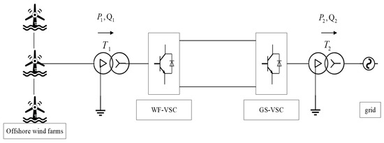
Figure 1.
Schematic diagram of offshore wind farm connected to the grid through VSC-HVDC.
The topology of the WF-VSC is shown in Figure 2.
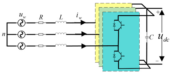
Figure 2.
Topology diagram of converter station on the wind farm side.
The theoretical model of the WF-VSC in the two-phase αβ stationary coordinate system is given by Equation (1):
where and represent the components of the injected AC bus voltage at the α and β axes for the wind farm, and denote the components of the injected AC bus current at the α and β axes for the wind farm, signifies the DC bus voltage, and are the switching functions, and and stand for the components of the AC-side voltage at the converter station in the α and β axes.
The grid voltage may introduce harmonics. To overcome the influence of these harmonics on the controller and maintain system stability, the virtual flux technique is employed. Based on this, the WF-VSC power is calculated using the virtual flux technique method to achieve control. Combining with Formula (1), according to the definition of virtual flux linkage, the integration of the wind-farm-side voltage yields the following equation:
where and represent the components of the virtual flux linkage φ in the α and β coordinates and L stands for the filtering inductance. According to instantaneous power theory, the instantaneous active and reactive power of the VSC system in the coordinate system are as follows:
where ω is the angular frequency of the AC grid voltage. According to Formula (3), the values of active and reactive power are obtained and their derivatives with respect to the time for the active and reactive power rates of change are as follows:
The instantaneous rate of change in grid voltage under ideal conditions can be expressed as:
Using the Euler method for active and reactive power, the predicted values are as follows:
The model for predictive power control of the wind-farm-side converter station at time is as follows:
where , , , and are the grid-side instantaneous current values at time (k + 1) and k in the αβ coordinate system and denotes the system control period.
The AC-side voltage at the offshore wind farm converter station is related to the state of the power system components, with a total of eight system switch states. The correspondence between the converter AC-side voltage and switch states is depicted in Table 1.

Table 1.
Converter voltage vectors.
3. Active-Disturbance-Rejection-Based Three-Vector Sequence Model Predictive Control Method
3.1. Sequential Model Predictive Control
To maintain the stability of DC voltage during wind power fluctuations and faults, the DC voltage error is added to the cost function to construct a new cost function. In traditional multi-objective cost functions, coupling is achieved through the determination of weighting coefficients (λ), and the selection of these coefficients is subject to various constraints, making the choice of specific coefficients quite complex. Currently, the determination of weighting coefficients λ is based on academic or engineering experience, and it is uncertain whether they are reasonable. Therefore, in this paper, the concept of sequential model predictive control is applied to split the single cost function into a dual cost function. This not only achieves the multi-objective control of power and DC bus voltage but also eliminates the weighting coefficients in the cost function.
This control algorithm employs two independent cost functions to filter switch states through sequential calculations, thus eliminating weighting factors in the cost functions. Each independent cost function is responsible for controlling a single objective. Figure 3 illustrates the framework of the sequential model predictive control system.
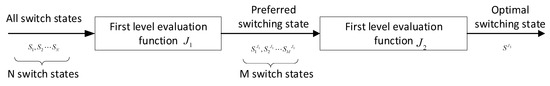
Figure 3.
Block diagram of the sequential model predictive control system.
Sequential model predictive control initially filters the finite set of system switch states (N in total) in the first step based on the first-level cost function. This selection yields M preferred switch states that minimize the first-level cost function. Subsequently, these M preferred switch states are used as inputs for the second-level cost function in the second step, ultimately identifying the optimal switch state that aligns with the system control objectives. This strategy emphasizes the priority order during the control process, with the first-level cost function addressing the primary control objective, whereas the second-level cost function is designed based on the secondary control objectives.
In this context, the first-level cost function is designed to achieve the control objective of mitigating fluctuations in active or reactive power and the second-level cost function aims to reduce DC bus voltage fluctuations under offshore wind turbine power fluctuations and fault conditions.
First-level cost function:
where and are the power prediction values at time (k + 1) and and represent the power reference values at moment (k + 1).
Second-level cost function:
where represents the AC voltage value of the converter station under the selected preferred switch states from the first-level cost function.
Figure 4 illustrates the proposed sequential model predictive control algorithm workflow:
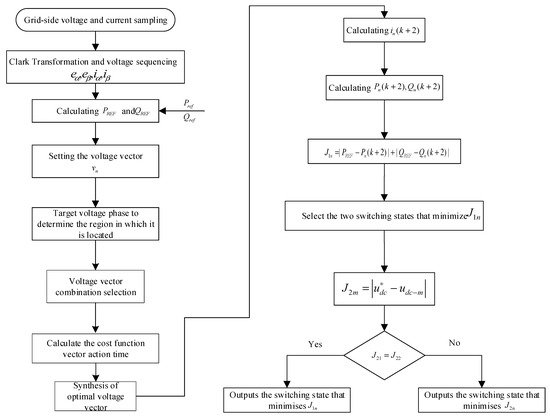
Figure 4.
Flowchart of the sequential model predictive control algorithm.
- Obtain grid-side electromotive force and AC-side current through system sampling and, consequently, acquire system power reference values.
- Determine the region where the target voltage vector resides and select two adjacent non-zero vectors and one zero vector.
- Calculate the action time for each vector and synthesize the virtual voltage control vector.
- Successively predict the system power at time (k + 1) corresponding to all switch states and input them into the first-level cost function . Choose the two switch states that minimize it as preferred switch states.
- If , select the switch state corresponding to as the optimal switch state. Otherwise, choose the switch state corresponding to the smaller value between and as the optimal switch state.
3.2. Three-Vector Control
Traditional model predictive control begins the control process at time k and subsequently completes a series of operations, including AD sampling, electrical signal Clark transformation, power prediction, and the traversal and optimization of the cost function. This sequence of control operations cannot be executed instantaneously. Additionally, as the number of control objectives increases, the computational workload substantially rises. The control process introduces a delay for one control cycle, resulting in a significant control error. Furthermore, traditional model predictive control employs only one voltage vector for control within a single period, often leading to discrepancies with actual vectors and, as a result, imprecise tracking. This discrepancy results in substantial power fluctuations. Therefore, in this paper, three-vector model predictive control is adopted to achieve error-free operation without the need for traversal and optimization, significantly reducing errors during the control process.
The control strategy of the three vectors is to achieve the optimal combination of two adjacent non-zero vectors and one zero vector to control the switching devices and reach the system’s optimal state. By using the method of space voltage vectors, the optimal voltage vector combination can be obtained. It only requires accurate determination of the region where the voltage vector is located. Then, based on the space voltage vector, the drive signals for the six switches can be determined. This represents an improvement from model predictive control with errors to model predictive control without errors.
From Figure 5, it can be observed that when the target voltage is u1, in the case of the traditional control strategy, the voltage control vector U1 closest to u1 should be used, resulting in a control error of e2. On the other hand, when employing the three-vector control strategy, the nearest non-zero vectors, U1 and U2, and a zero vector are combined to form a virtual voltage vector for control, resulting in zero control error.
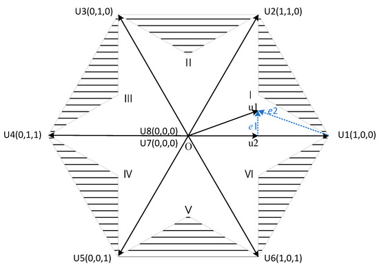
Figure 5.
Voltage vector space.
Taking the first sector as an example, the control error is given by:
where and are the αβ components of the synthesized virtual voltage vectors, j = I, II, III, IV.
Assuming that the target voltage vector is in sector I at this time, define the inverse of the cost function of the zero vector of the synthetic virtual voltage vector to be and the action time to be , the inverse of the cost function of the voltage vector to be , and the action time to be and the inverse of the cost function of the voltage vector to be , and the action time to be .
The action times of each voltage vector are inversely proportional to the cost functions, that is:
3.3. Active-Disturbance-Rejection-Based Model Predictive Control
Traditional model predictive control for tracking the DC-side power reference value uses conventional PID control. However, when the rectifier changes load, the system experiences a long transient operation time. To expedite the system’s return to a stable state, this paper adopts ADRC to track the DC-side voltage reference value. The Active Disturbance Rejection Control (ADRC) controller is derived from PID and offers several advantages, such as minimal steady-state error, short settling time, and independence from system models. It effectively mitigates the impact of unpredictable disturbances on system performance, endowing the system with self-disturbance rejection capabilities and enhancing robustness. The ESO (Extended State Observer) identifies unknown system models and total disturbances and subsequently adds disturbance compensation to the input signal, enabling the system to acquire self-disturbance rejection capabilities. The ESO is the most critical component of ADRC, and the selection of its parameters is crucial. The following sections will provide a detailed explanation of ESO parameter design.
Because the rectifier operates under unit power factor conditions, the system maintains a balance between AC-side and DC-side power, resulting in the system power model as:
In the equation, , , , and represent the system-side electromotive force and current in the dq coordinate system, P and represent the power on the AC and DC sides, C represents the capacitance on the DC side, and represents the resistance on the DC side.
Since the system operates under unit power factor conditions, simplifying yields:
Let y = , , , :
Based on the above equation, this paper combines internal system parameters and external load disturbances into the total disturbance term of the system. The system only requires a first-order ADRC to achieve the desired target tracking control. First, the ESO parameter design is carried out and from the formula we have:
where and are estimates of x and y, A, B, and C are system state equation coefficient matrices, and L is the parameter matrix for system disturbances . Since the power model in this paper corresponds to a first-order system, the ESO used in this paper only requires a first-order extended state observer. The ESO parameter matrix is given as:
Using the characteristic equation of the parameter matrix, we can solve for and :
Typically, the poles are kept at the observer bandwidth:
From this, we obtain: , .
In ADRC, the signal, after passing through TD, combines with the reference value that has a transient process and the signal is compensated dynamically by ESO to form a series control system. This paper deals with a first-order system, so the ADRC and ESO used in this paper are both first-order systems. Therefore, state error feedback control here only requires a relatively simple proportional control, akin to PD control.
The controller state equation is:
where , is the current closed-loop bandwidth. Figure 6 depicts the flowchart of the active disturbance rejection control.
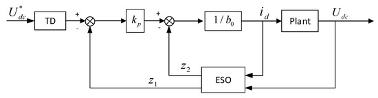
Figure 6.
Flowchart of active disturbance rejection control.
Combining the aforementioned sections, the proposed control process of the three-vector sequential model predictive control in terms of active disturbance rejection is depicted as shown in Figure 7. Initially, measurements of the electric current from the offshore wind farm are obtained. Subsequently, voltage vectors are selected and computed, synthesizing the ideal voltage vector. Notably, the traditional MPC’s power reference value tracker using PID control is substituted with ADRC control. These input components are integrated into the predictive model and selection is conducted through a dual-layer cast function. Ultimately, the ideal switching signals are obtained for the control of the system.
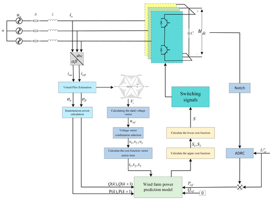
Figure 7.
The three-vector sequential model predictive control in terms of active disturbance rejection.
4. Discussion
To verify the effectiveness of the proposed three-vector ADRC-SMPC, a simulation model was established in MATLAB/Simulink. Electrical response curves for various electrical objectives were compared for offshore wind farms connected to a double-ended flexible DC transmission network under different operating conditions using both traditional MPC and three-vector ADRC-SMPC control. The simulation parameters are shown in Table 2.
Table 2.
System Simulation Parameters.
Case 1: Normal working conditions
Under normal operating conditions, the DC bus voltage is stable at 100 kV and the reactive power is 0 VAR. The control results for the three-vector ADRC-MPC and the three-vector ADRC-SMPC with DC bus voltage added to the value function are shown in Figure 8 and Figure 9. The outcomes reveal that both the three-vector ADRC-MPC and the sequential three-vector ADRC-MPC effectively manage voltage and power. Active power is consistently controlled at 300 MW, whereas the reactive power remains around 0 var. However, the sequential three-vector ADRC-MPC, including the direct current bus voltage in the cost function, results in a narrower fluctuation range in the direct current bus voltage during control, thereby exhibiting superior control effectiveness.
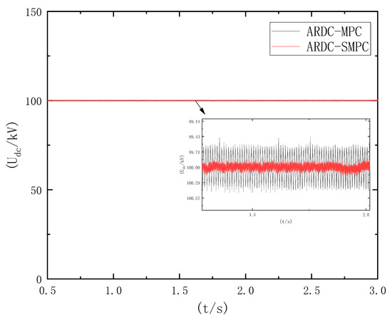
Figure 8.
Voltage response curves for two control modes.
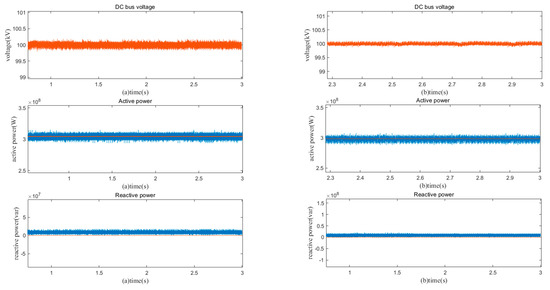
Figure 9.
Response curves under normal operating conditions under both controls: (a) ADRC-MPC and (b) ADRC-SMPC (The graph shows the given values in orange, the actual values in blue).
Case 2: Sudden voltage drop in offshore wind farm due to fault
Under normal operating conditions, the DC bus voltage remains stable at 100 kV. However, at t = 1 s, a fault occurs in the offshore wind farm, causing a sudden drop in the wind turbine output voltage. The fault is cleared at t = 1.1 s. The simulation results for traditional MPC and the control proposed in this paper are shown in the Figure 10 and Figure 11. The results indicate that when faults occur in the offshore wind farm, changes in the system model parameters result in the suboptimal performance of traditional MPC control. During faults, there is a significant fluctuation in the direct current bus, reaching up to 30% in voltage overlimit. Both active and reactive power experience considerable abrupt changes. After fault clearance, the return to a stable state is sluggish, requiring 0.5 s to reach a new steady state. The fault recovery capability is weak in this scenario.
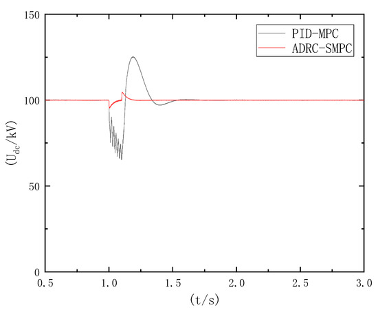
Figure 10.
Voltage response curves for two control modes during sudden drop in output voltage.
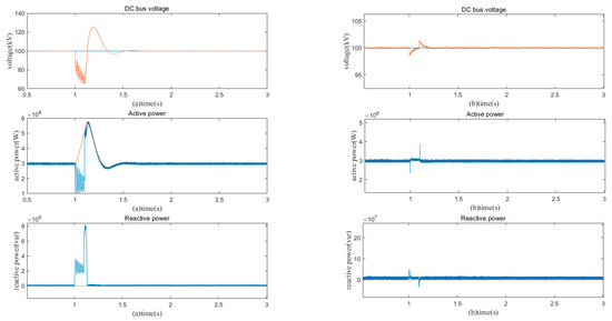
Figure 11.
Response curves of offshore wind farms during voltage dips due to faults under two controls: (a) PID-MPC and (b) ADRC-SMPC (The graph shows the given values in orange, the actual values in blue).
In contrast, the proposed three-vector ADRC-MPC demonstrates superior control performance. It maintains minimal fluctuations in the direct current bus during faults, with voltage overlimit peaking at only 2%. Additionally, the abrupt changes in active and reactive power during faults are significantly smaller, around 30% of those observed under traditional MPC control. The recovery to stability after a fault is rapid and achieved in just 0.1 s, indicating a strong fault recovery capability.
Case 3: Sudden increase in DC bus voltage
Under normal operating conditions, the DC bus voltage remains stable at 100 kV. However, at t = 1.5 s, there is a sudden increase in voltage to 114 kV. The simulation results for traditional MPC and three-vector ADRC-MPC control are shown in Figure 12 and Figure 13. The results indicate that when there is a sudden increase in DC bus voltage, the three-vector ADRC-MPC reaches the new stable value faster than traditional MPC by approximately 0.1 s. Under the proposed three-vector ADRC-MPC control, neither voltage nor power exhibited overshoot during the transition to the new steady state, resulting in a smoother transient response. Moreover, the three-vector ADRC-MPC control demonstrated minimal abrupt changes in power and shorter transient times in controlling power.
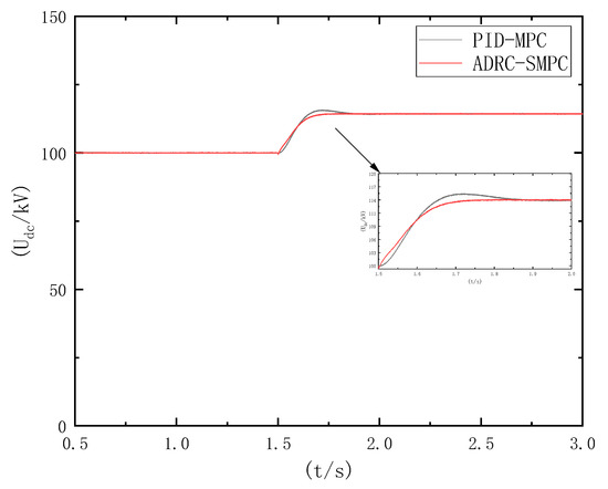
Figure 12.
Voltage response curves under two control modes during DC bus voltage surge.
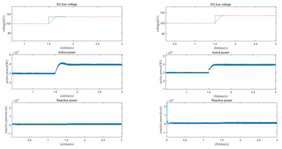
Figure 13.
Response curves for DC bus voltage surge under two controls: (a) PID-MPC and (b) ADRC-SMPC (The graph shows the given values in orange, the actual values in blue).
Case 4: Three-phase short circuit fault at the wind farm sending end
Under normal operating conditions, the DC bus voltage remains stable at 100 kV. When t = 1 s, a three-phase symmetrical fault occurs at the wind-farm-sending-end connection point. It is cleared at t = 1.1 s. The simulation results for traditional MPC and three-vector ADRC-MPC are shown in Figure 14 and Figure 15. The results indicate that after the three-phase short circuit fault, three-vector ADRC-MPC achieves faster stabilization in both DC bus voltage and active power control compared with traditional MPC by approximately 0.15 s. Once stabilized, the voltage and active power fluctuations are also smaller, demonstrating a better fault recovery capability.
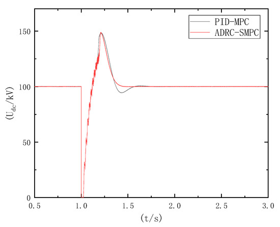
Figure 14.
Voltage response curves under two control modes in the case of a three-phase short-circuit fault at the wind farm terminal.
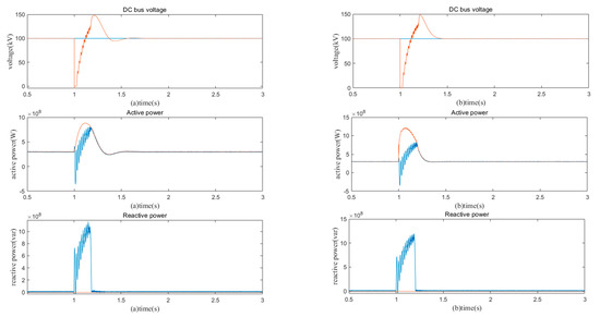
Figure 15.
Power response curves under two control modes in the case of a three-phase short-circuit fault at the wind farm end: (a) PID-MPC and (b) ADRC-SMPC (The graph shows the given values in orange, the actual values in blue).
Case 5: Load resistance change
Under normal operating conditions, the direct current (DC) bus voltage stabilizes at 100 kV. At t = 1 s, when the load resistance decreases to 80% of its original value, the system enters a transient state. The simulated results of traditional MPC and the proposed three-vector ADRC-SMPC control are depicted in Figure 16 and Figure 17. The steady-state performance of both methods is relatively consistent. However, a noticeable difference arises after 1 s. When employing the three-vector ADRC-SMPC control proposed in this study, the abrupt variation in the direct current bus voltage is markedly smaller compared with traditional MPC. Additionally, the time required to restore stability is significantly reduced, allowing the system to rapidly return to a steady-state operation, thereby achieving the objective of self-disturbance rejection.
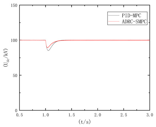
Figure 16.
Voltage response curves under two control modes when the load resistance changes.
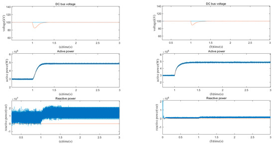
Figure 17.
Response curves under two controls when the load resistance is varied: (a) PID-MPC and (b) ADRC-SMPC (The graph shows the given values in orange, the actual values in blue).
5. Conclusions
The paper introduces a novel approach called the three-vector ADRC-SMPC control method that replaces the conventional PID controller used in the traditional MPC control for reference value control with an ADRC controller. This method effectively suppresses the effects caused by system parameter changes, endowing the system with disturbance rejection capabilities. Additionally, by incorporating the sequential MPC control concept, it not only achieves multi-objective control but also overcomes the challenges associated with selecting weight coefficients.
Under normal operating conditions or during faults that do not significantly alter system parameters, there is little difference in the control performance between traditional PID-MPC and the proposed three-vector ADRC-SMPC. However, the three-vector ADRC-SMPC approach introduced here exhibits a significantly reduced time to restore stability and a superior ability to recover from faults. The addition of sequential MPC in the value function results in a further reduction in bus voltage fluctuations. Nevertheless, when faults occur that induce changes in system parameters, traditional PID-MPC control proves to be ineffective. In contrast, the three-vector ADRC-SMPC control demonstrates minimal abrupt changes, superior control performance, shorter control duration, and a rapid return to steady-state operation after disturbances, successfully achieving the objective of self-disturbance rejection.
Author Contributions
Conceptualization, J.L.; methodology, J.L.; software, J.L.; validation, J.L., Y.S. and J.W.; formal analysis, J.L.; investigation, Q.Z.; resources, H.Z. and H.W.; data curation, Y.S.; writing—original draft preparation, J.L.; writing—review and editing, J.L.; supervision, J.W.; project administration, J.W. and H.W.; funding acquisition, J.W. All authors have read and agreed to the published version of the manuscript.
Funding
This research was funded by Key Laboratory in Xinjiang Uygur Autonomous Region of China (2023D04071), and National Natural Science Foundation of China (52167016). The project was supported by the Key Research and Development Project of Xinjiang Uygur Autonomous Region (2022B01020-3).
Institutional Review Board Statement
Not applicable.
Informed Consent Statement
Not applicable.
Data Availability Statement
Data are contained within the article.
Conflicts of Interest
Author Qiang Zhang was employed by the company State Grid Xinjiang Integrated Energy Service Company The remaining authors declare that the research was conducted in the absence of any commercial or financial relationships that could be construed as a potential conflict of interest.
Nomenclature
| MPC | Model Predictive Control |
| ADRC | Active Disturbance Rejection Control |
| FCS-MPC | Finite Control Set Model Predictive Control |
| HVDC | High-voltage direct current |
| WF-VSC | Wind-Farm-Side Voltage-Source Converter |
| GS-VSC | Grid-Side Voltage-Source Converter |
| SMPC | Sequential Model Predictive Control |
| ESO | Extended State Observer |
| NPC | Neutral Point Clamped |
References
- Yuan, X.; Su, C.W.; Umar, M.; Shao, X.; Lobonţ, O.R. The race to zero emissions: Can renewable energy be the path to carbon neutrality? J. Environ. Manag. 2022, 308, 114648. [Google Scholar] [CrossRef] [PubMed]
- Schulz-Stellenfleth, J.; She, J.; Blauw, A.; Laakso, L.; Mourre, B.; Wehde, H. Fit-for-Purpose Information for Offshore Wind Farming Applications—Part-II: Gap Analysis and Recommendations. J. Mar. Sci. Eng. 2023, 11, 1817. [Google Scholar] [CrossRef]
- Carayannis, E.G.; Ilinova, A.; Cherepovitsyn, A. The future of energy and the case of the arctic offshore: The role of strategic management. J. Mar. Sci. Eng. 2021, 9, 134. [Google Scholar] [CrossRef]
- Yang, B.; Liu, B.; Zhou, H.; Wang, J.; Yao, W.; Wu, S.; Shu, H.; Ren, Y. A critical survey of technologies of large offshore wind farm integration: Summary, advances, and perspectives. Prot. Control. Mod. Power Syst. 2022, 7, 17. [Google Scholar] [CrossRef]
- Lakshmanan, P.; Sun, R.; Liang, J. Electrical collection systems for offshore wind farms: A review. CSEE J. Power Energy Syst. 2021, 7, 1078–1092. [Google Scholar]
- Blasco-Gimenez, R.; Ano-Villalba, S.; Rodríguez-D’Derlée, J.; Morant, F.; Bernal-Perez, S. Distributed voltage and frequency control of offshore wind farms connected with a diode-based HVdc link. IEEE Trans. Power Electron. 2010, 25, 3095–3105. [Google Scholar] [CrossRef]
- Blasco-Gimenez, R.; Ano-Villalba, S.; Rodriguez-D’Derlee, J.; Bernal-Perez, S.; Morant, F. Diode-based HVdc link for the connection of large offshore wind farms. IEEE Trans. Energy Convers. 2011, 26, 615–626. [Google Scholar] [CrossRef]
- Blasco-Gimenez, R.; Aparicio, N.; Añó-Villalba, S.; Bernal-Perez, S. LCC-HVDC connection of offshore wind farms with reduced filter banks. IEEE Trans. Ind. Electron. 2012, 60, 2372–2380. [Google Scholar] [CrossRef]
- Yu, L.; Li, R.; Xu, L. Distributed PLL-based control of offshore wind turbines connected with diode-rectifier-based HVDC systems. IEEE Trans. Power Deliv. 2017, 33, 1328–1336. [Google Scholar] [CrossRef]
- Wang, F.; Zhang, Z.; Mei, X.; Rodríguez, J.; Kennel, R. Advanced control strategies of induction machine: Field oriented control, direct torque control and model predictive control. Energies 2018, 11, 120. [Google Scholar] [CrossRef]
- Zhang, Z.; Kennel, R. Direct model predictive control of three-level NPC back-to-back power converter PMSG wind turbine systems under unbalanced grid. In Proceedings of the 2015 IEEE International Symposium on Predictive Control of Electrical Drives and Power Electronics (PRECEDE), Valparaiso, Chile, 5–6 October 2015. [Google Scholar]
- Zhang, Z.; Hackl, C.; Abdelrahem, M.; Kennel, R. Voltage sensorless direct model predictive control of 3L-NPC back-to-back power converter PMSG wind turbine systems with fast dynamics. Tc Clarke Trans. 2016, 3, 2. [Google Scholar]
- Taheri, A.; Zhalebaghi, M.H. A new model predictive control algorithm by reducing the computing time of cost function minimization for NPC inverter in three-phase power grids. Isa Trans. 2017, 71, 391–402. [Google Scholar] [CrossRef] [PubMed]
- Zhang, X.; Tan, G.; Xia, T.; Wang, Q.; Wu, X. Optimized switching finite control set model predictive control of NPC single-phase three-level rectifiers. IEEE Trans. Power Electron. 2020, 35, 10097–10108. [Google Scholar] [CrossRef]
- Wang, Q.; Yu, H.; Li, C.; Lang, X.; Yeoh, S.S.; Yang, T.; Rivera, M.; Bozhko, S.; Wheeler, P. A low-complexity optimal switching time-modulated model-predictive control for PMSM with three-level NPC converter. IEEE Trans. Transp. Electrif. 2020, 6, 1188–1198. [Google Scholar] [CrossRef]
- Zhang, Z.; Li, Z.; Kazmierkowski, M.P.; Rodriguez, J.; Kennel, R. Robust predictive control of three-level NPC back-to-back power converter PMSG wind turbine systems with revised predictions. IEEE Trans. Power Electron. 2018, 33, 9588–9598. [Google Scholar] [CrossRef]
- Singh, V.K.; Tripathi, R.N.; Hanamoto, T. HIL co-simulation of finite set-model predictive control using FPGA for a three-phase VSI system. Energies 2018, 11, 909. [Google Scholar] [CrossRef]
- Zhang, J.-Z.; Sun, T.; Wang, F.; Rodriguez, J.; Kennel, R. A computationally efficient quasi-centralized DMPC for back-to-back converter PMSG wind turbine systems without DC-link tracking errors. IEEE Trans. Ind. Electron. 2016, 63, 6160–6171. [Google Scholar] [CrossRef]
- Zhang, Z.; Wang, F.; Wang, J.; Rodríguez, J.; Kennel, R. Nonlinear direct control for three-level NPC back-to-back converter PMSG wind turbine systems: Experimental assessment with FPGA. IEEE Trans. Ind. Inform. 2017, 13, 1172–1183. [Google Scholar] [CrossRef]
- Zhang, Z.; Fang, H.; Gao, F.; Rodriguez, J.; Kennel, R. Multiple-vector model predictive power control for grid-tied wind turbine system with enhanced steady-state control performance. IEEE Trans. Ind. Electron. 2017, 64, 6287–6298. [Google Scholar] [CrossRef]
- Lyu, Z.; Wu, X.; Gao, J.; Tan, G. An improved finite-control-set model predictive current control for IPMSM under model parameter mismatches. Energies 2021, 14, 6342. [Google Scholar] [CrossRef]
- Liu, X.; Zhou, L.; Wang, J.; Gao, X.; Li, Z.; Zhang, Z. Robust Predictive Current Control of Permanent-Magnet Synchronous Motors with Newly Designed Cost Function. IEEE Trans. Power Electron. 2020, 35, 10778–10788. [Google Scholar] [CrossRef]
- Lin, C.-K.; Yu, J.-T.; Lai, Y.-S.; Yu, H.-C. Improved Model-Free Predictive Current Control for Synchronous Reluctance Motor Drives. IEEE Trans. Ind. Electron. 2016, 63, 3942–3953. [Google Scholar] [CrossRef]
- Carlet, P.G.; Tinazzi, F.; Bolognani, S.; Zigliotto, M. An Effective Model-Free Predictive Current Control for Synchronous Reluctance Motor Drives. IEEE Trans. Ind. Appl. 2019, 55, 3781–3790. [Google Scholar] [CrossRef]
Disclaimer/Publisher’s Note: The statements, opinions and data contained in all publications are solely those of the individual author(s) and contributor(s) and not of MDPI and/or the editor(s). MDPI and/or the editor(s) disclaim responsibility for any injury to people or property resulting from any ideas, methods, instructions or products referred to in the content. |
© 2023 by the authors. Licensee MDPI, Basel, Switzerland. This article is an open access article distributed under the terms and conditions of the Creative Commons Attribution (CC BY) license (https://creativecommons.org/licenses/by/4.0/).