Article

Underwater Geomagnetic Localization Based on Adaptive Fission Particle-Matching Technology

1
National Innovation Institute of Defense Technology, Beijing 100071, China
2
Hubei Key Laboratory of Marine Electromagnetic Detection and Control, Wuhan 430064, China
3
Science and Technology on Underwater Vehicles Laboratory, Harbin Engineering University, Harbin 150001, China
4
Wuhan Second Ship Design and Research Institute, Wuhan 430064, China
*
Author to whom correspondence should be addressed.
J. Mar. Sci. Eng. 2023, 11(9), 1739; https://doi.org/10.3390/jmse11091739
Submission received: 22 July 2023 / Revised: 31 August 2023 / Accepted: 31 August 2023 / Published: 4 September 2023

Abstract

:
The geomagnetic field constitutes a massive fingerprint database, and its unique structure provides potential position correction information. In recent years, particle filter technology has received more attention in the context of robot navigation. However, particle degradation and impoverishment have constrained navigation systems’ performance. This paper transforms particle filtering into a particle-matching positioning problem and proposes a geomagnetic localization method based on an adaptive fission particle filter. This method employs particle-filtering technology to construct a geomagnetic matching positioning model. Through adaptive particle fission and sampling, the problem of particle degradation and impoverishment in traditional particle filtering is solved, resulting in improved geomagnetic matching positioning accuracy. Finally, the proposed method was tested in a sea trial, and the results show that the proposed method has a lower positioning error than traditional particle-filtering and intelligent particle-filtering algorithms. Under geomagnetic map conditions, an average positioning accuracy of about 546.44 m is achieved.

1. Introduction

Navigation and positioning systems are the core technologies of autonomous underwater vehicles (AUVs) [1,2]. However, due to the rapid attenuation of Global Positioning System (GPS) signals in water, autonomous underwater robots cannot rely on GPSs for accurate navigation and positioning [3,4]. Inertial navigation systems (INSs) are currently the main forms of navigation equipment employed in underwater vehicles [5]. However, due to the continuous accumulation of measurement errors from gyroscopes and accelerometers over time, inertial navigation eventually leads to the divergence of positioning errors [6]. Effective positioning correction methods are still a popular and challenging topic in the field of underwater navigation [7].
Geomagnetic fields can provide pose correction references for underwater navigation systems. Inspired by biological geomagnetic localization, researchers have developed a series of geomagnetic positioning methods [8,9,10,11], such as geomagnetic contour matching algorithms (MAGCOMs) [12], iterative closest contours point (ICCP) [13], simultaneous localization and mapping (SLAM) of the geomagnetic field [14,15], and multi-parameter search without a magnetic map [16]. Wu proposed using interval knowledge of geomagnetic field measurements to overcome the uncertainty in measurement for practical applications of geomagnetic positioning, and underwater experiments showed that the root-mean-square error of the proposed method reached 139.3 m [17]. Li et al. proposed a dual-feature matching algorithm combining geomagnetic total intensity and its gradient to solve problems such as poor matching accuracy in areas with low geomagnetic roughness using only magnetic field total intensity as a feature. The results of a simulation experiment showed that compared with a traditional correlation matching algorithm, the positioning accuracy of the proposed algorithm could reach within 20 m [18]. A MAGCOM generally requires vehicles to accumulate a segment of trajectory and compares the correlation between the magnetic survey sequence and the magnetic map sequence in the matching area to obtain accurate position information. Compared with MAGCOMs, the ICCP algorithm enhances the ability of a rotation search based on a translational search, thereby improving the algorithm’s accuracy. These methods have been effective with regard to geomagnetic positioning to some extent. However, the sparsity of geomagnetic characteristics in marine environments often leads to problems such as low effective matching rates for these algorithms within the preset matching area. Expanding the search and matching range precipitates higher computational resource consumption.
In recent years, terrain matching navigation based on particle-filtering technology has been applied [19,20]. The corresponding algorithms used in this process introduce the idea of probability estimation, which can effectively compensate for the shortcomings of geomagnetic matching algorithms based on correlation measurement. Among these algorithms, the particle-filtering method based on Bayesian estimation has shown strong performance in processing nonlinear problems [21]. Quintas et al. demonstrated that particle filtering is robust in geomagnetic navigation problems [22]. As the iteration process progresses, the impoverishment and degradation of traditional particle-filtering methods lead to particle swarm clustering and the inability to identify the best matching point. Ultimately, an unsatisfactory position correction source was obtained.
To solve the problem of particle degradation and impoverishment, this article proposes an adaptive fission particle-filtering geomagnetic matching localization algorithm. During the execution of particle matching and positioning, the current particles undergo a splitting operation and generate new particles. The newly developed particles are called “offspring” particles, while the original particles are known as “parent” particles. The degree of particle fission is judged based on the particle weight, and it is proposed that the sampling of “offspring” particles should consider both the degree of particle fission of the parent particles and the sampling variance of the “parent” particles. By redefining the sampling of the offspring particles, the distribution of the particle set becomes more reasonable, and the method can be explained in terms of generality, thus improving the probability of obtaining a correct match in geomagnetic positioning. Our contributions can be summarized as follows:
  • Particle-matching technology is employed to realize underwater geomagnetic localization.
  • An adaptive fission particle-filtering algorithm is proposed to solve the problem of particle degeneration and particle impoverishment. Compared with advanced intelligent particle-filtering methods, our method achieves better localization accuracy.
  • The proposed method was tested in a marine environment, and the results show that our proposed geomagnetic localization method can effectively achieve underwater navigation error correction.
The remainder of this paper is organized as follows. Section 2 introduces related works. Section 3 presents the problems and methods. Section 4 describes the experiments. Section 5 draws conclusions from the study.

2. Principle of Geomagnetic Matching Localization

The principle of geomagnetic matching is to store the geomagnetic feature map of the planned trajectory area in advance on a computer. When vehicles navigate to this area, the current geomagnetic field matching feature quantity is obtained in real time through the onboard geomagnetic measuring sensor. Then, the real-time measured geomagnetic data are correlated with the stored geomagnetic map on the computer, and the matched point with a high degree of correlation is selected as the current real position of the vehicles. Afterwards, the geographic coordinates of the position are investigated using the geomagnetic map, providing reliable position information for correcting the navigation trajectory of the vehicles [23].
In this study, a geomagnetic matching localization algorithm based on particle filters was developed, the principles of which are shown in Figure 1. The vehicle employed in this study has a spherical array of magnetic sensors that can obtain real-time measurements of 16-channel, three-axis geomagnetic vector data. Firstly, each magnetometer’s vector magnetic field value is preprocessed to obtain characteristic parameters that can be used for geomagnetic matching calculations. In addition, the vehicle’s dead reckoning (DR) navigation system can provide rough position information. Based on the error setting of the dead reckoning navigation system, the range of particle movement is determined. Afterward, the difference between the map value of the characteristic geomagnetic parameter falling in the corresponding geomagnetic grid and the measurement value is used to update the particle weight. Then, through continuous resampling and other steps, an estimate of the vehicle’s current position is obtained.
Geomagnetic positioning systems based on filtering technology can yield a continuous position output, making them superior to the above positioning methods in terms of real-time performance, and they have received attention from researchers in recent years [24]. Typical methods used in this domain include the geomagnetic/inertial positioning method with Kalman filtering, which is the core method used, and the geomagnetic positioning method with particle filtering [25]. The former draws on the Sandia inertial-geomagnetic navigation system, employs a linearized geomagnetic field model as an observation quantity, and, finally, achieves system’s position or velocity error correction. However, how highly non-linear geomagnetic models are linearized constitutes a crucial factor affecting the accuracy of this method. The latter particle-filtering method based on Bayesian estimation shows strong performance in dealing with non-linear problems, requires low magnetic field measurement accuracy, allows for measurement errors, and has strong robustness. Zhang et al. used particle filtering to achieve underwater terrain matching navigation [26]. In practical applications, as long as the filter does not diverge, the geomagnetic positioning error can always be maintained within a certain range. Therefore, geomagnetic positioning methods based on filtering technology have great developmental potential in future geomagnetic navigation applications.

3. Problems and Methods

3.1. Particle Filter

In a geomagnetic matching navigation system, the state space model can be defined as follows:
x k = f ( x k 1 , u k )
z k = g ( h ( θ ) , x k , v k )
In the Equation (1), x k represents the position outputs of INS, where x k = [ φ k λ k ] T . z k represents the observation vector. h ( θ ) represents the magnetic field intensity at any position on the geomagnetic map. u k and v k represent the state noise and observation noise at time k, respectively, and the two types of noise are independent of each other and follow a Gaussian distribution.
In a particle filter algorithm, assuming that the system process follows an m-order Markov process, the state updating of the system can be achieved based on the posterior probability density recursively derived from observations. However, in reality, it is difficult to directly obtain an accurate posterior probability distribution of a target in a nonlinear system. The importance-sampling technique generates a set of particles x ^ i q ( x ) ( i = 1 , 2 , , N ) via introducing a probability density function with known distribution characteristics and easy sampling characteristics. The choice of the importance probability density function has a significant impact on the accuracy of the algorithm. The detailed theoretical derivation can be found in [27]. Typically, in standard particle-filtering algorithms, the importance density function is set to the prior probability density function, namely
q ( x k i | x 0 : k 1 i , z 1 : k ) = p ( x k | x k 1 i )
where x 0 : k 1 i represents the state variables from time 0 to k − 1, and z 1 : k represents the observed variables from time 1 to k. The recursive update formula for particle weights is simplified as
w k i w k 1 i p ( z k | x k i )
In the problem of magnetic field matching localization, the following must be defined:
p ( z k | x k i ) = 1 2 π τ exp ( ( θ k θ m ) 2 2 τ )
In Equation (5), τ is the variance of the magnetic field measurement error, θ k is the total intensity value of the magnetic field measured by the magnetometer at time k, and θ m is the magnetic map value corresponding to the grid where the particle is located.
Normalize the weights
w ^ k i = w k i i = 1 N w k i
where i = 1 N w i = 1 . Thus, the particles’ posterior probability density and corresponding weights are obtained. However, after several iterations, except for a few particles with large weights, the weights of the remaining particles are so small that they can be ignored. Particle degradation is a common problem faced when using sequential importance-sampling particle filters [28]. In engineering, particle-resampling techniques are commonly used to solve the problem of particle degradation. By adding a resampling calculation step after importance sampling, low-weight particles are eliminated, and high-weight particles are replicated, thereby facilitating the redistribution of particle weights. The three commonly used basic resampling schemes are multinomial resampling, stratified resampling, and systematic resampling. Resampling techniques solve the problem of particle degradation in particle filtering, but they also introduce new problems; replicating only weighted particles reduces the diversity of particles, leading to particle impoverishment [21]. To solve these problems, some adaptive particle-filtering algorithms have been proposed, such as intelligent particle filtering [29] and genetic particle filtering [30].

3.2. Geomagnetic Localization with Adaptive Particle Fission

In response to the problems of particle degradation and impoverishment with respect to traditional particle-filtering algorithms, this paper proposes an adaptive fission particle-filtering geomagnetic matching localization method to correct the dead reckoning error.
In the particle-filtering geomagnetic matching algorithm, the state variables of each particle are set as longitude, latitude, and total magnetic field strength. During initialization, particles are drawn from their prior state distribution and assigned initial weights of w = 1/N, where N is the total number of particles. Then, iterative calculations such as importance sampling are performed. In traditional particle filtering, high-weight particles are copied multiple times during resampling, leading to a need for more diversity among particles. Additionally, continuous iterations cause particles to gather in local areas of the geomagnetic map, resulting in only locally optimal solutions rather than global optimal solutions. As a result, significant positioning errors arise in the wrong matching area.
In the adaptive fission particle-filtering algorithm proposed in this paper, the particles before resampling are employed as “parent” particles, and all “parent” particles generate “offspring” particles after updating their weights. The “parent” particles and “offspring” particles are then mixed, ranked in descending order according to weight, and only the top N particles are retained, while the rest are discarded. This process continuously updates the particle population to enrich its diversity without increasing computational complexity and avoids local optimal solutions due to particle clustering. Assume that the number of “offspring” particles generated by each “parent” particle is m k i .
m k i = round [ N × w k i ] + 2
In the equation above, N is the total number of particles, w k i is the weight of the i-th particle at time k, and round [ x ] is the rounding function. It can be seen that the number of “offspring” particles is determined by the weight of the “parent” particles. High-quality particles with high weights will generate more “offspring”, while low-weight particles can produce at least two “offspring” particles. Therefore, in the iterative calculation process, the diversity of the particles can be maintained.
Next, samples are taken from a Gaussian distribution for the “offspring” particles. The primary purpose of adaptive fission particle filtering is to retain high-weight particles and perturb low-weight particles, moving them to other target areas. Therefore, the sampling of “offspring” particles should satisfy a normal distribution with a mean value of the “parent” particle state and a variance of μ k i , as follows:
x ˜ k i j N ( x k i , μ k i ) , j = [ 1 , m k j ]
Reference [31] defines the particle fission factor a k i as the variance of the samples taken for “offspring” particles.
a k i = 1 ( 1 + exp ( w k i w k avg w k max w k avg ) )
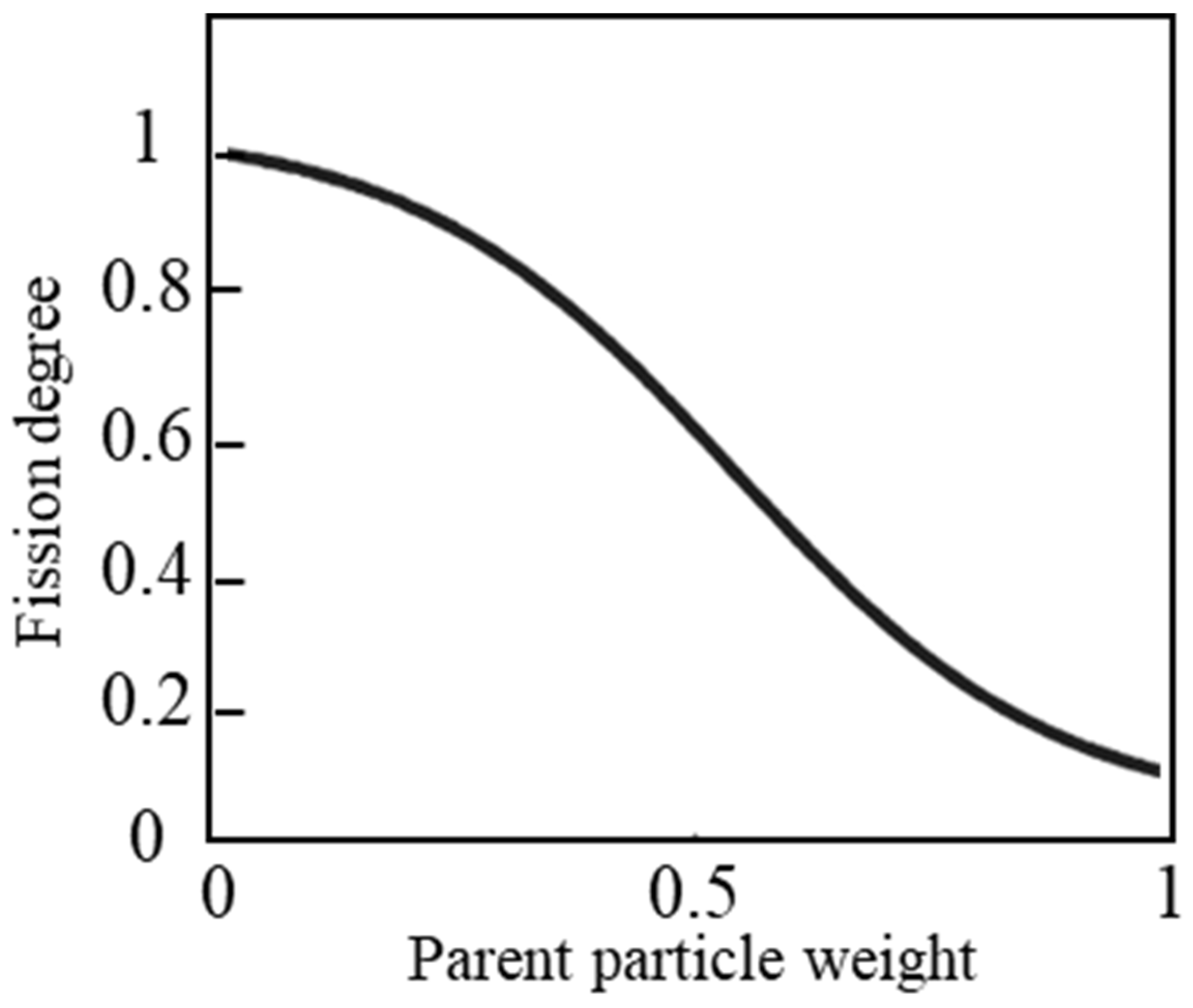
In Equation (9), w k avg and w k max represent the average and maximum weight of the particles at time k . Figure 2 shows the relationship between the weight of the “parent” particles and the fission factor [31]. From Figure 2, it can be seen that “parent” particles with smaller weights have a higher fission degree. However, it is not appropriate to directly use the fission factor as the variance for sampling “offspring” particles. As shown in Figure 2, regardless of whether the “parent” particle has a large or small weight, the sampling variance of the “offspring” particles satisfies 0 < a k i < 1 . For example, if the fission factor is 0.23 and the coordinate of the “parent” particle is (120° E, 30° N), then most of the generated “offspring” particles will be within the range of (120° ± 1.5° E, 30° ± 1.5° N). This distribution of “offspring” particles covers an area of nearly 300 × 300 km, which obviously does not match actual situations. The method proposed in reference [31] is only applicable to an amplitude of seismic wave signals no greater than 10 V at each time interval and has a high degree of contingency.
This paper indicates that the “offspring” particles generated from the fission of the “parent” particles must inherit some characteristics of the “parent” particles. Thus, the sampling of “offspring” particles should be based on the “parent” particles. Assuming that the sampling distribution variance of the “parent” particles is μ k i , then the variance of the sampling of the “offspring” particles should be
σ k i = λ μ k i a k i = λ μ k i ( 1 + exp ( w k i w k avg w k max w k avg ) )
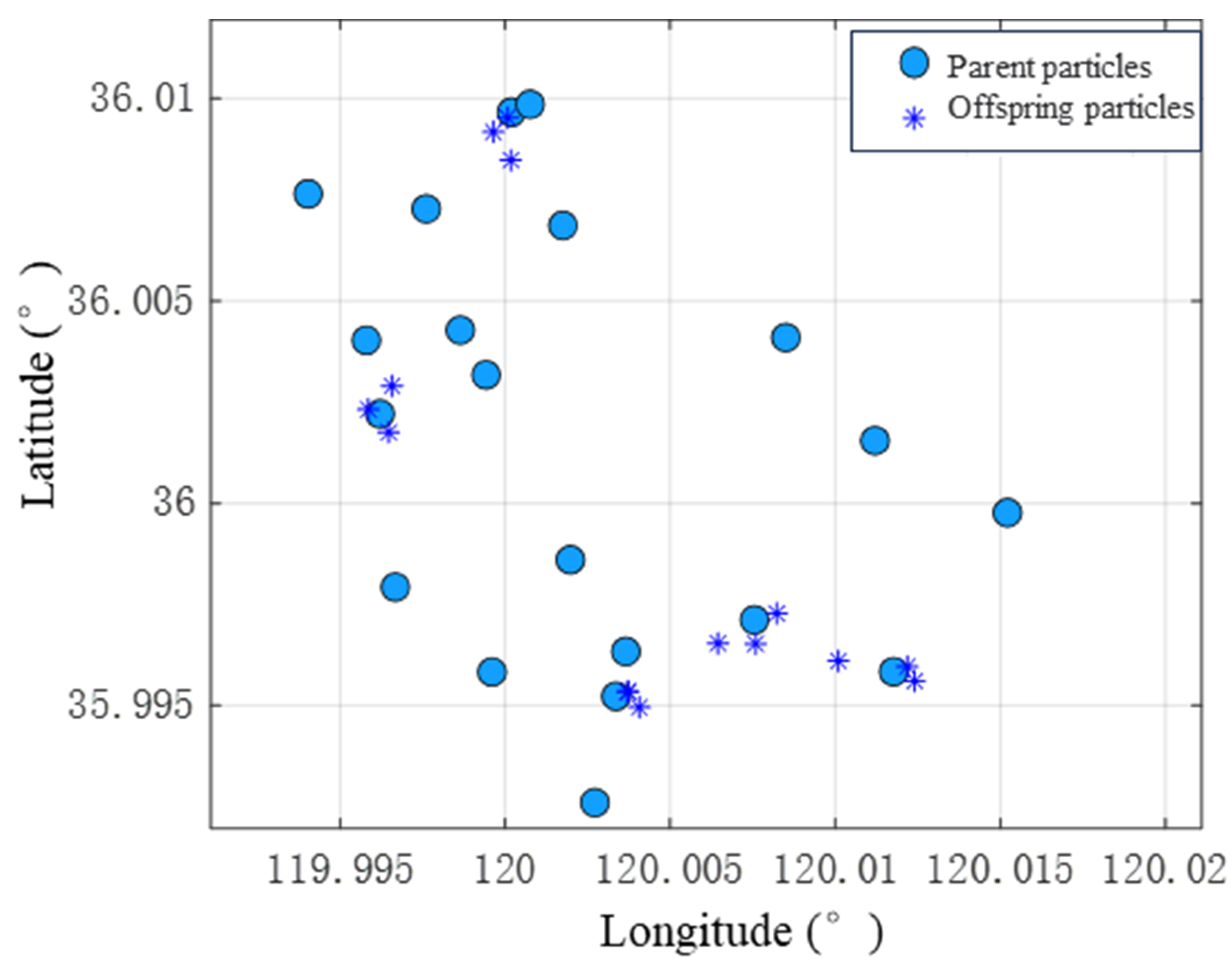
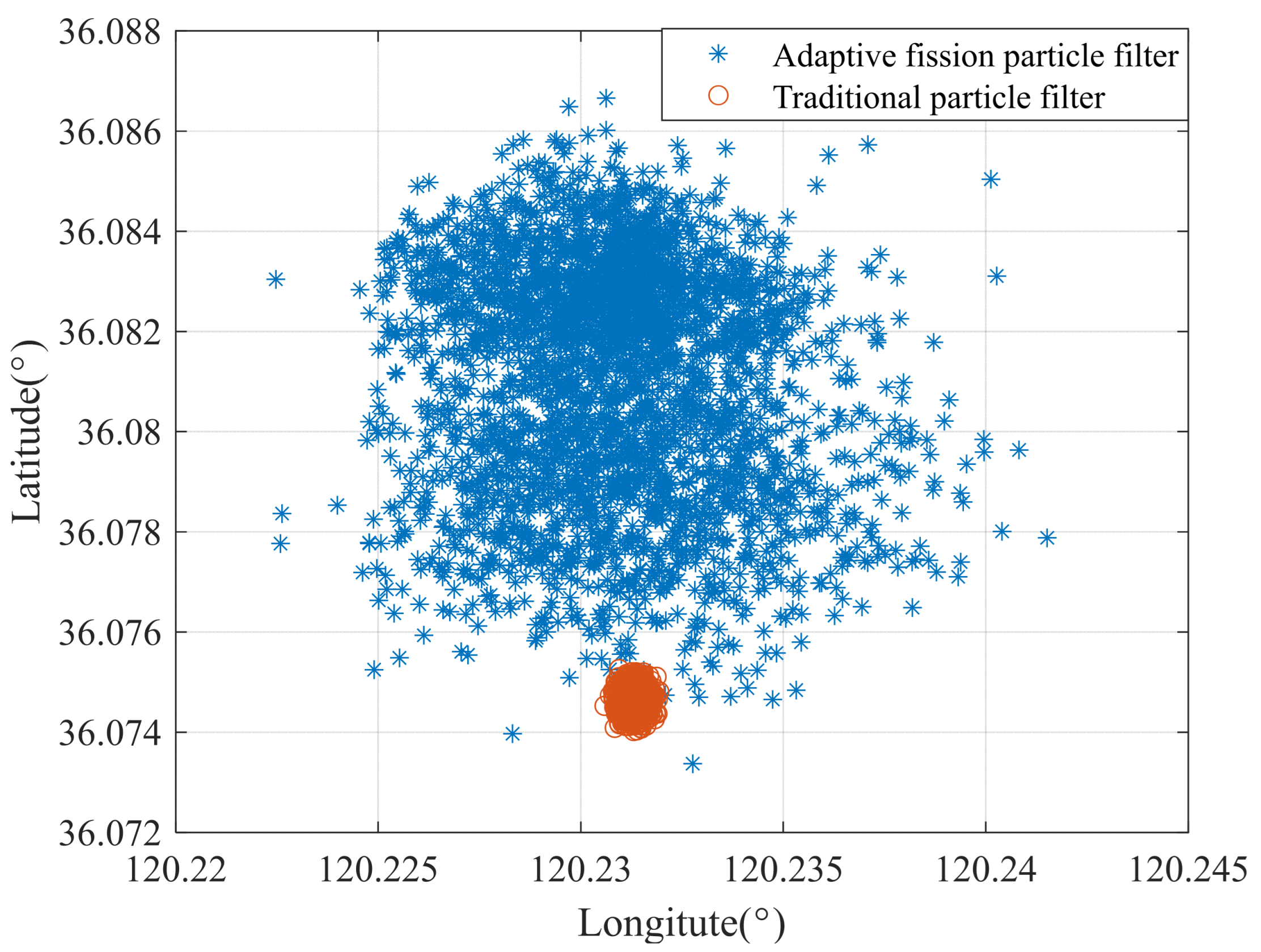
In the equation, λ is the scale factor used to control the range of movement of the “offspring” particles. It is an empirical value, and researchers can set it based on the specific context of the problem being addressed. Equation (10) reflects that, under the consideration of the motion characteristics of the “parent” particles, the “offspring” particles fission adaptively based on the weights of the “parent” particles to obtain better state values. This is achieved by adapting the distribution characteristics of the “parent” particles around the distribution centered on the “parent” particles according to the fission factor size. In Figure 3, the light blue circles represent the “parent” particles, and the blue asterisks represent the “offspring” particles they generate. Each “offspring” particle is distributed around its ‘parent’ particle to explore new optimal solutions. Figure 4 compares the particle diversity between the proposed and traditional particle-filtering methods after 250/417 iterations. It can be seen from Figure 4 that even when the experiment is nearly 60% complete, the particles of the adaptive fission particle-filtering method remain dispersed and have good diversity. In contrast, the particles of the traditional particle-filtering method gather together. Therefore, the proposed adaptive fission particle-filtering method improves the quality of particles and aids the discovery of the best geomagnetic matching point.
The newly generated “offspring” particles x ˜ k i j update their weights according to Equation (4) based on the difference between the geomagnetic field reading values in their state space and the measurement values. Then, the “parent” particles and “offspring” particles constitute the particle set, sorted in descending order according to the weight of particles, and the top particles are selected as the new particle swarm to participate in the following iteration calculation. Finally, the particle weights are normalized, and the optimal matching position is calculated according to Equation (11) based on the states and weights of all particles.
x k = i = 1 N ( x k i w ¯ k i )
The workflow of the adaptive fission particle-filtering geomagnetic matching localization algorithm as Algorithm 1 shows:
Algorithm 1: The adaptive fission particle-filtering geomagnetic matching localization
1.
Initialization: k = 0,
The initialization-state particles x 0 i P ( x 0 ) , i = 1 , 2 , , N are extracted from the prior distribution P ( x 0 ) .
Initialize particle weights w 0 i = 1 / N
2.
Importance sampling: x k i q ( x k | x k 1 i , z 1 : k )
3.
Calculate particle weights w k i w k 1 i p ( z k | x k i ) , p ( z k | x k i ) = 1 2 π τ exp ( ( θ k θ m ) 2 2 τ ) .
4.
Normalize weights w ^ k i = w k i / i = 1 N w k i
5.
Particle fission:
5.1
Calculate the number of offspring m k i = round [ N × w k i ] + 2
5.2
Calculate the state value of the “offspring” particle x ˜ k i j N ( x k i , μ k i ) , j = [ 1 , m k j ]
5.3
Update offspring particle weights, as in step 3.
5.4
Sort all particles by weight in descending order and choose the top N particles to form a new particle swarm for the subsequent iteration calculation { x k i , w ˜ k i } i = 1 N .
6.
Normalize weights w ¯ k i = w ˜ k i / i = 1 N w ˜ k i
7.
Calculate state estimates x k = i = 1 N ( x k i w ¯ k i )

4. Experiments

4.1. Experimental Setup

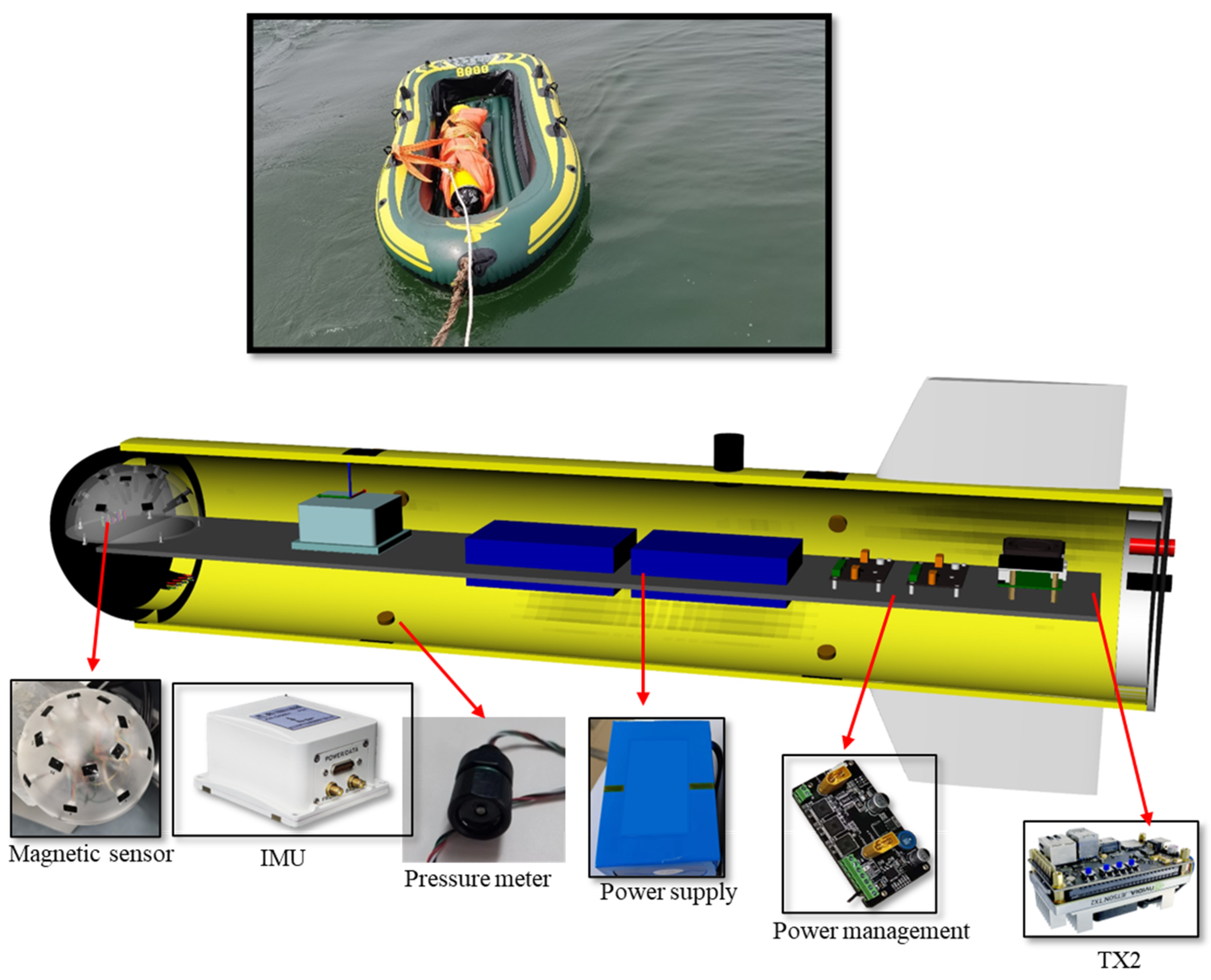
This section reports the results of a sea trial performed to validate the proposed geomagnetic localization method. The vehicle used for the sea trial is shown in Figure 5 [32]. This aluminum alloy vehicle can be divided into a main cabin and a spherical bow. The components of the vehicle can be categorized into a power supply system, a perception system, and a central control system. The power supply system consists of a power supply source and a power management module, which are responsible for providing energy support to the entire system, voltage regulation, and circuit switching. The perception system consists of sensors, including a magnetometer, an inertial measurement unit (IMU), a satellite receiver, and a pressure sensor, and the performance of the corresponding sensors is shown in Table 1. The IMU is an essential sensor of the INS. Together, the INS and the GPS form an integrated navigation unit receiving data from a satellite signal, which provides reference position information for the test system. The central control system consists of an NVIDIA TX2 core board and uses a Linux operating system to read and store data uploaded by various sensors in real time. Each sensor communicates with the central control system through RS232 and USB interfaces.
In this study, two sea trials were conducted in the Jiaozhou Bay area of Qingdao on 22 June and 26 June 2022. The total distance covered in the trial 1 was 9.63 km, and the total distance covered in trial 2 was 14.37 km, for which the average speed was 5 m/s. Data on parameters such as the characteristics of the geomagnetic field, motion acceleration and angular velocity, attitude angle, GPS position, and true heading were collected during the trials. The magnetometer sampling rate was set to 10 Hz during the tests. In comparison, the acceleration and angular velocity sampling rate was set to 100 Hz, and the attitude angle, heading angle, and position data sampling rates were set to 10 Hz. The data from the IMU and magnetometer were saved separately, with a file saved every 10 min. Each data stream was timestamped based on the system read time to facilitate offline data alignment.
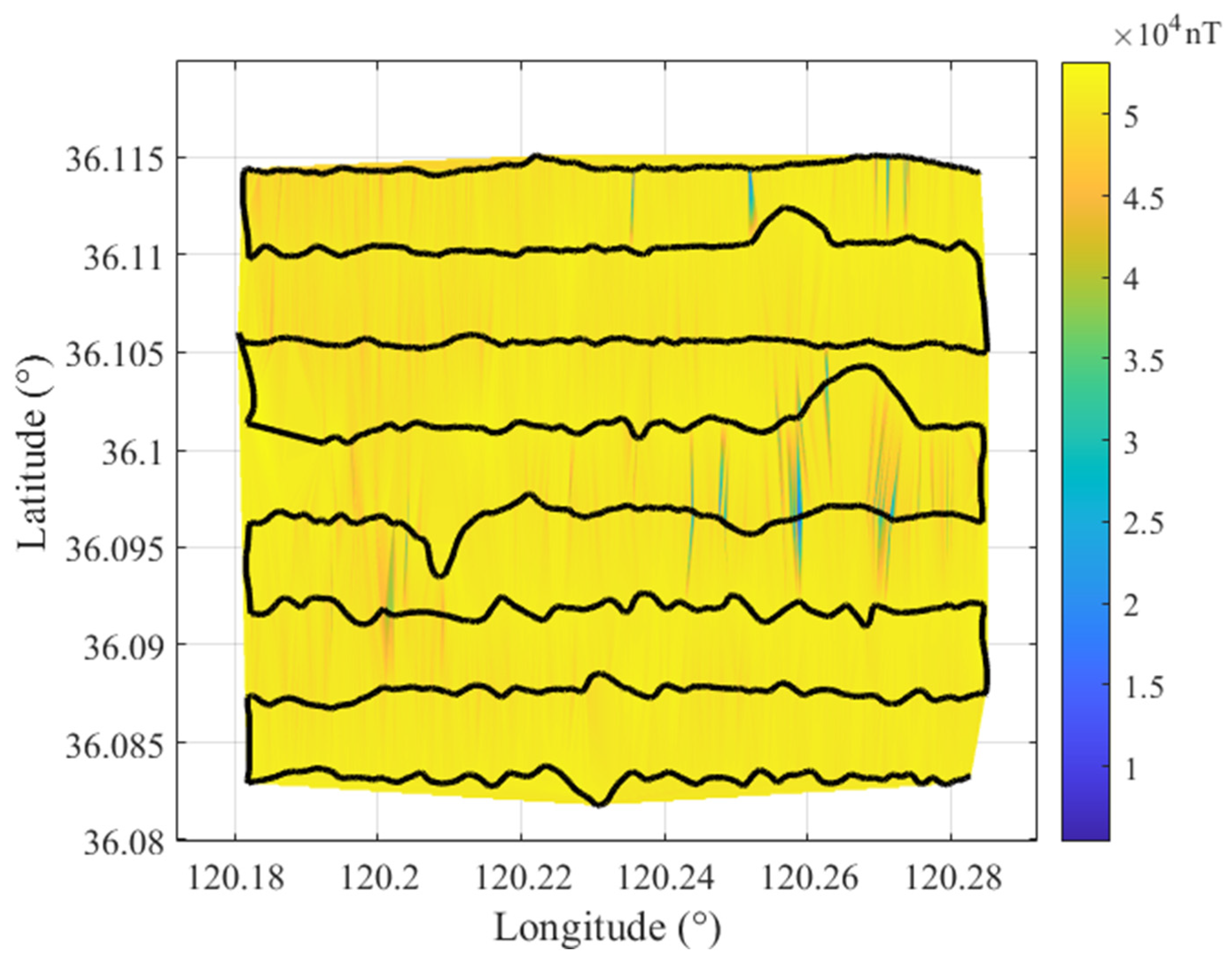
Prior to verifying the performance of the proposed method, we had the vehicle establish a sparse geomagnetic map with dimensions of 9.2 × 3.5 km along the lawn mower trajectory indicated by the black line in Figure 6. The trajectories were spaced approximately 500 m apart in the east–west direction. Then, linear interpolation was used to encrypt the measured geomagnetic data, forming a grid map with a resolution of 50 m. It is well known that the geomagnetic field undergoes long-term variations and short-term diurnal changes [33]. Long-term diurnal variations can be disregarded during geomagnetic navigation, and updating the geomagnetic map every 3–5 years is sufficient. As for short-term diurnal changes, it is advisable to conduct geomagnetic measurement experiments when the geomagnetic field is stable, i.e., around noon [18,34].

4.2. Results and Discussions

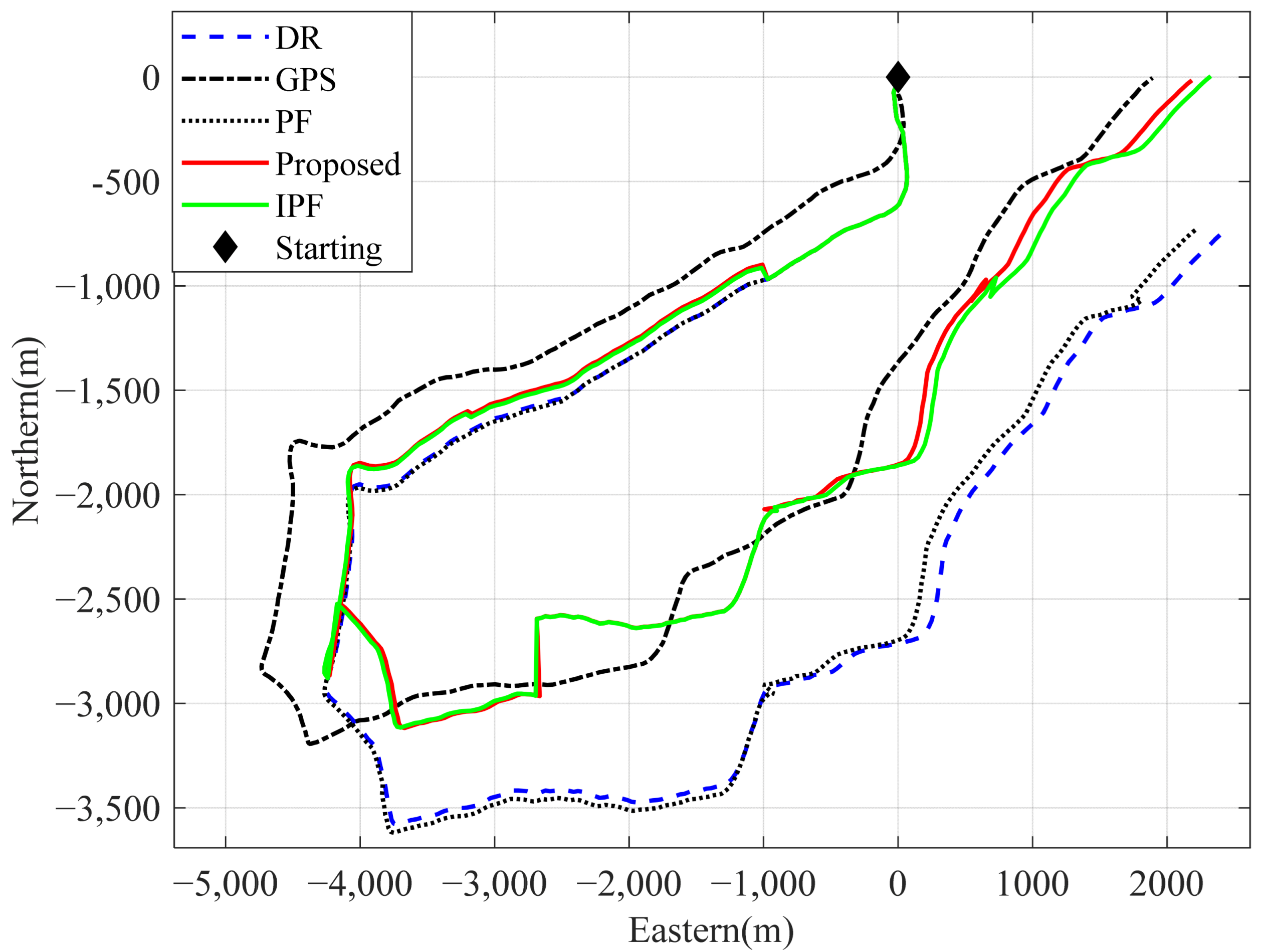
After obtaining the geomagnetic map of the experimental area, the adaptive fission particle filter geomagnetic matching localization method proposed in this section was used to perform further position correction for the dead reckoning results of the vehicle. In the DR algorithm, the motion step and direction of the carrier are estimated based on the information provided by the accelerometer and gyroscope, and the two-dimensional position of the carrier can be calculated using known initial conditions [35].Considering that the geomagnetic field is a large-scale physical field and the magnetic field strength values change very slightly at locations that are close to each other, in cases where the measurement environment is not ideal, the interference noise amplitude may be much larger than the amplitude of geomagnetic field changes, leading to a large number of mismatches. Therefore, in this paper, position correction was performed once when the distance between the front and back exceeded 1 km. During the experiment, the particle sampling variances in the longitudinal and latitudinal directions were set to diag ( 1.6454 × 10 4 , 1.6454 × 10 4 ) , unit in degree2, and τ = 100,000 ; the scaling factor was λ = 0.001 ; and there were 3000 particles. At the initial time, all particles had equal weights, that is, 1/3000. In order to highlight the performance advantages of the adaptive fission particle filter algorithm in relation to geomagnetic positioning, this paper compared it with the traditional particle filter (PF) algorithm and the intelligent particle filter (IPF) algorithm improved by Shen et al. [29]. The results are shown in Figure 7, Figure 8, Figure 9 and Figure 10.
Figure 7 and Figure 8 show that the blue, dashed line represents the dead reckoning system trajectory. In contrast, the black, dotted line is the reference trajectory provided by the GPS installed in the AUV. It can be seen from Figure 7 and Figure 8 that after several successful particle-matching processes, the calculated trajectory is gradually corrected, approaching the true trajectory. The absolute position errors are shown in Figure 9 and Figure 10. It can be seen that the DR algorithm disperses the position errors due to the continuous accumulation of errors. However, PF, IPF, and the proposed method show a stepwise decrease in absolute position error due to the use of the geomagnetic field to correct the DR positioning results. However, for Experiment 2, the correction of the DR navigation results via geomagnetic positioning is less effective than in Experiment 1, particularly for the PF algorithm. This is because the performance of geomagnetic matching positioning algorithms is strongly correlated with geomagnetic features. Most geomagnetic field intensity values are relatively similar in areas with sparse geomagnetic features, making it difficult for particles to match the correct geomagnetic feature points. In addition, as the program progresses, the particle set gradually degenerates into a cluster in the PF algorithm, as shown in Figure 4. At this point, particles only search for matching points in a limited local area, thereby enabling an in improvement in the geomagnetic matching positioning performance of the PF algorithm, which is also the problem this paper aims to solve. In Figure 9, for Test 1, after three consecutive, valid matches, the accumulated position error is constrained, and the corrected trajectory is almost identical to the true trajectory.
In addition, after combining the results of the two tests shown in Figure 9 and Figure 10, it was found that effective geomagnetic positioning occurred in the latter half of the voyage. The error accumulation during navigation calculation in the initial stage was small, resulting in a small distance between the dead-reckoning-indicated position and the true position, and the geomagnetic field strength values at the two positions were close. Therefore, it was difficult for the particles to distinguish the degree of geomagnetic similarity within the exploration range, and most particles eventually had similar weights. As the voyage continued, the accumulated error in the dead reckoning further increased. When there was a clear distinction between the geomagnetic fields at the predicted and true navigation positions, the particles could accurately match the correct position in the motion space through similarity calculations and then perform a correction on the DR navigation results.
Table 2 summarizes the position error results for the three particle-filtering methods in the two experiments. The table shows that the method proposed in this paper outperforms the compared methods in terms of average position error and endpoint error. In the two experiments, the dead reckoning trajectory based on heading and displacement information resulted in absolute position errors of 2391.7 m and 911.15 m, respectively. The adaptive fission particle filter method proposed in this paper can maintain particle diversity throughout the iteration process. It increases the probability of matching the best position, which leads to the geomagnetic positioning results being closer to the true position. After correction using the adaptive fission particle filter geomagnetic positioning method, the absolute position errors at the end of the task were reduced by 98.17% and 67.94%, respectively.
The first two rows of Table 2 are the root-mean-square error and average positioning error, which were obtained by comprehensively considering the positioning error of the entire trajectory. Figure 9 and Figure 10 show that the navigation time of 1600 s in Figure 9 and the performance of the method proposed in this paper before 1500 s in Figure 10 are almost equivalent to those of IPF. Subsequently, due to the better particle diversity of the method proposed in this article, particle matching yielded better matching points than the IPF method, resulting in a significant reduction in positioning error compared to the IPF method (at 1500 s in Figure 10). At around 1800 s, the method proposed in this paper obtained even better matching points based on the original error. So, in the end, the positioning error of the method proposed in this article is smaller than that of the IPF method.
Meanwhile, the geomagnetic matching localization method based on traditional particle filtering reduced the positioning error by 94.23% and 12.76% in the two experiments. The intelligent-particle-filtering-based geomagnetic matching localization method reduced the absolute position errors by 95.02% and 52.45% in the two experiments. The average positioning errors of the proposed method in this paper were 546.44 m for the two experiments. The mean values of the traditional-particle-filtering and intelligent-particle-filtering-based geomagnetic positioning were 628.12 m and 576.85 m, respectively.

5. Conclusions

This paper studied the error accumulation problem in long-duration AUV tasks using the dead reckoning principle by combining displacement and heading. Using sparse geomagnetic maps, a method was proposed to correct the dead reckoning results using the geomagnetic field, thereby achieving the autonomous and covert navigation and positioning of the AUVs in satellite-restrictive environments. This paper proposed an adaptive fission particle-filtering-based geomagnetic positioning method that allows for the creation of “parent” particles before resampling to generate “offspring” particles. The “offspring” particles are sampled according to the fission degree and motion variance of the “parent” particles, ensuring that the particle set maintains diversity during the iteration process. This method solves the problems of particle degradation and impoverishment that occur with traditional particle filtering as the iteration progresses and improves the accuracy of geomagnetic positioning. After sea trials, the proposed adaptive fission particle-filtering-based geomagnetic positioning algorithm effectively corrected the dead reckoning error. The average positioning error after geomagnetic positioning correction was 546.44 m, which is a 41.7% improvement over that of dead reckoning.
Future work will focus on the effect of the resolution of the geomagnetic map grid on the geomagnetic positioning effect. Our team aims to conduct research on geomagnetic navigation under the condition of sparse-resolution geomagnetic maps.

Author Contributions

H.Y.: conceptualization, project administration, validation, supervision, funding acquisition. Z.L.: Conceptualization, methodology, formal analysis, data curation, writing—original draft, writing. W.Y.: review and editing, visualization. T.S.: supervision, formal analysis. D.L.: software, edition. Q.H.: data curation. All authors have read and agreed to the published version of the manuscript.

Funding

This research was funded by National Natural Science Foundation of China No. 61803381.

Institutional Review Board Statement

Not applicable.

Informed Consent Statement

Not applicable.

Data Availability Statement

This research did not report any data.

Conflicts of Interest

The authors declare no conflict of interest.

References

  1. Ma, T.; Ding, S.; Li, Y.; Fan, J. A review of terrain aided navigation for underwater vehicles. OcEng 2023, 281, 114779–114795. [Google Scholar] [CrossRef]
  2. Zhou, J.; Pang, L.; Zhang, D.; Zhang, W. Underwater Image Enhancement Method via Multi-Interval Subhistogram Perspective Equalization. IJOE 2023, 48, 474–488. [Google Scholar] [CrossRef]
  3. Paull, L.; Saeedi, S.; Seto, M.; Li, H. AUV Navigation and Localization: A Review. IJOE 2014, 39, 131–149. [Google Scholar] [CrossRef]
  4. Mu, X.; He, B.; Wu, S.; Zhang, X.; Song, Y.; Yan, T. A practical INS/GPS/DVL/PS integrated navigation algorithm and its application on Autonomous Underwater Vehicle. Appl. Ocean Res. 2021, 106, 102441. [Google Scholar] [CrossRef]
  5. Zhou, J.; Sun, J.; Zhang, W.; Zifan, L. Multi-view underwater image enhancement method via embedded fusion mechanism. Eng. Appl. Artif. Intell. 2023, 121, 105946. [Google Scholar] [CrossRef]
  6. Maurelli, F.; Krupiński, S.; Xiang, X.; Petillot, Y. AUV localisation: A review of passive and active techniques. Int. J. Intell. Robot. Appl. 2021, 6, 246–269. [Google Scholar] [CrossRef]
  7. Minligareev, V.T.; Sazonova, T.V.; Arutyunyan, D.A.; Tregubov, V.V.; Khotenko, Y.N. Geophysical Support of Advanced Autonomous Magnetometric Navigation Systems. Gyroscopy Navig. 2020, 11, 350–356. [Google Scholar] [CrossRef]
  8. Xie, W.; Li, Q.; Huang, L.; Qu, Z.; Wang, Z. A Robust Geomagnetic Matching Algorithm Based on L1 Norm. In Proceedings of the 2018 Eighth International Conference on Instrumentation & Measurement, Computer, Communication and Control (IMCCC), Harbin, China, 19–21 July 2018; pp. 1209–1214. [Google Scholar]
  9. Li, H.; Liu, M.Y.; Liu, K. Bio-inspired geomagnetic navigation method for autonomous underwater vehicle. J. Syst. Eng. Elec. 2017, 28, 1203–1209. [Google Scholar] [CrossRef]
  10. Bhat, P.G.; Subudhi, B.N.; Veerakumar, T.; Laxmi, V.; Gaur, M.S. Multi-Feature Fusion in Particle Filter Framework for Visual Tracking. IEEE Sens. J. 2020, 20, 2405–2415. [Google Scholar] [CrossRef]
  11. Karshakov, E.V.; Pavlov, B.V.; Tkhorenko, M.Y.; Papusha, I.A. Promising Map-Aided Aircraft Navigation Systems. Gyroscopy Navig. 2021, 12, 38–49. [Google Scholar] [CrossRef]
  12. Wang, A.; Ou, X. PDR/geomagnetic fingerprint indoor positioning method based on particle filter. Bull. Surv. Mapp. 2021, 1, 24–28. [Google Scholar]
  13. Chen, Z.; Zhang, Q.; Pan, M.C.; Chen, D.X.; Wan, C.B.; Wu, F.H.; Liu, Y. A New Geomagnetic Matching Navigation Method Based on Multidimensional Vector Elements of Earth’s Magnetic Field. IEEE Geosci. Remote Sens. Lett. 2018, 15, 1289–1293. [Google Scholar] [CrossRef]
  14. Viset, F.; Helmons, R.; Kok, M. An Extended Kalman Filter for Magnetic Field SLAM Using Gaussian Process Regression. Sensors 2022, 22, 2833–2852. [Google Scholar] [CrossRef]
  15. Li, Z.; Yu, H.; Shen, T.; Li, Z. Segmented Matching Method of Multi-Geophysics Field SLAM Data Based on LSTM. In Proceedings of the 2020 3rd International Conference on Unmanned Systems (ICUS), Harbin, China, 27–28 November 2020; pp. 147–151. [Google Scholar]
  16. Hong, L. Research on the Geomagnetic Bio-Inspired Navigation for AUV Based on Optimization Searching Strategy; Northwestern Polytechnical University: Xi’an, China, 2018. [Google Scholar]
  17. Wu, Z.; Hu, X.; Wu, M.; Mu, H.; Cao, J.; Zhang, K.; Tuo, Z. An experimental evaluation of autonomous underwater vehicle localization on geomagnetic map. Appl. Phys. Lett. 2013, 103, 104102. [Google Scholar] [CrossRef]
  18. Li, X.; Cheng, D.; Zhou, Z. A matching Algorithm Based on the Gradient of the Total Geomagnetic. Chin. J. Sens. Actuators 2018, 30, 1869–1875. [Google Scholar]
  19. Zhang, Q.; Li, Y.; Ma, T.; Cong, Z.; Zhang, W. Bathymetric Particle Filter SLAM With Graph-Based Trajectory Update Method. IEEE Access 2021, 9, 85464–85475. [Google Scholar] [CrossRef]
  20. Stepanov, O.A.; Toropov, B. Nonlinear filtering for map-aided navigation. Part 1. An overview of algorithms. Gyroscopy Navig. 2015, 6, 324–337. [Google Scholar] [CrossRef]
  21. Kuptametee, C.; Aunsri, N. A review of resampling techniques in particle filtering framework. Measurement 2022, 193, 110836. [Google Scholar] [CrossRef]
  22. Quintas, J.a.; Cruz, J.; Pascoal, A.; Teixeira, F.C. A Comparison of Nonlinear Filters for Underwater Geomagnetic Navigation. In Proceedings of the 2020 IEEE/OES Autonomous Underwater Vehicles Symposium (AUV), St. Johns, NL, Canada, 30 September–2 October 2020. [Google Scholar]
  23. Solin, A.; Särkkä, S.; Kannala, J.; Rahtu, E. Terrain navigation in the magnetic landscape: Particle filtering for indoor positioning. In Proceedings of the 2016 European Navigation Conference (ENC), Helsinki, Finland, 30 May–2 June 2016. [Google Scholar]
  24. Zhou, J.; Yang, T.; Zhang, W. Underwater vision enhancement technologies: A comprehensive review, challenges, and recent trends. Appl. Intell. 2022, 53, 3594–3621. [Google Scholar] [CrossRef]
  25. Lu, L.; Wei, D.; Ji, X.; Yuan, H. Review of Geomagnetic Positioning Method. Navig. Position Timing 2022, 9, 118–130. [Google Scholar]
  26. Zhang, Q.; Li, Y.; Ma, T.; Cong, Z.; Zhang, W. Bathymetric Particle Filter SLAM Based on Mean Trajectory Map Representation. IEEE Access 2021, 9, 71725–71736. [Google Scholar] [CrossRef]
  27. Doucet, A.; Godsill, S.; Andrieu, C. On Sequential Monte Carlo Sampling Methods for Bayesian filtering. Stat. Comput. 2000, 10, 197–208. [Google Scholar] [CrossRef]
  28. Arulampalam, M.S.; Maskell, S.; Gordon, N.; Clapp, T. A Tutorial on Particle Filters for Online Nonlinear/Non-Gaussian Bayesian Tracking. IEEE Trans. Signal Process. 2002, 50, 174–188. [Google Scholar] [CrossRef]
  29. Yin, S.; Zhu, X. Intelligent Particle Filter and Its Application on Fault Detection of Nonlinear System. IEEE Trans. Ind. Electron. 2015, 62, 3852–3861. [Google Scholar] [CrossRef]
  30. Sun, M.; Wang, Y.; Xu, S.; Cao, H.; Si, M. Indoor Positioning Integrating PDR/Geomagnetic Positioning Based on the Genetic-Particle Filter. Appl. Sci. 2020, 10, 668. [Google Scholar] [CrossRef]
  31. Xue, H.; Hongbo, L.; Yue, L.; Haitao, M.; Xian, Z. Adaptive Fission Particle Filter for Seismic Random Noise Attenuation. IEEE Geosci. Remote Sens. Lett. 2015, 12, 1918–1922. [Google Scholar] [CrossRef]
  32. Li, Z.; Yu, H.; Shen, T.; Li, Y.; Zhang, W. Bionic Magnetic Compass Algorithm Based on Radical Pair Theory. IEEE Sens. J. 2022, 22, 23812–23820. [Google Scholar] [CrossRef]
  33. Chulliat, A.; Brown, W.; Alken, P.; Beggan, C.; Nair, M.; Cox, G.; Woods, A.; Macmillan, S.; Meyer, B.; Paniccia, M. The US/UK World Magnetic Model for 2020–2025: Technical Report; NOAA: Silver Spring, MD, USA, 2020. [Google Scholar]
  34. Available online: http://www.sepc.ac.cn/cosmicRays1.php (accessed on 1 January 2023).
  35. Asraf, O.; Shama, F.; Klein, I. PDRNet: A Deep-Learning Pedestrian Dead Reckoning Framework. IEEE Sens. J. 2022, 22, 4932–4939. [Google Scholar] [CrossRef]
Figure 1. Schematic diagram of particle filter geomagnetic matching localization principle.
Jmse 11 01739 g001
Figure 2. Relationship between parent particle weight and fission degree.
Jmse 11 01739 g002
Figure 3. Schematic diagram of particle fission.
Jmse 11 01739 g003
Figure 4. Comparison of particle diversity.
Jmse 11 01739 g004
Figure 5. The test vehicle’s structure.
Jmse 11 01739 g005
Figure 6. Total geomagnetic field intensity map.
Jmse 11 01739 g006
Figure 7. Comparison of geomagnetic positioning results achieved using the adaptive fission particle filter in test 1.
Jmse 11 01739 g007
Figure 8. Comparison of geomagnetic positioning results achieved using the adaptive fission particle filter in test 2.
Jmse 11 01739 g008
Figure 9. Geomagnetic positioning error in test 1.
Jmse 11 01739 g009
Figure 10. Geomagnetic positioning error in test 2.
Jmse 11 01739 g010
Table 1. Parameters of main sensors.
MagnetometerInertial Measurement Unit (IMU)Integrated Navigation
Accuracy/axis0.5% Reading ±0.1% FSAcceleration zero-bias stability≤0.1 mgHeading accuracy0.1°
Range±100 μTAcceleration range±5 gAttitude accuracy0.1° (1 σ )
Orthogonal error<0.1°Gyroscope zero-bias stability10°/hPosition accuracy≤1.2 m
Resolution0.1 nTGyroscope range±500°/sVelocity accuracy0.02 m/s
Rate10 HzRate100 HzRate10 Hz
Table 2. Absolute position error statistics (m).
Traditional Particle FilterIntelligent Particle FilterProposed Method
Test 1 Test 2 Test 1 Test 2 Test 1 Test 2
RMSE804.64631.75819.42501.50767.18482.40
Mean positioning error674.06582.18685.08468.61647.99444.89
Error at the end 138.08794.93119.02433.2343.68292.08
Disclaimer/Publisher’s Note: The statements, opinions and data contained in all publications are solely those of the individual author(s) and contributor(s) and not of MDPI and/or the editor(s). MDPI and/or the editor(s) disclaim responsibility for any injury to people or property resulting from any ideas, methods, instructions or products referred to in the content.