Abstract
This paper presents a systematic investigation that encompasses the safety assessment of a fuel preparation room (FPR) intended for a hydrogen-fueled ship. The primary objective is to determine the appropriate ventilation strategy to mitigate the risks associated with potential hydrogen leakage. The study focuses on a case involving an FPR measuring 10.2 m × 5.3 m × 2.65 m, which is part of a 750 DWT hydrogen-powered fishing vessel. To identify the potential events leading to hydrogen dispersion, an event tree analysis is conducted. Additionally, existing regulations and guidelines related to the safety assessments of hydrogen leakage in enclosed areas are summarized and analyzed. Computational fluid dynamics, FLACS-CFD, are utilized for the consequence analysis in order to evaluate the impact of ventilation on hydrogen dispersion and concentration within the FPR. The research findings indicate significant effects of ventilation on the hazards and safety assessments of FPRs and high-pressure fuel gas supply systems. The study highlights that hydrogen vapor tends to accumulate at the ceiling and in the corners and spaces created by the equipment. The position and size of ventilation openings greatly influence the dispersion of hydrogen leakage. Proper ventilation design, including top inlet ventilation and outlet ventilation on the opposite side, helps to maintain a safe FPR by facilitating the efficient dispersion of hydrogen vapor. Moreover, locating inlet ventilation on the same side as the outlet ventilation is found to hinder dispersion, while the cross-ventilation achieved by placing inlets and outlets on opposite sides enhances airflow and dispersion. Consequently, it is recommended to prioritize the structural design of FPRs and implement enhanced safety measures. Additionally, updating the relevant regulations to address these concerns is strongly advised.
1. Introduction
Maritime transportation is the most effective means of shipping goods and is responsible for 80% of the total volume and more than 70% of the overall value of global trade [1,2]. Ship operations contribute to the release of greenhouse gases (GHGs) and pollutants, such as carbon dioxide (CO2), methane (CH4), sulfur oxides (SOx), and nitrogen oxides (NOx), due to fuel consumption [3]. The increasing concern regarding air pollution-induced climate change has led to the enforcement of stringent regulations aimed at reducing the emission of greenhouse gases (GHGs) and hazardous substances into the atmosphere [4]. These pollutants play a significant role in exacerbating the issue of air pollution. In order to address this problem, the International Maritime Organization (IMO) has implemented multiple guidelines and regulations aimed at managing greenhouse gas emissions (GHGs) and addressing airborne pollutants [5]. As part of these efforts, MARPOL Annex VI implemented a reduction in the allowable sulfur content in marine fuel from 3.5% to 0.5%, effective as of 1 January 2020 [6,7]. This initiative has fostered the adoption of innovative technologies, sustainable fuel sources, and alternative fuels that comply with permissible carbon emission standards for international maritime trade [8,9,10]. Hydrogen has emerged as a highly promising energy source [11] for future use due to its renewable nature and environmentally friendly characteristics [12,13]. By reducing dependence on fossil fuel [14] and minimizing greenhouse gas emissions, hydrogen has the potential to make a significant impact [15]. It can be effectively utilized as a fuel in different applications, including transportation and power generation [4,16]. Hydrogen showcases effective power generation capabilities, whether employed in a conventional engine or a fuel cell. Due to its distinctive physical properties, hydrogen possesses safety characteristics [17] that significantly differ from commonly utilized fuels such as gasoline and natural gas. Its significantly low density, which is 14 times lighter than air, contributes to its overall safety when compared to other fuels. In well-ventilated areas, hydrogen disperses rapidly, leading to a reduced energy release in the event of an explosion. However, after an accidental release, hydrogen fuel is more prone to fire hazards due to its lower ignition temperature and wider range of flammability limits (4–75%) [18]. Moreover, since hydrogen is both odorless and colorless, the primary focus in the development of hydrogen sensors is to detect any leaks and prevent hydrogen-related accidents. Consequently, there exists a significant risk of fire or explosion incidents in the event of a hydrogen leak [19,20]. Therefore, it is crucial to prioritize the management of leaks, as well as the installation of detection and ventilation systems, to ensure safety in situations involving hydrogen energy where fire and explosion incidents may occur [21].
In response to this concern, the International Maritime Organization (IMO) has implemented resolution MSC.391(95), referred to as the International Code of Safety for Ships using Gases or Low-flashpoint Fuels (IGF Code) [22], which specifically includes hydrogen as a viable fuel alternative. As stated in this resolution, the IMO requires the design and installation of a fuel preparation room for the ship using low-flashpoint fuel. A fuel preparation room refers to an area that houses the pumps, compressors, and/or vaporizers used for the purpose of preparing fuel [23]. The alarm is operated if gas is detected at 20% of the lower flammable limit (LFL) of the fuel leakage. Despite the existence of the IGF Code and other relevant regulations and standards, there is a lack of adequately specific guidance regarding the design and layout of a fuel preparation room (FPR) that accommodates high-pressure FGSSs (fuel gas supply systems) [23]. Sufficiently detailed standards and guidance for the ventilation of the fuel preparation room which contains the high-pressure fuel gas supply system are necessary and required to reduce the harmful effect in the case of hydrogen leakage.
Jeong et al. [24] analyzed the safety assessment of fuel preparation room for the 300,000 DWT of an LNG-fueled ship. The quantitative risk assessment approach was employed for analysis and showed that the existing regulations pertaining to the safety of fuel preparation rooms did not sufficiently address the significant risk of explosions. The frequency of such explosions was estimated at 3.13 × 10⁻⁴ per year. However, the current IGF Code lacks specific safety requirements regarding the potential risk of explosions in LNG-fueled ships that could result in damage to the fuel preparation room. The extent of an explosion impact on the structures is notably influenced by the ignition point and fuel composition. This suggests that effectively controlling ignition points and fuel–air ratios can serve as effective safety measures to mitigate the impact of explosions. Dadashzadeh et al. [25] simulated a hydrogen release process from a fuel gas supply system using the computational fluid dynamics tool (CFD). The dispersion behavior of hydrogen in the enclosed area was evaluated. The findings demonstrated a notable enhancement in ventilation through the utilization of natural airflow. With one opening, there was a reduction in fuel gas in the parking area of 47%, and with two openings, the reduction reached 59%. Nonetheless, additional measures were deemed necessary to achieve a gas concentration below 5%, which is considered an acceptable level. Sehefer et al. [26] investigated the flow characteristics and dimensional properties of hydrogen released in the small-scale area. The experiment and CFD modeling are combined to measure the hydrogen distribution characteristics. The centerline probability density distributions reveal that pure hydrogen (H2) disperses and mixes with the entrained air within a range of 10 diameters from the jet exit. As we progress downstream, these distributions exhibit slight deviations from Gaussian statistics and display a negative skewness, indicating a preference for lower values of the H2 mole fraction. Hydrogen poses risks because of its characteristics, such as a low ignition temperature, minimal ignition energy, broad explosion range, and rapid combustion rate. When confined, hydrogen, like other flammable gases, becomes hazardous. In an open environment, the likelihood of a hydrogen explosion is reduced compared to a confined space due to its high buoyancy. Despite the mandate of the IGF Code, the previous work primarily focuses on adhering to general assessment regarding hydrogen dispersion and explosion [16]. Nevertheless, there has been a deficiency in comprehensive research regarding the safety aspects of FPRs that are equipped with high-pressure fuel gas supply systems (FGSSs), particularly in terms of understanding the impact of ventilation on the dispersion behavior of hydrogen.
The risks associated with accidents like dispersion and explosions in the hydrogen preparation room escalate significantly. However, there has been limited research dedicated to studying the diffusion behavior of hydrogen and the effect of the ventilation on dispersion characteristics in the context of hydrogen-powered ships. Previous studies have primarily focused on the dispersion behavior or risk assessment of low-flashpoint fuel release in the open or enclosed space area. This study seeks to fill this knowledge gap by investigating how the placement and size of ventilation systems affect the dispersal of unintentional hydrogen releases. The general scheme of ventilation designation for the fuel preparation room is discussed. In addition, a case study is also performed with a fuel preparation room of 750 DWT in a fishing ship powered by hydrogen. Using the simulation results and software, FLACS-CFD, the safety consideration is assessed by taking into account the variable factors affecting the dispersion behavior. Furthermore, the considerations and recommendations regarding the importance of selecting ventilation for a fuel preparation room to mitigate the worst effects of released hydrogen are presented. It is anticipated that the results of this research will offer valuable knowledge that can contribute to enhancing the regulations concerning the design and layout of fuel preparation rooms (FPRs).
2. Risk Assessment of FPRs
The objective of this study was to assess the risk levels associated with FPRs equipped with high-pressure FGSSs. To accomplish this, a four-step procedure was developed, following the guidelines for Formal Safety Assessment (FSA) provided by the International Maritime Organization (IMO) [27]: accident scenario analysis, frequency analysis, consequence analysis, and risk assessment. The procedure of risk assessment for FPRs is presented in Figure 1.
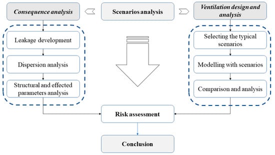
Figure 1.
Procedure for risk assessment of the fuel preparation room.
Scenario analysis: If a hydrogen leak occurs in FPRs, there is a possibility of dispersion and ignition, resulting in various types of fires [28]. However, if the ignition is delayed until the gas disperses and forms a flammable vapor cloud [29], there is a potential for an explosion depending on the concentration of the gas [30]. The occurrence of an explosion can be influenced by multiple scenarios and events [31]. To identify all the potential pathways resulting in an explosion, an ETA was conducted to consider the safety systems typically installed in FPRs.
Consequence analysis involves three main components [32]: leakage development, dispersion analysis, and structural and effected parameter analysis. The model and various leak scenarios are established. During the explosion analysis, a CFD program is used to simulate the explosion and calculate the resultant load on the FPR structure. On the other hand, the structural analysis focuses on evaluating the impact of this load on the boundary wall of the FPR.
Ventilation position and designation scenarios are examined to discuss the influence of ventilation on the dispersion and the harmful effects of hydrogen release [3].
Risk assessment: Risk can be defined as the result of multiplying the likelihood of an accident occurring by its impact [33,34]. Typically, the impact is measured in terms of lives lost, injuries sustained, or financial losses incurred [35]. However, in the present situation, there is no immediate threat to human life since the FPR and its surrounding areas are typically unoccupied. Determining the extent of property damage is a complex task since it is contingent upon the unique circumstances involved, making it difficult to quantify [36,37,38]. Due to these factors, it was determined that an assessment of the likelihood of an explosion occurring should be undertaken to compare it against the acceptable probability levels within the industry. Furthermore, the assessment of the impact can be conducted by examining the potential structural strains that the building may experience in the event of an explosion and by comparing them to the allowable stress thresholds of the material.
The framework of the study, as illustrated in Figure 2, consists of three distinct stages. Initially, the design philosophy of the FPR was examined by considering the functional structure of the hydrogen fuel supply system and the safety requirements outlined by the IMO guidelines and local authorities’ regulations. This analysis facilitated the identification of hydrogen leakage scenarios and the determination of calculation parameters. The next part of this study focused on analyzing the theory of hydrogen leakage and dispersion, including the development of a mathematical model for numerical calculations. The outcomes of previous studies were utilized to validate the computational fluid dynamics (CFD) simulation model, and input parameters were established within this model. In the third stage, the simulation results were utilized to analyze the effects of various factors on hydrogen dispersion and concentration within the FPR. Based on these findings, recommendations for safety design were proposed for ships.
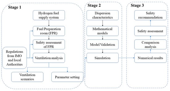
Figure 2.
Research framework.
3. Methodology for Safe Design Ventilation of FPRs
3.1. Hydrogen Leak Event Tree in the Confined Spaces
The diagram depicted in Figure 3 illustrates the event tree for hydrogen leakage within enclosed or confined areas. The occurrences of leakage, detection, ignition sources, and cloud formation are the initial events that lead to the occurrence of hydrogen-related accidents [39,40]. Consequently, comprehending the progression patterns of these events is of utmost importance in managing hydrogen safety, and it represents a central area of focus in FPR research [41].
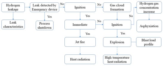
Figure 3.
Leakage event tree of hydrogen in confined space.
In confined spaces, a hydrogen leak event can be analyzed using an event tree to understand the potential consequences and pathways that may result from the leak [42]. The event tree provides a systematic framework for assessing the sequence of the events and their outcomes. The hydrogen leak event tree in confined spaces can be explained in a simplified manner as:
Hydrogen leakage: The event tree begins with the occurrence of a hydrogen leak within the confined space, which could be caused by equipment failure, system malfunction, or human error.
Leak detection: The first branch of the event tree focuses on leak detection mechanisms. If a leak is promptly detected, it leads to the shutdown of the process due to the activation of the emergency shutdown system (ESD). This may involve gas sensors, alarm systems, or visual observation. Upon early detection of the leak, appropriate actions are taken to mitigate the situation. These actions may include activating ventilation systems, isolating the area, and initiating emergency procedures to evacuate personnel [43]. If the early detection and mitigation measures are successful, the event tree proceeds to the “effective mitigation” [44,45]. This indicates that the leak is controlled, and the hydrogen concentration is reduced to safe levels.
No ignition: The “ignition” branch further divides into two possibilities. One possibility is that no ignition source is present within the confined space, leading to the outcome of “no ignition.” In this case, the hydrogen disperses harmlessly, and the incident is resolved without any adverse consequences. The other possibility in the “ignition” branch is the presence of an ignition source. In order to ascertain the likelihoods of instant ignition and delayed ignition, it is crucial to estimate the rate of leakage (in kg/s) for each particular scenario. In the case of a liquid leak, the hydrogen’s initial leak rate can be calculated by conducting the following calculations or procedures [46]:
where is the initial leak rate (kg/s), is the coefficient of the leak, is the area of the leak hole size (m2), is the density of the hydrogen (kg/m3), and is the pressure inside and outside the pipe, respectively (Pa). If an ignition source is present, it leads to the next branch immediately.
Ignition occurs: An ignition event takes place due to the presence of a spark, flame, or other sources of ignition. This can result in a fire or explosion within the confined space, leading to potential damage to the equipment, infrastructure, and, most importantly, the risk of injuries or fatalities to personnel.
Consequences: The “ignition occurs” branch further divides into potential consequences [47,48]. These consequences may include fire suppression efforts, evacuation procedures, medical assistance, and damage control measures to limit the impact of the fire or explosion.
Incident resolution: The final outcome of the event tree is the resolution of the incident [49,50]. This entails extinguishing the fire, securing the area, conducting investigations to determine the root cause, implementing corrective measures, and ensuring that the confined space is safe for re-entry [51,52].
It is crucial to acknowledge that the actual event tree could be more intricate and comprehensive due to the specific factors and mitigation strategies that are pertinent to the particular confined space and hydrogen system under consideration. The event tree analysis assists in understanding the potential outcomes of a hydrogen leak event and aids in developing preventive and responsive measures to enhance safety and minimize risks.
3.2. Leakage Progress of Hydrogen Release
The release of hydrogen is followed by low-flashpoint fuel characteristics and includes four stages [53,54,55]:
Initially, this phase involves the occurrence of a hydrogen leak from the tank, piping, hoses, and so on. During this stage, hydrogen comes into contact with the surrounding air. As hydrogen, in its cooled state, is denser than air, it gathers to form a pool of low-temperature hydrogen [56].
In the second phase, hydrogen that has accumulated as a low-temperature pool, either on the ground or on the surface of the floor, is dispersed extensively [57].
Subsequently, in the third stage, due to the typically higher atmospheric temperature compared to the boiling point of hydrogen [58], the surrounding heat causes the hydrogen to evaporate.
Consequently, a broad vapor cloud consisting of low-temperature gas is generated [59]. Ultimately, the vapor cloud undergoes diffusion through ventilation, spreading, and dispersion in the surrounding area [60,61].
Figure 4 illustrates a schematic diagram depicting the process of hydrogen leakage and diffusion. Each step of the process involves variations in the state of the leaked hydrogen, the quantity of leakage, and the extent of diffusion. Furthermore, considering the time required for hydrogen to leak, absorb heat, evaporate, and diffuse, both the leakage duration and the time taken for CFD analysis are crucial factors when establishing the safety management area for hydrogen leakage.
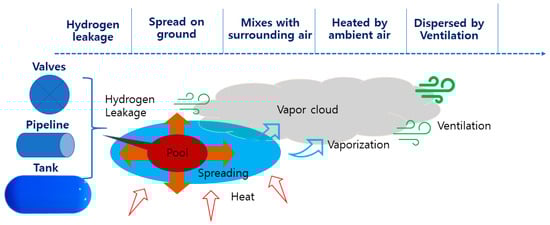
Figure 4.
Hydrogen leakage procedure.
However, in previous studies conducted in relation to the safety assessment of hydrogen leakage in confined spaces, the difference between leakage time and interpretation time is not large. Due to this, it may be difficult to include various changes occurring in the hydrogen leakage process. In this study, when performing an analysis to examine the safety of FPR, the leakage trend and the lower flammable limit range according to the analysis time are analyzed and reflected in the designation of ventilation related to the safety of FPRs.
3.3. Safe Designation of Ventilation for FPRs
When there is a leak of liquid or gaseous fuel from a section of the fuel gas supply system (FGSS), it has the potential to vaporize, disperse, and accumulate within the room [62]. The ventilation system plays a crucial role in effectively eliminating the fuel release and reducing its concentration levels. However, if the ventilation system fails during a leak incident, this important safety mechanism becomes ineffective and unable to fulfill its purpose because the dispersion and explosion can have a detrimental effect on the structural integrity of the FPR in any direction. This damage can potentially result in the further propagation of the accident to adjacent compartments or areas. Due to the significance of damage to adjoining spaces, the ventilation design for the FPR is of utmost importance. A poorly designed ventilation system can contribute to significantly more severe consequences. Consequently, the consequence analysis conducted in this study specifically concentrated on assessing the impact of the ventilation position on the dispersion characteristics of hydrogen.
Figure 5 presents the procedure for the safe designation of FPRs for the hydrogen-fueled ship by employing the deterministic approach.
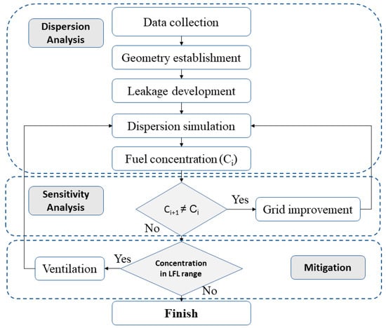
Figure 5.
Safe designation and analysis methodology for ventilation of FPRs.
The safe design process for the ventilation of FPRs in this study is an improved version of the deterministic approach recommended by Dadashzadeh et al. [25]. The procedure for this study is organized into three primary steps, aligning with the intended purpose and scope of the research: (i) dispersion analysis, (ii) sensitivity analysis, (iii) mitigation.
3.4. Dispersion Analysis
During the initial phase, an extensive review is conducted on the regulations and guidelines provided by the classification societies and management authorities. The insights and recommendations obtained from these sources serve as the foundational references for developing and implementing ventilation systems to ensure the safety of FPRs. The field survey of the FPRs of the targeted vessel is carried out to gather and measure the geometry and other affected parameters. All the accident scenarios determined from the scenario analysis were subject to the estimation of the probability of their occurrence and to the evaluation of their consequent impact in the following steps. A field survey is conducted in the FPRs of the targeted vessel to gather and measure various parameters related to their geometry and other relevant factors. Subsequently, all potential accident scenarios identified through scenario analysis undergo an assessment in the subsequent steps. This assessment involves estimating the probability of occurrence for each scenario and evaluating the resulting impact it would have.
3.5. Sensitivity Analysis
The frequency analysis results represent the likelihood of each accident scenario in relation to the initial gas dispersion behavior. The grid size is optimal to form a balance between the output results and computational costs.
3.6. Mitigation
Multiple ventilation scenarios were devised and evaluated, considering factors such as ventilation size, position, and geometry effects. The impact of these factors on the ventilation system was estimated and incorporated into the scenarios. The frequency of occurrence for each accident scenario can be calculated by multiplying the probabilities of each variable under the given conditions.
On the other hand, the outcomes of the consequence analysis were expressed as the safety assessment of the FPRs in each ventilation case.
4. Case Study
4.1. Selected Information
In order to assess the risk associated with FPRs, a 750 DWT powered by hydrogen was selected as the ship for this case study. This ship is a type of fishing ship designed by Hanjin Heavy Industry, Co., Ltd., Busan, Republic of Korea. The FPR is 10.2 m long, 2.65 m high, and 5.3 m wide. The main specifications of the target ship are presented in Table 1.

Table 1.
Selected conditions for bunkering accident.
The arrangement of the FPRs on the target ship is presented in Figure 6.
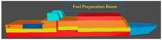
Figure 6.
The arrangement of FPRs on target ship.
Initially, the FPR’s boundary walls were constructed without specific regard for potential leakage dispersion and the ventilation of hydrogen dispersion to minimize the consequences and damage. Instead, it was designed in accordance with the standard approach to ship structural design, which focuses on withstanding machinery and on the availability in comparable situations. Nonetheless, in the process of analyzing the potential outcomes, four scenario groups of improved designs were also examined.
In the event of a gas leak being identified, the ESD system is activated to isolate the engine room that is affected, allowing the other engine rooms to remain operational. Due to this setup, there is no need for double-walled pipes. Furthermore, all the enclosed areas are equipped with mechanical ventilation systems of the exhaust type, ensuring a minimum air exchange rate of 30 times per hour.
4.2. Mathematical Models
For this analysis, a simulation was conducted using a commercial CFD software called FLACS-CFD Ver. 20.2, developed by Gexcon AS (Bergen, Norway). The software combines the Reynolds-averaged Navier–Stokes equations with the k-ε model for turbulence equations. In order to achieve research targets, a two-dimensional (2D) cut plane simulation model was created and visualized using Flowvis. This model was employed to determine the distance of the vapor dispersion in the event of a leakage scenario. The release of flammable gas was assumed to be continuous, and the rate of leakage was calculated using the Bernoulli equation. The simulation focused on two main aspects: hydrogen leakage at the source and the subsequent dispersion in the atmosphere.
The mass flow rate of an ongoing leakage source resulting from a bunkering hose failure can be determined by [63,64]:
where is the flow coefficient of the leakage, is the flow area of the leakage, is the vertical distance from the surface of the hydrogen pool to the center of the leakage hole (in this case, hydrogen leakage is assumed at the bunkering hose; so, is taken to 0).
The transition between the liquid and vapor phases is represented through the utilization of the mixture multiphase flow in the modeling process. When hydrogen leaks, heat conduction occurs between the hydrogen and the ground, causing a drop in temperature at the lower part of the pool. Consequently, the temperature disparity between the hydrogen and the surface of the pool diminishes rapidly, resulting in a reduction in the rate of hydrogen evaporation.
Turbulent kinetic energy k equation [45]:
Turbulent dissipation rate equation [37,44,45]:
Conservation of mass [65]:
Conservation of momentum [65]:
Conservation of energy [65]:
where C1, C2, C3 represent the constant coefficients, represents the kinetic energy turbulent by laminar velocity gradient, represents the wave produced by transition diffusion, represents the kinetic energy turbulent produced by buoyancy, is the velocity, is the density, is the kinetic energy turbulent of dissipation, is the pressure, and t is the time.
In the event of a sudden hydrogen leak occurring at a particular location, there is a drop in pressure, leading to a flashing phenomenon where the leaked hydrogen rapidly transitions from a liquid to a vapor state. This flashing process consumes the heat required for evaporation, causing a decrease in temperature for the remaining liquid inside the pipes. To calculate the proportion of hydrogen that has evaporated in this situation, the following calculation can be employed:
From the F value, the prediction of the form of leakage out of the bunkering hose can be made [63]: (i) F = 0: there is no liquid out; (ii) F = 0.1: there is 50% of the liquid at the time of calculation; (iii) F > 0.2: there is a pool which is liquid in form; (iv): F < 0.2: linear relation between F and liquid.
In the simulation case, where the formation of a liquid pool and flashing only occur shortly after the initial leakage, the vaporization rate can be calculated by:
4.3. Scenarios
The process of hydrogen leakage takes place in the FPR; so, the flow and dispersion process of the gas is greatly affected by the ventilation condition (position of ventilation), the shape of the FPR, and the arrangement of the equipment in the FPR. According to the IGF code [22,66] and other classification regulations [23,67], the flat type of FPR is selected for modeling. The arrangement of ventilation is changed based on the type of FPR, accordingly. The cylinder type of equipment is arranged in the FPR to model the machinery and devices.
The FPR used in this case study had dimensions of 10.2 m × 5.3 m × 2.65 m. According to the IGF Code, it is obligatory for all FPRs to be fitted with a gas detection system. In this case, the assumption was made that the gas detection system would be activated after 10 s of leakage [68,69]. Furthermore, a mechanical ventilation system of the exhaust type was required, with a capacity to provide 30 air changes per hour. This ventilation system serves the purpose of constantly expelling flammable gases from the space. The release rate is assumed to be 0.05 kg/s for 10 s. After 10 s of leakage, the emergency shutdown system is operated and provides a quick and efficient means of shutting down equipment or processes in these emergency situations. The two example types of considered geometry are presented in Figure 7 and Figure 8 below. As presented in the figures, the two forced inlet and outlet ventilation fans are arranged in the FPR with a rectangle shape. The original case of ventilation is arranged in the top side. The scenarios are made on the long side and short side of the FPR to examine the trend of hydrogen dispersion in the FPR and effect of ventilation on the safety of the FPR.
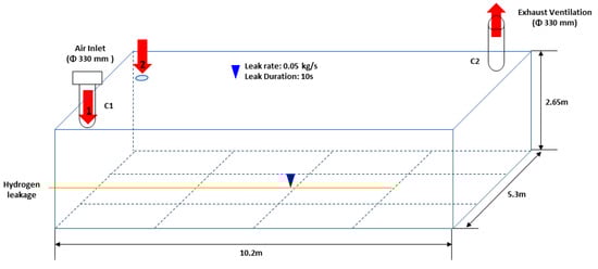
Figure 7.
Top inlet position of FPR.
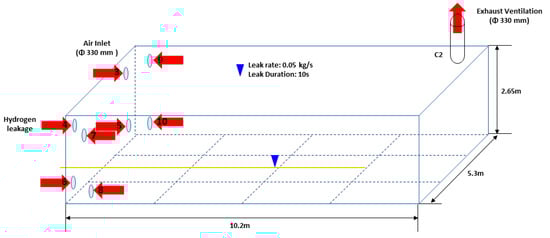
Figure 8.
Size inlet position of FPR.
Dispersion and ventilation scenarios comprise the following ten (10) cases, based on the facility in which a dispersion of hydrogen leakage gas takes place in the FPR. The multiple cases of inlet ventilation are arranged and examined to show the effect of inlet ventilation on the cloud dispersion and the hazard level of the FPR in the case of leakage. The four scenario groups that were made are:
Scenario group 1: Ventilation inlets are arranged in the top side of the FPR.
Scenario group 2: Ventilation inlets are arranged in the back wall of the FPR.
Scenario group 3: Ventilation inlets are arranged in the long side (front) of the FPR.
Scenario group 4: Ventilation inlets are arranged in the long side (back) of the FPR.
The details of the analyzed cases are presented in Table 2 below.
Table 2.
Arrangement of ventilation cases.
A typical outlet position at the top was selected as the standard case; the leak hole area was set as 0.06 m2, the release pressure was 10 bars, and the initial gas temperature was −252 °C. According to Equation (2), the leakage rate of the hydrogen release was 0.05 kg/s. In order to investigate which kind of gas has more influence on the deck, the gas composition was chosen based on buoyancy considerations and gas reactivity. Based on the analysis conducted, two potential harmful outcomes were identified: dispersion and explosion. However, the possibility of asphyxiation was disregarded in this assessment. This choice was determined by assuming that the likelihood of individuals being present in the fuel preparation room (FPR) was low, considering that the FGSS is usually operated remotely and duty engineers are not directly exposed to any potential leakage occurring in the room.
4.4. Simulation Domain and Mesh
The hydrogen leakage experiment mentioned above was chosen as the basis of the physical model, which was carried out by Flacs-CFD geometry. The simulation was performed in the 3D computational domain with dimensions of 14.6 m × 9.7 m × 6.2 m in the X, Y, and Z directions. The core domain was selected to have the dimensions 10.2 m × 5.3 m × 2.65 m. The simulation domain was refined with a total of 36,270 grid cells. The setting up of smallest grid cell had a size of 0.63 m in all the planes. The size of the grid cells was extended in all directions away from the leak position. The hydrogen was assumed to release at a rate of 0.05 kg/s into 0.06 m2 of leak hole area. The leakage position was at (7.6, 3.5, 0.2) for the (x, y, z) axials. The 3D geometrical of computational domain is presented in Figure 9.
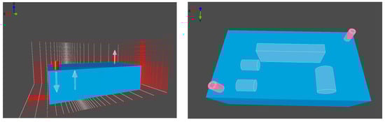
Figure 9.
The 3D geometrical of the computational domain.
In the simulation conducted, it was assumed that the ventilation velocity and temperature remained constant based on the simulation conditions. Both air and hydrogen were treated as incompressible fluids in the simulation. The effects of turbulence in the surrounding atmosphere and hydrogen vapor were predicted using the k-ε model. The heat transfer was calculated using the energy equation.
When it comes to describing turbulent motion, two commonly used models are the standard k-ε model and the realizable k-ε model. However, the realizable k-ε model offers advantages in solving curved wall flows and simulating free flows with jets and mixed flows. Therefore, the realizable k-ε model was selected to model gas diffusion turbulence in this study.
In the leakage region, a class of neutral stability (Pasquill D class) was used in the simulations, and the supposed average wind speed was 3.6 m/s at a height of 4.6 m. The wind direction was set to be north (x direction in this simulation). The wind profile was established at the inlet boundaries, and the stability class is used to calculate the profiles of the turbulent kinetic energy and turbulent dissipation rate. At the ground, a no-slip condition was specified, and the exits used a passive outflow condition.
Monitoring the changing fuel concentration over time in an FPR is an important task to ensure the quality and consistency of the fuel being produced. Placing a monitoring point in the fuel preparation room can be an effective way to record the changing fuel concentration over time (Figure 10). By monitoring the fuel concentration at this location, the valuable data can be gathered, and insights into the fuel quality and its variations can be gained.
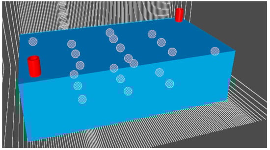
Figure 10.
Arrangement of monitoring points in FPR.
The monitoring points in the FPR serve as sensors to track and record various parameters during the dispersion process, including fuel concentration, fuel velocity, and the arrangement of the vapor cloud. The specifics of each monitoring point are described in Table 3 below.
Table 3.
Arrangement of monitoring points in the FPR.
These monitoring points play a crucial role in tracking and analyzing how these parameters evolve over time within the FPR during the dispersion event. At each monitoring point, these parameters are measured and monitored to observe and analyze the changes that occur over time during the dispersion process within the FPR. By monitoring these parameters, the sensors provide valuable information about the behavior and characteristics of the fuel and vapor cloud throughout the dispersion period in the FPR. These data are used for analysis and safety assessment or to inform decision-making processes related to the management and control of the fuel or vapor in the FPR environment.
5. Results and Discussion
The simulation provided insights into the dispersion characteristics of the hydrogen vapor cloud within the FPR. It revealed the spatial distribution and movement of the cloud, allowing for a better understanding of how it spreads and interacts with the surrounding environment. Based on the simulation findings, discussions can revolve around potential optimization opportunities for the FPR design, ventilation system layout, or safety protocols. The data obtained from this study can be utilized to identify areas that require improvement, to enhance safety measures, and to mitigate the risks associated with the dispersion of hydrogen vapor clouds. It may be beneficial to perform a sensitivity analysis to explore the impact of various factors on hydrogen dispersion. This could involve assessing the effects of ventilation configurations or FPR geometries on the diffusion characteristics of the hydrogen vapor cloud.
The hydrogen velocity and concentration inside the FPR were observed for each scenario. These parameters play a crucial role in the analysis of hydrogen release and dispersion since they directly impact the risk of ignition. The hydrogen concentration profile within the compartment indicates areas that carry the risk of fire, which falls within the hydrogen concentration range of 4–75%.
5.1. Ventilation in Top Side Plan
Based on the information presented in Figure 11, elevated concentrations were observed in the upper regions of the compartment, specifically near the ceiling. This concentration pattern is attributed to the accumulation of hydrogen gas, which is lighter than air and exhibits a significant buoyancy effect. The findings indicate that the entire compartment is exposed to the possibility of catching fire. However, the front section of the compartment and the regions beneath the ceiling are particularly susceptible to ignition. Specifically, the hydrogen supply system starter situated at the front of the FPR and the light bulbs or electric devices mounted under the ceiling could potentially act as sources of ignition in these areas. Due to its buoyancy and because it weighs 14 times less than air, the gas flow moves upwards and from the rear to the front of the compartment after being released as it becomes trapped beneath the ceiling.
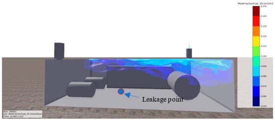
Figure 11.
The 3D plant of hydrogen leakage dispersion.
The 3D simulation results and the 2D cut plan of hydrogen dispersion after 10 s (the time that the ESD is in operation) are presented in Figure 12. The 3D simulation results likely illustrate the spatial distribution of the hydrogen vapor cloud within the FPR, providing a comprehensive view of its dispersion pattern in three dimensions. Additionally, the 2D cut plan, which represents a section or slice of the FPR, allows a more detailed visualization of the dispersion characteristics of the hydrogen vapor cloud at the specified time. This cut plan provides information on the concentration levels and the spatial arrangement of the hydrogen cloud within the FPR.
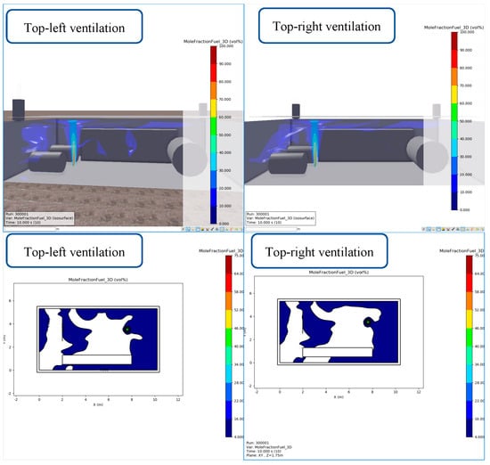
Figure 12.
Ventilation on top side of FPR (after 10 s of leakage).
Figure 12 illustrates the dispersion concentration of hydrogen release in two different cases of inlet ventilation. In both cases, the ventilation is located in the two corners of the top plate of the FPR. The figure specifically depicts the dispersion concentration at 10 s after the release of hydrogen. The analysis of the results shows that in both cases, the high concentration of the dispersed hydrogen is observed in the confined space formed by the equipment and the wall. This indicates that there is a localized accumulation of hydrogen in that particular area, which could pose a potential risk. Furthermore, the figure highlights the differences in the dispersion arrangement between the two ventilation cases. Although these differences exist, they are not significantly large. This implies that the choice of ventilation location has some influence on the dispersion pattern, but the overall impact on the concentration distribution within the FPR is relatively minor. By considering these findings, it is important to acknowledge the presence of high hydrogen concentrations in confined spaces within the FPR, regardless of the specific ventilation arrangement. This information can help in implementing appropriate safety measures, such as improved ventilation strategies or modifications to the FPR design to mitigate the risks associated with hydrogen dispersion.
After 138 s of leakage, the dispersion cloud was almost discharged out of the FPR under the effect of inlet and outlet ventilation. However, for the top-right inlet ventilation, the small cloud accumulated on the long side of the FPR, as shown in Figure 13. Thus, inlet ventilation on the same side as the outlet ventilation resulted in a longer dispersion time and concentration in the FPR.
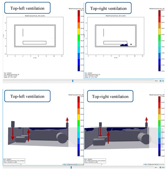
Figure 13.
Dispersion of hydrogen release after 136 s of leakage.
If the inlet ventilation and outlet ventilation in the fuel preparation room are located on the same side, it can indeed result in longer dispersion times and higher concentrations of hydrogen vapor within the room. This configuration can hinder the effective removal of the gas and increase the risk of accumulation. When the ventilation inlets and outlets are located on the same side, the airflow within the room becomes limited and less efficient. The fresh air brought in by the inlet ventilation may not effectively mix with the hydrogen vapor, leading to slower dispersion. At the same time, the outlet ventilation may struggle to exhaust the hydrogen-laden air adequately. As a result, the concentration of hydrogen can increase in the fuel preparation room, particularly in areas farther away from the ventilation openings. The longer dispersion time means that it will take more time for the hydrogen to disperse and dilute to safe levels [70]. To address this issue, it is generally recommended to design the ventilation system in a way that promotes good airflow and effective dispersion of hydrogen vapor. This often involves having the inlet and outlet ventilation located on opposite sides of the room, which facilitates cross-ventilation and a more efficient exchange of air. By optimizing the ventilation system’s design and positioning, the dispersion time of hydrogen vapor can be reduced, and the concentration levels can be kept within safe limits.
In addition to the ventilation position, the arrangement and size of the equipment in the FPR also affect the dispersion characteristics of the hydrogen release. In the FPR, the arrangement and size of the equipment can indeed influence the dispersion characteristics of the hydrogen release. Hydrogen is a highly flammable gas, and its dispersion behavior is important to consider for safety reasons. When equipment is placed in a fuel preparation room, it can create spaces or corners where hydrogen vapor tends to accumulate. This can happen when there are obstructions or barriers that impede the free flow of the gas. Hydrogen, being lighter than air, tends to rise and accumulate in areas where it cannot easily disperse. The accumulation of hydrogen vapor in confined spaces or corners can be hazardous because it increases the likelihood of a flammable mixture forming. If there is an ignition source present, such as a spark or flame, it can lead to a fire or an explosion. To mitigate this risk, it is important to carefully plan the layout and size of the equipment in the fuel preparation room. This involves considering factors such as the spacing between equipment, the positioning of ventilation systems, and the overall design of the room to ensure adequate dispersion of the hydrogen vapor.
Additionally, other safety measures can be implemented, such as installing gas detection systems that can monitor hydrogen levels in the room. These systems can provide early warning signs if there is a potential buildup of hydrogen vapor. Overall, ensuring proper ventilation and thoughtful equipment arrangement and considering the dispersion characteristics of hydrogen release are crucial for maintaining a safe environment in a fuel preparation room.
5.2. Ventilation in Width Side (Back Wall)
As in the initial simulation, elevated fuel concentrations were noted in the vicinity of the release point and beneath the ceiling. However, there was a slight decline in fuel concentration at the lower sections of the compartment near the opening.
Based on the findings depicted in Figure 14 and Figure 15, which illustrate the dispersion results in both 2D and 3D after 10 s, the hydrogen flow initially moves upwards following the release due to the pronounced buoyancy effects. Subsequently, the flow transitions towards the front of the compartment as a result of the accumulation of hydrogen underneath the ceiling. At the exhaust location, a pathway is created for the gas to be released into the surrounding atmosphere. The outward flow of the hydrogen creates a negative pressure on the inner side of the exhaust opening. Consequently, the accumulated hydrogen under the ceiling, influenced by this negative pressure, moves downwards and escapes through the exhaust, leading to a significant decrease in hydrogen concentration within the FPR.
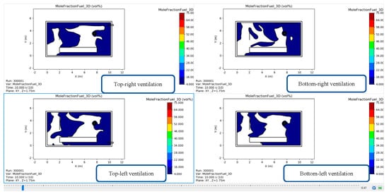
Figure 14.
Dispersion characteristics under different inlet ventilation positions in back wall.
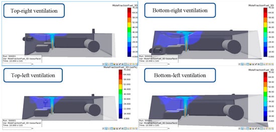
Figure 15.
Three-dimensional view of hydrogen dispersion under 10 s with back wall ventilation.
As presented in Figure 16, after 178 s of hydrogen leakage, the ventilation in the top position ventilated more quickly than the ventilation in the bottom position. The ventilation in the left side (opposite the side with the outlet ventilation) dispersed more quickly than that in the right side (same side as the outlet ventilation).
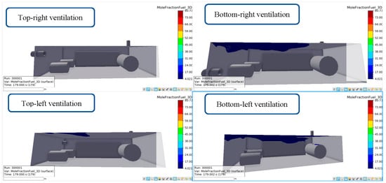
Figure 16.
Dispersion characteristics of hydrogen release after 178 s of leakage.
The ventilation openings located at the top of the room generally facilitated quicker ventilation compared to those at the bottom. This is because hydrogen is lighter than air and tends to rise. When the ventilation was positioned at the top, it allowed the direct removal of the hydrogen vapor, enabling faster dispersion and reducing the risk of accumulation.
On the other hand, ventilation openings on the bottom may not be as effective in removing hydrogen vapor since the gas tends to rise and accumulate near the ceiling. However, having ventilation openings at the bottom can still be beneficial in promoting general air circulation and preventing stagnant pockets of hydrogen. Regarding the side of the room where the ventilation is placed, the ventilation on the left side (opposite side to the outlet ventilation) is indeed likely to result in quicker dispersion compared to the right side (same side as the outlet ventilation). This is because a cross-ventilation pattern is generally more effective at promoting air circulation and dispersion. When ventilation openings are positioned on opposite sides, they allow air to flow across the room, carrying the hydrogen vapor with it and facilitating faster dispersion. On the other hand, having both ventilation openings on the same side, where the outlet ventilation is located, can hinder the cross-ventilation and result in slower dispersion.
It is important to consider these factors when designing the ventilation system for a fuel preparation room to ensure effective dispersion and minimize the risk of hydrogen accumulation. By strategically placing ventilation openings at the top and on the opposite side of the outlet ventilation, quicker and more efficient ventilation can be promoted, improving the safety of the environment.
5.3. Ventilation in Long Side (Top and Bottom Places of Front and Back Wall of FPR)
The fuel mole concentration arrangement after 10 s of hydrogen release is presented in Figure 17 and Figure 18. Following the release, the flammable gas exhibits an upward movement owing to the buoyancy effect at the rear of the area. However, the air flow, facilitated by the fan, counteracts this movement by pushing the gas downwards, compelling it to escape through the rear exhaust. As a result, the forced air flow becomes dominant, rendering the rear vent as effective as the front opening in terms of gas dispersion. The remaining flammable gas, accumulated beneath the ceiling, is pushed towards the front section of the FPR due to the forced airflow. Subsequently, it flows downwards near the front wall due to the combination of forced ventilation and the negative pressure generated at the inner side of the front opening.
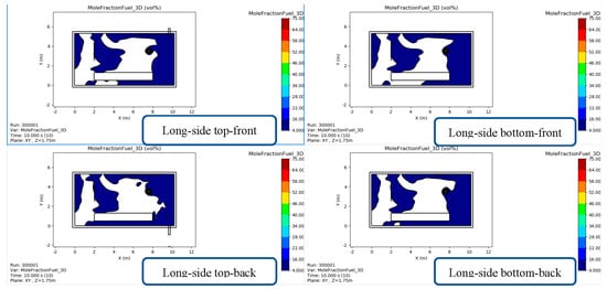
Figure 17.
Two-dimensional cut plan of simulation results of dispersion characteristics of hydrogen release after 10 s with ventilation inlet in side parts.
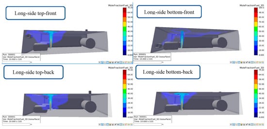
Figure 18.
Three-dimensional simulation results of dispersion characteristics of hydrogen release after 10 s with ventilation inlet in side parts.
As presented in Figure 19, after 155 s of hydrogen release, the inlet ventilation in the top sides was more efficient than the inlet ventilation in the bottom position. The inlet ventilation on the same side (same plate) as the outlet ventilation was more effective than the inlet ventilation on the side opposite to the outlet ventilation.
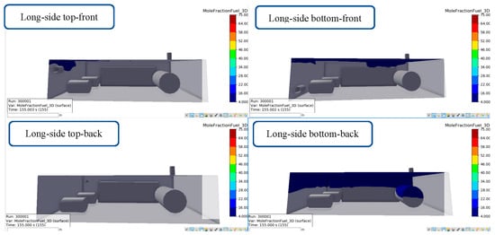
Figure 19.
Three-dimensional simulation results of dispersion characteristics of hydrogen release after 155 s with ventilation inlet in side parts.
Inlet ventilation located at the top of the room is generally more efficient than inlet ventilation at the bottom. This is because hydrogen is lighter than air and tends to rise. By placing the inlet ventilation openings at the top, it allows the direct introduction of fresh air and the efficient removal of hydrogen vapor, facilitating quicker dispersion.
Additionally, having inlet ventilation on the same side (same plate) as the outlet ventilation can indeed be more effective than having the inlet ventilation on the side of the FPR opposite to that of the outlet ventilation. When the inlet and outlet ventilation are on the same side, it creates a flow pattern that promotes more direct airflow across the room. This can enhance the exchange of air, leading to better dispersion of hydrogen vapor and more efficient ventilation. On the other hand, if the inlet and outlet ventilation are on opposite sides of the room, the airflow may not be as direct or effective in carrying the hydrogen vapor across the room. This can result in slower dispersion and potentially higher concentrations of hydrogen in certain areas. Therefore, placing the inlet ventilation at the top and on the same side as the outlet ventilation can improve the efficiency of the ventilation system and contribute to better dispersion characteristics in a fuel preparation room. It is important to consider these factors and consult with experts or adhere to the relevant safety guidelines when designing the ventilation system for a fuel preparation room to ensure proper dispersion of hydrogen vapor and maintain a safe environment.
5.4. The Change of Scalar Time through Four Typical Case Scenarios
Based on the simulations and analysis of the four scenario groups mentioned above, the four optimal inlet ventilating cases are selected and compared in Figure 20. As in above analysis, the four typical cases of each scenario group are selected, including: case numbers 2 (top-left ventilation), 3 (back wall top left), 7 (long side top front) and 9 (long side top back).
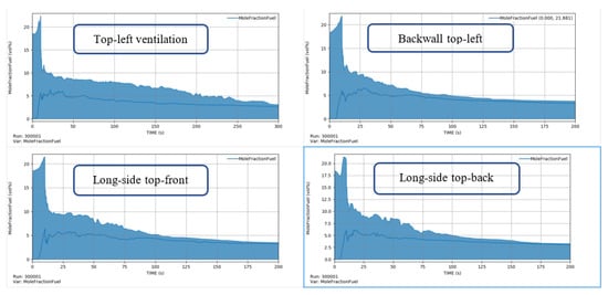
Figure 20.
Scalar time for fuel mole concentration in the monitoring point according to time.
Figure 20 illustrates the temporal changes in fuel mole concentration for each scenario. The y-axis in each scenario represents the relative fuel mole concentration, referenced to the concentration designated as 0 on the y-axis at the initial time of dispersion. The concentration diagram is made from the information of the 31 sensors (monitoring points) mentioned in Table 3. Four quick and optimal ventilation cases are compared and presented in Figure 20. In the comparison of the four highest concentration cases, it is important to note that the flammable limit of hydrogen falls within the range of 4–75%. Therefore, any dispersion that falls outside of this range can generally be considered as safely dispersed. Thus, as presented in Figure 20, the top-left and back wall top-left ventilation are presented to a higher concentration than the others.
When evaluating the dispersion characteristics, it is crucial to analyze the concentration levels of hydrogen vapor in the FPR. Cases with concentrations below 4% or above 75% are typically considered to have lower risks of ignition or explosion. By comparing the concentration levels of hydrogen vapor in the four highest concentration cases, it becomes possible to identify the scenarios that pose the highest potential risks. Understanding these concentrations aids in assessing the effectiveness of the ventilation system and in determining whether additional measures are necessary to ensure safe dispersion.
However, it is important to emphasize that even concentrations falling within the flammable range of 4–75% should be treated with caution. Proper ventilation, equipment arrangement, and adherence to safety guidelines remain critical in mitigating the potential hazards associated with hydrogen release and dispersion. By considering the concentration levels and implementing appropriate safety measures, it is possible to minimize the risks and create a safer environment in the fuel preparation room.
6. Conclusions
In conclusion, the dispersion characteristics of hydrogen release in the FPR are influenced by several factors, including the arrangement and size of equipment and the positioning of ventilation openings. Hydrogen vapor tends to accumulate in corners and spaces formed by the equipment, posing potential risks of flammable mixtures. Effective ventilation is crucial for promoting the safe dispersal of hydrogen vapor and minimizing the concentration levels within the room. Our discussion highlighted the importance of considering the position of ventilation openings, with top inlet ventilation proving more efficient in facilitating quick dispersion. Additionally, locating the inlet ventilation on the same side as the outlet ventilation was found to hinder dispersion, while cross-ventilation, achieved by placing inlets and outlets on opposite sides, enhanced airflow and dispersion. These insights emphasize the significance of careful design and adherence to safety guidelines in ensuring proper ventilation and mitigating the potential hazards associated with hydrogen release in FPRs:
- ①
- The arrangement and size of the equipment in the FPR can impact the dispersion of hydrogen vapor. The hydrogen vapor tends to accumulate in corners and spaces created by the equipment.
- ②
- The efficiency of ventilation is influenced by the position of the inlet and outlet openings. Top inlet ventilation is generally more efficient in promoting the quick dispersion of hydrogen vapor.
- ③
- Inlet ventilation on the same side as the outlet ventilation can hinder dispersion and increase the risk of accumulation. Cross-ventilation, achieved by placing inlet ventilation on the opposite side to that of the outlet ventilation, enhances airflow and dispersion.
- ④
- Consideration of airflow patterns, hydrogen behavior, and safety guidelines is crucial in designing the ventilation system. Thus, the proper ventilation design, including top inlet ventilation and outlet ventilation on the opposite side, helps maintain a safe FPR by facilitating efficient dispersion of hydrogen vapor.
Author Contributions
Formal analysis, B.R.R. and P.A.D.; investigation, B.R.R., J.-B.K. and J.W.S.; methodology, B.R.R. and S.-Y.C.; supervision, H.K. and J.J.; writing—original draft, P.A.D.; writing—review and editing, B.R.R., P.A.D., H.K. and J.J. All authors have read and agreed to the published version of the manuscript.
Funding
This research was supported by the Korea Institute of Marine Science & Technology Promotion (KIMST) funded by the Ministry of Oceans and Fisheries, Republic of Korea (20180048, 20200520 and 20200456).
Institutional Review Board Statement
Not applicable.
Informed Consent Statement
Not applicable.
Data Availability Statement
Data are available upon request.
Conflicts of Interest
The authors declare no conflict of interest.
Abbreviations
| FPR | Fuel Preparation Room |
| DWT | Deadweight (ton) |
| GHGs | Greenhouse Gases |
| IMO | The International Maritime Organization |
| MARPOL | The International Convention for the Prevention of Pollution from Ships |
| MSC | Maritime Safety Committee |
| IGF Code | The Code addresses all areas that need special consideration for the usage of the gas or low-flashpoint liquids as fuel |
| LFL | Lower Flammable Limit |
| FGSS | Fuel Gas Supply system |
| LNG | Liquefied Natural Gas |
| CFD | Computational Fluid Dynamics |
| FSA | Formal Safety Assessment |
| ETA | Even Tree Analysis |
| L.O.A | Length Overall |
| Flow coefficient of the leakage | |
| The flow area of the leakage (m2) | |
| The vertical distance of surface of hydrogen pool to the center of leakage hole |
References
- Zis, T.P.V.; Psaraftis, H.N.; Tillig, F.; Ringsberg, J.W. Decarbonizing maritime transport: A Ro-Pax case study. Res. Transp. Bus. Manag. 2020, 37, 100565. [Google Scholar] [CrossRef]
- Duong, P.A.; Ryu, B.; Jung, J.; Kang, H. Thermal Evaluation of a Novel Integrated System Based on Solid Oxide Fuel Cells and Combined Heat and Power Production Using Ammonia as Fuel. Appl. Sci. 2022, 12, 6287. [Google Scholar] [CrossRef]
- Goswami, R.; Sun, B. Study on vapour dispersion and explosion from compressed hydrogen spill: Risk assessment on a hydrogen plant. Int. J. Hydrogen Energy 2022, 47, 41195–41207. [Google Scholar] [CrossRef]
- Duong, P.A.; Ryu, B.; Jung, J.; Kang, H. Design, Modelling, and Thermodynamic Analysis of a Novel Marine Power System Based on Methanol Solid Oxide Fuel Cells, Integrated Proton Exchange Membrane Fuel Cells, and Combined Heat and Power Production. Sustainability 2022, 14, 12496. [Google Scholar] [CrossRef]
- International Maritime Organization. Initial IMO Strategy on reduction of GHG emission from ships. Resolution MEPC.304(72) (adopted on 13 April 2018).
- MARPOL. Annex IV of MARPOL 73/78 Regulations for the Prevention of Pollution by Sewage from Ships. Marpol 1997, 78. Available online: https://static.pmg.org.za/140729annexiv.pdf (accessed on 3 May 2023).
- Duong, P.A.; Ryu, B.; Kim, C.; Lee, J.; Kang, H. Energy and Exergy Analysis of an Ammonia Fuel Cell Integrated System for Marine Vessels. Energies 2022, 15, 3331. [Google Scholar] [CrossRef]
- Ryu, B.; Duong, P.A.; Kang, H. Comparative analysis of the thermodynamic performances of solid oxide fuel cell–gas turbine integrated systems for marine vessels using ammonia and hydrogen as fuels. Int. J. Nav. Archit. Ocean Eng. 2023, 15, 100524. [Google Scholar] [CrossRef]
- Heo, J.W.; Choi, Y.H.; Kim, S.H.; Lee, S.H.; Choi, H.Y.; Yu, D.I.; Lee, Y.W. Predicting heat transfer performance in a complex heat exchanger for LNG FGSS development. J. Adv. Mar. Eng. Technol. 2023, 47, 52–58. [Google Scholar] [CrossRef]
- Jung, J.; Duong, P.A.; Ryu, B.R.; Kang, H. Using Tesla turbine for waste heat recovery: Currents status and future directions. J. Adv. Mar. Eng. Technol. 2023, 47, 105–119. [Google Scholar] [CrossRef]
- Penner, S.S. Steps toward the hydrogen economy. Energy 2006, 31, 33–43. [Google Scholar] [CrossRef]
- Kim, B.; Hwang, K. Il Numerical Analysis of the Effects of Ship Motion on Hydrogen Release and Dispersion in an Enclosed Area. Appl. Sci. 2022, 12, 1259. [Google Scholar] [CrossRef]
- Nguyen, Q.H.; Duong, P.A.; Ryu, B.R.; Kang, H. A study on performances of SOFC integrated system for hydrogen-fueled vessel. J. Adv. Mar. Eng. Technol. 2023, 47, 120–130. [Google Scholar] [CrossRef]
- Rigas, F.; Sklavounos, S. Evaluation of hazards associated with hydrogen storage facilities. Int. J. Hydrogen Energy 2005, 30, 1501–1510. [Google Scholar] [CrossRef]
- Lee, H.; Ryu, B.; Anh, D.P.; Roh, G.; Lee, S.; Kang, H. Thermodynamic analysis and assessment of novel ORC- DEC integrated PEMFC system for liquid hydrogen fueled ship application. Int. J. Hydrogen Energy 2023, 48, 3135–3153. [Google Scholar] [CrossRef]
- Kim, E.; Park, J.; Cho, J.H.; Moon, I. Simulation of hydrogen leak and explosion for the safety design of hydrogen fueling station in Korea. Int. J. Hydrogen Energy 2013, 38, 1737–1743. [Google Scholar] [CrossRef]
- Dincer, I. Technical, environmental and exergetic aspects of hydrogen energy systems. Int. J. Hydrogen Energy 2002, 27, 265–285. [Google Scholar] [CrossRef]
- Najjar, Y.S.H. Hydrogen safety: The road toward green technology. Int. J. Hydrogen Energy 2013, 38, 10716–10728. [Google Scholar] [CrossRef]
- Kikukawa, S.; Mitsuhashi, H.; Miyake, A. Risk assessment for liquid hydrogen fueling stations. Int. J. Hydrogen Energy 2009, 34, 1135–1141. [Google Scholar] [CrossRef]
- Lee, B.J.; Jeung, I.S. Numerical study of spontaneous ignition of pressurized hydrogen released by the failure of a rupture disk into a tube. Int. J. Hydrogen Energy 2009, 34, 8763–8769. [Google Scholar] [CrossRef]
- Zheng, J.; Bie, H.; Xu, P.; Liu, P.; Zhao, Y.; Chen, H.; Liu, X.; Zhao, L. Numerical simulation of high-pressure hydrogen jet flames during bonfire test. Int. J. Hydrogen Energy 2012, 37, 783–790. [Google Scholar] [CrossRef]
- IMO. The International Code of Safety for Ships Using Gases or Other Low-Flashpoint Fuels (Igf Code). Imo 2016, 391, 121. [Google Scholar]
- Korean Register. Rules and Guidances for the Classification of Ships Using Low-flashpoint Fuels Ships Using Low-flashpoint Fuels Ships Using Low-flashpoint Fuels. 2019. Available online: https://www.krs.co.kr/KRRules/KRRules2022/data/DATA_OTHER/ENGLISH/rb14e000.pdf (accessed on 3 May 2023).
- Jeong, B.; Lee, B.S.; Zhou, P. Quantitative risk assessment of fuel preparation room having high-pressure fuel gas supply system for LNG fuelled ship. Ocean Eng. 2017, 137, 450–468. [Google Scholar] [CrossRef]
- Dadashzadeh, M.; Ahmad, A.; Khan, F. Dispersion modelling and analysis of hydrogen fuel gas released in an enclosed area: A CFD-based approach. Fuel 2016, 184, 192–201. [Google Scholar] [CrossRef]
- Sehefer, R.W.; Houf, W.G.; Williams, T.C. Investigation of small-scale unintended releases of hydrogen: Momentum-dominated regime. Int. J. Hydrogen Energy 2008, 33, 6373–6384. [Google Scholar] [CrossRef]
- IMO. MSC/Circ.1023. Guidelines for FSA. Imo 2002. Available online: https://wwwcdn.imo.org/localresources/en/OurWork/HumanElement/Documents/1023-MEPC392.pdf (accessed on 3 May 2023).
- Zhang, W.; Zhao, G. Leakage and diffusion characteristics of underground hydrogen pipeline. Petroleum 2023, in press. [Google Scholar] [CrossRef]
- Wang, X.; Gao, W. Hydrogen leakage risk assessment for hydrogen refueling stations. Int. J. Hydrogen Energy 2023, in press. [Google Scholar] [CrossRef]
- ISO 1649-2009; Technical Specification ISO/TS Quality Management Systems—Guidelines for the Application of ISO iTeh Standard Preview iTeh Standard Preview. ISO: Geneva, Switzerland, 2015; Volume 2016.
- Wang, T.; Huang, T.; Hu, S.; Li, Y.; Yang, F.; Ouyang, M. Simulation and risk assessment of hydrogen leakage in hydrogen production container. Int. J. Hydrogen Energy 2023, 48, 20096–20111. [Google Scholar] [CrossRef]
- Wang, X.; Zhang, C.; Gao, W. Risk assessment of hydrogen leakage in diesel hydrogenation process. Int. J. Hydrogen Energy 2022, 47, 6955–6964. [Google Scholar] [CrossRef]
- Brzezińska, D. Hydrogen dispersion phenomenon in nominally closed spaces. Int. J. Hydrogen Energy 2021, 46, 28358–28365. [Google Scholar] [CrossRef]
- Xin, J.; Duan, Q.; Jin, K.; Sun, J. A reduced-scale experimental study of dispersion characteristics of hydrogen leakage in an underground parking garage. Int. J. Hydrogen Energy 2023, 48, 16936–16948. [Google Scholar] [CrossRef]
- Li, Y.; Xiao, J.; Zhang, H.; Breitung, W.; Travis, J.; Kuznetsov, M.; Jordan, T. Numerical analysis of hydrogen release, dispersion and combustion in a tunnel with fuel cell vehicles using all-speed CFD code GASFLOW-MPI. Int. J. Hydrogen Energy 2021, 46, 12474–12486. [Google Scholar] [CrossRef]
- Gong, L.; Yang, S.; Han, Y.; Jin, K.; Lu, L.; Gao, Y.; Zhang, Y. Experimental investigation on the dispersion characteristics and concentration distribution of unignited low-temperature hydrogen release. Process Saf. Environ. Prot. 2022, 160, 676–682. [Google Scholar] [CrossRef]
- Wang, Q.; Zhai, C.; Gong, J.; Wang, Z.; Jiang, J.; Zhou, Y. Analytical and numerical predictions of hydrogen gas flow induced by wall and corner leakages in confined space. Int. J. Hydrogen Energy 2020, 45, 6848–6862. [Google Scholar] [CrossRef]
- Shibani; Salehi, F.; Baalisampang, T.; Abbassi, R. Numerical modeling towards the safety assessment of multiple hydrogen fires in confined areas. Process Saf. Environ. Prot. 2022, 160, 594–609. [Google Scholar] [CrossRef]
- Brady, K.; Sung, C.J.; T’Ien, J. Dispersion and catalytic ignition of hydrogen leaks within enclosed spaces. Int. J. Hydrogen Energy 2012, 37, 10405–10415. [Google Scholar] [CrossRef]
- De Stefano, M.; Rocourt, X.; Sochet, I.; Daudey, N. Hydrogen dispersion in a closed environment. Int. J. Hydrogen Energy 2019, 44, 9031–9040. [Google Scholar] [CrossRef]
- Giannissi, S.G.; Shentsov, V.; Melideo, D.; Cariteau, B.; Baraldi, D.; Venetsanos, A.G.; Molkov, V. CFD benchmark on hydrogen release and dispersion in confined, naturally ventilated space with one vent. Int. J. Hydrogen Energy 2015, 40, 2415–2429. [Google Scholar] [CrossRef]
- Hajji, Y.; Bouteraa, M.; Bournot, P.; Bououdina, M. Assessment of an accidental hydrogen leak from a vehicle tank in a confined space. Int. J. Hydrogen Energy 2022, 47, 28710–28720. [Google Scholar] [CrossRef]
- Tang, X.; Pu, L.; Shao, X.; Lei, G.; Li, Y.; Wang, X. Dispersion behavior and safety study of liquid hydrogen leakage under different application situations. Int. J. Hydrogen Energy 2020, 45, 31278–31288. [Google Scholar] [CrossRef]
- Wang, Q.; Zhai, C.; Gong, J.; Jiang, J.; Wang, Z.; Zhou, Y. Estimating leaked hydrogen gas flow in confined space through coupling zone model and point source buoyancy plume theory. Int. J. Hydrogen Energy 2019, 44, 15644–15656. [Google Scholar] [CrossRef]
- Wang, K.; Zhang, X.; Miao, Y.; He, B.; Wang, C. Dispersion and behavior of hydrogen for the safety design of hydrogen production plant attached with nuclear power plant. Int. J. Hydrogen Energy 2020, 45, 20250–20255. [Google Scholar] [CrossRef]
- Spouge, J. Leak frequencies from the hydrocarbon release database. Inst. Chem. Eng. Symp. Ser. 2006, 151, 732–747. [Google Scholar]
- Zhang, T.; Jiang, Y.; Wang, S.; Pan, X.; Hua, M.; Wang, Z.; Wang, Q.; Li, Y.; Jiang, J. Numerical study on the flow characteristics of pressurized hydrogen leaking into the confined space through different shaped orifices. Int. J. Hydrogen Energy 2022, 47, 35527–35539. [Google Scholar] [CrossRef]
- Li, Y.; Yang, J.; Wu, X.; Liu, Y.; Zhou, P.; Yuhao, Y.; Han, X. Research on the field strength characteristics and the flammable area of refrigerants leakage into a confined space. Int. J. Refrig. 2023, in press. [Google Scholar] [CrossRef]
- Sun, R.; Pu, L.; Yu, H.; Dai, M.; Li, Y. Modeling the diffusion of flammable hydrogen cloud under different liquid hydrogen leakage conditions in a hydrogen refueling station. Int. J. Hydrogen Energy 2022, 47, 25849–25863. [Google Scholar] [CrossRef]
- Gao, Q.; Wang, L.; Peng, W.; Zhang, P.; Chen, S. Safety analysis of leakage in a nuclear hydrogen production system. Int. J. Hydrogen Energy 2022, 47, 4916–4931. [Google Scholar] [CrossRef]
- Zhu, J.; Pan, J.; Zhang, Y.; Li, Y.; Li, H.; Feng, H.; Chen, D.; Kou, Y.; Yang, R. Leakage and diffusion behavior of a buried pipeline of hydrogen-blended natural gas. Int. J. Hydrogen Energy 2022, 48, 11592–11610. [Google Scholar] [CrossRef]
- Wang, T.; Yang, F.; Hu, Q.; Hu, S.; Li, Y.; Ouyang, M. Experimental and simulation research on hydrogen leakage of double ferrule joints. Process Saf. Environ. Prot. 2022, 160, 839–846. [Google Scholar] [CrossRef]
- Li, J.; Xie, W.; Li, H.; Qian, X.; Shi, J.; Xie, Z.; Wang, Q.; Zhang, X.; Chen, G. Real-time hydrogen release and dispersion modelling of hydrogen refuelling station by using deep learning probability approach. Int. J. Hydrogen Energy 2023, in press. [Google Scholar] [CrossRef]
- Bouet, R.; Duplantier, S.; Salvi, O. Ammonia large scale atmospheric dispersion experiments in industrial configurations. J. Loss Prev. Process Ind. 2005, 18, 512–519. [Google Scholar] [CrossRef]
- Tan, W.; Lv, D.; Guo, X.; Du, H.; Liu, L.; Wang, Y. Accident consequence calculation of ammonia dispersion in factory area. J. Loss Prev. Process Ind. 2020, 67, 104271. [Google Scholar] [CrossRef]
- Qian, J.Y.; Li, X.J.; Gao, Z.X.; Jin, Z.J. A numerical study of unintended hydrogen release in a hydrogen refueling station. Int. J. Hydrogen Energy 2020, 45, 20142–20152. [Google Scholar] [CrossRef]
- Shu, Z.; Liang, W.; Zheng, X.; Lei, G.; Cao, P.; Dai, W.; Qian, H. Dispersion characteristics of hydrogen leakage: Comparing the prediction model with the experiment. Energy 2021, 236, 121420. [Google Scholar] [CrossRef]
- Shu, Z.; Lei, G.; Liang, W.; Dai, W.; Lu, F.; Zheng, X.; Qian, H. Experimental investigation of hydrogen dispersion characteristics with liquid helium spills in moist air. Process Saf. Environ. Prot. 2022, 162, 923–931. [Google Scholar] [CrossRef]
- Gitushi, K.M.; Blaylock, M.L.; Klebanoff, L.E. Hydrogen gas dispersion studies for hydrogen fuel cell vessels II: Fuel cell room releases and the influence of ventilation. Int. J. Hydrogen Energy 2022, 47, 21492–21505. [Google Scholar] [CrossRef]
- Liang, Y.; Pan, X.; Zhang, C.; Xie, B.; Liu, S. The simulation and analysis of leakage and explosion at a renewable hydrogen refuelling station. Int. J. Hydrogen Energy 2019, 44, 22608–22619. [Google Scholar] [CrossRef]
- Lacome, J.M.; Jamois, D.; Perrette, L.; Proust, C.H. Large-scale hydrogen release in an isothermal confined area. Int. J. Hydrogen Energy 2011, 36, 2302–2312. [Google Scholar] [CrossRef]
- Mo, F.; Liu, B.; Wang, H.; She, X.; Teng, L.; Kang, X. Study on hydrogen dispersion in confined space with complex air supply and exhaust system. Int. J. Hydrogen Energy 2022, 47, 29131–29147. [Google Scholar] [CrossRef]
- Zhu, D.Z. Example of simulating analysis on LNG leakage and dispersion. Procedia Eng. 2014, 71, 220–229. [Google Scholar] [CrossRef]
- Zhu, G.; Guo, X.; Yi, Y.; Tan, W.; Ji, C. Experiment and simulation research of evolution process for LNG leakage and diffusion. J. Loss Prev. Process Ind. 2020, 64, 104041. [Google Scholar] [CrossRef]
- Kim, C.; Choi, B.C. Dispersion analysis of the unignited flare gas in an LNG-FPSO vessel. J. Korean Soc. Mar. Eng. 2017, 41, 753–759. [Google Scholar] [CrossRef]
- MSC.370(93). Amendments to the International Code for the Construction and Equipment of Ships Carrying Liquefied Gases in Bulk (IGC Code). Int. Marit. Organ. 2014, 85, 2071–2079.
- Det Norske Veritas (DNV GL). Handbook for Hydrogen-Fueld Vessels; 2021; pp. 1–108. Available online: https://www.dnv.com/maritime/publications/handbook-for-hydrogen-fuelled-vessels-download.html (accessed on 3 May 2023).
- ITF (International Transport Workers Federation). International Code of Safety Low-Flashpoint Fuels (Igf Code); ITF: London, UK, 2020; p. 16. [Google Scholar]
- ABS. Propulsion and Auxiliary Systems for Gas Fueled Ships; American Bureau of Shipping: Houston, TX, USA, 2011; Volume 2011. [Google Scholar]
- Patel, P.; Baalisampang, T.; Arzaghi, E.; Garaniya, V.; Abbassi, R.; Salehi, F. Computational analysis of the hydrogen dispersion in semi-confined spaces. Process Saf. Environ. Prot. 2023, 176, 475–488. [Google Scholar] [CrossRef]
Disclaimer/Publisher’s Note: The statements, opinions and data contained in all publications are solely those of the individual author(s) and contributor(s) and not of MDPI and/or the editor(s). MDPI and/or the editor(s) disclaim responsibility for any injury to people or property resulting from any ideas, methods, instructions or products referred to in the content. |
© 2023 by the authors. Licensee MDPI, Basel, Switzerland. This article is an open access article distributed under the terms and conditions of the Creative Commons Attribution (CC BY) license (https://creativecommons.org/licenses/by/4.0/).