1. Introduction
Sustainability and the circular economy have recently been receiving increasing attention both from public opinion and the scientific literature and, in particular, there is a growing interest in exploring the application of the concepts of the circular economy to the infrastructure and installations reaching the end of their life, especially when their construction required a huge use of natural resources and energy. The partial or complete decommissioning of these installations could be very expensive and involve an environmental impact [
1,
2]. This is the reason why new hypotheses for reusing platforms in a circular perspective have been taken into account in several works and studies discussing the potential conversions of these plants from recreational tourism to fish farming [
3,
4,
5,
6,
7].
In this framework, this paper focuses on depleted Italian reservoirs and the obsolescent offshore oil and gas platforms once used to produce them. However, the concepts and considerations we discuss could easily be extended to platforms located elsewhere. In our studies, prompted by the Ministry of Environment and Energy Security (formerly Ministry of Economic Development), we have investigated several conversion options that could be of interest in the context of the current energy transition, on the one hand, for the production of renewable energy onboard and, on the other hand, for the reuse of plants and depleted reservoirs for underground fluid storage (mixtures of natural gas and hydrogen or pure hydrogen or CO2 sequestered by production processes), in line with the energy transition currently in progress to achieve the “Net Zero Emissions” goal of 2050. The investigation was focused on technical feasibility, because socio-economic issues were out of the scope of the project.
Carbon storage in underground geological formations is considered to be one of the effective technologies able to offset greenhouse gases. It consists of injecting carbon dioxide in the supercritical phase into subsurface formations to achieve a high fluid density and maximize storage capacity. Carbon dioxide can be captured from power facilities’ processes through post-combustion, pre-combustion, oxyfuel combustion, or industrial separation; from industrial processes through absorption or adsorption; or even through direct methods such as Direct Air Capture [
8,
9]. The Global CCS Institute [
10] estimates the current global capacity of the carbon dioxide storage rate to be around 40 million tons per year (Mtpa), but it must grow to billions of tons per year to meet carbon neutrality, and this is the reason for the development of many Carbon Capture and Storage (CCS) projects in the last few years. Nowadays, operational facilities inject just over 1 Mtpa CO
2 on average, but within a decade, this average could significantly increase, as new storage projects associated with CCS networks have injection rates of around 5 Mtpa CO
2. Furthermore, storage operators are announcing 10 Mtpa CO
2 rates or more [
11].
Molecular hydrogen is considered to be an efficient energy carrier that can help to decarbonize those sectors characterized by a high energy demand [
12]. As a direct consequence, Underground Hydrogen Storage (UHS) has been identified as an essential technology for guaranteeing a large-scale hydrogen capacity daily and seasonally [
13,
14]. Currently, UHS is still not fully commercially developed, and only salt caverns are used for the storage of 95% pure hydrogen [
15]. However, in many respects, the UHS in depleted reservoirs can be considered to be very similar to underground natural gas storage, which has been deployed since the beginning of the 20th century [
16], and there is extensive research confirming the feasibility and safety of underground hydrogen storage in porous reservoirs [
12,
17]. Thus, it is very likely that UHS will soon emerge as an integral component of the energy transition.
Based on the review of the current knowledge, modeling capabilities, and technologies that could be deployed to implement each investigated option, we offer the perspective of an engineering-based approach for the assessment of the conversion opportunities for platforms and depleted reservoirs in the Italian offshore scenario. The main target of this study is to provide technical considerations, contributing to the definition of the guidelines for the identification of the most appropriate solution for the conversion of specific platforms close to decommissioning.
2. Conversion Options for Offshore Platforms
The Italian offshore oil and gas panorama is aging, and an increasing number of installations need (or will need in the next years) to be decommissioned. However, decommissioning may not always be preferable, considering the high costs involved, the environmental impact the activities may have on the surrounding marine ecosystem, and the risks associated with operations; hence, other opportunities can be explored [
3].
In this section, we propose four conversion options that have been studied at a basic design level in order to evaluate their technical feasibility, together with considerations about their safety, environmental, and regulatory aspects. When proposing a new utilization for end-of-life offshore oil and gas platforms (
Figure 1), in support of the energy transition, firstly the philosophy behind the development of the project should be established, providing the basic criteria of the conversion process. Four different solutions for platform conversion have been investigated:
Option 1—The on-board installation of a photovoltaic field to feed the production unit of desalinated water;
Option 2—The reuse of the platform and depleted reservoir for the seasonal underground storage of CH4 and H2 mixtures;
Option 3—The reuse the platform and depleted reservoir for CO2 and storage;
Option 4—The deployment of electrochemical techniques for CO2 capture and valorization.
In this paper, these four options are discussed, with a focus on the equipment to be installed, their technology readiness for industrial deployment, the requirements and weights of the installations, energy consumption, and safety. The characteristics of the reservoirs to be converted into underground storage and the modeling activities to forecast the storage performance are also recalled to prove the overall feasibility of these projects.
In the next sections, Option 4 is presented using a bibliographic framework richer than the others, due to the different maturity of its implemented solutions and technologies. Options 1, 2, and 3 use technologies that are well known and currently used for onshore applications, and the interest is rather in their different application (including offshore) than their technical readiness.
3. Conversion Philosophy
The project philosophy is a set of general principles guiding the platform conversion and reservoir reuse, the evaluation of its technical feasibility, and the sustainability of the project during its entire lifecycle. The pillars of the philosophy, based on which the project criteria are declined and, consequently, the case studies are defined, are the usefulness of its installation, the minimization of its environmental impact, its potential hazards, and the costs of decommissioning operations.
When preparing the infrastructure to receive the new components and processes required by the selected conversion option, the following criteria should be applied to minimize operations, hence, costs and, under certain conditions, environmental impact and safety issues:
The components of the pre-conversion configuration are decommissioned only if their removal is necessary to gain space for the new systems;
All subsea interventions (on the jacket, on the connection pipeline, and umbilicals, etc.) are limited to the strictly necessary ones to avoid potential damage to the marine ecosystem;
The decommissioning and removal of components shall be carried out in a way that minimizes the environmental impacts and risks associated with the operations.
To achieve the sustainability objectives that inspire the entire project, the design of the system has to be optimized so that the system can exploit renewable energy during its operational life, avoids wasting energy (e.g., using heat recovery in between the different steps of the process), and minimizes environmental impact.
To guarantee the fulfillment of the objectives of safety, environmental protection, and asset integrity, a Health, Safety, and Environment (HSE) philosophy is defined, guiding the design and operation of the post-conversion installations. Generally speaking, the management of these HSE aspects is imposed by the current national and international regulatory framework, but more restrictive solutions can be applied if they are technically feasible and their cost is not disproportionate with respect to the provided benefits.
An environmental analysis is suggested for the selected conversion option to identify the most significant environmental aspects characterizing the post-conversion process and to drive successive design and technological improvements. The analysis should refer to the entire lifecycle of the plant, including the decommissioning of the pre-conversion equipment, the installation of the components necessary to the new process, the operation of the post-conversion installation, the inspection and maintenance phases, and the final decommissioning. Several environmentally crucial aspects are considered worthy of being investigated, given their potential impacts on the surrounding biota, such as possible emissions of gases and vapors into the atmosphere or liquids into the sea, waste, noise and vibrations, and light pollution. These aspects must be evaluated considering the limits of the current legislation, their impact on public opinion, their recurrence over time, their potential economic impact, and the extent of these effects.
In addition, a safety analysis is recommended to identify and coherently manage the characteristic risks of the new system (including process deviations, onboard human presence, external events, and software errors) and their potential damage to people, the environment, and assets. A qualitative hazard identification is considered to be the most appropriate first step for the safety evaluation of these preliminarily designed plants; nonetheless, a more detailed quantitative or semi-quantitative analysis can be applied to investigate the most severe identified scenarios.
4. Platform Conversion Case Studies
To ensure the general nature of the approach (non-specific for a pre-determined platform), the selected object of the study is a “typical platform”, GREEN1, the characteristics of which are defined to be representative of most Italian installations, but specific to none of them. On the one hand, the choice of selecting an Italian infrastructure is due to two reasons: first, the Italian seas host 138 offshore platforms, approximately 40 of which are more than 30 years old; and second, the project aimed at identifying sustainable options for end-of-life platforms is supported by the Italian Ministry of Environment and Energy Security (formerly Ministry of Economic Development). On the other hand, the choice of selecting fictious infrastructure is related to the final goal of the project, which is the development of guidelines for selecting the most appropriate conversion solution for each platform based on its specific features. Currently, the preparation of these guidelines is ongoing.
In the northern Adriatic Sea (Italy), 60% of its plants produce gas, 50% of these are characterized by four decks in addition to the boat landing, and 66% are equipped with 4–6 wells. GREEN1 is supposed to be intended for natural gas production and is located at a distance of 18 km from the coast in the Adriatic Sea, where the seabed is 25 m below water level. The platform is considered to be a six-leg lattice structure with four wells and five decks. Its connection to the shore is ensured by a sealine that, during its operative life, was dedicated to the transport of natural gas from the platform to the coast.
For the reservoir, the typical properties of Italian reservoirs are considered. The chosen depth value was 2000 m below the seabed. For the GREEN1 reservoir, an original pressure of 20 MPa and a minimum pressure of 7.9 MPa were chosen.
4.1. Option 1—On-Board Installation of a Photovoltaic System Feeding a Desalination Unit for Freshwater Production
In the Adriatic Sea, photovoltaic (PV) systems are the most promising renewable technology for energy production, considering that the intensity of the winds is not very high and other systems, such as the exploitation of the wave motion, are still under development. Thus, the purpose of this first case study is to use renewable energy from a PV system to feed a desalination unit and produce fresh water. The freshwater is delivered to the surrounding platforms belonging to the same cluster, with the objective of reducing the environmental pollution due to drinking water transportation by vessels. Freshwater production also allowed us to investigate the extraction of rare materials from the residual brine of desalination [
19,
20].
From a design point of view, the PV system needs to be installed on the highest deck of the platform (the weather deck). The criterion is to maximize the available area on top in order to produce the largest amount of electricity that can feed the desalination unit. As a consequence, the available surface on the top deck is a constraint for the size of the desalination unit, hence, for the flow rate of the produced freshwater. High-efficiency monocrystalline solar panels are considered to be suitable for high-salinity and high-humidity environmental conditions and their orientation has to optimize the solar exposition. At the moment, the investigation is based on the energy that can be produced onboard, but new projects are going on to install floating PV fields in the Adriatic Sea, which could contribute to increasing the size of the desalination unit (e.g., the AGNES project). More details on the design dimensioning, tools, and background (e.g., solar irradiation) for option 1 are provided in a dedicated paper [
21].
Due to the aleatory nature of the solar source, connection to the national electrical grid is considered to be necessary as a buffer to guarantee constant daily water production: in fact, when the PV production is higher than the desalination unit demand, the excess electricity is fed into the grid; contrariwise, when the PV production cannot match the demand of the desalination unit, the national grid can satisfy the electrical request. For this design option, the area of the weather deck to be dedicated to the installation of the panels is one of the dimensioning parameters for the system; hence, the most impactful decommissioning activities are foreseen for the removal of the equipment installed on the highest deck. At the end of decommissioning phase, the GREEN1 free surface is approximately 132 m
2, hence, the system can produce approximately 33 MWh/year, depending on the panel degradation. The expected monthly production of the system is shown in
Figure 2.
The produced PV energy is used to feed the desalination package. A pump sucks up the salt water, which is pre-treated to meet the appropriate chemical and physical requirements for passing through the osmotic membranes; then, water flows in the post-treatment unit, where the pH is adjusted to reach a value of 7.5 and the remaining traces of organic bacterial species and inorganic chemical compounds are eliminated. Eventually, the drinking water is transported to the neighboring platforms with a flow rate of 7.5 m3/day, ensuring water supply. Brine is the main waste product of the desalination package and, in accordance with the current environmental regulations, is directly disposed into the sea with a turbulence sufficient to ensure its efficient mixing with seawater and avoid impacts on the marine biota.
Some of the crucial aspects that emerged during the analysis of this system are briefly summarized in the following. From a design point of view, connection to the electrical national grid is essential. Moreover, the size of the highest deck of the platform and the possible presence of shading components are two of the dimensioning parameters for the entire system and, in certain cases, can prevent the deployment of this option or involve relevant decommissioning costs. From a structural perspective, the static and dynamic solicitations are considered to be smaller than those of the pre-conversion system; nonetheless, a detailed load analysis is required, with a particular focus on the effect of age on the structures.
4.1.1. Linking Fresh Water and Green-H2 Production
Green H
2 can be produced by a water-splitting process, electrochemically driven by the hydrogen evolution (HER) and oxygen evolution (OER) half-reactions powered by renewable energy sources [
22,
23]. In this context, significant efforts are dedicated to the advancement of catalysts and membranes designed for use in purified water sources, even though 96.5% of the world’s water reserves consist of brackish water and seawater [
24]. Considering this and the forecasts of an expected decreased availability of potable water sources, the development of electrolyzers capable of operating with seawater/wastewater is a target of primary importance. Nevertheless, Direct Seawater Splitting (DSS) is still considered to be a demanding process due to the presence of specific dissolved ions, organic molecules, microorganisms, bio-compounds, and particulates. The former are the most hampering, due to the production of insoluble Mg
2+ and Ca
2+ hydroxides together with Cl
2 and ClO
− evolution, coming from the Cl
− oxidation, which deteriorates the electrodes and membranes, completely inhibiting the electrolyzer within one hour. This makes the current technology unfeasible for possible industrial scale-up [
25].
Several technological approaches are commonly employed to obtain purified water from a saline solution, and they can be divided into thermal methods and membrane-based methods [
26]. All desalination processes, no matter the employed methodology, generate distilled water ready to be used and brine, an extremely high-concentration solution of salts in water, which requires proper treatment and disposal.
Traditionally, brine has been considered to be a waste product with limited economic value [
19,
20,
27,
28]. Its management varies depending on specific circumstances and local regulations. The common methods for managing brine can be divided into:
Underground injection. Brine is often injected into disposal wells. This method aims at isolating the brine from surface water and preventing contamination. However, the long-term consequences of underground injection, such as formation clogging, raise feasibility concerns.
Evaporation ponds. Brine is sometimes directed to evaporation ponds, where it is left to evaporate naturally over time. As the water evaporates, salts and other dissolved components become concentrated and can be harvested. Evaporation ponds require large land areas, are not available on platforms, and this process can be time-consuming.
Treatment and disposal. Depending on the specific characteristics of the brine, treatment processes could be employed to reduce its salinity or remove contaminants. Treated brine could then be discharged in compliance with regulatory standards or directed to suitable disposal facilities.
Discharge into water bodies. The large volume of water bodies helps to dilute brine and disperse it, reducing its potential environmental impact. However, this practice raises concerns about salinity levels and its effect on aquatic ecosystems. Disposal into seas and oceans is the cheapest option, although strict regulations apply, since brine’s salinity is 1.6–2 times higher compared to that of seawater (35 g/L) [
29]. This salinity variation should not be underestimated, because several studies have evidenced how even a slight salinity increase could alter the balance of the marine life species, disrupting their osmotic balance. Some species seem to be sensitive to salinity variations of only 0.2–0.3%, while others start to suffer only if higher values (10%) are reached [
18]. This translates into a specific evaluation that should be performed for each scenario, considering the number of platforms and their geographical placement, since regions characterized by strong marine currents could represent an optimal solution for mitigating salinity gradients.
It is worth noting that these traditional management methods focus primarily on disposal rather than valorization. However, with an increasing emphasis on sustainability and resource recovery, there is growing interest in exploring technologies and strategies for extracting value from brine, by recovering valuable components such as lithium or utilizing it for energy production, as discussed earlier. Modern approaches aim to transform brine from a waste product into a resource, promoting circular economy principles and minimizing environmental impacts. By implementing innovative technologies, it is now possible to extract valuable resources from brine, reduce waste, and improve the overall sustainability in the management of brine byproducts.
Thermal methods are advantageous in terms of the versatility and stability of their reactors; nevertheless, they are characterized by an extremely high-energy demand required for water evaporation. Thus they are a valid solution only when combined with a tremendously large energy availability, such as nuclear desalination [
30] or solar desalination [
29]. Far more promising technologies are membrane-based ones. The main driving forces, depending on the specific technique used, are the osmotic gradient, the concentration gradient, and the thermal gradient. Membrane-based methods become even more promising once rethought as being interconnected to electrolyzers for H
2 production. Indeed, the desalinization main goal is the complete extraction of the water content; however, this aspect can be reformulated to extract only the amount of water required by the electrolyzer, thus avoiding reaching highly salty brines while continuously recharging the seawater. We can summarize two possible schemes: an independent approach, in which pure water is obtained via desalination independently from the electrolyzer, and a synergic approach, in which the electrolyzer is continuously fed by pure water extracted from seawater through membrane-based processes. The benefits of the latter are huge considering the possibility of working directly on offshore platforms and simultaneously preventing brine formation and disposal. With this perspective, different approaches have been reported in the literature. The easiest approach is the one involving the realization of electrolyzers tolerant to saline water conditions, in order to effectively work directly with seawater. For this purpose, most efforts target the stability of the anode catalyst to obtain materials able to prevent corrosion by ClO
- species coming from the competitive Chlorine Evolution Reaction (CER) in the anolyte, meanwhile being more selective to the OER than the CER. This strategy involves the employment of seawater only as the anolyte, since it does not prevent hydroxide precipitation in the catholyte and, in the current state of the art, only modest results have been achieved, far from any sort of industrialization [
31]. The first configuration taking a real advantage of the membrane-based process is the one involving a Forward Osmosis Membrane (FOM) placed between the electrolyzer and seawater tank. The osmotic gradient is the driving force for the spontaneous diffusion of the water from the saline solution to the more concentrated electrolyte in the electrolyzer. The FOM prevents seawater ions diffusion while permitting water diffusion. However, mutual ion diffusion between the two solutions is registered just after a 24 h lifetime. Moreover, the FOM forces the electrolyzer to operate with a neutral solution to prevent membrane damage, and this is possible only for electrolyzers with an extremely low performance and not comparable to industrial requirements [
32]. The parallel approach is the exploitation of a Reverse Osmosis Membrane (ROM), which separates the anode (filled with common electrolyte) from the cathode (filled with seawater). In the absence of an applied force between the two solutions, the ROM acts merely as a separator permeable to small ions, i.e., allowing proton migration from the anode to cathode, while preventing chloride anion migration and consequent oxidation. Compared to FOM electrolyzers, the limits of this scheme are more pronounced: the real seawater composition is not considered, i.e., insoluble hydroxide precipitation, and the seawater would be exploited only partially in a half-cell. Finally, the stability of the membrane is restricted to a pH range of 2–11, thus excluding high-performance electrolyzers [
33]. The intrinsic limits for membrane-based technologies are thus restricted to their ion retention performance and are related to their chemical stability for the harsh conditions of industrial electrolyzers, which commonly employ acidic or deeply basic solutions. To overcome such problems, the design of polymer membranes with a great stability in such solutions is mandatory for the realization of DSS devices to be installed on offshore platforms. The closest solution to the realization of a DSS device is the one proposed by Shao et al. [
25], in which the electrolyzer is fed by a Membrane Distillation (MD) process. In the MD process, a micro-porous hydrophobic membrane separates two aqueous solutions at different temperatures. A hydrophobic membrane prevents the mass transfer of the liquids, thus inhibiting the ions’ mutual diffusion, whereby a gas–liquid interface is created. The peculiarity of the MD is that the driving force is the difference in vapor tension for the two solutions, a chemical–physical characteristic primarily affected by thermal gradient, but also influenced by the difference in salinity. As reported in the work of Shao et al., an alkaline electrolyzer was able to operate for 3200 h at 250 mA/cm
2 without any variation in the electrolyte inside the electrolyzer. The MD process takes advantage of the great difference in salinity between the two solutions, since alkaline electrolyzers commonly employ a solution of 20–40% of KOH w/w [
34], and the average seawater composition has around 0.5 M of NaCl as its primary salt [
35]. Such a great difference in concentration makes it possible for the alkaline electrolyzer to work indirectly with seawater. The actual scale-up limits of this approach are the cost of the membranes employed for the MD, the cost of the electrolyzer components, and the cost of energy.
As discussed, membrane-based processes can be suitable for building infrastructure operating directly with seawater. For this purpose, the conversion of offshore sites is incredibly interesting. In order to prevent brine formation and its consequent disposal, a system able to continuously take advantage of fresh seawater would be beneficial. In a holistic conversion vision, the ideal approach would be the implementation of local green energy production systems, such as a photovoltaic system, that would directly supply energy to the platform, where green H2 is produced by DSS.
4.2. Option 2—Reuse of the Platform and Depleted Reservoir for Underground Storage of a CH4 and H2 Mixture
The purpose of the second case study is the underground storage of a mixture of CH
4 and H
2 in a depleted reservoir connected to the platform. There are at least a couple of reasons for considering this option: the need for an increased storage capacity to ensure energy security and the role of hydrogen in the energy transition [
12]. The gas blend is the first step to introducing hydrogen into the existing energy system: hydrogen provides some positive contributions, linked to the sustainable way it can be produced (i.e., from renewable sources) and the relevant specific energy it carries to the mix. If the hydrogen percentage is small enough, no significant changes in terms of material degradation are expected; conversely, since a fraction of the natural gas is substituted by green hydrogen, carbon dioxide emissions will be reduced when the mixture is burnt.
From an operational perspective, the plant has to be able to work in two modes, depending on the season:
Injection phase: The injection of the gaseous mixture from the national grid into the reservoir during the summer period, when the demand is expected to be low (1 April to 30 September);
Withdrawal phase: The production of the gaseous mixture from the reservoir to the national grid during the winter period, when the demand is expected to be high (1 October to 31 March).
For this case study, the driving design criteria are the reservoir characteristics. A conventional reservoir was selected, because carbonate formations are highly heterogeneous and not deemed adequate for gas storage [
36]. In particular, the target was to maximize the quantity of gas mixture that can be temporarily stored in safe conditions. The original pressure of the reservoir is a threshold that cannot be exceeded: in fact, in agreement with the current regulations [
37], the maximum bottomhole pressure has to be equal to or lower than the original formation pressure, except in some special cases, subject to the acceptance of regional and national authorities. Along with the maximum and minimum bottomhole pressure, the reservoir extension, thickness, petrophysical properties, and production mechanism (i.e., the presence of an active aquifer) contribute to defining the maximum storable gas volume and gas injection/withdrawal flow rates. The pressure limits and flow rate ranges provide the dimensioning parameters for the compression unit. Thus, the design, operation, and safety of the system require a detailed reservoir study, similar to what is typical for natural gas storage [
16]. However, specific aspects have to be addressed in an underground hydrogen storage study, the most relevant of which are hydrogen diffusion through the caprock for gas confinement and the presence of active microorganisms able to feed on the hydrogen, should nutrients be available (hydrogen is one of the most important electron donors that can be used in subsurface microbial community respiration [
38]). Hydrogen residual trapping, gravitational segregation, and fingering phenomena [
39] due to the low hydrogen density and viscosity can also be relevant. Conversely, the chemical reactivity of hydrogen with common subsurface minerals is kinetically limited due to the strong binding energy of the molecular hydrogen bond [
40]. Due to the very limited field experience, currently, we mainly rely on lab experiments and advanced reservoir modeling capabilities to address these key issues while simulating the storage performance and forecasting the optimal operational conditions.
During the injection period, the gas that reaches the platform through the existing sealine is compressed onboard by two centrifugal turbo-compressors and injected into the reservoir. During the summer months, the reservoir pressure varies from the minimum well bottom pressure that is expected at the beginning of the injection period to the original formation pressure that is expected at the end of the injection period. Thus, the turbo-compressors will have to deal with a variable flow rate: in our example, based on a preliminary reservoir study, the flow rate was estimated to range from a maximum of 36,000 m
3/h to a minimum of 26,500 m
3/h, and the bottomhole pressure was estimated to range from a maximum 145 bar to a minimum of 80 bar. It is important to emphasize that the gas does not require any special treatment before its storage, as it is taken directly from the national gas network; as an alternative, it might be produced on the same platform using Direct Seawater Splitting technology—as discussed in
Section 4.1.1.
During the withdrawal period, the gas is produced from the reservoir through the four wells, it is processed to guarantee the pressure, temperature, composition, and humidity conditions compatible with the onshore transfer, and it is injected into the network. To obtain these characteristics, the produced mixture passes through a separator, in which most of the water entrained by gas is removed. Then, a mono-ethylene glycol (MEG) solution is injected to absorb the remaining traces of water and prevent the formation of hydrates inside the sealine. A demister is also installed to remove the glycol-water droplets from the gas stream. In the end, the gaseous mixture flows through the dehydration package, which is composed of a heater and a dehydration column to lower the gas humidity to the prescribed value, making it ready for injection into the national grid.
Some of the crucial aspects that emerged during the analysis of this system are briefly summarized in the following. This option allows for the re-use of the sealine and wells, which represents a major added value; at the same time, their presence is a necessary condition for the technical feasibility of this project. After the intervention, the total weight of the new equipment is less than half of the original load, which implies lower stress on the structure. From a design point of view, modeling the fluid dynamics aspects of the reservoir is essential to defining both the storage capacity and the injection/withdrawal rates. From a safety point of view, the presence of hydrogen, with its high volatility, low minimum ignition energy, and high detonation probability, can generate accidental scenarios evolution, different from the ones of the pure natural gas case; however, a preliminary CFD dedicated assessment has shown that no significant additional burden is brought to the evolution of the gas cloud dispersion onboard.
4.3. Option 3—Basic Design for the Reuse of the Platform for CO2 Geological Sequestration
The purpose of the third case study is the geological sequestration of CO2 in a depleted reservoir. However, the possibility of future recovery should not be disregarded, as nowadays, the market for carbon dioxide as a raw material is expanding in various industrial sectors, such as the production of fertilizers, the food and beverage industry, the pharmaceutical sector, and the construction sector.
Technical aspects and safety conditions need to be investigated with respect to CO2 sequestration in the reservoir, typically achieved with the use of advanced numerical simulators, and the CO2 management and compression on the platform.
During and after the injection, the monitoring phase plays a crucial role in assessing the storage site integrity and it is globally regulated [
41,
42]. Geophysical monitoring and satellite-based remote sensing are key techniques for identifying deviations from the predicted storage behavior and possible leak pathways or any geological disturbance where the carbon dioxide is stored [
43]. Geochemical monitoring can also help with the early detection of a potential leak by sampling rock, soil, groundwater, and gas at the monitoring wells. Most importantly, well monitoring must be addressed, because leakage through abandoned wells represents the main threat to CO
2 trapping underground [
44].
4.3.1. CO2 Geological Sequestration Modeling
To be suited for carbon storage, a subsurface formation must fulfill the following conditions: the capacity to store a good volume of CO
2; the ability to be supplied by CO
2 at an adequate rate, also known as injectivity; and finally, to be stable from a seismic and geomechanical point of view [
45,
46]. As a “rule of thumb”, formations with a permeability greater than 500 mD and thickness greater than 50 m are the ideal geological spot for carbon sequestration [
47]. The desirable depth ranges between a minimum of 800 m to guarantee the CO
2 critical pressure (7.38 MPa) and critical temperature (31 °C), and a maximum of 3000 m, since depth is associated with economic costs [
48].
The dynamic simulation of carbon dioxide underground storage is more complex than the numerical simulation of a gas and/or oil reservoir. This complexity is given by the fact that CO
2 injection into the subsurface triggers many coupled processes, which involve different phenomena [
49]:
Coupled hydrological and geochemical phenomena at the thermodynamic conditions of the storage site are responsible for the development of different trapping mechanisms able to avoid CO
2 upward migration, and can be summarized as follows [
59,
60].
Structural/stratigraphic trapping refers to the buoyant CO2 that remains in a mobile phase, but is prevented from flowing back to the surface by an impermeable caprock.
Residual or capillary trapping is the disconnection of the CO2 phase into an immobile (trapped) fraction. Relative permeability hysteresis is a key factor in the assessment of CO2 residual trapping.
Solubility trapping refers to the dissolution and hydration of CO2 in the brine to form carbonic acid. The CO2 solubility in water increases with an increasing pressure and decreases with an increasing temperature and water salinity.
Ionic trapping refers to the reactions due to the ion exchange between the carbonic acid and the formation liquid. It is a preliminary step towards mineralization, which takes place if Ca, Fe, and Mg cations are available.
Mineral trapping involves the reactions between the dissolved CO2 and the formation minerals with the geochemical binding to the rock due to mineral precipitation. The CO2–brine–rock interaction enables both mineral dissolution and the generation of secondary minerals from precipitation.
A way of evaluating the feasibility and safety of a CO
2 storage project, including the effects of each trapping mechanism under the conditions of interest, is the use of numerical models. The minimum requirements for modeling CO
2 sequestration processes involve the solution of the component transport equations, the equations for the thermodynamic equilibrium between the gas and aqueous phases, and the equations for geochemistry. The resulting system of equations coupling the transport and reactions is highly non-linear and computationally demanding. Two different approaches exist for solving this coupled system of equations: the sequential method and the fully coupled method. The sequential method solves the flow equations and chemical equilibrium equations separately and sequentially, iterating them until convergence is achieved. Conversely, the fully coupled method solves the flow equations and chemical equilibrium equations simultaneously with Newton’s method and is acknowledged as the most stable approach [
61].
The solubility of CO
2 into brine is modeled through the use of models based on Henry’s law, reaching a thermodynamic equilibrium imposing the equality of fugacities:
where f
ig is the fugacity of component i in the gas (or supercritical) phase, calculated from Peng–Robinson [
62], Soave–Redlich–Kwong [
63], or the user’s input Equations of State; f
iw is the fugacity of component i in the aqueous phase, calculated from Henry’s law; and n is the number of gaseous components. Henry’s law coefficient is a function of temperature, pressure, and salinity and is calculated using the Li–Nghiem [
64] formulation, Harvey’s [
65], or user input correlations.
The phase properties are updated, taking into consideration temperature, pressure, and salinity as follows: the CO
2 density is calculated with the Equation of State and the CO
2 viscosity is estimated from the Jossi, Stiel, and Thodos [
66] or Pedersen [
67] correlation. The brine density and viscosity are calculated by the Rowe and Chou [
68] and the Kestin [
69] correlations, respectively.
Chemical equilibrium between aqueous species is achieved through the chemical activity constant, which is calculated through the Ideal, Debye–Hückel, B-dot, or Pitzer [
70] models. Mineral dissolution and precipitation are then controlled by a Transition State Theory based on mineral activity coefficients. The parameters used by these models are taken from internal libraries (Wolery (1992) [
71] and Parkhurst et al. (2013) [
72]), or can be defined by the user. The porosity is updated by default as a consequence of the mineral dissolution/precipitation, while the permeability can be optionally rescaled.
Furthermore, water dry-out needs to be modeled. Water dry-out refers to the fact that the brine in the reservoir is partially vaporized when dry CO2 is injected into the reservoir. Then, salt precipitation due to water over-saturation is computed and the porosity and permeability are rescaled. Eventually, the caprock geomechanics are modeled using stress/strain relations to assess the caprock integrity as a function of the pressure disturbance induced by the CO2 injection.
Despite their complexity, numerical reservoir simulators are essential tools for assessing a system’s suitability for CO
2 geological sequestration and calculating the total storage capacity, the optimal injection rates, and the pressure evolution in the reservoir and at the wells [
60], based on the constraints given by the surface facilities—and vice versa.
4.3.2. CO2 Compression
In this case study, the main design criteria for the compression unit (its power was close to 1 MW) are the quantity of CO2 to be stored in the reservoir, the CO2 injection rate, and the maximum formation pressure.
From an operational perspective, the gaseous CO
2 is transported offshore through the already present sealine or it is captured on-site and is then compressed by two centrifugal electric compressors up to a pressure sufficient for its injection into the reservoir. In the case study, the compression package guarantees outlet pressure values, ranging from 48.4 bar (in the initial phase of the storage) to 66.8 bar (in the final phase of the storage), thus corresponding to a pressure range within the reservoir from 79 up to 145 bar. Since it is recommended that CO
2 is stored in supercritical conditions to maximize the storage capacity, during injection, the transition from the gas to supercritical phase occurs in the well.
Figure 3 shows the pressure profiles along the well in three different moments of the injection phases. The change of slope in each curve represents a change of phase; it can be noted that, over time, the phase change (gas–supercritical) occurs at a deeper depth. It is crucial to avoid the passage at the liquid phase, because it would produce a water hammer on the well structure and the liquid head would exceed the original reservoir pressure. During its 5-year life cycle, the plant can inject and store 2.6 million tons of CO
2 into the reservoir. This amount corresponds to the production of CO
2 by a gas-fired power plant of 275 MWth operating for 5 years.
Some of the crucial aspects that emerged during the analysis of this system are briefly summarized in the following. From a design point of view, the correct management of the carbon dioxide change of phase is strongly dependent on the maximum pressure in the reservoir and the suitability of the infrastructure (sealines and wells, etc.) for dealing with liquids or supercritical fluids. From a safety perspective, the evolution of an accidental release of CO2 has to be investigated, because CO2 is not classified as a toxic substance, yet it is classified as “Harmful if inhaled” (H332) and “May cause respiratory irritation” (H335), and can involve hazards related to asphyxia and hypoxia. Hence, the LC50 (100,000 ppm) and IDLH (40,000 ppm) were considered as the concentrations of interest onboard.
The conversion reduces the loads onboard the platform by around 70 t, with a shift of the loads from the upper floors towards the lower deck, which would house the CO2 storage buffers to guarantee process continuity.
4.4. Option 4—Deployment of Electrochemical Techniques for CO2 Capture and Valorization
Electrochemical methods have emerged as compelling options for both carbon capture and valorization [
73,
74]. Indeed, electrochemical approaches offer several advantages over other technologies, including their repeatability and controllability, mild operating conditions, use of environmentally friendly reagents, and compact and easily scalable reactor designs [
75]. Additionally, the electrochemical nature of both capture and valorization processes facilitates their integration, providing further benefits. Another intriguing aspect of electrochemical systems is their ability to be powered by renewable energy sources, especially solar power [
76]. Research in this field has predominantly focused on the fundamental and mechanistic aspects of electrocatalytic CO
2 reduction (CO
2R), the process by which carbon dioxide is transformed into molecules of a higher value, typically occurring in aqueous electrolytes. With catalyst development already reaching a mature stage, the current research emphasis has shifted towards scaling up CO
2 electrolyzers. For all these reasons, it could be a smart idea to reconvert decommissioned offshore platforms into networks where CO
2 is electrochemically captured and/or converted, and the transport of CO
2R products is managed by the existing pipelines. As an additional benefit, the environmental conditions surrounding offshore platforms present a favorable opportunity for powering devices for CO
2 valorization with renewable energy sources, e.g., solar cells or wind turbines [
6].
In the following, we present a selection of electrochemical technologies that may be suitable for installation on a decommissioned platform.
4.4.1. Gas-Fed Electrolyzer for CO2 Reduction Reaction
Gas-phase CO
2 electroreduction has recently emerged as a promising approach for the conversion of CO
2 into valuable products, such as carbon monoxide, methane, acids, alcohols, and olefins [
77]. The use of membrane electrode assemblies (MEAs), incorporating anion exchange membranes (AEMs), offers several advantages, including a high selectivity and energy efficiency. AEMs have demonstrated an excellent performance in CO
2 Reduction Reaction (CO
2RR), effectively suppressing the competing HER [
78].
Among the numerous works, some have distinguished themselves in terms of their performance and scalability. Zheng et al. [
79] were able to achieve a reaction current of 8.3 A and a CO selectivity of 99% on an electrode area of 100 cm
2 at a cell potential of 2.8 V during 6 h of continuous operation. Li et al. [
80] employed a Cu-SiO
x catalyst to ensure a CO
2-to-ethylene Faradaic efficiency of up to 65% at high current densities for over 50 h. Nevertheless, the long-term stability of CO
2R in large-scale MEA-type electrolyzers is a challenge for industrialization. The main reason for performance decline is catalyst deactivation due to the deposition of inorganic salts [
81]. To address this issue, Endrődi et al. [
82] developed an operando activation and regeneration process, in which the cathode was periodically infused with alkali cation-containing solutions. This approach resulted in the production of CO at high current densities for more than 200 h. Xu et al. [
83] demonstrated with their work a CO
2-to-methane selectivity of 62% at 136 mA/cm
2 for over 110 h, flushing DI water every 2 h to prevent salt accumulation.
The prospect of converting offshore platforms to host these technologies is a promising opportunity. In fact, existing pipelines could be used to transport the CO
2RR products (e.g., methane) onshore. Moreover, the CO
2 stored in a depleted reservoir could be used to feed these devices. However, further improvements are necessary to make this technology definitively scalable at the industrial level. It should be capable of maintaining stable operation for at least 80,000 h at high currents (>300 mA/cm
2) [
84].
4.4.2. CO2 Extraction from Seawater
Anthropogenic CO
2 in the atmosphere is absorbed by the ocean, leading to an equilibrium between CO
2 and carbonic acid. Carbonate and bicarbonate species in the ocean buffer and regulate its pH. At a seawater pH of less than or equal to 6, dissolved bicarbonate and carbonate re-equilibrate to CO
2 gas. Due to this mechanism, the oceans are about 175 times better than the atmosphere as a total carbon reservoir [
85]. Efficient processes extracting and utilizing the high concentration of CO
2 in seawater would be environmentally beneficial. They would indirectly remove CO
2 from the atmosphere and generate effluent seawater capable of absorbing more CO
2 without further impacting the ocean alkalinity.
In the past decade, many studies have focused on finding an electrochemical process to take advantage of the equilibrium mechanism described earlier. Specifically, creating an electrochemical cell capable of reducing the pH in one of its compartments makes it possible to release the CO
2 from seawater [
73]. Eisaman et al. [
86] introduced an electrochemical process consisting of bipolar membrane electrodialysis to extract 59% of the total dissolved inorganic carbon from seawater as CO
2 gas, with an energy consumption of 242 kJ
. Willauer et al. [
87] built up an electrochemical acidification cell employing cation exchange membranes to degas 92% of the CO
2 from natural seawater. Very recently, Yan et al. [
88] drastically reduced the energy demand for achieving a CO
2 capture efficiency of 91%. This result was accomplished by exploiting the oxidation and evolution of hydrogen, respectively, at the anode and cathode of the electrochemical cell.
The technologies here reported to extract CO
2 have the potential for deployment on offshore platforms. Renewable energy sources that harness offshore environments could be utilized to power these electrochemical cells. The captured CO
2 can be stored in a depleted reservoir or directly delivered to the CO
2R technologies discussed in
Section 4.4.1 [
89]. Nevertheless, the high energy requirement of these systems still poses a significant challenge to their implementation at an industrial scale.
4.4.3. Integrated CO2 Capture and Valorization
Bicarbonate electrolyzers have gained attention due to their potential for reducing the energy demands of electrochemical CCU platforms, which require significant amounts of energy. In fact, bicarbonate electrolyzers can integrate both the capture and conversion of CO
2 [
90]. This device is fed by the capture medium, containing carbon dioxide in (bi)carbonate form, originated from the interaction of gaseous CO
2 with an alkaline solution [
91]. Inside this electrolyzer, CO
2 is released in situ by a pH gradient caused by the employment of bipolar membrane ion exchange. The release occurs in proximity to the CO
2R catalyst that immediately converts the CO
2 into the desired product.
Among the works on bicarbonate electrolyzers, Zhang et al. [
92] showed how it is possible to obtain a CO Faradaic Efficiency of 60% at 100 mA/cm
2 using a porous silver foam as a catalyst. In their work, Lee et al. [
93] introduced an Ag/Cu bilayer catalyst to convert CO
2 into multicarbon products (e.g., methane, ethylene, and methanol).
As stated in
Section 4.4.2, seawater naturally contains CO
2 in the form of (bi)carbonate, with an approximate concentration of 2 mM [
94]. Therefore, it is feasible to consider feeding a bicarbonate electrolyzer with seawater. However, the concentration of the CO
2 in seawater is significantly lower compared to that of a (bi)carbonate solution generated through CO
2 capture. This highlights the need for further improvements to enhance the in situ CO
2 release efficiency within electrolyzers.
These technologies, powered by renewable energy sources, would be well-suited for installation on offshore platforms, as CO2R products can be transported onshore through existing pipelines or stored in a depleted reservoir.
5. Discussion of Results and Final Remarks
The type of conversion that can be deployed is conditioned by the characteristics of the platform and the reservoir to which it is connected. For example, if the option under consideration is the re-utilization of the platform and reservoir for fluid storage (options 2 and 3), one of the critical issues is the number and condition of the available wells, because well drilling and completion are very expensive. Furthermore, the choice among these different options is also guided by the dimension of the depleted reservoir: a small reservoir might be suitable for the storage of a mixture of CH
4 and H
2, compensating for the seasonal variation in gas demand, while a large reservoir is a better fit for CO
2 geological sequestration. Based on the analysis of public technical reports, scientific papers, and the data available on the UNMIG (VIDEPI project) website [
95], depleted gas reservoirs are considered to be small if they produce up to 100 × 10
6 m
3sc, medium if this production ranges between 1000 × 10
6 and 10,000 × 10
6 m
3sc, and large if this production exceeds 10,000 × 10
6 m
3sc. Other examples of issues that might prevent the choice of installing a photovoltaic system (option 1) are the dimensions of the highest deck of the platform and the distance of the platform from the coast. As in the case of the wells for fluid storage, these issues are economical rather than technical, as there is a minimum surface needed for a photovoltaic system to be economically convenient, and a maximum distance from the coast to limit the cost of the electrical connection between the platform and the national grid in terms of installation, maintenance, and loss of efficiency. Even if less relevant, the distance of the platform from the coast also has an influence on the energy necessary for the transport of the CH
4-H
2 mixture or the CO
2, unless the H
2 is generated on the platform from seawater and the CO
2 is captured directly offshore using industry-ready technologies (option 4).
From the reservoir point of view, extensive knowledge has been gained to safely deal with the geological storage of CO2 and advanced research is being undertaken to tackle the H2 storage in porous reservoirs. Numerical models able to capture the complexity of underground systems are the main tool for simulating fluid and pressure distributions and forecasting the storage performance under different operational scenarios.
From the structural point of view, the examined case studies highlight that there are no constraints in terms of the involved weights and available space; nonetheless, a detailed mechanical inspection of the infrastructure is required before proceeding with decommissioning and conversion activities.
From the regulatory point of view, two aspects can be identified: one related to decommissioning and one related to conversion. The European Regulation 2021/1119 [
96] fosters the (re)use of geological formations for CO
2 sequestration in view of fulfilling the challenging targets of emission reduction that the European Union has set. The regulations for the conversion for CO
2 injection do not impose construction or design limits for plants, but suggest guidelines [
37,
97] to be followed during the design of the process and good measures for monitoring the geological formations that will store the CO
2. In addition, no regulation specifically mentions the possibility of converting existing platforms into injection stations, even though there are many projects under development in this direction. In Italy, a Ministerial Decree [
98] requires that companies communicate the list of structures that will stop production and can undergo decommissioning. The Ministry can select those that are suitable for conversion, imposing timely decommission and the removal of the remaining platforms on these companies. Conversely, the regulatory framework of the conversion process is less straightforward. For example, offshore wind installations have dedicated standards and regulations regarding electricity production and national grid feeding; at the same time, other relevant technical solutions, such as floating and offshore photovoltaic installations, are not yet completely regulated by legislation, so energy production is for self-consumption and it can hardly be considered as a supply for the grid. This is obviously a limitation to the commercial appeal of these solutions.
6. Conclusions
Green H2, coming from renewable sources, can be the protagonist of decarbonization, while being the means of energy storage. Creating new industrial processes is mandatory for achieving this energy transition, decreasing waste products, and reducing CO2 emissions into the atmosphere. To reach this target, the implementation of a production chain able to exploit already existing infrastructure, in order to reduce capital costs and revalorize the territory, would be the ideal scenario. Offshore platforms and their connecting pipelines, together with depleted reservoirs, represent a great economic opportunity that should be exploited for H2 generation and storage and CO2 capture and geological sequestration.
Our study, mainly referring to the Italian panorama, was carried out to evaluate the technical feasibility of converting offshore platforms. Different possible options were considered: the on-board installation of a photovoltaic field to feed the production unit of desalinated water; the reuse of the platform and depleted reservoir for the seasonal underground storage of CH4 and H2 mixtures; the reuse of the platform and depleted reservoir for CO2 and storage; and the deployment of electrochemical techniques for CO2 capture and valorization.
The results are very encouraging and did not reveal any specific critical issues, as long as the selection of the conversion option deployed is designed taking into account the characteristics of the whole system, which comprises the platform and the depleted reservoir to which it is connected. Guidelines for the identification of the best conversion option for a specific platform and connected reservoir are in preparation. These guidelines aim at supporting the implementation of the European Green Deal in Italy.
Author Contributions
Conceptualization, A.C., R.G., A.M., A.S. (Adriano Sacco), D.S. and A.C.U.; methodology, A.C., R.G., A.M., D.S., A.C.U. and F.V.; software, A.C.U. and A.S. (Alessandro Suriano); validation, A.C., R.G., A.M., D.S., F.V. and D.V.; investigation, A.M., D.S., A.S. (Alessandro Suriano) and A.C.U.; resources, A.C., R.G., C.F.P., A.C.U., F.V. and D.V.; data curation, R.G., A.M., A.S. (Adriano Sacco), D.S. and A.C.U.; writing—original draft preparation, A.C., R.G., A.M., D.S., A.S. (Alessandro Suriano), A.C.U. and F.V.; writing—review and editing, A.C., R.G., A.M., C.F.P., A.S. (Adriano Sacco), D.S., A.S. (Alessandro Suriano), A.C.U., F.V. and D.V.; visualization, R.G. and A.C.U.; supervision, A.C., C.F.P., A.S. (Adriano Sacco) and F.V.; project administration, A.C., C.F.P., A.S. (Adriano Sacco), F.V. and D.V.; funding acquisition, A.C., C.F.P., F.V. and D.V. All authors have read and agreed to the published version of the manuscript.
Funding
This research received no external funding.
Institutional Review Board Statement
Not applicable.
Informed Consent Statement
Not applicable.
Data Availability Statement
No new data were created or analyzed in this study. The data are included in the literature presented in this manuscript.
Acknowledgments
The authors are thankful to the Ministry of Environment and Energy Security (formerly Ministry of Economic Development) for their support to this research.
Conflicts of Interest
The authors declare no conflict of interest.
References
- Sommer, B.; Fowler, A.M.; Macreadie, P.I.; Palandro, D.A.; Aziz, A.C.; Booth, D.J. Decommissioning of Offshore Oil and Gas Structures–Environmental Opportunities and Challenges. Sci. Total Environ. 2019, 658, 973–981. [Google Scholar] [CrossRef] [PubMed]
- Chandler, J.; White, D.; Techera, E.J.; Gourvenec, S.; Draper, S. Engineering and Legal Considerations for Decommissioning of Offshore Oil and Gas Infrastructure in Australia. Ocean. Eng. 2017, 131, 338–347. [Google Scholar] [CrossRef]
- Bull, A.S.; Love, M.S. Worldwide Oil and Gas Platform Decommissioning: A Review of Practices and Reefing Options. Ocean. Coast. Manag. 2019, 168, 274–306. [Google Scholar] [CrossRef]
- Braga, J.; Santos, T.; Shadman, M.; Silva, C.; Assis Tavares, L.F.; Estefen, S. Converting Offshore Oil and Gas Infrastructures into Renewable Energy Generation Plants: An Economic and Technical Analysis of the Decommissioning Delay in the Brazilian Case. Sustainability 2022, 14, 13783. [Google Scholar] [CrossRef]
- Energy Delta Institute (EDI). On the Economics of Offshore Energy Conversion: Smart Combinations; Energy Delta Institute (EDI): Groningen, The Netherlands, 2017. [Google Scholar]
- Leporini, M.; Marchetti, B.; Corvaro, F.; Polonara, F. Reconversion of Offshore Oil and Gas Platforms into Renewable Energy Sites Production: Assessment of Different Scenarios. Renew. Energy 2019, 135, 1121–1132. [Google Scholar] [CrossRef]
- Sedlar, D.K.; Vulin, D.; Krajačić, G.; Jukić, L. Offshore Gas Production Infrastructure Reutilisation for Blue Energy Production. Renew. Sustain. Energy Rev. 2019, 108, 159–174. [Google Scholar] [CrossRef]
- Wilberforce, T.; Olabi, A.G.; Sayed, E.T.; Elsaid, K.; Abdelkareem, M.A. Progress in Carbon Capture Technologies. Sci. Total Environ. 2021, 761, 143203. [Google Scholar] [CrossRef]
- Osman, A.I.; Hefny, M.; Abdel Maksoud, M.I.A.; Elgarahy, A.M.; Rooney, D.W. Recent Advances in Carbon Capture Storage and Utilisation Technologies: A Review. Environ. Chem. Lett. 2021, 19, 797–849. [Google Scholar] [CrossRef]
- Global CCS Institute. Global Status of CCS 2022; Global CCS Institute: Melbourne, Australia, 2022. [Google Scholar]
- Santos. Globally Significant Carbon Capture and Storage Project a Step Closer; Santos: Adelaide, Australia, 2022. [Google Scholar]
- Van Gessel, S.; Hajibeygi, H. Hydrogen TCP-Task 42 (2023): Underground Hydrogen Storage: Technology Monitor Report; TNO—Netherlands Organization for Applied Scientific Research: The Hague, The Netherlands, 2023; p. 153. [Google Scholar]
- Michalski, J.; Bünger, U.; Crotogino, F.; Donadei, S.; Schneider, G.-S.; Pregger, T.; Cao, K.-K.; Heide, D. Hydrogen Generation by Electrolysis and Storage in Salt Caverns: Potentials, Economics and Systems Aspects with Regard to the German Energy Transition. Int. J. Hydrogen Energy 2017, 42, 13427–13443. [Google Scholar] [CrossRef]
- Londe, L.F. Four Ways to Store Large Quantities of Hydrogen; OnePetro: Richardson, TX, USA, 2021. [Google Scholar]
- Zivar, D.; Kumar, S.; Foroozesh, J. Underground Hydrogen Storage: A Comprehensive Review. Int. J. Hydrogen Energy 2021, 46, 23436–23462. [Google Scholar] [CrossRef]
- Verga, F. What’s Conventional and What’s Special in a Reservoir Study for Underground Gas Storage. Energies 2018, 11, 1245. [Google Scholar] [CrossRef]
- Austria AG Renewables and Gas. Underground Sun Storage; Austria AG Renewables and Gas: Vienna, Austria, 2023. [Google Scholar]
- Unsplash Photo of Zachary Theodore su Unsplash. Available online: https://unsplash.com/it/foto/guADzpF9pDI (accessed on 30 May 2023).
- Baudino, L.; Santos, C.; Pirri, C.F.; La Mantia, F.; Lamberti, A. Recent Advances in the Lithium Recovery from Water Resources: From Passive to Electrochemical Methods. Adv. Sci. 2022, 9, 2201380. [Google Scholar] [CrossRef]
- Baudino, L.; Pedico, A.; Bianco, S.; Periolatto, M.; Pirri, C.F.; Lamberti, A. Crown-Ether Functionalized Graphene Oxide Membrane for Lithium Recovery from Water. Membranes 2022, 12, 233. [Google Scholar] [CrossRef]
- Uggenti, A.C.; Gerboni, R.; Carpignano, A.; Ballocco, G.; Tortora, A.; Aliberti, A. Definition of a Basic Design for Conversion of an Offshore Fixed Platform on a Depleted Reservoir Into a Sustainable Plant. ASCE-ASME J. Risk Uncertain. Eng. Syst. Part B Mech. Eng. 2022, 8, 041101. [Google Scholar] [CrossRef]
- Lee, B.; Cho, H.-S.; Kim, H.; Lim, D.; Cho, W.; Kim, C.-H.; Lim, H. Integrative Techno-Economic and Environmental Assessment for Green H2 Production by Alkaline Water Electrolysis Based on Experimental Data. J. Environ. Chem. Eng. 2021, 9, 106349. [Google Scholar] [CrossRef]
- Lee, H.; Choe, B.; Lee, B.; Gu, J.; Cho, H.-S.; Won, W.; Lim, H. Outlook of Industrial-Scale Green Hydrogen Production via a Hybrid System of Alkaline Water Electrolysis and Energy Storage System Based on Seasonal Solar Radiation. J. Clean. Prod. 2022, 377, 134210. [Google Scholar] [CrossRef]
- Pacific Institute for Studies in Development, Environment and Security; Stockholm Environment Institute. Water in Crisis: A Guide to the World’s Freshwater Resources; Oxford University Press: Oxford, UK, 1993. [Google Scholar]
- Xie, H.; Zhao, Z.; Liu, T.; Wu, Y.; Lan, C.; Jiang, W.; Zhu, L.; Wang, Y.; Yang, D.; Shao, Z. A Membrane-Based Seawater Electrolyser for Hydrogen Generation. Nature 2022, 612, 673–678. [Google Scholar] [CrossRef]
- Cohen, Y. Advances in Water Desalination Technologies; World Scientific: Singapore, 2021; ISBN 9789811226991. [Google Scholar]
- Aixalà-Perelló, A.; Pedico, A.; Laurenti, M.; Fontananova, E.; Bocchini, S.; Ferrari, I.V.; Lamberti, A. Scalable and Highly Selective Graphene-Based Ion-Exchange Membranes with Tunable Permselectivity. npj 2D Mater. Appl. 2023, 7, 46. [Google Scholar] [CrossRef]
- Pedico, A.; Baudino, L.; Aixalà-Perelló, A.; Lamberti, A. Green Methods for the Fabrication of Graphene Oxide Membranes: From Graphite to Membranes. Membranes 2023, 13, 429. [Google Scholar] [CrossRef]
- Panagopoulos, A.; Haralambous, K.-J.; Loizidou, M. Desalination Brine Disposal Methods and Treatment Technologies—A Review. Sci. Total Environ. 2019, 693, 133545. [Google Scholar] [CrossRef]
- Al-Othman, A.; Darwish, N.N.; Qasim, M.; Tawalbeh, M.; Darwish, N.A.; Hilal, N. Nuclear Desalination: A State-of-the-Art Review. Desalination 2019, 457, 39–61. [Google Scholar] [CrossRef]
- Lan, C.; Xie, H.; Wu, Y.; Chen, B.; Liu, T. Nanoengineered, Mo-Doped, Ni3S2 Electrocatalyst with Increased Ni–S Coordination for Oxygen Evolution in Alkaline Seawater. Energy Fuels 2022, 36, 2910–2917. [Google Scholar] [CrossRef]
- Veroneau, S.S.; Hartnett, A.C.; Thorarinsdottir, A.E.; Nocera, D.G. Direct Seawater Splitting by Forward Osmosis Coupled to Water Electrolysis. ACS Appl. Energy Mater. 2022, 5, 1403–1408. [Google Scholar] [CrossRef]
- Shi, L.; Rossi, R.; Son, M.; Hall, D.M.; Hickner, M.A.; Gorski, C.A.; Logan, B.E. Using Reverse Osmosis Membranes to Control Ion Transport during Water Electrolysis. Energy Environ. Sci. 2020, 13, 3138–3148. [Google Scholar] [CrossRef]
- Lohmann-Richters, F.P.; Renz, S.; Lehnert, W.; Müller, M.; Carmo, M. Review—Challenges and Opportunities for Increased Current Density in Alkaline Electrolysis by Increasing the Operating Temperature. J. Electrochem. Soc. 2021, 168, 114501. [Google Scholar] [CrossRef]
- The Royal Society. Ocean Acidification Due to Increasing Atmospheric Carbon Dioxide; The Royal Society: London, UK, 2005; ISBN 0-85403-617-2. [Google Scholar]
- Benetatos, C.; Giglio, G. Coping with Uncertainties through an Automated Workflow for 3D Reservoir Modelling of Carbonate Reservoirs. Geosci. Front. 2021, 12, 100913. [Google Scholar] [CrossRef]
- Italian Ministry of Economic Development. DM 4 Febbraio 2011-Procedure Operative di Attuazione del Decreto 21 Gennaio 2011 e Modalità di Svolgimento delle Attività di Stoccaggio e di Controllo, Ai Sensi Dell’articolo 13, Comma 4 del Decreto 21 Gennaio 2011; Italian Ministry of Economic Development: Rome, Italy, 2011. [Google Scholar]
- Edwards, K.J.; Bach, W.; McCollom, T.M. Geomicrobiology in Oceanography: Microbe–Mineral Interactions at and below the Seafloor. Trends Microbiol. 2005, 13, 449–456. [Google Scholar] [CrossRef]
- Boon, M.; Hajibeygi, H. Experimental Characterization of H2/Water Multiphase Flow in Heterogeneous Sandstone Rock at the Core Scale Relevant for Underground Hydrogen Storage (UHS). Sci. Rep. 2022, 12, 14604. [Google Scholar] [CrossRef]
- Truche, L.; Jodin-Caumon, M.-C.; Lerouge, C.; Berger, G.; Mosser-Ruck, R.; Giffaut, E.; Michau, N. Sulphide Mineral Reactions in Clay-Rich Rock Induced by High Hydrogen Pressure. Application to Disturbed or Natural Settings up to 250 °C and 30 Bar. Chem. Geol. 2013, 351, 217–228. [Google Scholar] [CrossRef]
- Fibbi, G.; Del Soldato, M.; Fanti, R. Review of the Monitoring Applications Involved in the Underground Storage of Natural Gas and CO2. Energies 2022, 16, 12. [Google Scholar] [CrossRef]
- Romanak, K.; Dixon, T. CO2 Storage Guidelines and the Science of Monitoring: Achieving Project Success under the California Low Carbon Fuel Standard CCS Protocol and Other Global Regulations. Int. J. Greenh. Gas Control 2022, 113, 103523. [Google Scholar] [CrossRef]
- Ma, J.-F.; Li, L.; Wang, H.-F.; Tan, M.-Y.; Cui, S.-L.; Zhang, Y.-Y.; Qu, Z.-P.; Jia, L.-Y.; Zhang, S.-H. Geophysical Monitoring Technology for CO2 Sequestration. Appl. Geophys. 2016, 13, 288–306. [Google Scholar] [CrossRef]
- Song, J.; Zhang, D. Comprehensive Review of Caprock-Sealing Mechanisms for Geologic Carbon Sequestration. Environ. Sci. Technol. 2013, 47, 9–22. [Google Scholar] [CrossRef]
- Celia, M.A.; Bachu, S.; Nordbotten, J.M.; Bandilla, K.W. Status of CO2 Storage in Deep Saline Aquifers with Emphasis on Modeling Approaches and Practical Simulations: STATUS OF CO2 STORAGE IN DEEP SALINE AQUIFERS. Water Resour. Res. 2015, 51, 6846–6892. [Google Scholar] [CrossRef]
- Gholami, R.; Raza, A.; Iglauer, S. Leakage Risk Assessment of a CO2 Storage Site: A Review. Earth-Sci. Rev. 2021, 223, 103849. [Google Scholar] [CrossRef]
- Chadwick, R.A.; British Geological Survey (Eds.) Best Practice for the Storage of CO₂ in Saline Aquifers: Observations and Guidelines from the SACS and CO2STORE Projects; British Geological Survey Occasional Publication; British Geological Survey: Keyworth, UK, 2008; ISBN 978-0-85272-610-5. [Google Scholar]
- Singh, U.; Loudermilk, E.M.; Colosi, L.M. Accounting for the Role of Transport and Storage Infrastructure Costs in Carbon Negative Bioenergy Deployment. Greenh. Gases Sci. Technol. 2021, 11, 144–164. [Google Scholar] [CrossRef]
- Newell, P.; Ilgen, A.G. Overview of Geological Carbon Storage (GCS). In Science of Carbon Storage in Deep Saline Formations; Elsevier: Amsterdam, The Netherlands, 2019; pp. 1–13. ISBN 978-0-12-812752-0. [Google Scholar]
- Birkholzer, J.T.; Oldenburg, C.M.; Zhou, Q. CO2 Migration and Pressure Evolution in Deep Saline Aquifers. Int. J. Greenh. Gas Control 2015, 40, 203–220. [Google Scholar] [CrossRef]
- Rackley, S.A. Geochemical and Biogeochemical Features, Events, and Processes. In Carbon Capture and Storage; Elsevier: Amsterdam, The Netherlands, 2017; pp. 365–386. ISBN 978-0-12-812041-5. [Google Scholar]
- Miri, R.; Hellevang, H. Salt Precipitation during CO2 Storage—A Review. Int. J. Greenh. Gas Control 2016, 51, 136–147. [Google Scholar] [CrossRef]
- Cui, G.; Ren, S.; Zhang, L.; Ren, B.; Zhuang, Y.; Li, X.; Han, B.; Zhang, P. Formation Water Evaporation Induced Salt Precipitation and Its Effect on Gas Production in High Temperature Natural Gas Reservoirs. Pet. Explor. Dev. 2016, 43, 815–824. [Google Scholar] [CrossRef]
- Tang, Y.; Yang, R.; Kang, X. Modeling the Effect of Water Vaporization and Salt Precipitation on Reservoir Properties Due to Carbon Dioxide Sequestration in a Depleted Gas Reservoir. Petroleum 2018, 4, 385–397. [Google Scholar] [CrossRef]
- Oldenburg, C.M. Joule-Thomson Cooling Due to CO2 Injection into Natural Gas Reservoirs. Energy Convers. Manag. 2007, 48, 1808–1815. [Google Scholar] [CrossRef]
- Gao, M.; Wang, L.; Chen, X.; Wei, X.; Liang, J.; Li, L. Joule–Thomson Effect on a CCS-Relevant (CO2 + N2) System. ACS Omega 2021, 6, 9857–9867. [Google Scholar] [CrossRef] [PubMed]
- Gor, G.Y.; Prévost, J.H. Effect of CO2 Injection Temperature on Caprock Stability. Energy Procedia 2013, 37, 3727–3732. [Google Scholar] [CrossRef]
- Strobel, G.; Hagemann, B.; Huppertz, T.M.; Ganzer, L. Underground Bio-Methanation: Concept and Potential. Renew. Sustain. Energy Rev. 2020, 123, 109747. [Google Scholar] [CrossRef]
- Metz, B.; Davidson, O.; de Coninck, H.; Loos, M.; Meyer, L. IPCC, 2005: IPCC Special Report on Carbon Dioxide Capture and Storage; Cambridge University Press: Cambridge, UK; New York, NY, USA, 2005. [Google Scholar]
- Suriano, A.; Peter, C.; Benetatos, C.; Verga, F. Gridding Effects on CO2 Trapping in Deep Saline Aquifers. Sustainability 2022, 14, 15049. [Google Scholar] [CrossRef]
- Nghiem, L.; Sammon, P.; Grabenstetter, J.; Ohkuma, H. Modeling CO2 Storage in Aquifers with a Fully-Coupled Geochemical EOS Compositional Simulator. In Proceedings of the SPE/DOE Symposium on Improved Oil Recovery, Tulsa, OK, USA, 17 April 2004; p. SPE-89474-MS. [Google Scholar]
- Peng, D.-Y.; Robinson, D.B. A New Two-Constant Equation of State. Ind. Eng. Chem. Fundam. 1976, 15, 59–64. [Google Scholar] [CrossRef]
- Soave, G. Equilibrium Constants from a Modified Redlich-Kwong Equation of State. Chem. Eng. Sci. 1972, 27, 1197–1203. [Google Scholar] [CrossRef]
- Li, Y.-K.; Nghiem, L.X. Phase Equilibria of Oil, Gas and Water/Brine Mixtures from a Cubic Equation of State and Henry’s Law. Can. J. Chem. Eng. 1986, 64, 486–496. [Google Scholar] [CrossRef]
- Harvey, A.H. Semiempirical Correlation for Henry’s Constants over Large Temperature Ranges. AIChE J. 1996, 42, 1491–1494. [Google Scholar] [CrossRef]
- Jossi, J.A.; Stiel, L.I.; Thodos, G. The Viscosity of Pure Substances in the Dense Gaseous and Liquid Phases. AIChE J. 1962, 8, 59–63. [Google Scholar] [CrossRef]
- Pedersen, K.S.; Fredenslund, A. An Improved Corresponding States Model for the Prediction of Oil and Gas Viscosities and Thermal Conductivities. Chem. Eng. Sci. 1987, 42, 182–186. [Google Scholar] [CrossRef]
- Rowe, A.M.; Chou, J.C.S. Pressure-Volume-Temperature-Concentration Relation of Aqueous Sodium Chloride Solutions. J. Chem. Eng. Data 1970, 15, 61–66. [Google Scholar] [CrossRef]
- Kestin, J.; Khalifa, H.E.; Correia, R.J. Tables of the Dynamic and Kinematic Viscosity of Aqueous NaCl Solutions in the Temperature Range 20–150 °C and the Pressure Range 0.1–35 MPa. J. Phys. Chem. Ref. Data 1981, 10, 71–88. [Google Scholar] [CrossRef]
- Pitzer, K.S. Thermodynamics of Electrolytes. I. Theoretical Basis and General Equations. J. Phys. Chem. 1973, 77, 268–277. [Google Scholar] [CrossRef]
- Wolery, T.J. EQ3/6, a Software Package for Geochemical Modeling of Aqueous Systems: Package Overview and Installation Guide (Version 7.0); Lawrence Livermore National Lab.: Livermore, CA, USA, 1992; p. UCRL-MA--110662-Pt.1. [Google Scholar]
- Parkhurst, D.L.; Appelo, C.A.J. Description of Input and Examples for PHREEQC Version 3—A Computer Program for Speciation, Batch-Reaction, One-Dimensional Transport, and Inverse Geochemical Calculations. In U.S. Geological Survey Techniques and Methods; U.S. Geological Survey: Reston, VA, USA, 2013; Volume A43. [Google Scholar]
- Nagasawa, H.; Yamasaki, A.; Iizuka, A.; Kumagai, K.; Yanagisawa, Y. A New Recovery Process of Carbon Dioxide from Alkaline Carbonate Solution via Electrodialysis. AIChE J. 2009, 55, 3286–3293. [Google Scholar] [CrossRef]
- Lu, Q.; Jiao, F. Electrochemical CO2 Reduction: Electrocatalyst, Reaction Mechanism, and Process Engineering. Nano Energy 2016, 29, 439–456. [Google Scholar] [CrossRef]
- Qiao, J.; Liu, Y.; Hong, F.; Zhang, J. A Review of Catalysts for the Electroreduction of Carbon Dioxide to Produce Low-Carbon Fuels. Chem. Soc. Rev. 2013, 43, 631–675. [Google Scholar] [CrossRef]
- Agliuzza, M.; Mezza, A.; Sacco, A. Solar-Driven Integrated Carbon Capture and Utilization: Coupling CO2 Electroreduction toward CO with Capture or Photovoltaic Systems. Appl. Energy 2023, 334, 120649. [Google Scholar] [CrossRef]
- Pardal, T.; Messias, S.; Sousa, M.; Machado, A.S.R.; Rangel, C.M.; Nunes, D.; Pinto, J.V.; Martins, R.; Da Ponte, M.N. Syngas Production by Electrochemical CO2 Reduction in an Ionic Liquid Based-Electrolyte. J. CO2 Util. 2017, 18, 62–72. [Google Scholar] [CrossRef]
- Garg, S.; Giron Rodriguez, C.A.; Rufford, T.E.; Varcoe, J.R.; Seger, B. How Membrane Characteristics Influence the Performance of CO2 and CO Electrolysis. Energy Environ. Sci. 2022, 15, 4440–4469. [Google Scholar] [CrossRef]
- Zheng, T.; Jiang, K.; Ta, N.; Hu, Y.; Zeng, J.; Liu, J.; Wang, H. Large-Scale and Highly Selective CO2 Electrocatalytic Reduction on Nickel Single-Atom Catalyst. Joule 2019, 3, 265–278. [Google Scholar] [CrossRef]
- Li, J.; Ozden, A.; Wan, M.; Hu, Y.; Li, F.; Wang, Y.; Zamani, R.R.; Ren, D.; Wang, Z.; Xu, Y.; et al. Silica-Copper Catalyst Interfaces Enable Carbon-Carbon Coupling towards Ethylene Electrosynthesis. Nat. Commun. 2021, 12, 2808. [Google Scholar] [CrossRef] [PubMed]
- Sassenburg, M.; Kelly, M.; Subramanian, S.; Smith, W.A.; Burdyny, T. Zero-Gap Electrochemical CO2 Reduction Cells: Challenges and Operational Strategies for Prevention of Salt Precipitation. ACS Energy Lett. 2023, 8, 321–331. [Google Scholar] [CrossRef] [PubMed]
- Endrődi, B.; Samu, A.; Kecsenovity, E.; Halmágyi, T.; Sebők, D.; Janáky, C. Operando Cathode Activation with Alkali Metal Cations for High Current Density Operation of Water-Fed Zero-Gap Carbon Dioxide Electrolysers. Nat. Energy 2021, 6, 439–448. [Google Scholar] [CrossRef] [PubMed]
- Xu, Y.; Li, F.; Xu, A.; Edwards, J.P.; Hung, S.-F.; Gabardo, C.M.; O’Brien, C.P.; Liu, S.; Wang, X.; Li, Y.; et al. Low Coordination Number Copper Catalysts for Electrochemical CO2 Methanation in a Membrane Electrode Assembly. Nat. Commun. 2021, 12, 2932. [Google Scholar] [CrossRef]
- Kibria, M.G.; Edwards, J.P.; Gabardo, C.M.; Dinh, C.; Seifitokaldani, A.; Sinton, D.; Sargent, E.H. Electrochemical CO2 Reduction into Chemical Feedstocks: From Mechanistic Electrocatalysis Models to System Design. Adv. Mater. 2019, 31, 1807166. [Google Scholar] [CrossRef]
- Bacastow, R.; Maier-Reimer, E. Ocean-Circulation Model of the Carbon Cycle. Clim. Dyn. 1990, 4, 95–125. [Google Scholar] [CrossRef]
- Eisaman, M.D.; Parajuly, K.; Tuganov, A.; Eldershaw, C.; Chang, N.; Littau, K.A. CO2 Extraction from Seawater Using Bipolar Membrane Electrodialysis. Energy Environ. Sci. 2012, 5, 7346–7352. [Google Scholar] [CrossRef]
- Willauer, H.D.; DiMascio, F.; Hardy, D.R.; Williams, F.W. Feasibility of CO2 Extraction from Seawater and Simultaneous Hydrogen Gas Generation Using a Novel and Robust Electrolytic Cation Exchange Module Based on Continuous Electrodeionization Technology. Ind. Eng. Chem. Res. 2014, 53, 12192–12200. [Google Scholar] [CrossRef]
- Yan, L.; Bao, J.; Shao, Y.; Wang, W. An Electrochemical Hydrogen-Looping System for Low-Cost CO2 Capture from Seawater. ACS Energy Lett. 2022, 7, 1947–1952. [Google Scholar] [CrossRef]
- Mezza, A.; Pettigiani, A.; Monti, N.B.D.; Bocchini, S.; Farkhondehfal, M.A.; Zeng, J.; Chiodoni, A.; Pirri, C.F.; Sacco, A. An Electrochemical Platform for the Carbon Dioxide Capture and Conversion to Syngas. Energies 2021, 14, 7869. [Google Scholar] [CrossRef]
- Li, T.; Lees, E.W.; Goldman, M.; Salvatore, D.A.; Weekes, D.M.; Berlinguette, C.P. Electrolytic Conversion of Bicarbonate into CO in a Flow Cell. Joule 2019, 3, 1487–1497. [Google Scholar] [CrossRef]
- Peng, Y.; Zhao, B.; Li, L. Advance in Post-Combustion CO2 Capture with Alkaline Solution: A Brief Review. Energy Procedia 2012, 14, 1515–1522. [Google Scholar] [CrossRef]
- Zhang, Z.; Lees, E.W.; Habibzadeh, F.; Salvatore, D.A.; Ren, S.; Simpson, G.L.; Wheeler, D.G.; Liu, A.; Berlinguette, C.P. Porous Metal Electrodes Enable Efficient Electrolysis of Carbon Capture Solutions. Energy Environ. Sci. 2022, 15, 705–713. [Google Scholar] [CrossRef]
- Lee, J.; Liu, H.; Li, W. Bicarbonate Electroreduction to Multicarbon Products Enabled by Cu/Ag Bilayer Electrodes and Tailored Microenviroments. ChemSusChem 2022, 15, e202201329. [Google Scholar] [CrossRef]
- Glover, E.; Morris, I. Photosynthetic Carboxylating Enzymes in Marine Phytoplankton. Limnol. Oceanogr. 1979, 24, 510–519. [Google Scholar] [CrossRef]
- ViDEPI Project. Available online: https://www.videpi.com/videpi/videpi.asp (accessed on 12 July 2023).
- European Union. Regulation (EU) 2021/1119 of the European Parliament and of the Council of 30 June 2021 Establishing the Framework for Achieving Climate Neutrality and Amending Regulations (EC) No 401/2009 and (EU) 2018/1999 (‘European Climate Law’); European Union: Brussels, Belgium, 2021. [Google Scholar]
- European Union. Directive 2009/31/EC of the European Parliament and of the Council of 23 April 2009 on the Geological Storage of Carbon Dioxide and Amending Council Directive 85/337/EEC, European Parliament and Council Directives 2000/60/EC, 2001/80/EC, 2004/35/EC, 2006/12/EC, 2008/1/EC and Regulation (EC) No 1013/2006; European Union: Brussels, Belgium, 2009. [Google Scholar]
- Italian Ministry of Economic Development. DM 15 Febbraio 2019-Linee Guida Nazionali per la Dismissione Mineraria delle Piattaforme per la Coltivazione di Idrocarburi in Mare e delle Infrastrutture Connesse; Italian Ministry of Economic Development: Rome, Italy, 2019. [Google Scholar]
| Disclaimer/Publisher’s Note: The statements, opinions and data contained in all publications are solely those of the individual author(s) and contributor(s) and not of MDPI and/or the editor(s). MDPI and/or the editor(s) disclaim responsibility for any injury to people or property resulting from any ideas, methods, instructions or products referred to in the content. |
© 2023 by the authors. Licensee MDPI, Basel, Switzerland. This article is an open access article distributed under the terms and conditions of the Creative Commons Attribution (CC BY) license (https://creativecommons.org/licenses/by/4.0/).


 ,
, 


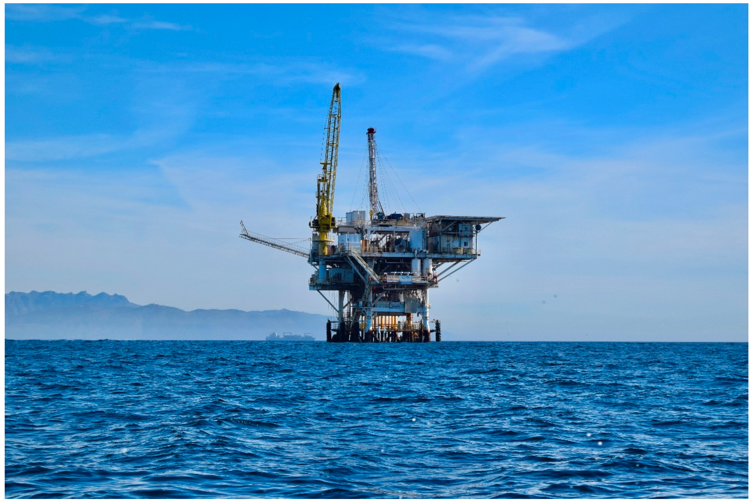
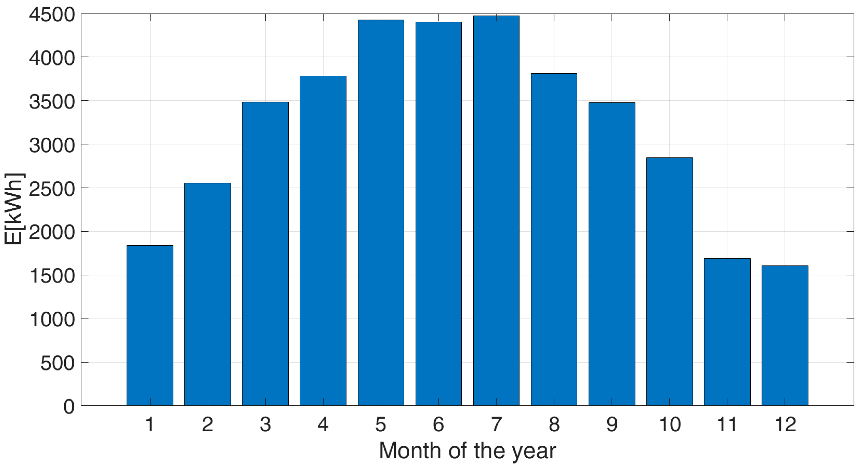
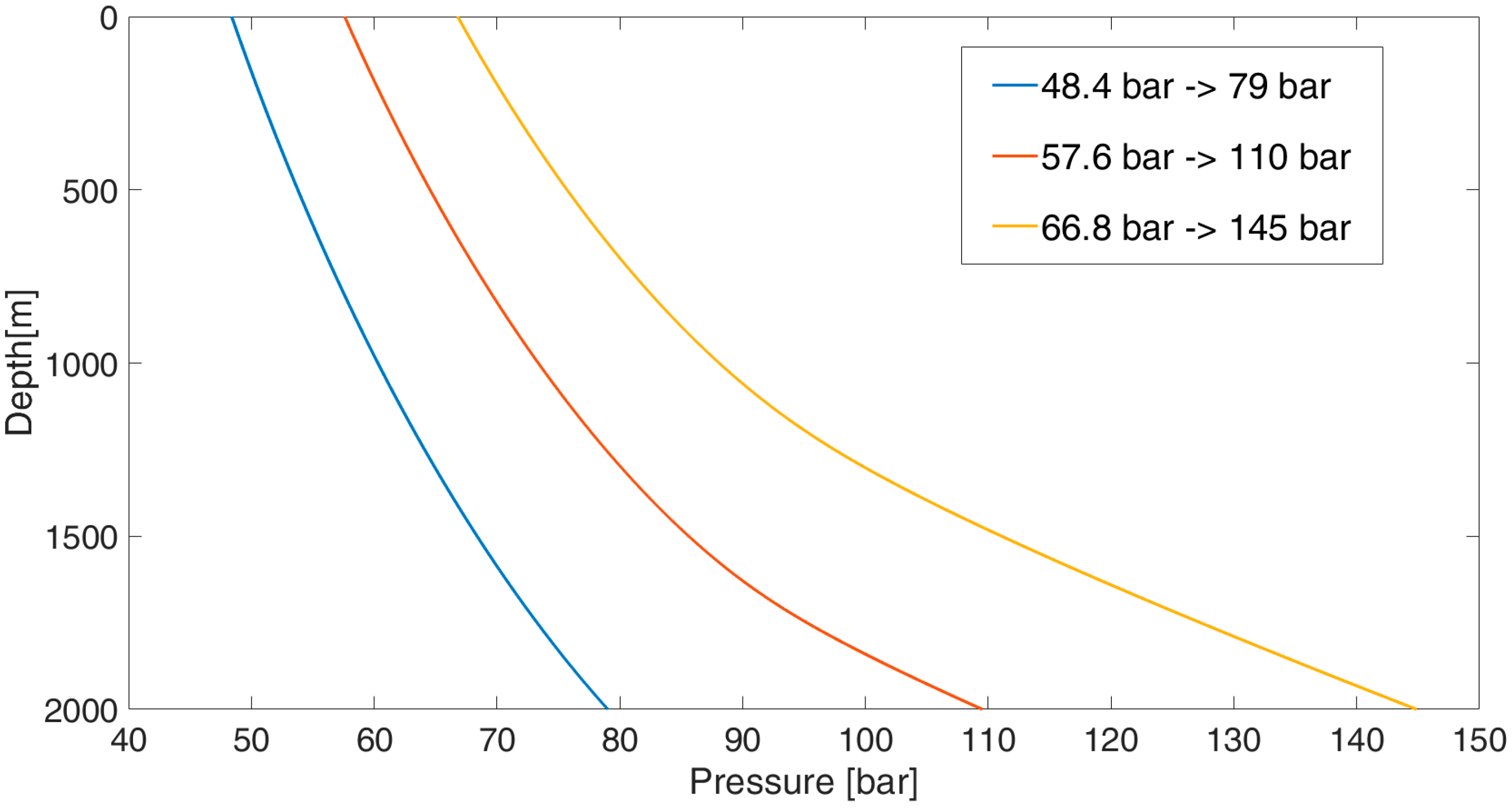


