Article

Role of the Wall Layer in 3D-Printed Composites under the Salt Spray Condition

School of Naval Architecture & Ocean Engineering, University of Ulsan, Ulsan 44610, Republic of Korea
*
Author to whom correspondence should be addressed.
J. Mar. Sci. Eng. 2023, 11(7), 1416; https://doi.org/10.3390/jmse11071416
Submission received: 19 June 2023 / Revised: 12 July 2023 / Accepted: 13 July 2023 / Published: 14 July 2023

Abstract

:
While the mechanical strength of 3D-printed composites is an area of active research, few studies have considered their application to the marine industry. In particular, the role of wall layers is an issue because of their lack of the contribution to the mechanical strength although they help prevent water penetration. In this study, experiments were performed to investigate the effects of salt spray exposure on the mechanical strength of continuous fiber 3D-printed composites with and without the wall layer. Specimens were printed using continuous fiber filaments in the same direction as the loading direction with and without a wall layer. The period of salt spray exposure was set to 15 and 30 days, and the saltwater absorption rate was calculated for each specimen. Tensile tests were performed to determine the effect of the exposure period on the tensile modulus and strength. The results showed that the tensile strength decreased with an increasing exposure period and that the presence of the wall layer reduced the rate of decrease in the mechanical strength. The results confirmed that a wall layer prevents the penetration of saltwater, which may facilitate the potential application of 3D-printed composites in the marine industry.

1. Introduction

The development of three dimensional (3D) printed composites, which combine composite materials with 3D printing technology, has been drawing attention as an important material in various industries such as shipbuilding, marine, and defense because of the various advantages offered by composite materials, such as resistance to salt and moisture and high specific strength and stiffness [1,2,3]. Because 3D printing uses additive manufacturing instead of cutting to process metallic materials, it does not require additional processes to fabricate structures, which makes designing structures with complex geometries easier than other methods [4,5,6]. However, because 3D-printed structures are typically fabricated from plastic materials without any reinforcement, their mechanical strength is limited. High-performance 3D-printed composites can be fabricated using continuous fibers to achieve high-strength reinforcement and compensate for the shortcomings of typical 3D-printed structures [7,8,9,10,11,12]. Therefore, 3D-printed composites possess the advantages of traditional composites, such as good mechanical strength and lightweight performance, and 3D printing technology, such as ease of design and fabrication of complex structures, and consistent production quality. Consequently, research and development is actively ongoing for the application of 3D-printed composites in various industries [13,14,15,16,17,18].
Li et al. [7] conducted a bending test to determine the mechanical performance of continuous carbon-fiber-reinforced PLA composites printed under a vacuum. They found that 3D printing under a vacuum reduced the degree of porosity in the specimen from 13.93% to 4.18% and increased its bending strength and bending modulus by 24.51% and 8.35%, respectively. Altug et al. [10] evaluated the mechanical performance of 3D-printed continuous fiber-reinforced thermoplastic composites (CFRTP) according to the fiber fraction. Increasing the fiber fraction in the specimen from 22% to 40% increased the tensile and bending strengths by 60.61% and 21.74%, respectively. Rashid et al. [12] evaluated the tensile strength of 3D-printed short carbon-fiber-reinforced composites according to the infill pattern and density. Their results showed that specimens with a hexagonal pattern had greater mechanical performance–weight ratio than specimens with other patterns when the density was kept constant.
While shipbuilding and offshore structures require sufficient structural strength and stiffness, they also require resistance to saltwater and ultraviolet radiation. Therefore, the effects of a saltwater environment must be investigated to realize the application of 3D-printed composites in shipbuilding and offshore industries. Various studies have focused on understanding the changes in the mechanical performance and saltwater absorption rates of conventional composite specimens after exposure to a saltwater environment [19,20,21,22,23,24,25]. Wei et al. [21] exposed glass-fiber-reinforced plastic (GFRP) and basalt-fiber-reinforced plastic (BFRP) to an artificial seawater environment (6 wt% salt) and calculated the saltwater absorption rates on Day 0, 10, 20, 30, 60, and 90. They found that the saltwater absorption rate converged on Day 30 and that the tensile strengths of the GFRP and BFRP specimens decreased after 30 days of exposure to saltwater by approximately 20% and 23%, respectively, compared to pristine specimens. Libo et al. [25] examined the tensile and bending strengths and moduli of flax fabric/epoxy composite specimens after 1 year of exposure to a saltwater environment. The tensile strength and modulus decreased by 28.3% and 27.1%, respectively, and the bending strength and modulus decreased by 18.3% and 23.5%, respectively.
For the fabrication of continuous fiber 3D-printed composites, Markforged recommends including at least two wall layers to prevent water penetration into the structure in case of exposure to moisture [26]. However, because this wall layer uses plastic filaments rather than reinforcement filaments, it does not contribute to mechanical performance. In other words, the fiber volume fraction (FVF) is lower for a specimen with a wall layer than a specimen without it. Because decreasing the FVF reduces the mechanical performance of a structure [9,10,11], including a wall layer can be considered unnecessary. However, the wall layer is necessary in the design of marine structures because it can reduce the influence of environmental conditions such as saltwater on specimen performance. Currently, the role of the wall layer in 3D-printed composites in a saltwater environment has not been sufficiently studied. However, the role of the wall layer can be predicted based on the results of other studies on its resistance against water in existing composites [27,28,29,30,31].
In this study, 3D-printed composites were tested for their mechanical strength upon exposure to saltwater. Specimens were fabricated with and without a wall layer and were then exposed to a salt spray for 15 or 30 days. The specimens were weighed to check the saltwater absorption rate, and tensile tests were carried out to determine the changes in mechanical performance. The results were used to evaluate the relationship between the decrease in mechanical performance and saltwater absorption rate and to compare the resistance of specimens to saltwater exposure with and without a wall layer.

2. Experiments

2.1. Specimen Preparation

Specimens were prepared using the X7TM 3D printer from Markforged, which uses fused deposition modeling (FDM) to melt and deposit continuous filaments and plastic filaments (Figure 1). The print bed moves in the Z-axis direction, and the nozzle moves on the XY plane according to the printing direction. The continuous fiber filaments and plastic filaments enter the heated nozzle, and they are laminated on a heated print bed in a semi-liquid state to produce composite specimens. The applied filaments for making specimens were carbon fiber continuous filament and onyx plastic filament. Onyx plastic filament is a nylon filled with micro carbon fibers. Table 1 summarizes the physical properties of carbon fiber and onyx.
Specimens were fabricated according to the ASTM D 3039 standard [33], and Figure 2 shows their shape and dimensions. An FDM-type 3D printer naturally fabricates a wall layer on the free edge of the specimen for surface finishing and fiber arrangement. In this study, two types of specimens were prepared to clarify the usefulness and mechanical behavior of the wall layer. At this time, nine specimens were prepared for each type. For type 1 specimens, the wall layer was retained, while for type 2 specimens, the wall layer was completely removed via post-processing. Both specimen types had an overall length (L) of 250 mm, width (W) of 15 mm, thickness (T) of 2 mm, and tab length (Ltab) of 56 mm. The printing direction was 0°, which was the same as the loading direction (Table 2), and 16 layers were laminated. For type 1 specimens, the wall layer was a single layer (0.4 mm) on the free edge. Type 2 specimens had an original width of more than 15.8 mm, and a part of the specimen including the wall layer was removed using a water jet to adjust the width to 15 mm (Figure 3). Figure 4 shows the cross-sections of the fabricated specimens.

2.2. Salt Spray Test

The fabricated specimens were exposed to saltwater to examine the effects of a marine environment. A salt spray test was performed using a CT-ST 600 device made by CORETECH Korea according to the ASTM B 117 standard [34]. The solution for the salt spray test was prepared with a NaCl concentration of 5% ± 1% (pH 6.5–7.2). The specimens were exposed to saltwater in the salt spray chamber, which was maintained at an internal temperature of 35 ± 2 °C.
To choose an appropriate salt spray period, the water absorption rate of conventional composite specimens exposed to a saltwater environment was analyzed [19,20,21,22,23,24,35,36]. The results of previous studies [19,20,21,22,23,24,35,36] indicated that the water absorption rate of various composite specimens converged at a critical period rather than continuously increasing with the period of exposure to freshwater/saltwater (Table 3). Water absorption was observed as most active between days 10 and 30. Thus, 15 and 30 days of exposure to saltwater were considered sufficient. In this study, the salt spray test was conducted with 15-day increments to determine the effect of the exposure period. In other words, the effects of saltwater were observed through comparing specimens before and after exposure to saltwater for 15 or 30 days. Specimens that underwent the salt spray test were labeled as Type No.-Saltwater exposure period-Specimen No. The saltwater absorption rate (W) of 3D-printed composite specimens exposed to saltwater was calculated according to the ASTM D 570 standard [37]:
W ( % ) = W t W 0 W 0 × 100
where W t is the weight of a specimen exposed to a saltwater environment for the period t and W 0 is the weight of the specimen before it was exposed to the saltwater environment.

2.3. Tensile Test

A tensile test was performed according to the ASTM D 3039 standard [33] to evaluate the tensile strength of the specimens after exposure to the saltwater environment. The tensile test was performed using the universal testing machine (UTM) DTU-900MH from Daekyung Tech, which has a load cell capacity of 300 kN. The displacement speed was 2 mm/min, and the test continued until a specimen fractured. Three groups of specimens were tested at a laboratory temperature of 24–26 °C and were divided according to the period of saltwater exposure: 0 days, 15 days in the salt spray test, and 30 days in the salt spray test.

3. Results

3.1. Saltwater Absorption Rate

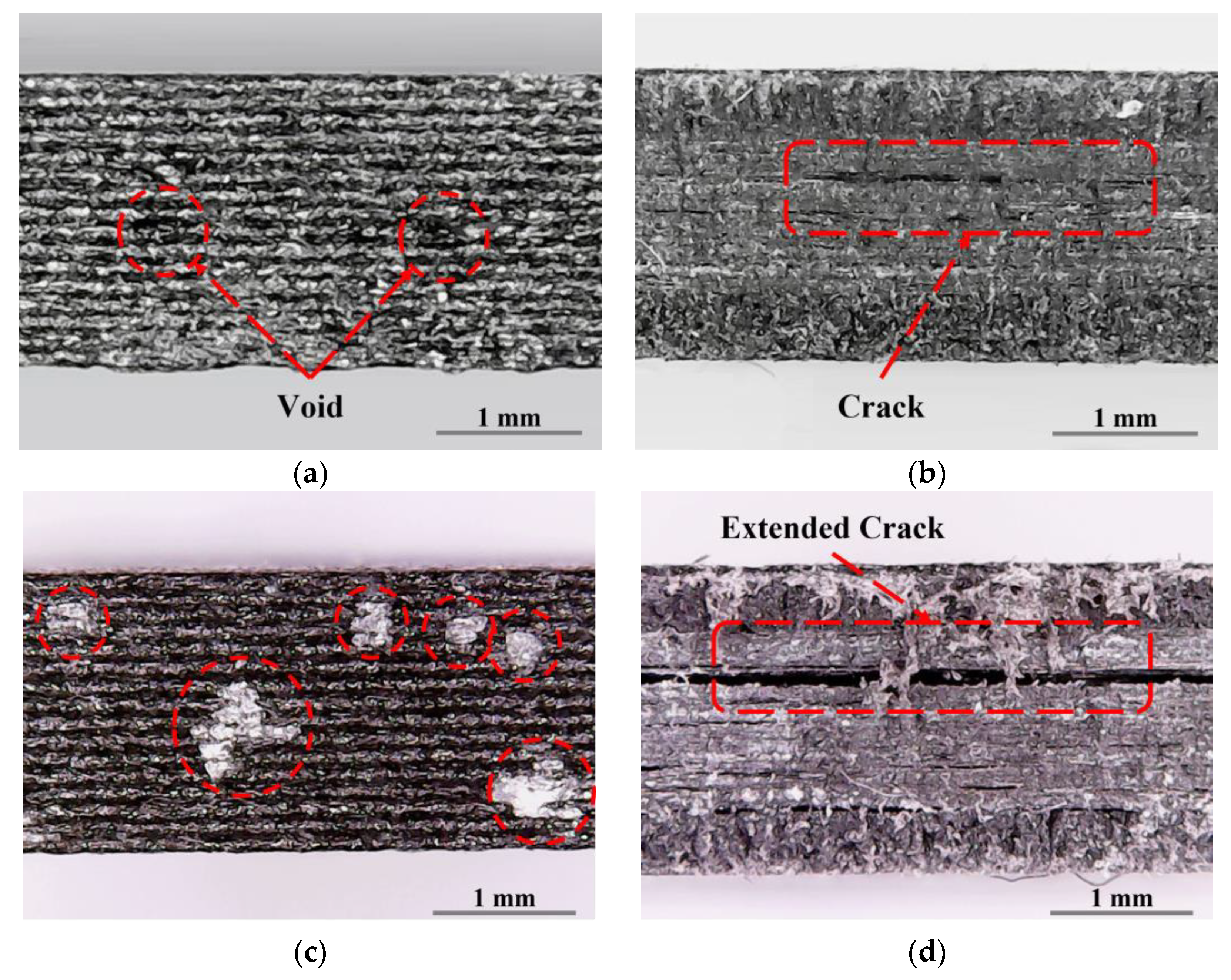
The weights of the 0-day (i.e., dry) specimens were used to calculate the saltwater absorption rates of the specimens after 15 and 30 days of saltwater exposure according to Equation (1). The results are summarized in Table 4. The weight of specimens exposed to saltwater increased with the exposure period, regardless of the specimen type. This is because saltwater penetrates the voids created during the fabrication of the specimen and the cracks created during post-processing at the macro level, as shown in Figure 5a,b [24,38]. This result can also be attributed to saltwater invading the interlaminar separation zone caused by the decrease in interfiber adhesion strength, as shown in Figure 5c,d [21,25]. As the exposure period increased, more saltwater penetrated the space created by molecular penetration [21,24,25,38]. However, as the specimens continue to absorb more saltwater, they are eventually saturated. Therefore, this phenomenon causes the saltwater absorption rate to converge at a critical exposure period.
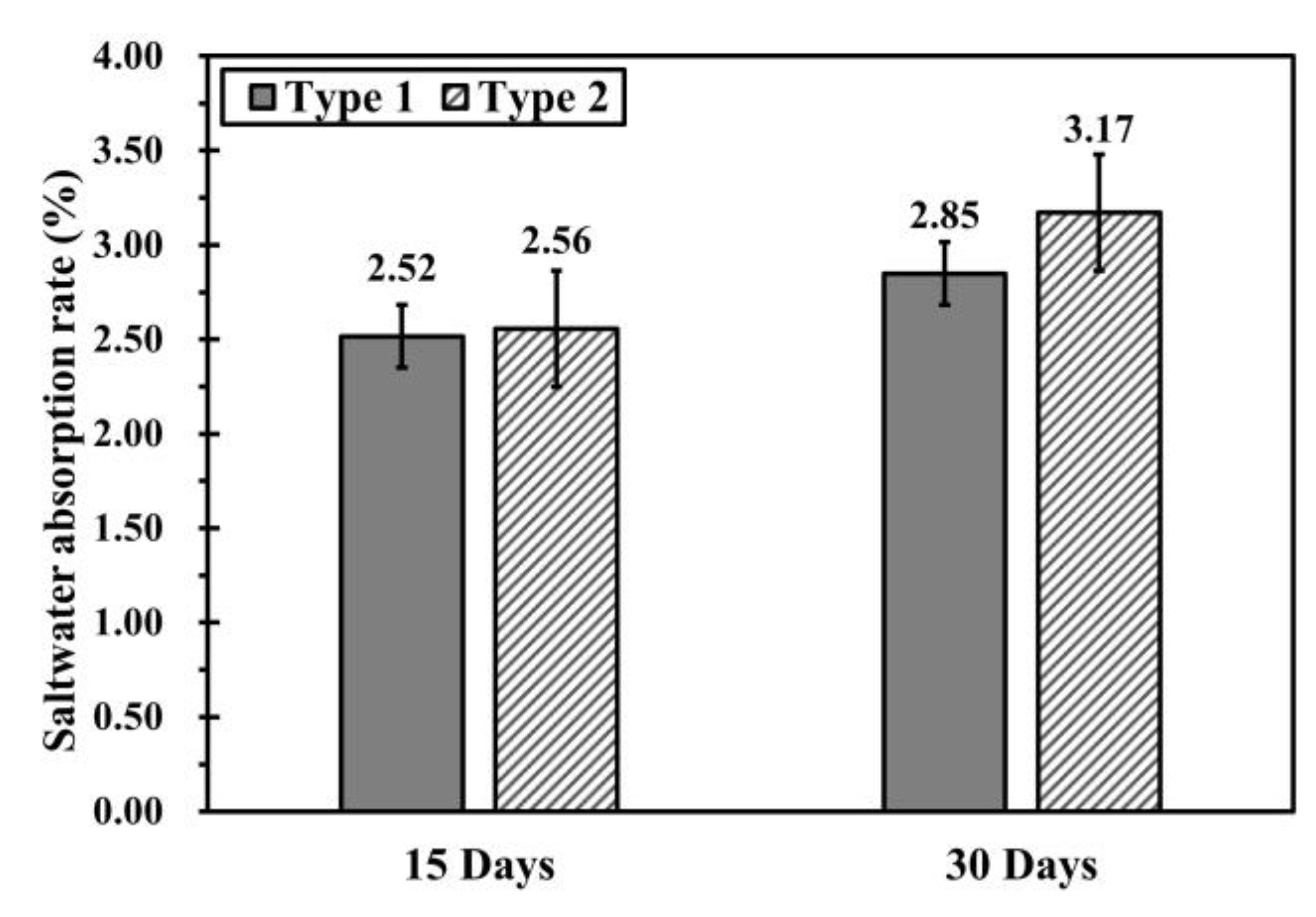
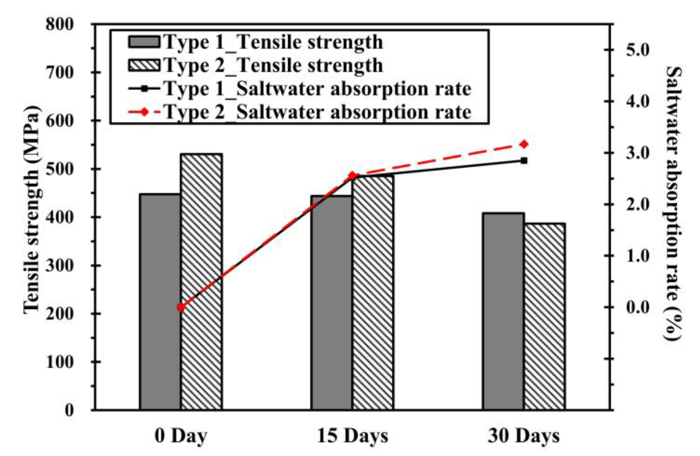
Figure 6 shows the saltwater absorption rates of specimens according to exposure period and specimen type. At 15 days of exposure, the saltwater absorption rates of the type 1 and 2 specimens were 2.52% and 2.56%, respectively, which is a negligible difference. At 30 days of exposure, the saltwater absorption rates were 2.85% and 3.17%, respectively. The difference was approximately 0.3%, which was eightfold greater than the difference observed between specimens with 15 days of exposure. Although saltwater did penetrate the wall layers of the type 1 specimens, the increase in the saltwater absorption rate was negligible because the wall layers prevented further penetration. On the other hand, the type 2 specimens lacked a wall layer, which allowed saltwater to penetrate the cracks and voids between the layers more actively.

3.2. Tensile Properties

3.2.1. Tensile Strength

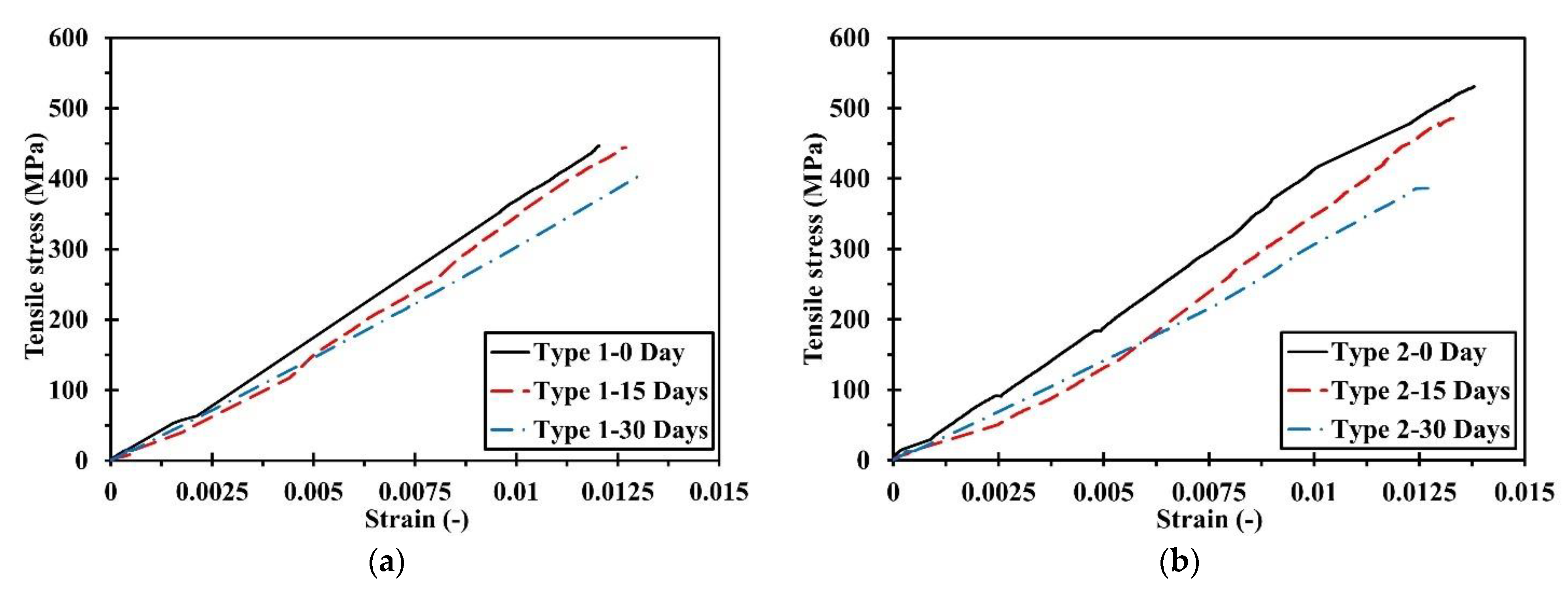
Figure 7 presents the tensile behaviors of the specimens when exposed to saltwater for different periods. Both types of specimens demonstrated the same linear behavior until fracture, and specimens not exposed to saltwater showed the highest tensile strength. The tensile strength decreased as the exposure period increased. These results indicated that the saltwater environment influenced the tensile strength of the specimens. Figure 8 compares the experimental results of type 1 and 2 specimens (i.e., with and without a wall layer, respectively) when exposed to saltwater for the same period. Before exposure, the type 1 and type 2 specimens had tensile strengths of 447.48 and 530.77 MPa, respectively (Figure 8a). Thus, the type 2 specimens were 119% stronger than the type 1 specimens were. After 15 days of exposure, the tensile strengths were 444.01 and 485.29 MPa, respectively (Figure 8b). Thus, the type 2 specimens were 109% stronger than the type 1 specimens. These results can be attributed to the difference in the FVFs of the two types. A higher FVF means that more fibers are available to support the load. Therefore, a specimen with a higher FVF has more tensile strength [9,11]. The type 1 specimens had an FVF of 47%, while the type 2 specimens had an FVF of 50%, which explains why the latter had a higher tensile strength. However, after 30 days of exposure, the type 1 and type 2 specimens had tensile strength of 408.34 and 386.33 MPa, respectively (Figure 8c). Unlike the previous results, the type 2 specimens had 94.6% of the tensile strength of the type 1 specimens. This indicates that the applied wall layer contributes to mechanical performance more critically than FVF after a salt spray test.
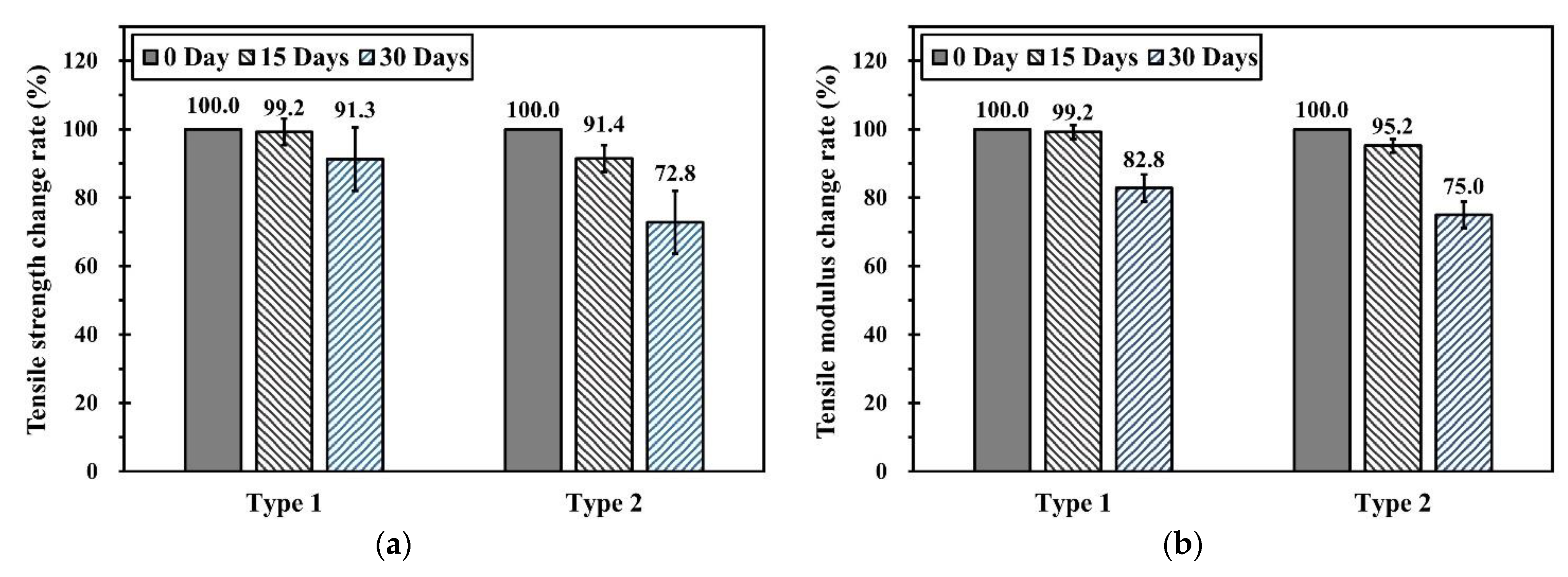
Figure 9 shows the change in mechanical performance of specimens according to the saltwater exposure period. Saltwater exposure decreased the mechanical performance of the specimens with and without the wall layer. The tensile strength and modulus of the type 2 specimens (i.e., without the wall layer) decreased more than those of the type 1 specimens (i.e., with the wall layer). The difference in tensile properties was smaller between specimens exposed to saltwater for 15 days than between those before exposure. After 30 days of exposure, the type 1 specimens showed greater tensile strength than the type 2 specimens, which is in contrast to the previous results. The presence of the wall layer may be an important factor for explaining the difference in mechanical performance degradation during the same period of saltwater exposure. As shown in Figure 5, saltwater penetrated the cracks and voids between the layers of the specimens upon exposure. However, the effects of saltwater were reduced in the type 1 specimens because the wall layer prevented further penetration. The type 2 specimens were more affected because there was no wall layer to prevent saltwater penetration between the onyx and carbon fiber layers.

3.2.2. Relationship between the Saltwater Absorption Rate and Tensile Strength

Table 5 summarizes the results of the salt spray test and tensile test. For both types of specimens, increasing the saltwater exposure period increased the saltwater absorption rate and decreased the tensile modulus and strength. The coefficient of variation (CV) was greater for the type 2 specimens than for the type 1 specimens, which can be attributed to the damage occurred to the former during post-processing. Among type 2 specimens, the CV decreased upon 30 days of exposure of saltwater, which is because the damage caused by the saltwater exposure affected the test results more than the damage caused by the post-processing. Especially, the failure near the tab was investigated in type 1 specimens. Table 6 exhibits the comparisons of the average tensile strength between all specimens and the specimens without tab failure for type 1. When examining these values, the difference in tensile strength is only 0.24% to 1.24%. In the case of specimens that failed near the tab, cracks started near the tab due to stress concentration, and the final fracture occurred as the crack propagated as the tensile load was applied [39,40]. Figure 10 shows the relationship between the tensile strength and saltwater absorption rate, which was different among the specimen types. For the type 1 specimens, increasing the saltwater exposure period resulted in a relatively small increase in the saltwater absorption rate and a negligible decrease in the tensile strength. For the type 2 specimens, increasing the saltwater exposure period resulted in a relatively high saltwater absorption rate and a noticeably larger decrease in the tensile strength. These results confirmed that saltwater exposure decreased the tensile strength and modulus of the specimens, but the extent of the decrease depended on the presence of a wall layer.
A saltwater environment can have a range of effects on specimens made of composite materials [21,24,25,38,41]. The mechanical performance degrades from plasticization of the matrix, deterioration of the chemical and physical properties of the fibers and matrix, generation of swelling and internal stresses, enlargement of voids and cracks due to water and molecular penetration, and debonding phenomena due to decreased bond strength between the fibers and matrix. In saltwater, NaCl exists in cationic (Na+) and anionic (Cl) states, which penetrate the composite together with water molecules (H2O) and damage the matrix, fibers, and fiber–matrix interface [24,38].
In the present study, saltwater penetrated the voids and cracks generated from the fabrication and post-processing of specimens, as shown in Figure 5a,b. Saltwater penetration adversely affected the mechanical properties of the specimens [38,41] and caused more physical and chemical degradation as the exposure period increased [21,38]. The infused saltwater settled and the saltwater dried and crystallized inside the specimens. Crystals formed inside generate internal tensile stresses, which expanded the voids and cracks as shown in Figure 5c,d to degrade the bonding strength of the fiber–matrix interface [25] and cause debonding.
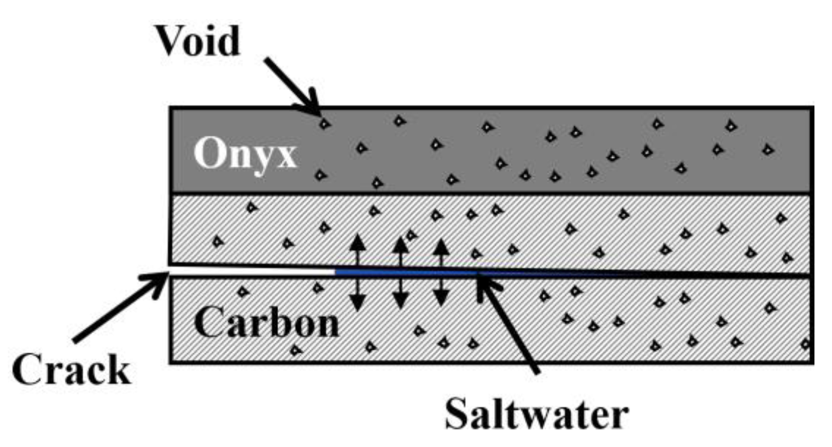
Figure 11 shows that the saltwater penetrated the specimen and expanded the voids and cracks, which provided additional space for the saltwater to penetrate. Thus, the saltwater absorption rate increased with the saltwater exposure period. As the size of the voids and cracks increased, the bond strength between the fibers and matrix at the fiber–matrix interface decreased. The decreased bond strength caused delamination in the specimens, which reduced the tensile strength. Because the type 1 specimens had a wall layer, penetration of saltwater was poor, and the degradation of the tensile properties was not large. In contrast, the type 2 specimens had no wall layer, so the penetration of saltwater was easier, yielding a relatively large degradation of the tensile properties. Thus, the presence of a wall layer affected the saltwater absorption rate, which had a major impact on the degradation of mechanical properties.

3.3. Failure Mode

The failure modes of the specimens in the tensile test were analyzed to determine the impact of the saltwater environment. Specimens exposed to a saltwater environment can experience a change in failure mode. Table 7 presents the codes for various failure modes as specified in the standard ASTM D3039 [33]. The codes comprise three characters, where the first character represents the failure type, the second character represents the failure area, and the third character represents the failure location. The failure type is the most important piece of information about the specimen and is related to the mechanical performance. A lateral (L) failure occurs when the fibers break because they cannot support the applied tensile load [42]. An angled (A) failure occurs when a specimen subjected to a tensile load is fractured at an angle due to shear stress [43]. The crack caused by the tensile load propagates and causes a displacement difference between layers. An edge delamination (D) failure is caused by the debonding from this displacement difference, which leads to a final fracture [44,45,46]. A grip/tab (G) failure occurs when the adhesive used to attach the specimen and tab cannot withstand the tensile load, which leads to a phenomenon such as slip [33]. An explosive (X) failure occurs with stepwise debonding between the fibers, matrix, and fiber–matrix interface, leading to the failure of fibers [42].
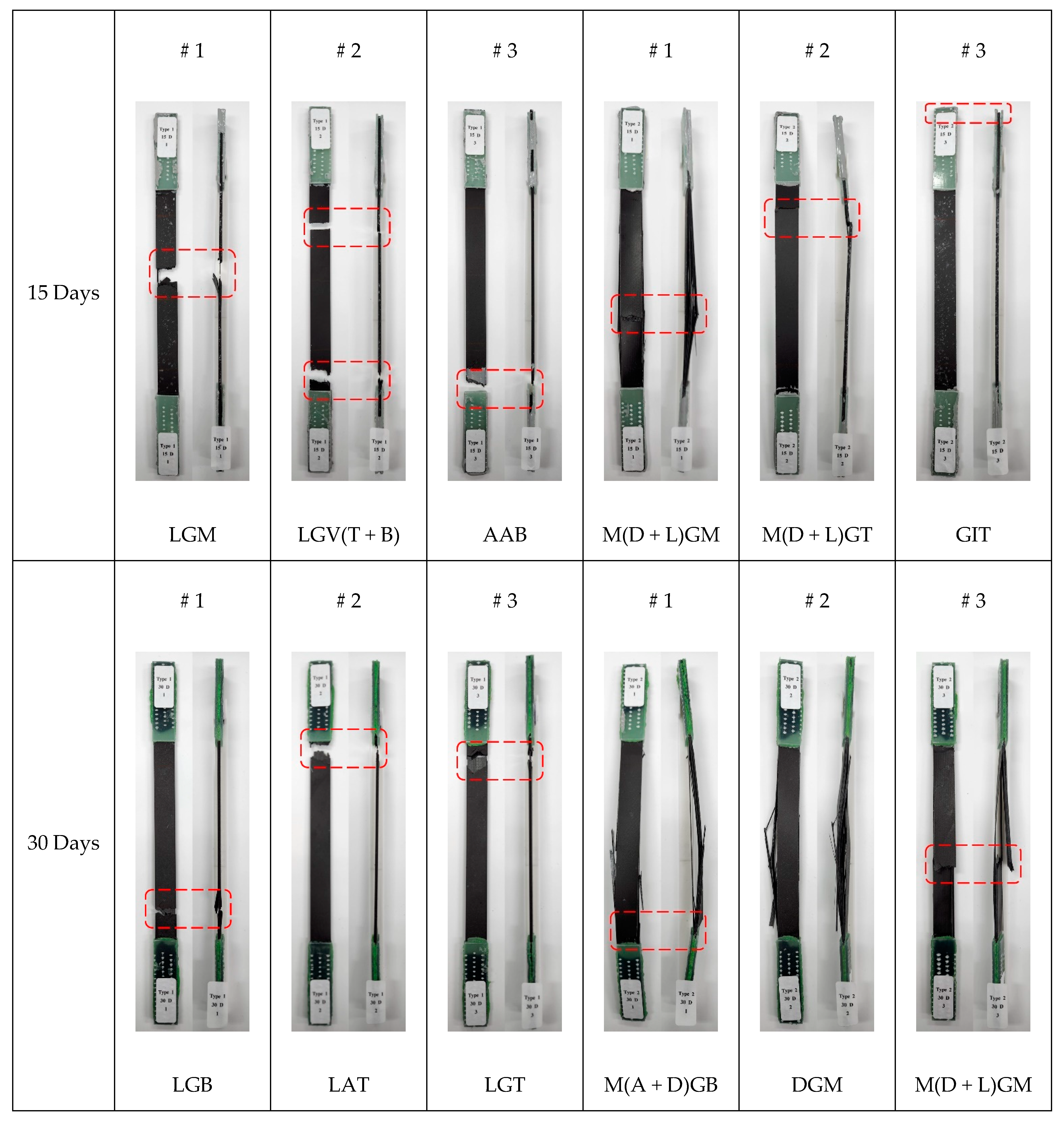
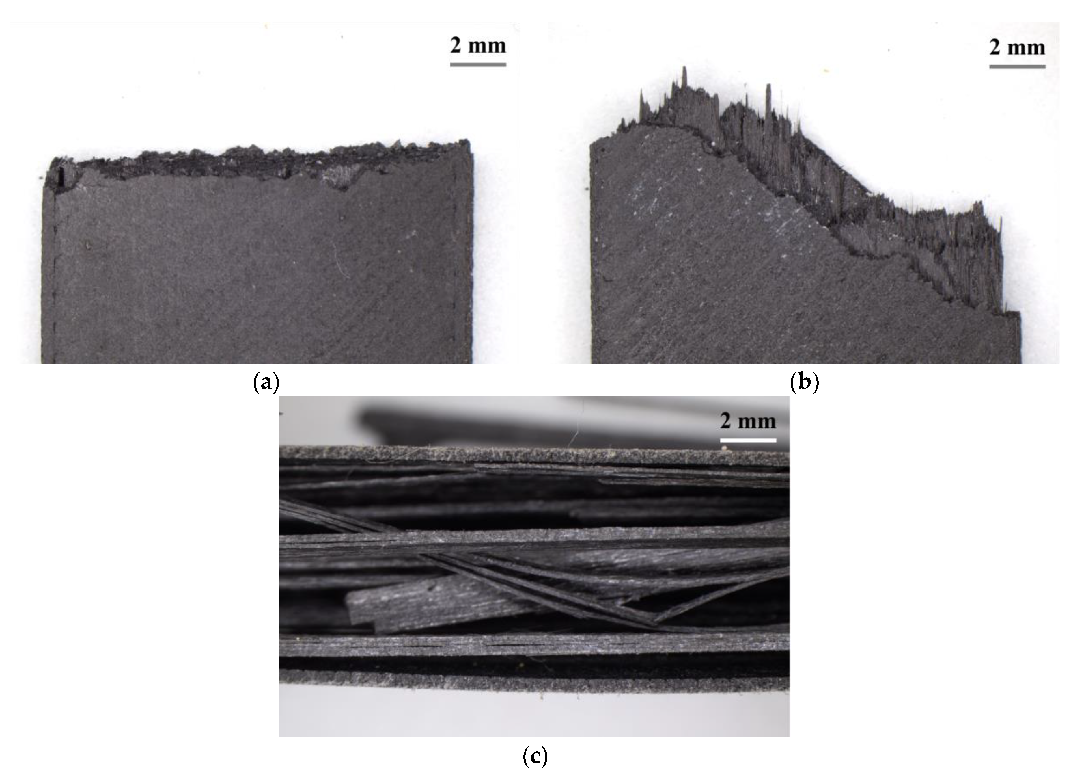
Figure 12 shows images of considerably damaged specimens after the tensile test. Also, as seen in Figure 13, the three significant failure types were investigated using a microscope. The effects of saltwater were analyzed through examining the failure modes of the specimens. The type 1 specimens mainly had L or A failure types regardless of the duration of saltwater exposure. These failure types occur when the fibers fail under a tensile load or the specimen fractures at an angle due to shear stress. The type 1 specimens retained 99.2% of their initial strength after 15 days of saltwater exposure (0.8% decrease) and 91.3% after 30 days of exposure (8.7% decrease). The degradation of tensile strength is trivial compared to that of the type 2 specimens, which can be attributed to the wall layer preventing penetration of saltwater. For the type 2 specimens, the main failure type changed from L to D upon saltwater exposure. As shown in Figure 5, the type 2 specimens developed cracks during post-processing performed for the removal of the wall layer. The exposure to saltwater contributed to the propagation of the cracks. In addition, application of a tensile load caused debonding owing to the displacement difference between the layers. This explains the change in failure type from L to D. The type 2 specimens retained 91.4% of their initial strength after 15 days of saltwater exposure (8.6% decrease) and 72.8% after 30 days of exposure (27.2% decrease), which can be attributed to the easier penetration of saltwater owing to the absence of a wall layer. Consequently, expanded voids and cracks weakened the adhesion of fibers, matrix, and the fiber–matrix interface.

4. Conclusions

This study evaluated the usefulness of a wall layer in 3D-printed composites for applications in a saltwater environment. Two types of specimens were fabricated—with and without a wall layer. The effects of the duration of saltwater exposure on the saltwater absorption rate, tensile strength, and failure mode were evaluated through experiments.
  • Type 1 specimens showed a smaller increase in the saltwater absorption rate than the type 2 specimens. The difference in saltwater absorption rates was negligible at 15 days of exposure but was substantial at 30 days of exposure.
  • For a given specimen type, the tensile strength decreased as the duration of saltwater exposure increased. The decrease in tensile strength was less for the type 1 specimens than for the type 2 specimens.
  • A faster saltwater absorption rate resulted in more degradation of tensile strength. The tensile strength degradation was less for specimens with 15 days of saltwater exposure than for those with 30 days of saltwater exposure.
  • The type 1 specimens mainly demonstrated A and L failure types regardless of the duration of saltwater exposure. Pristine type 2 specimens before any saltwater exposure also demonstrated the L failure type. However, saltwater exposure to type 2 specimens changed their failure type to D.
The results demonstrated that increasing the duration of saltwater exposure decreased the tensile strength of the specimens, but the presence of a wall layer effectively mitigated the effects of saltwater penetration. Thus, the wall layer should be retained in 3D-printed composite materials for fabricating structures that are expected to be exposed to a saltwater environment such as ships and offshore structures.

Author Contributions

Conceptualization, D.-H.K. and H.-S.S.; methodology, H.-S.S.; validation, H.-S.S.; formal analysis, D.-H.K. and H.-S.S.; investigation, D.-H.K.; writing—original draft preparation, D.-H.K.; writing—review and editing, H.-S.S.; visualization, D.-H.K.; supervision, H.-S.S.; project administration, H.-S.S.; funding acquisition, H.-S.S. All authors have read and agreed to the published version of the manuscript.

Funding

This research was funded by the Unmanned Vehicles Core Technology Research and Development Program through the National Research Foundation of Korea (NRF) and Unmanned Vehicle Advanced Research Center (UVARC) funded by the Ministry of Science and ICT, the Republic of Korea (NRF-2020M3C1C1A01084221).

Acknowledgments

The authors would like to thank the anonymous reviewers for their constructive suggestions, which comprehensively improved the quality of the paper.

Conflicts of Interest

The authors declare no conflict of interest.

References

  1. Nachtane, M.; Tarfaoui, M.; Abichou, M.A.; Vetcher, A.; Rouway, M.; Aâmir, A.; Mouadili, H.; Laaouidi, H.; Naanani, H. An overview of the recent advances in composite materials and artificial intelligence for hydrogen storage vessels design. J. Compos. Sci. 2023, 7, 119. [Google Scholar] [CrossRef]
  2. Pastuszak, P.D.; Muc, A. Application of composite materials in modern constructions. Key Eng. Mater. 2013, 542, 119–129. [Google Scholar] [CrossRef]
  3. Kim, D.U.; Seo, H.S.; Jang, H.Y. Study on mechanical bearing strength and failure modes of composite materials for marine structures. J. Mar. Sci. Eng. 2021, 9, 726. [Google Scholar] [CrossRef]
  4. Murdy, P.; Dolson, J.; Miller, D.; Hughes, S.; Beach, R. Leveraging the advantages of additive manufacturing to produce advanced hybrid composite structures for marine energy systems. Appl. Sci. 2021, 11, 1336. [Google Scholar] [CrossRef]
  5. Ford, S.; Despeisse, M. Additive manufacturing and sustainability: An exploratory study of the advantages and challenges. J. Clean. Prod. 2016, 137, 1573–1587. [Google Scholar] [CrossRef]
  6. Perry, A. 3D-printed apparel and 3D-printer: Exploring advantages, concerns, and purchases. Int. J. Fash Technol. Educ. 2018, 11, 95–103. [Google Scholar] [CrossRef] [Green Version]
  7. Li, H.; Liu, B.; Ge, L.; Chen, Y.; Zheng, H.; Fang, D. Mechanical performances of continuous carbon fiber reinforced PLA composites printed in vacuum. Compos. B Eng. 2021, 225, 109277. [Google Scholar] [CrossRef]
  8. Saeed, K.; McIlhagger, A.; Harkin-Jones, E.; Kelly, J.; Archer, E. Predication of the in-plane mechanical properties of continuous carbon fibre reinforced 3D printed polymer composites using classical laminated-plate theory. Compos. Struct. 2021, 259, 113226. [Google Scholar] [CrossRef]
  9. Hetrick, D.R.; Sanei, S.H.R.; Bakis, C.E.; Ashour, O. Evaluating the effect of variable fiber content on mechanical properties of additively manufactured continuous carbon fiber composites. J. Reinf. Plast. Compos. 2020, 40, 365–377. [Google Scholar] [CrossRef]
  10. Uşun, A.; Gümrük, R. The mechanical performance of the 3D printed composites produced with continuous carbon fiber reinforced filaments obtained via melt impregnation. Addit. Manuf. 2021, 46, 102112. [Google Scholar] [CrossRef]
  11. Saeed, K.; McIlhagger, A.; Harkin-Jones, E.; McGarrigle, C.; Dixon, D.; Ali Shar, M.; McMillan, A.; Archer, E. Characterization of continuous carbon fibre reinforced 3D printed polymer composites with varying fibre volume fractions. Compos. Struct. 2022, 282, 115033. [Google Scholar] [CrossRef]
  12. Al Rashid, A.A.; Ikram, H.; Koç, M. Additive manufacturing and mechanical performance of carbon fiber reinforced Polyamide-6 composites. Mater. Today Proc. 2022, 62, 6359–6363. [Google Scholar] [CrossRef]
  13. Froes, F. Combining additive manufacturing with conventional casting and reduced density materials to greatly reduce the weight of airplane components such as passenger seat frames. In Additive Manufacturing for the Aerospace Industry, 1st ed.; Froes, F., Boyer, R., Eds.; Elsevier Inc.: Amsterdam, The Netherlands, 2019; pp. 419–425. [Google Scholar] [CrossRef]
  14. Sangiuliano, L.; Reff, B.; Palandri, J.; Wolf-Monheim, F.; Pluymers, B.; Deckers, E.; Desmet, W.; Claeys, C. Low frequency tyre noise mitigation in a vehicle using metal 3D printed resonant metamaterials. Mech. Syst. Signal Process. 2022, 179, 109335. [Google Scholar] [CrossRef]
  15. Muralidharan, N.; Pratheep, V.G.; Shanmugam, A.; Hariram, A.; Dinesh, P.; Visnu, B. Structural analysis of mini drone developed using 3D printing technique. Mater. Today Proc. 2021, 46, 8748–8752. [Google Scholar] [CrossRef]
  16. Chen, L.; Zhang, Y.; Chen, Z.; Xu, J.; Wu, J. Topology optimization in lightweight design of a 3D-printed flapping-wing micro aerial vehicle. Chin. J. Aeronaut. 2020, 33, 3206–3219. [Google Scholar] [CrossRef]
  17. Jeong, D.G.; Seo, H.S. Study on mechanical performance of 3D printed composite material with topology shape using finite element method. Funct. Compos. Struct. 2021, 3, 035003. [Google Scholar] [CrossRef]
  18. Kalsoom, U.; Nesterenko, P.N.; Paull, B. Recent developments in 3D printable composite materials. RSC Adv. 2016, 6, 60355–60371. [Google Scholar] [CrossRef]
  19. Yang, B.; Zhang, J.; Zhou, L.; Lu, M.; Liang, W.; Wang, Z. Effect of fiber surface modification on water absorption and hydrothermal aging behaviors of GF/pCBT composites. Compos. B Eng. 2015, 82, 84–91. [Google Scholar] [CrossRef]
  20. Ronagh, H.; Saeed, N. Changes in mechanical properties of GFRP composite after exposure to warm seawater. J. Compos. Mater. 2016, 51, 2733–2742. [Google Scholar] [CrossRef]
  21. Wei, B.; Cao, H.; Song, S. Degradation of basalt fibre and glass fibre/epoxy resin composites in seawater. Corros. Sci. 2011, 53, 426–431. [Google Scholar] [CrossRef]
  22. Ding, A.; Wang, J.; Ni, A.; Li, S. Assessment on the ageing of sandwich composites with vinylester-based composite faces and PVC foam core in various harsh environments. Compos. Struct. 2019, 213, 71–81. [Google Scholar] [CrossRef]
  23. Batista, N.L.; Rezende, M.C.; Botelho, E.C. The influence of crystallinity on the weather resistance of CF/PEEK composites. Appl. Compos. Mater. 2021, 28, 235–246. [Google Scholar] [CrossRef]
  24. Fiore, V.; Scalici, T.; Calabrese, L.; Valenza, A.; Proverbio, E. Effect of external basalt layers on durability behaviour of flax reinforced composites. Compos. B Eng. 2016, 84, 258–265. [Google Scholar] [CrossRef]
  25. Yan, L.; Chouw, N. Effect of water, seawater and alkaline solution ageing on mechanical properties of flax fabric/epoxy composites used for civil engineering applications. Constr. Build. Mater. 2015, 99, 118–127. [Google Scholar] [CrossRef]
  26. Markforged. Available online: https://markforged.com/ (accessed on 18 June 2023).
  27. Praveen, B.M.; Venkatesha, T.V. Generation and corrosion behavior of Zn-nanosized carbon black composite coating. Int. J. Electrochem. Sci. 2009, 4, 258–266. [Google Scholar] [CrossRef]
  28. Wang, H.; Zhu, S.; Yao, H.; Di, Y.; Shu, M.; Li, J.; Zhang, B.; Cao, G.; Guan, S. Positive effect of the addition of polyaniline on the anticorrosive property of polyethersulfone two-layer composite coating. J. Appl. Polym. Sci. 2021, 138, 50758. [Google Scholar] [CrossRef]
  29. Atta, A.M.; Al-Lohedan, H.A.; El-Saeed, A.M.; Al-Shafey, H.I.; Wahby, M.H. Epoxy embedded with TiO2 nanogel composites as promising self-healing organic coatings of steel. Prog. Org. Coat. 2017, 105, 291–302. [Google Scholar] [CrossRef]
  30. Bagherzadeh, M.R.; Mahdavi, F. Preparation of epoxy–clay nanocomposite and investigation on its anti-corrosive behavior in epoxy coating. Prog. Org. Coat. 2007, 60, 117–120. [Google Scholar] [CrossRef]
  31. Zhang, Z.; Zhao, N.; Qi, F.; Zhang, B.; Liao, B.; Ouyang, X. Reinforced superhydrophobic anti-corrosion epoxy resin coating by fluorine–silicon–carbide composites. Coatings 2020, 10, 1244. [Google Scholar] [CrossRef]
  32. Markforged Material Data Sheet 2022, 20 January 2022. Available online: https://markforged.com/materials/ (accessed on 18 June 2023).
  33. American Society for Testing and Materials. Standard Test Method for Tensile Properties of Polymer Matrix Composite Materials (ASTM D3039/D3039M-17); ASTM International: West Conshohocken, PA, USA, 2017. [Google Scholar]
  34. American Society for Testing and Materials. Standard Practice for Operating Salt Spray(Fog) Apparatus (ASTM B117-19); ASTM International: West Conshohocken, PA, USA, 2019. [Google Scholar]
  35. Fiore, V.; Scalici, T.; Calabrese, L.; Valenza, A.; Bella, G.L. Durability of Flax-Basalt hybrid composites for marine applications. In Proceedings of the 20th International Conference on Composite Materials, Copenhagen, Denmark, 19–24 July 2015. [Google Scholar]
  36. Korach, C.S.; Chiang, F.P. Characterization of carbon fiber-vinylester composites exposed to combined UV radiation and salt spray. In Proceedings of the 15th European conference on composite materials, Venice, Italy, 24–28 June 2012. [Google Scholar]
  37. American Society for Testing and Materials. Standard Test Method for Water Absorption of Plastics (ASTM D570-22); ASTM International: West Conshohocken, PA, USA, 2022. [Google Scholar]
  38. Fiore, V.; Calabrese, L.; Proverbio, E.; Passari, R.; Valenza, A. Salt spray fog ageing of hybrid composite/metal rivet joints for automotive applications. Compos. B Eng. 2017, 108, 65–74. [Google Scholar] [CrossRef]
  39. Mohammadizadeh, M.; Fidan, I. Tensile Performance of 3D-Printed Continuous Fiber-Reinforced Nylon Composites. J. Manuf. Mater. Process. 2021, 5, 68. [Google Scholar] [CrossRef]
  40. Kumar Mishra, P.; Jagadesh, T. Investigation into tensile behavior of 3D printed nylon-based low and high-volume fraction carbon fiber composite. Rapid Prototyp. J. 2023. ahead-of-print. [Google Scholar] [CrossRef]
  41. Gellert, E.P.; Turley, D.M. Seawater immersion ageing of glass-fibre reinforced polymer laminates for marine applications. Compos. Part A Appl. Sci. Manuf. 1999, 30, 1259–1265. [Google Scholar] [CrossRef]
  42. Muflikhun, M.A.; Fiedler, B. Failure prediction and surface characterization of GFRP laminates: A study of stepwise loading. Polymers 2022, 14, 4322. [Google Scholar] [CrossRef] [PubMed]
  43. Mahmud, J.; Hussain, A.K.; Rahimi, N.; Rahim, M.A. Failure analysis of composite laminate based on experiment-simulation integration. CREAM Curr. Res. 2013, 2, 7–22. [Google Scholar]
  44. Muflikhun, M.A.; Yokozeki, T. Systematic analysis of fractured specimens of composite laminates: Different perspectives between tensile, flexural, Mode I, and Mode II test. Int. J. Lightweight Mater. Manuf. 2023, 6, 329–343. [Google Scholar] [CrossRef]
  45. Wu, X.F.; Dzenis, Y.A. Experimental determination of probabilistic edge-delamination strength of a graphite–fiber/epoxy composite. Compos. Struct. 2005, 70, 100–108. [Google Scholar] [CrossRef] [Green Version]
  46. Behera, R.P.; Rawat, P.; Singh, K.K. Tensile behavior of three phased glass/epoxy laminate embedded with MWCNTs: An experimental approach. Mater. Today Proc. 2018, 5, 8176–8183. [Google Scholar] [CrossRef]
Figure 1. Schematic of 3D printing using the fused deposition modeling (FDM) method.
Jmse 11 01416 g001
Figure 2. Dimensions of a 3D-printed composite specimen.
Jmse 11 01416 g002
Figure 3. Markforged S/W Eiger images of specimens: (a) type 1 and (b) type 2.
Jmse 11 01416 g003
Figure 4. Cross-sections of 3D-printed composite specimens: (a) type 1 and (b) type 2.
Jmse 11 01416 g004
Figure 5. Microscopic view of specimens’ sides: (a) type 1 and (b) type 2 before the salt spray test; (c) type 1 and (d) type 2 after 30 days of the salt spray test.
Jmse 11 01416 g005
Figure 6. Comparison of saltwater absorption rates for different specimens and exposure periods.
Jmse 11 01416 g006
Figure 7. Tensile stresses of specimens according to exposure period: (a) type 1 and (b) type 2.
Jmse 11 01416 g007
Figure 8. Tensile stresses of specimens according to type: (a) 0 days, (b) 15 days, and (c) 30 days.
Jmse 11 01416 g008
Figure 9. Changes in mechanical performance of type 1 and type 2 specimens: (a) tensile strength and (b) modulus.
Jmse 11 01416 g009
Figure 10. Relationship between the saltwater absorption rate and tensile strength.
Jmse 11 01416 g010
Figure 11. Schematic of expansion of cracks and voids.
Jmse 11 01416 g011
Figure 12. Failure modes of 3D-printed composite specimens.
Jmse 11 01416 g012aJmse 11 01416 g012b
Figure 13. Microscopic image of significant failure types: (a) lateral failure type, (b) angled failure type, and (c) edge delamination failure type.
Jmse 11 01416 g013
Table 1. Material properties [32].
PropertyCarbon FiberOnyx
Tensile modulus (GPa)602.4
Tensile strength (MPa)80040
Tensile strain (%)1.525
Test (ASTM)D 3039D 638
Table 2. Laminate information of 3D-printed composite specimens.
TypeMaterialPrinting DirectionTotal Layer NO.Total Layer Thickness (mm)
Type 1
(With wall layer)
Onyx[±45°]240.5
Carbon fiber[0°]881.0
Onyx[±45°]240.5
Onyx(Wall layer)-162.0
Type 2
(Without wall layer)
Onyx[±45°]240.5
Carbon fiber[0°]881.0
Onyx[±45°]240.5
Table 3. Summary of critical periods.
Concentration of SolutionConditioned Temperature (°C)MaterialCritical Period (Days)Ref.
Water25, 60GF/pCBT composite25[19]
Seawater60GFRP composite10[20]
Artificial seawater
(6 wt.% salt)
25BFRP, GFRP composite30[21]
3.5% NaCl35Vinylester-based composite12.5[22]
5% NaCl1, 10CF/PEEK composite25[23]
35Flax–Basalt FRP composite25[24]
35Flax–Basalt FRP composite25[35]
35CF/Vinylester composite17[36]
Table 4. Summary of salt spray test results.
TypeExposure Period
(Days)
Weight (g)Weight Variation
(g)
Saltwater Absorption
Ratio (%)
BeforeAfter
Type 1
(With wall layer)
08.878.8700
158.889.100.222.52
308.899.150.252.85
Type 2
(Without wall layer)
09.009.0000
159.009.230.232.56
309.049.330.293.17
Table 5. Summary of experimental results.
TypeExposure Period
(Days)
Saltwater Absorption
Ratio (%)
Tensile Modulus
(GPa)
CV
(%)
Tensile Strength
(MPa)
CV
(%)
Tensile Strain
(-)
CV
(%)
Type 10037.051.48447.481.420.01253.68
152.5236.761.40444.011.030.01270.86
302.8530.691.05408.341.870.01323.36
Type 20039.946.68530.778.260.013811.64
152.5638.028.66485.295.250.01333.99
303.1729.963.88386.334.110.01270.04
Table 6. Comparison of tensile strength between all specimens and the specimens without tab failure for type 1.
TypeExposure Period
(Days)
Tensile Strength (MPa)Difference
(%)
All SpecimensSpecimens without the Tab Failure
Type 10447.48451.961.00
15444.01449.511.24
30408.34409.300.24
Table 7. Tensile test failure code [33].
First CharacterSecond CharacterThird Character
Failure TypeCodeFailure AreaCodeFailure LocationCode
AngledAInside grip/tabIBottomB
edge DelaminationDAt grip/tabATopT
Grip/tabGGageGLeftL
LateralLMultiple areasMRightR
MultimodeMVariousVMiddleM
SplittingSUnknownUVariousV
eXplosiveX UnknownU
OtherO
Disclaimer/Publisher’s Note: The statements, opinions and data contained in all publications are solely those of the individual author(s) and contributor(s) and not of MDPI and/or the editor(s). MDPI and/or the editor(s) disclaim responsibility for any injury to people or property resulting from any ideas, methods, instructions or products referred to in the content.