Assessment of Wave–Current-Induced Liquefaction under Twin Pipelines Using the Coupling Model
Abstract
1. Introduction
- The present model considers twin pipelines operating in parallel, whose application has significantly increased with the expansion projects of oil and gas pipelines in later stages;
- A two-way coupling model was developed, considering the interactions between the flow and solid regions in order to conduct a more realistic simulation.
2. Numerical Model
2.1. Flow Model
2.2. Seabed Model
2.3. Two-Way Coupling Process
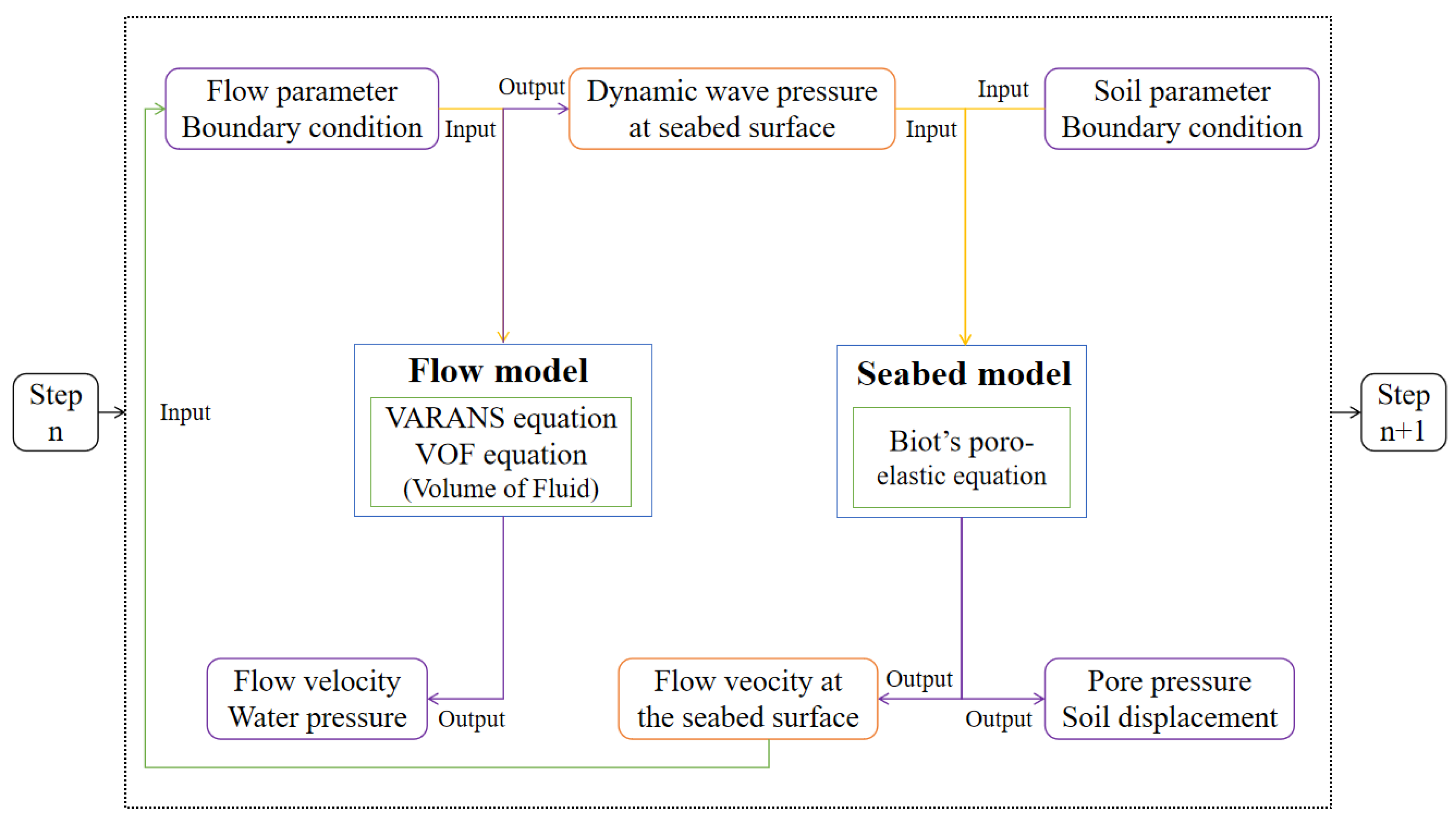
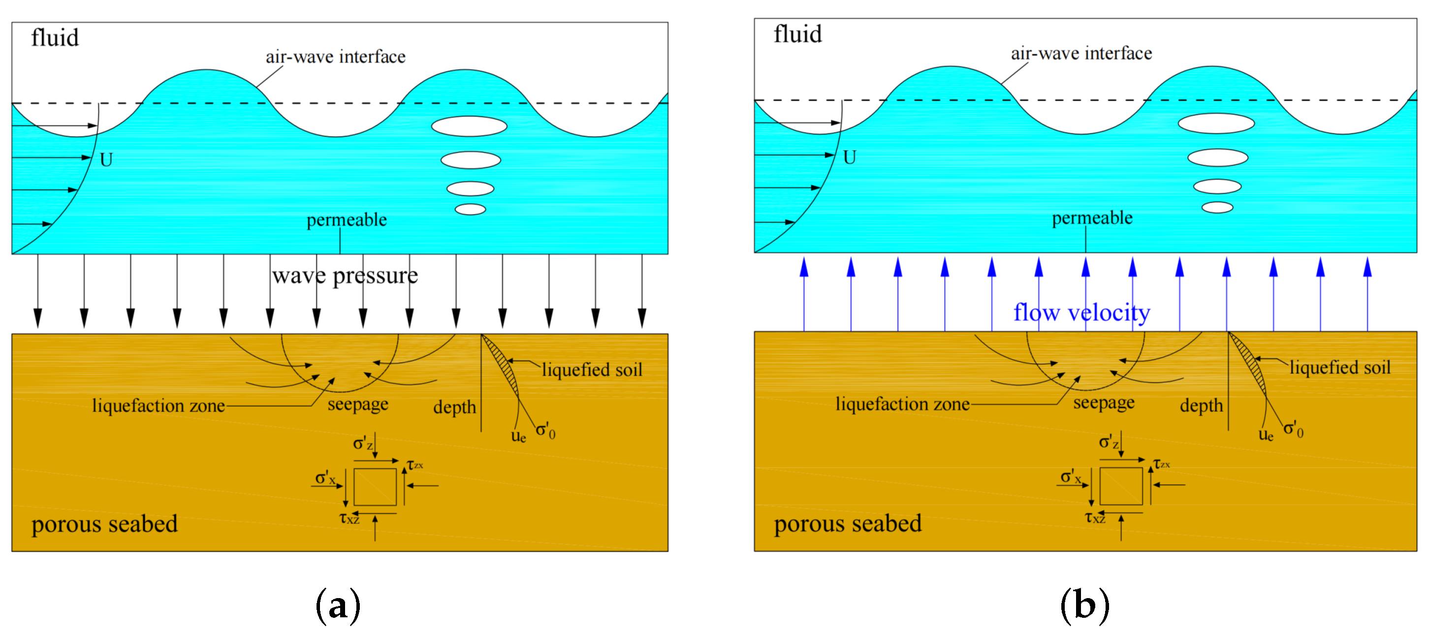
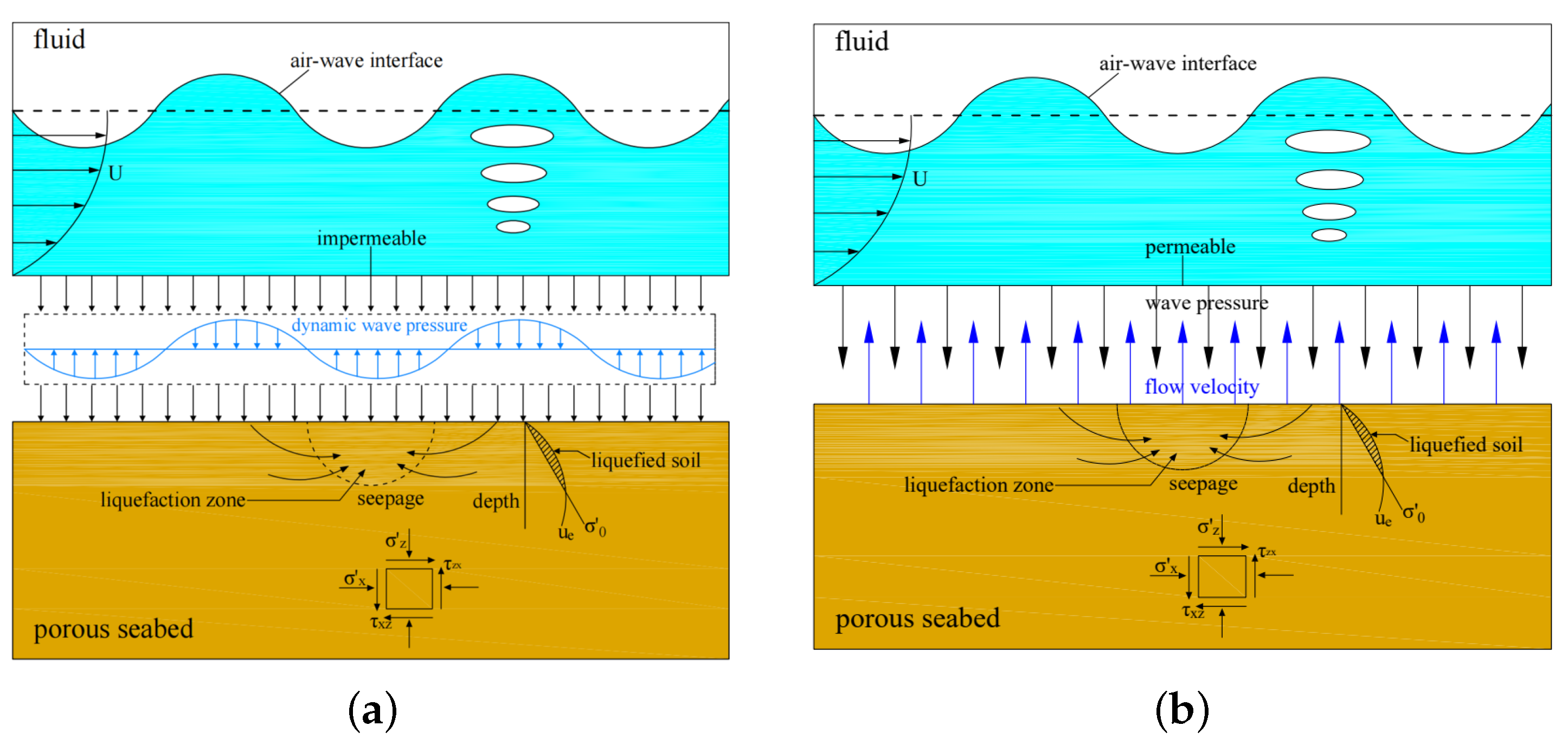
- Steps 1: The VARANS equations, as shown in shown in (1)–(3), and the VOF equation, as shown in (4), are solved by the input wave parameters and boundary conditions. Then the flow velocity and water pressure in the whole computational domain are obtained. When the entire flow field stabilizes after a certain number of iterations, the dynamic wave pressure at the bottom of the fluid is extracted and transmitted as a boundary condition to the seabed surface. In the first cycle, assuming the flow velocity at the bottom of the fluid domain is zero, a one-way coupling algorithm is used. After the second wave cycle, the boundary condition at the seabed surface will be the updated velocity obtained from the seabed model, i.e., from Step 3. The coupling process shown in Figure 4a is illustrated.
- Steps 3: The flow velocities at the interface of the fluid and seabed are calculated by the pore pressure and soil displacements in the seabed, as shown in (5), and transported to the fluid bottom. The flow velocities at the fluid bottom are updated, as shown in Figure 4b. Then, the flow field will be modeled with the new boundary condition at , and the effects of the seabed characteristics will be integrated into the flow model.
- Steps 4: To date, a complete wave–seabed two-way coupling process has been finished. We then proceed to the next time step and repeat steps 1–3.
2.4. Mesh Convergence and Stability of the Numerical Model
3. Model Validation
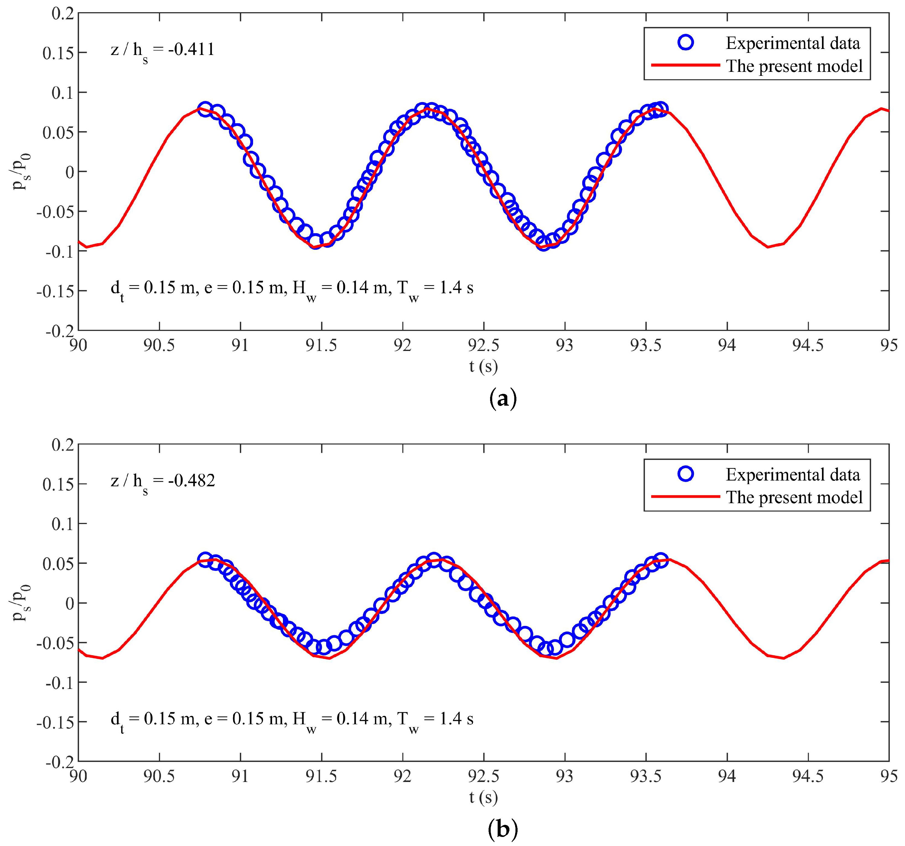
- Validation no. 1: Comparison of the experimental results between the present model and Sun et al. [29] for a single pipe with a trench layer; in this experiment, only the pore pressures along the pipe surface were measured.
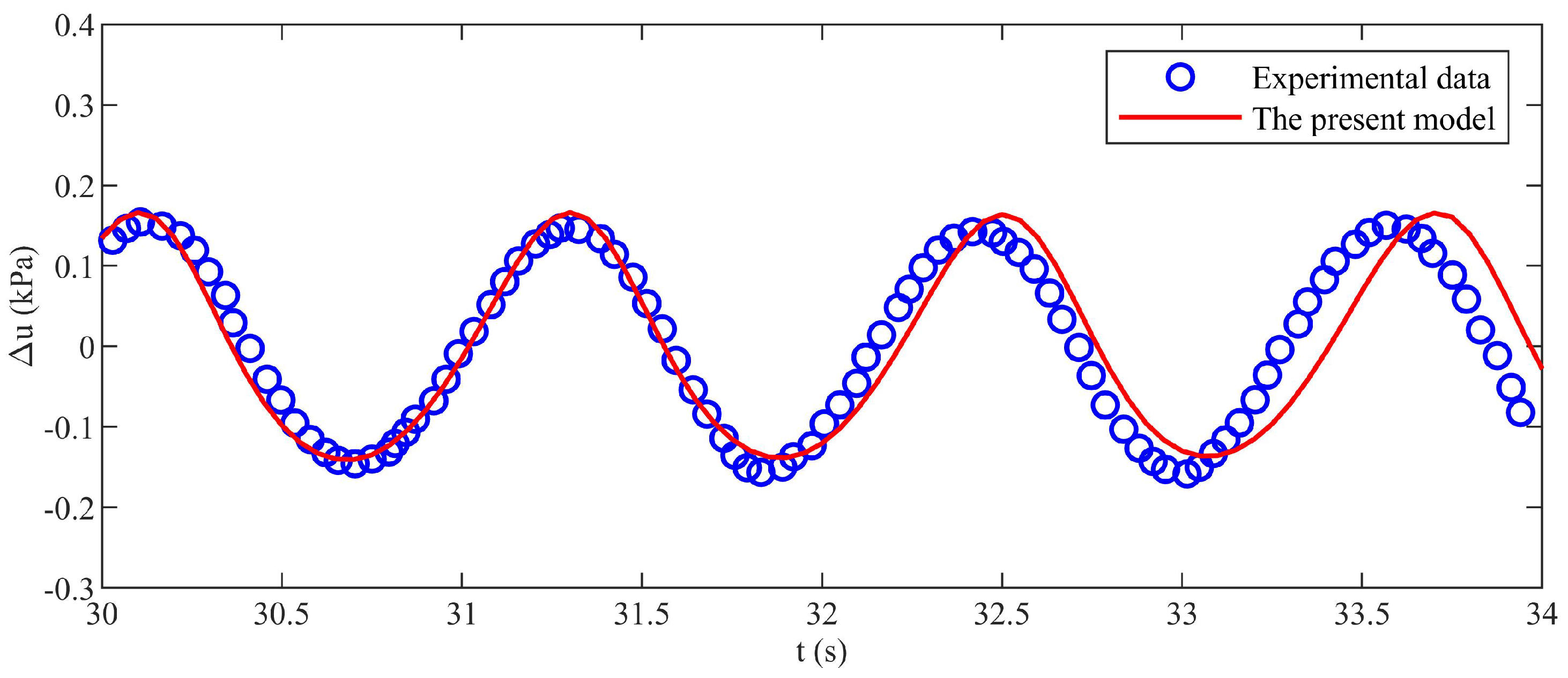
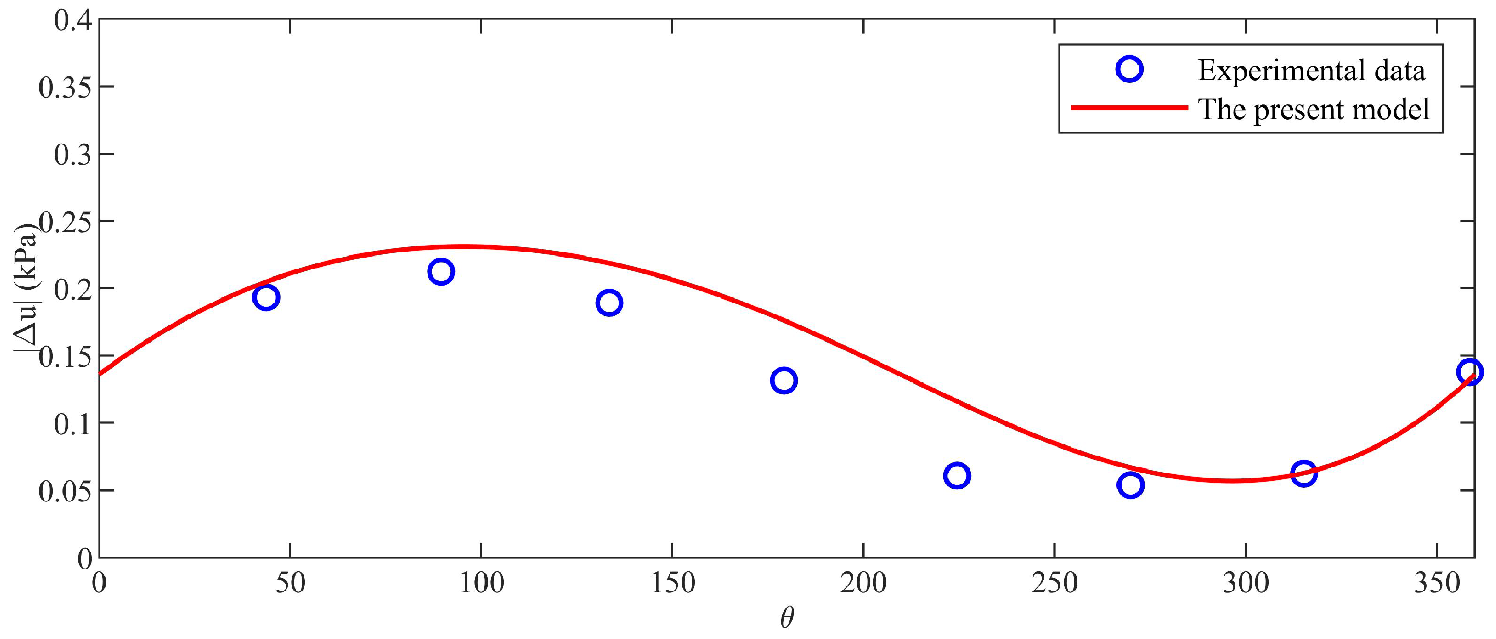
- Validation no. 2: Comparison of the experimental results between the present model and Zhai et al. [18] for twin pipes in tandem.
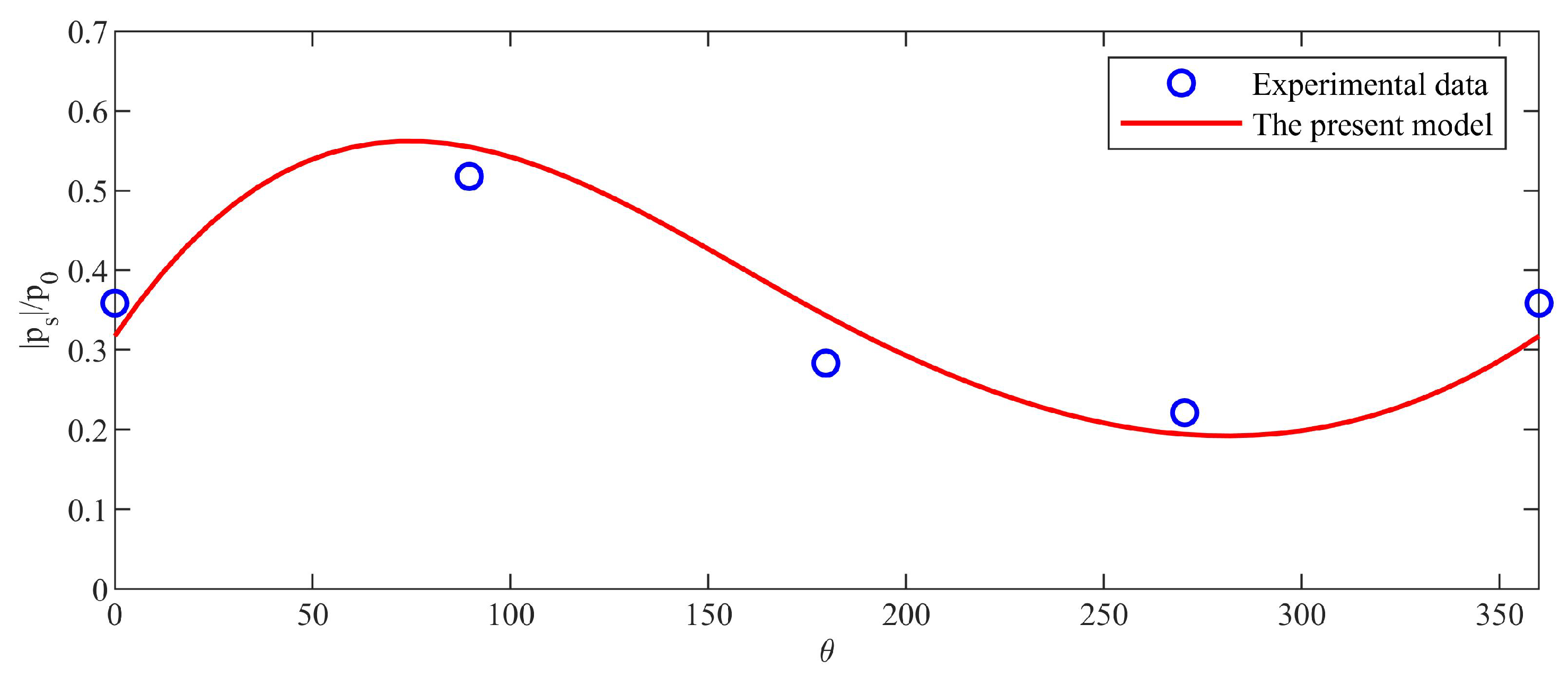
- Validation no. 3: Comparison of the experimental results between the present model and Chen et al. [30] for a single pipe with a trench layer; in this experiment, in addition to the pore pressures along the pipeline surface, additional measurements of pore pressures below the pipeline were taken.
| (m) | (m) | (s) | (m/s) | D (m) | ||
|---|---|---|---|---|---|---|
| Sun et al. [29] | ||||||
| 0.14 | 0.4 | 1.4 | 0.32 | 3.56 × 10 | 0.396 | 0.1 |
| Zhai et al. [18] | ||||||
| 0.1 | 0.4 | 1.2 | 0.3 | 3.56 × 10 | 0.369 | 0.1 |
| Chen et al. [30] | ||||||
| 0.08 | 0.4 | 1.2 | 0.3 | 3.57 × 10 | 0.369 | 0.08 |
3.1. Validation No. 1: A Single Pipeline in the Trench Layer

3.2. Validation No. 2: Twin Pipelines In Tandem
3.3. Validation No. 3: A Single Pipeline in the Trench Layer

4. Results and Discussion
4.1. Effect of Pipeline Configuration (Single Pipeline and Twin Pipelines)
4.2. Effect of Steady Current
4.3. Effects of Wave and Seabed Characteristics


4.4. Liquefaction Assessment around Fully Buried Pipelines
4.4.1. Seabed Consolidation
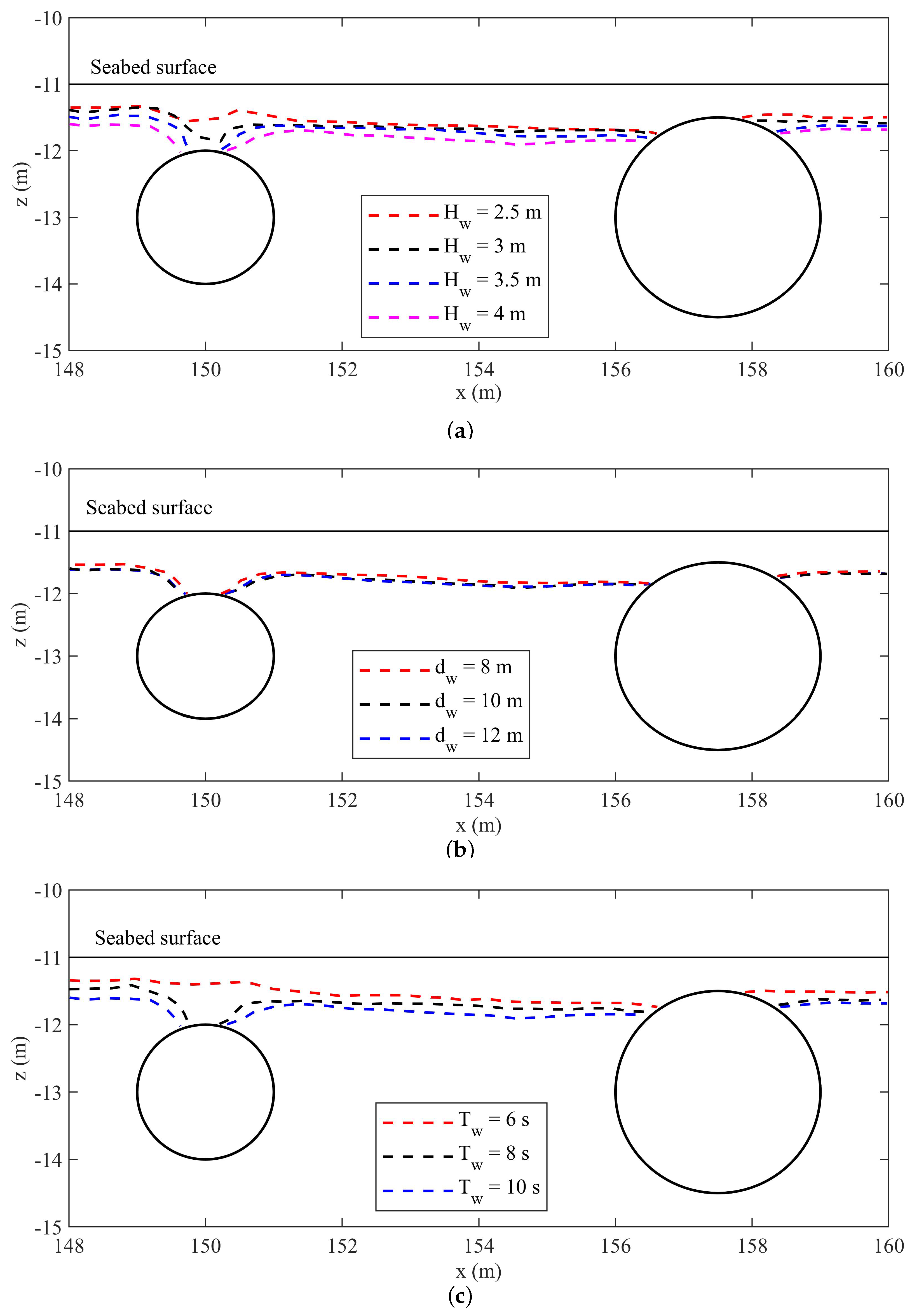
4.4.2. Distribution of Liquefaction Zones under Various Conditions
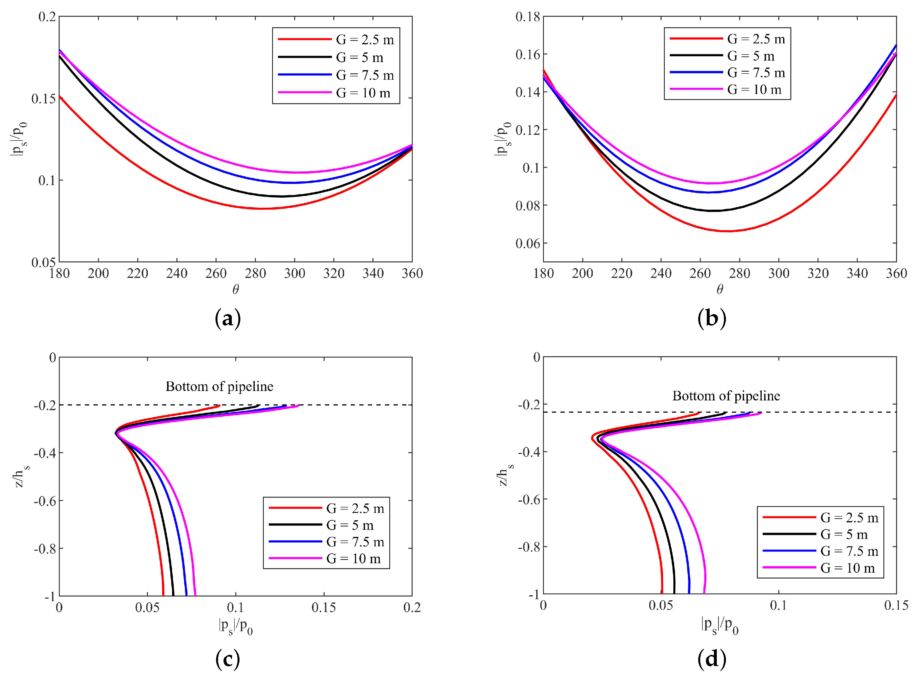
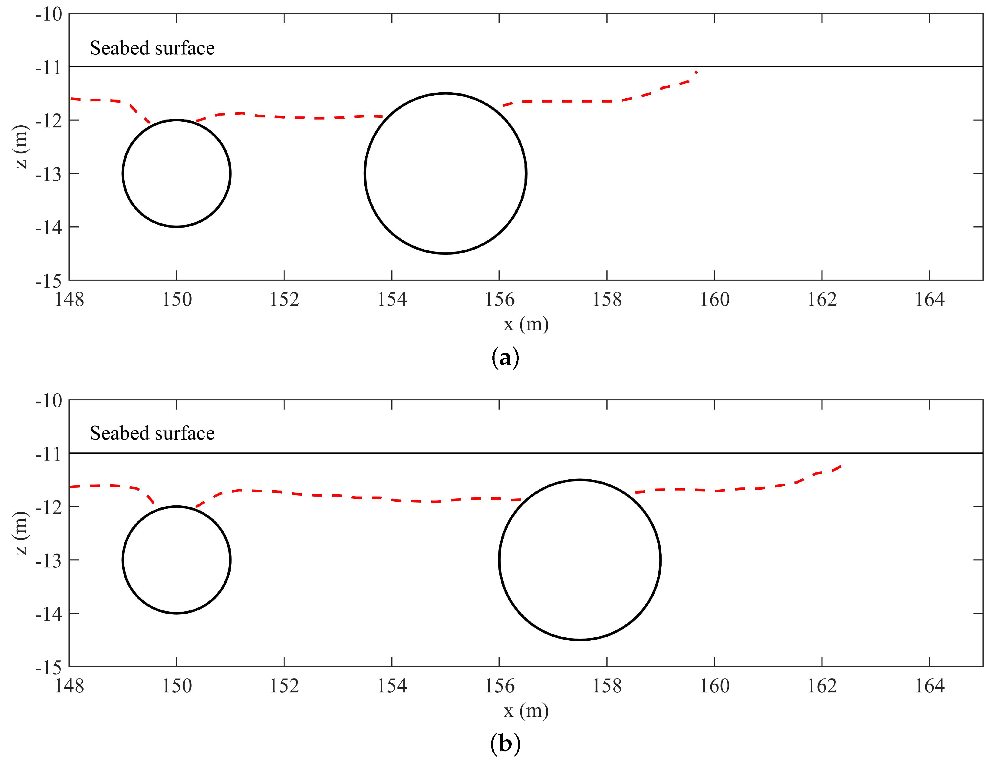
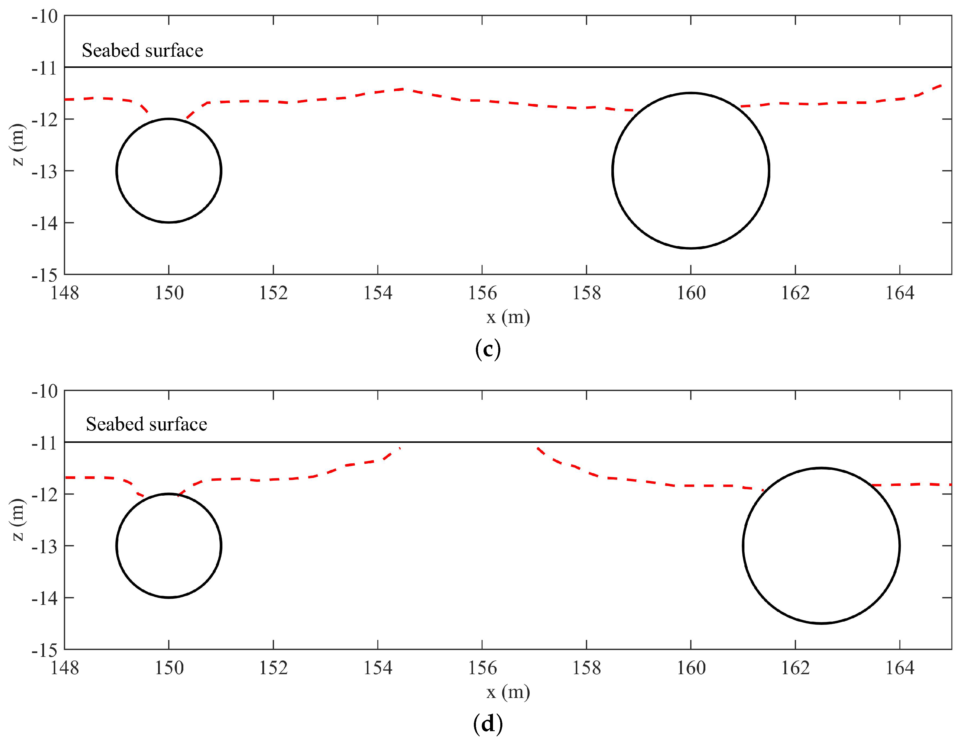
4.4.3. Effect of Pipeline Configuration
5. Conclusions
- This model adopts a two-way coupling algorithm to study the seabed response around pipelines. Experimental verification shows that the model is effective.
- The liquefaction range is greatly influenced by and . The results prove that when and are small, liquefaction hardly occurs.
- The soil characteristics greatly affect the seabed response and liquefaction zone distribution around the pipeline. This study mainly explores the effects of and . The liquefaction hardly occurs when and are large enough.
- The pipeline configurations, including the gap and pipeline radius ratio , also have obvious effects on the liquefaction zone around the twin pipelines. The liquefaction range around the pipeline gradually increases with the gap . However, the liquefaction range of the upstream and downstream pipelines is independent and similar to that of a single pipeline when G > 7.5 m.
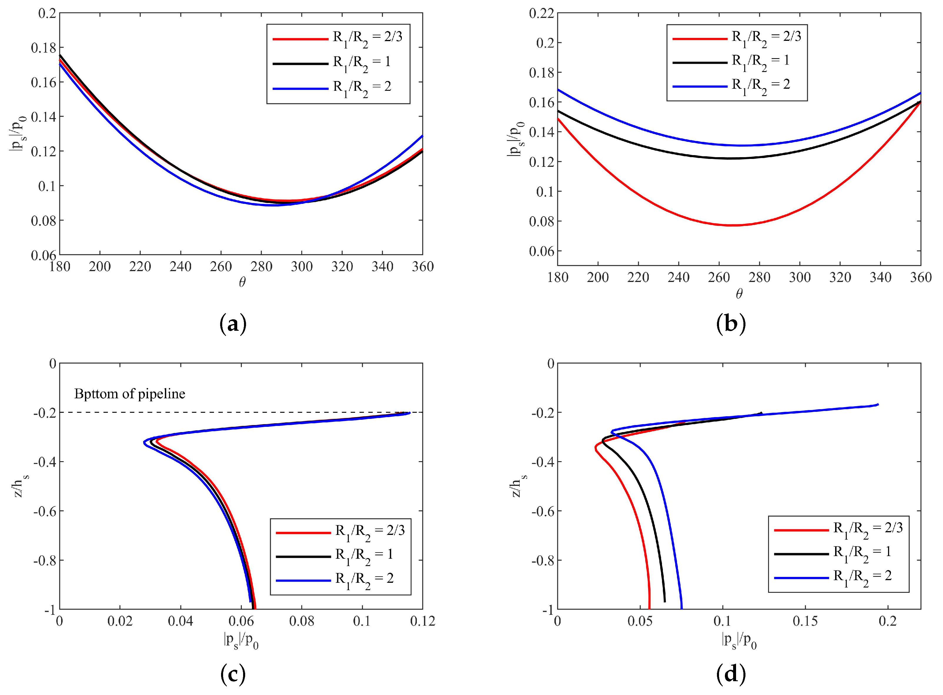
- As the pipeline radius ratio gradually increases, the liquefaction range above the downstream pipeline gradually decreases, and no liquefaction occurs below the pipeline, so the pipeline is relatively stable.
Author Contributions
Funding
Institutional Review Board Statement
Informed Consent Statement
Data Availability Statement
Acknowledgments
Conflicts of Interest
Notation
| Young’s module | |
| G | gap between pipes |
| shear modules | |
| wave height | |
| true bulk modulus of water | |
| absolute pressure | |
| pipeline radius | |
| pipeline radius | |
| pipeline radius ratio | |
| degree of saturation | |
| wave period | |
| velocity vector | |
| current velocity | |
| water depth | |
| burial depth | |
| burial depth | |
| g | gravitational acceleration |
| seabed thickness | |
| permeability | |
| porosity | |
| fluid pressure | |
| hydrodynamic pressure acting on the seabed surface | |
| t | Time |
| relative velocity field | |
| compressibility of pore fluid | |
| unit weight of water | |
| soil displacement vector | |
| Poisson’s ration | |
| initial stresses | |
| viscous stress vector |
References
- Sumer, B.M. Liquefaction around Marine Structures; World Scientific: Hackensack, NJ, USA, 2014. [Google Scholar] [CrossRef]
- Lin, Z.; Guo, Y.; Jeng, D.S.; Liao, C.; Rey, N. An integrated numerical model for wave–soil–pipeline interactions. Coast. Eng. 2016, 108, 25–35. [Google Scholar] [CrossRef]
- Duan, L.; Liao, C.; Jeng, D.S.; Chen, L. 2D numerical study of wave and current-induced oscillatory non-cohesive soil liquefaction around a partially buried pipeline in a trench. Ocean Eng. 2017, 135, 39–51. [Google Scholar] [CrossRef]
- Liang, Z.; Jeng, D.S.; Liu, J. Combined wave–current induced seabed liquefaction around buried pipelines: Design of a trench layer. Ocean Eng. 2020, 212, 107764. [Google Scholar] [CrossRef]
- Afzal, M.S.; Holmedal, L.E.; Myrhaug, D. Sediment transport in combined wave–current seabed boundary layers due to streaming. J. Hydraul. Eng. 2021, 147, 04021007. [Google Scholar] [CrossRef]
- Afzal, M.S.; Holmedal, L.E.; Myrhaug, D. Effect of Wave Skewness and Sediment Particle Size on Sediment Transport Due to Combined Wave–Current Seabed Boundary Layer Streaming. J. Hydraul. Eng. 2022, 148, 06022011. [Google Scholar] [CrossRef]
- Dutta, D.; Bihs, H.; Afzal, M.S. Computational Fluid Dynamics modelling of hydrodynamic characteristics of oscillatory flow past a square cylinder using the level set method. Ocean Eng. 2022, 253, 111211. [Google Scholar] [CrossRef]
- Dutta, D.; Afzal, M.S.; Alhaddad, S. 3D CFD study of scour in combined wave–current flows around rectangular piles with varying aspect ratios. Water 2023, 15, 1541. [Google Scholar] [CrossRef]
- Jeng, D.S. Porous Models for Wave-Seabed Interaction; Springer: Berlin/Heidelberg, Germany, 2012. [Google Scholar] [CrossRef]
- Yamamoto, T.; Koning, H.; Sellmeijer, H.; Hijum, E.V. On the response of a poro-elastic bed to water waves. J. Fluid Mech. 1978, 87, 193–206. [Google Scholar] [CrossRef]
- Hsu, J.R.C.; Jeng, D.S. Wave-induced soil response in an unsaturated anisotropic seabed of finite thickness. Int. J. Numer. Anal. Methods Geomech. 1994, 18, 785–807. [Google Scholar] [CrossRef]
- Seed, H.B.; Rahman, M.S. Wave-induced pore pressure in relation to ocean floor stability of cohesionless soils. Mar. Geotechnol. 1978, 3, 123–150. [Google Scholar] [CrossRef]
- Sumer, B.M.; Fredsøe, J. The Mechanics of Scour in the Marine Environment; World Scientific: Hackensack, NJ, USA, 2002. [Google Scholar] [CrossRef]
- Rados, K.; Pitt, D.; Macfarlane, D.; Dimla, D. On the interaction of pipelines on the seabed. In Proceedings of the Tenth International Offshore and Polar Engineering Conference, Seattle, WA, USA, 28 May–2 June 2000; pp. 155–161. [Google Scholar]
- Zhao, M.; Cheng, L. Numerical modeling of local scour below a piggyback pipeline in currents. J. Hydraul. Eng. ASCE 2008, 134, 1452–1463. [Google Scholar] [CrossRef]
- Jo, C.H.; Shin, Y.S.; Min, K.H. Numerical and Experimental Studies of Dual Subsea Pipelines in Trench. J. Ship Ocean Technol. 2002, 6, 12–22. [Google Scholar]
- Zhang, J.; Zheng, J.; Zhang, C.; Jeng, D.S.; Guo, Y. Numerical study on the interaction between waves and twin pipelines in sandy seabed. J. Coast. Res. 2013, 65, 428–433. [Google Scholar] [CrossRef]
- Zhai, Y.; Zhang, J.; Guo, Y.; Tang, Z.; Zhang, T. Study of wave-induced seabed response around twin pipelines in sandy seabed through laboratory experiments and numerical simulations. Ocean Eng. 2022, 244, 110344. [Google Scholar] [CrossRef]
- Chen, X.; Jeng, D.S.; Liang, Z.D. Numerical analysis of seabed liquefaction in the vicinity of two tandem pipelines in a trench. Ocean Eng. 2022, 266, 112656. [Google Scholar] [CrossRef]
- Gao, Y.; Lin, J.; Zhang, J.; Guo, Y. Numerical modeling of combined wave and current-induced residual liquefaction around twin pipelines. Ocean Eng. 2022, 261, 112134. [Google Scholar] [CrossRef]
- Zhai, H.; Jeng, D.S. Two-way coupling model for wave-induced oscillatory soil response in a porous seabed. Ocean Eng. 2022, 249, 110791. [Google Scholar] [CrossRef]
- Zhang, J.S.; Zhang, Y.; Jeng, D.S.; Liu, P.F.; Zhang, C. Numerical simulation of wave–current interaction using a RANS solver. Ocean Eng. 2014, 75, 157–164. [Google Scholar] [CrossRef]
- Higuera, P.; Lara, J.L.; Losada, I.J. Realistic wave generation and active wave absorption for Navier-Stokes models: Application to OpenFOAM. Coast. Eng. 2013, 71, 102–118. [Google Scholar] [CrossRef]
- Liang, Z.D.; Jeng, D.S. PORO–FSSI–FOAM model for seafloor liquefaction around a pipeline under combined random wave and current loading. Appl. Ocean Res. 2021, 107, 102497. [Google Scholar] [CrossRef]
- Jeng, D.S.; Cha, D. Effects of dynamic soil behavior and wave non-linearity on the wave-induced pore pressure and effective stresses in porous seabed. Ocean Eng. 2003, 30, 2065–2089. [Google Scholar] [CrossRef]
- Ulker, M.B.C.; Rahman, M.S.; Jeng, D.S. Wave-induced response of seabed: Various formulations and their applicability. Appl. Ocean Res. 2009, 31, 12–24. [Google Scholar] [CrossRef]
- Ye, J.H.; Jeng, D.S. Response of Porous Seabed to Nature Loadings: Waves and Currents. J. Eng. Mech. 2011, 138, 601–613. [Google Scholar] [CrossRef]
- Karunarthna, K.; Lin, P. Numerical simulation of wave damping over porous seabeds. Coast. Eng. 2006, 53, 845–855. [Google Scholar] [CrossRef]
- Sun, K.; Zhang, J.; Gao, Y.; Jeng, D.S.; Guo, Y.; Liang, Z. Laboratory experimental study of ocean waves propagating over a partially buried pipeline in a trench layer. Ocean Eng. 2019, 173, 617–627. [Google Scholar] [CrossRef]
- Chen, H.; Zhang, J.; Tong, L.; Sun, K.; Guo, Y.; Wei, C. Experimental study of soil responses around a pipeline in a sandy seabed under wave-current load. Appl. Ocean. Res. 2023, 130, 103409. [Google Scholar] [CrossRef]
- Zhang, Y.; Jeng, D.S.; Gao, F.; Zhang, J.S. An analytical solution for response of a porous seabed to combined wave and current loading. Ocean Eng. 2013, 57, 240–247. [Google Scholar] [CrossRef]
- Zhao, H.Y.; Jeng, D.S.; Guo, Z.; Zhang, J.S. Two-dimensional model for pore pressure accumulations in the vicinity of a buried pipeline. J. Offshore Mech. Arct. Eng. ASME 2014, 136, 042001. [Google Scholar] [CrossRef]




| Characteristics | Value | Unit |
|---|---|---|
| Wave characteristics | ||
| 0 or various | [m/s] | |
| 4.0 or various | [m] | |
| 10.0 or various | [m] | |
| 8.0 or various | [s] | |
| Seabed characteristics | ||
| 1 × 10 or various | [m/s] | |
| 0.3 | - | |
| 0.425 | - | |
| 0.98 or various | - | |
| 1 × 10 | [N/m] | |
| 2.6 × 10 | [N/m] | |
| 15 | [m] | |
| Pipeline characteristics | ||
| 1 | [m] | |
| 0.5–1.5 | [m] | |
| 2 | [m] | |
| 2.5 or various | [m] | |
| G | 5 or various | [m] |
Disclaimer/Publisher’s Note: The statements, opinions and data contained in all publications are solely those of the individual author(s) and contributor(s) and not of MDPI and/or the editor(s). MDPI and/or the editor(s) disclaim responsibility for any injury to people or property resulting from any ideas, methods, instructions or products referred to in the content. |
© 2023 by the authors. Licensee MDPI, Basel, Switzerland. This article is an open access article distributed under the terms and conditions of the Creative Commons Attribution (CC BY) license (https://creativecommons.org/licenses/by/4.0/).
Share and Cite
Zhang, J.; Cui, L.; Zhai, H.; Jeng, D.-S. Assessment of Wave–Current-Induced Liquefaction under Twin Pipelines Using the Coupling Model. J. Mar. Sci. Eng. 2023, 11, 1372. https://doi.org/10.3390/jmse11071372
Zhang J, Cui L, Zhai H, Jeng D-S. Assessment of Wave–Current-Induced Liquefaction under Twin Pipelines Using the Coupling Model. Journal of Marine Science and Engineering. 2023; 11(7):1372. https://doi.org/10.3390/jmse11071372
Chicago/Turabian StyleZhang, Jiayi, Lin Cui, Hualing Zhai, and Dong-Sheng Jeng. 2023. "Assessment of Wave–Current-Induced Liquefaction under Twin Pipelines Using the Coupling Model" Journal of Marine Science and Engineering 11, no. 7: 1372. https://doi.org/10.3390/jmse11071372
APA StyleZhang, J., Cui, L., Zhai, H., & Jeng, D.-S. (2023). Assessment of Wave–Current-Induced Liquefaction under Twin Pipelines Using the Coupling Model. Journal of Marine Science and Engineering, 11(7), 1372. https://doi.org/10.3390/jmse11071372


