Abstract
In this paper, we propose a trajectory tracking controller with experimental verification for torpedo-like autonomous underwater vehicles (AUVs) with underactuation characteristics. The proposed controller overcomes the underactuation problem by designing the desired error dynamics in a coupled form using state variables in body-fixed and world coordinates. Unlike the back-stepping control requiring high-order derivatives of state variables, the proposed controller only requires the first derivatives of the states, which can alleviate noise magnification issues due to differentiation. We adopt time delay estimation to estimate the dynamics indirectly using control inputs and vehicle outputs, making the proposed controller relatively easy to apply without requiring the all of the vehicle dynamics. We also address some practical issues that commonly arise in experimental environments: handling measurement noises and actuation limits. To mitigate the effects of noise on the controller, a filtering technique using a moving window average is employed. Additionally, to account for the actuation limits, we design an anti-windup structure that takes into consideration the nonlinearity between the thrusting force and rotating speed of the thruster. We verify the tracking performance of the proposed controller through experimentation using an AUV. The experimental results show that the 3D motion control of the proposed controller exhibits an RMS error of 0.3216 m and demonstrate that the proposed controller achieves accurate tracking performance, making it suitable for survey missions that require tracking errors of less than one meter.
1. Introduction
Designing a trajectory tracking controller for torpedo-like autonomous underwater vehicles (AUVs) is challenging due to their underactuation characteristics. These vehicles have only three control inputs—surge force, pitch, and yaw moment—to control their 3D motion in space. The lack of control inputs leads to dissatisfaction of the matching condition, where certain uncertain terms in the state equation cannot be directly compensated for by the control inputs [1,2]. Additionally, the vehicles have nonlinear dynamics involving both rigid body dynamics and hydrodynamics [2]. In the development of AUVs and their control systems, it is crucial to verify their performance in experimental environments. During such verification, numerous issues can affect the system’s performance, including sensor measurement noise, modeling errors in system dynamics, disturbances, and imperfections in control systems, such as jitter in the sampling time. As a result, developing a trajectory tracking controller for AUVs is challenging in two aspects: the design of the control algorithm and the experimental verification process.
Regarding the controller design manner, there have been several research works to propose trajectory tracking control scheme for AUVs. To overcome the matching condition issues of the vehicles, several research works have proposed control schemes based on back-stepping control (BC). BC using the vehicle dynamic model was proposed in [3,4,5,6]. BC with time delay estimation (BCTDE), an indirect estimator of the vehicle dynamics, has also been studied [2,7,8]. BC provides an excellent and systematic method to handle matching condition issues. However, it requires high-order derivatives of the state variables, which may result in instability in experimental environments due to the magnification of noise effects. There have been several studies on controlling the vehicles using other schemes. Hierarchical design of the controllers has been researched to address the underactuation characteristics [9,10]. Sliding mode control has been applied to gain robustness against model errors and disturbances [11,12,13,14]. Adaptive schemes have been employed to resolve model uncertainty [15,16]. Neural networks have been used for robust path following [17,18].
Regarding the experimental verification manner, however, it is hard to find previous research works proposing trajectory tracking algorithms with experimental results. For example, the aforementioned previous research works primarily demonstrate control performance with simulation results and lack experimental verification. The reasons for the absence of experiments in previous works are not explicitly mentioned, but this could be attributed to the need for further investigation to address practical issues such as sensor noises or modeling errors in AUV dynamics, including disturbances. For example, the authors have attempted to verify the performance of the BCTDE [2,7,8] and found it difficult to determine stable gains for the BCTDE. Figure 1 illustrates the experimental results for depth control using the BCTDE, which indicate unstable responses. This instability arises because the BCTDE requires high-order differentiation of the state variables to handle unmatched dynamics and disturbances, thereby amplifying the effects of noise in the state measurements. As another reason for the lack of experimentation, the difficulty of obtaining a suitable experimental platform can be considered, as AUVs are costly plaforms. In constrast to the trajectory tracking problem, however, there have been several research works that proposed via point tracking control of underactuated AUVs with experimental verification [19,20,21]. These research works utilize traditional approaches employing PID-type controllers for the forward velocity, pitch angle (or depth), and heading angle, combined with a desired heading angle planner such as the line of sight (LOS) [22,23,24]. Designing via point tracking controllers is relatively straightforward since each controller focuses only on stabilizing states with dynamics matched to the control inputs. However, they mainly focus on waypoint tracking and are unable to handle time-varying trajectory tracking problems. There have also been research works suggesting trajectory tracking controllers for underwater vehicles with full degree-of-freedom (DOF) actuation [25,26,27,28,29]. In such cases, the vehicle can generate the control actuations for every controlled state, eliminating issues arising from a lack of satisfaction of the matching condition.
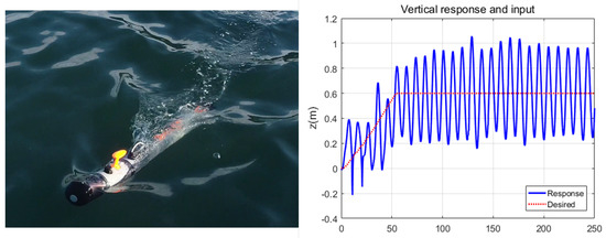
Figure 1.
Experimental results for depth control using the BCTDE. The results indicate an almost unstable response due to the high–order differentiation of states required by the controller, which amplifies the noise effect in the state measurements.
In this paper, we propose a robust trajectory tracking controller for the 3D motion of underwater vehicles, along with experimental verification of its control performance. In terms of controller design, the proposed controller incorporates an appropriate design of the desired error dynamics and time delay estimation (TDE). To address the underactuation issues of the vehicle, the desired error dynamics is formulated in a coupled form between the state variables in body-fixed and world coordinates. By utilizing the TDE [2,30], the controller effectively compensates for the nonlinear dynamics and disturbances of the vehicle while maintaining a simple structure. The proposed controller only requires the state variables and their first derivatives, mitigating the issues of noise amplification due to differentiation. An initial version of the proposed controller was presented in [31], and in this paper, we extend the controller for motion control in a 3D space. In terms of experimental implementation, practical issues related to measurement noise and actuation limitations are addressed. A moving average filter is employed to mitigate the effects of sensor noise on control performance, and actuation limitations combined with nonlinear dynamics are also considered. We verify the tracking performance of the proposed controller through experiments conducted on an AUV.
2. Controller Design for the AUV
2.1. AUV Systems and Motion-Governing Equations
Figure 2 illustrates the AUV platform utilized in this research, which was developed by Hanwha Systems [32]. The AUV serves as a testbed for underwater docking tasks [33]. The linear velocities of the vehicle are measured using a Doppler velocity log (DVL), and the angular velocities are measured using an inertial measurement unit (IMU). The position of the vehicle in the world coordinate is estimated using an extended Kalman filter (EKF) that utilizes navigation sensor data from an IMU, a DVL, a depth sensor, a digital compass, and a global navigation satellite system (GNSS) [34,35,36]. The vehicle is equipped with a thruster for forward propulsion, as well as rudder fins and stern fins for lateral and vertical moments, respectively. The actuators are controlled by an ARM-based embedded system with a control sampling frequency of 10 Hz.
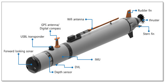
Figure 2.
AUV used in the experiment. The vehicle was developed by Hanwha Systems [32]. The AUV serves as a testbed for underwater docking tasks [33].
To formulate the motion-governing equation, let us consider the control problem of the vehicle in a 3D space as shown in Figure 3. Assuming that the roll motion of the vehicle can be neglected, the governing equations for motion are given as follows [8,37]:
where and denote and , respectively; ; ; x, y, z, , and are the positions and orientations of the vehicle in the world coordinate; u, v, w, q, and r are the translational velocities and angular velocities; , , and are the control inputs; , , , , , and are the bounded external disturbances, such as ocean currents and waves; represent the terms for the combined mass and intertia parameters; ; ; W is the gravity, B is the buoyancy of the vehicle; represents the hydrodynamic damping and friction terms; and is the rotation matrix of with respect to . From Equation (2), the dynamics of the controllable states are rearranged as follows:
where , , and are the positive constants which represent the known ranges of inertia and , , and are nonlinear terms, defined as
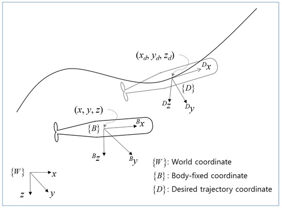
Figure 3.
Definition of coordinates.
2.2. Desired Trajectory
Due to the underactuated nature, only three trajectory variables can be designed independently. Note that in Equation (2), there are only three independent control inputs to control five DOFs in the world coordinate. We can set the independent trajectory variables as x, y, and z in . The trajectories can be represented by the following continuous time functions [8]:
2.3. Dynamics of Tracking Error
In this subsection, we arrange the tracking error dynamics of the vehicle by describing them in the desired trajectory coordinate . This approach helps to minimize changes in the relationship between variables in different coordinates [38,39]. When there is no tracking error, u affects for every attitude of the vehicle, and the transformation can be easily achieved as follows [40]:
where denotes the translational position of the vehicle with respect to and . Using Equation (7), the desired trajectories in Equation (5) can be transformed into those in as follows:
Subtracting Equation (7) from Equaiton (8) yields the following relationship:
where . Note that from Equation (9), the tracking problem in is identical to that in . Convergence of the tracking error in guarantees convergence in . This is because is a rotation matrix and cannot be singular. By taking the derivatives of Equation (9) with Equations (1) and (5) and introducing positive constants , , and , the error dynamics of the state variable in can be rearranged as follows [8]:
Refer to [8] for a detailed derivation of Equation (10). The last term in the above equation represents the nonlinear terms defined as follows:
where and is a skew-symmetric matrix of [8]. Aside from that, from Equations (1) and (6), the attitude error is obtained as follows:
where is a positive constant and
2.4. Controller Design Using the Coupled Error Dynamics and Time Delay Estimation
In this paper, our goal is to design the desired error dynamics for , , and that can asymptotically stabilize the tracking errors of , , and , respectively. Note that from Equation (3), one can directly control the variables in , namely u, q, and r, by designing appropriate control inputs , , and , respectively. From Equations (10) and (12), u adjusts , q affects and consequently , and r determines and therefore . Thus, coupled error dynamics between the variables in and can be designed to stabilize the variables in . The desired error dynamics of , , and are designed as follows:
where represents the control gains.
In the manner of the computed torque control, the controller for Equation (3) can be designed as follows:
where denotes the estimate of • and , , and are the command inputs to insert the desired dynamics for u, q, and r, respectively. When , the controlled dynamics is obtained from Equations (3) and (15) as follows:
To induce the desired error dynamics in Equations (14)–(16), the command inputs are designed as follows:
To implement the controller in Equation (15), it is necessary to obtain , , and , the estimates of Equation (4). However, obtaining an exact dynamic model of Equation (4) is difficult and time-consuming. To address this, we employ the TDE [2,30,41,42] for robust and efficient estimation. The key idea behind TDE is that if the system dynamics are given as a continuous or piece-wise continuous function, then the variation in the dynamics during a very short time can be negligible. Thus, the value of the dynamics at the current time can be estimated by using the value of the dynamics at a short time before. Based on this idea, the system dynamics can be estimated indirectly by utilizing previous information on the system input and output. From Equation (3), the dynamics can be estimated as follows:
where L denotes a short time delay which is commonly set as the sampling time of the control system. As a result, the final form of the proposed controller is Equation (15) with Equations (17) and (18).
It is noteworthy that the proposed controller in Equation (15) with Equations (17) and (18) only requires the first derivative of the state variables and the states themselves. The linear and angular velocities can be measured using IMU and DVL, while the vehicle’s position can be obtained through a navigation algorithm such as a Kalman filter, utilizing sensors such as IMU, DVL, the depth sensor, and the digital compass [34]. The advantage of not requiring high-order differentiation of the states is that it helps stabilize the controller in experimental environments. This is because differentiating the states amplifies the noise effect present in the state measurements. In comparison, the BCTDE [2,7,8] necessitates third-order differentiation of the states. Therefore, one can expect that the proposed controller is relatively easier to stabilize in experimental environments. In addition, note that the TDE method does not require the entire vehicle dynamics model. One can design the proposed controller by only selecting the inertial gains, such as , , , , , , and , as well as the feedback gains, such as , , , , , , , and .
2.5. Error Dynamics of the Proposed Controller
The TDE provides an efficient way to estimate the nonlinear dynamics of the vehicle, but it cannot estimate the dynamics variation exactly during a sampling time L. Thus, an estimation error of the dynamics remains. Taking into account the estimation error of the TDE, one can rearrange the error dynamics in Equaiton (14) by utilizing Equations (3) and (15) with Equations (17) and (18) as follows:
where denotes the TDE errors, which are defined as follows:
From Equations (10), (12), and (19), the error dynamics of the controlled system for the forward, lateral, and vertical directions, respectively, are as follows:
By taking the Laplace transform of Equations (21a)–(21c), one can examine the stability of the error dynamics and the influence of the forcing functions , , and . The Laplace-transformed error dynamics can be obtained as follows:
where s denotes the Laplace operator and
From Equations (22a)–(22c), the influence of each term of the forcing functions , , and can be estimated. The tracking errors in a steady state can be analyzed by using the final value theorem of the Laplace transform: . For example, from Equations (22a) and (23a), . Assume that is given as a step function: with a constant l. Then, , and one can estimate that in the forward direction error, , there will be a steady state error dependent on the amount of disturbed dynamics l and the control gains , , and . The controller cannot perfectly compensate for the influence of the forcing function, but it can attenuate the influence by selecting appropriate control gains.
The characteristic equations in Equations (23a)–(23c) are useful for selecting appropriate control gains. In order to ensure stable error dynamics, the characteristic equations must satisfy the Hurwitz condition, and the gains must be chosen accordingly. Additionally, the inertial gains , , , , , , and can be obtained through tuning. Previous research works utilizing the TDE have suggested selecting inertial gains within a known range of the vehicle’s inertial terms. If the vehicle model is unknown, however, then the inertial gains can be obtained through tuning [2,30].
3. Practical Issues for the Experiments
When setting up the controller for the experiment, practical issues such as the noise effects of the measurements and actuator limitations have to be considered. These issues will be discussed in the following subsections.
3.1. Handling the Noise Effect in the TDE
The TDE provides an effective and efficient method for estimating the nonlinear dynamics of vehicles. However, the use of state derivatives in the TDE amplifies the noise effect in the measurement of the state variables. In the case of underwater vehicles, the vehicle’s position is usually estimated by Kalman filtering of the sensor data, such as acceleration from the IMU and velocity from the DVL, which have considerable measurement noise. The amplification of noise can undermine the stability conditions. One way to handle this is to use the low-pass filtering effects of the inertial gains of the TDE [30]. Decreasing the inertial gains shows a similar effect to low-pass filtering. However, we found experimentally that adjusting the inertial gains was not enough. Therefore, we devised a method to attenuate the noise effect of the TDE. The idea is quite simple: cut down the direct TDE value and supplement the remaining part with the averaged value of the TDE. Figure 4 shows the noise attenuation method in the TDE. Note that the use of an average filter in Figure 4 can attenuate the noise effect because the filter also averages the noise. However, the filter may slightly degrade the performance of the TDE because the filtered value of the TDE cannot estimate exactly any quick changes in vehicle dynamics. In the case of underwater vehicles, dynamic changes occur due to the vehicle dynamics and disturbance changes such as sea currents, which depend on the mission (or desired trajectory) and the environment. In the case of AUVs, dynamic changes may not be fast because they are commonly used for surveys of large areas, and disturbances such as sea currents change slowly according to tide variation.
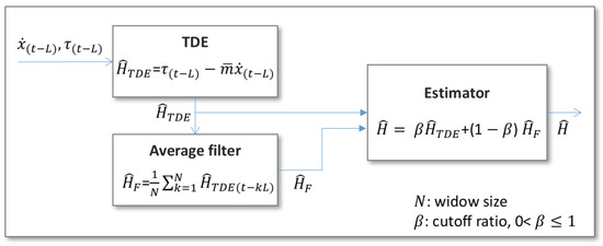
Figure 4.
Filtering the TDE to reduce the noise effect. The algorithm reduces the direct TDE value and supplements the remaining part with the averaged value of the TDE. This mitigates the noise present in the TDE thanks to the averaging effect.
3.2. Handling Nonlinearity and the Limits of the Actuators
When designing a controller, it is important to consider the actuator characteristics, such as nonlinearity and the actuation limits. For instance, the thruster of a vehicle exhibits nonlinear dynamics between the propulsion force and rotation speed of the thruster. Moreover, the thruster has limits on rotational velocity and acceleration because the thruster is a mechanical system. In this subsection, we address compensation methods for the actuator characteristics, focusing on the thrusters in particular and briefly touching on the rudder fins and stern fins. The thruster dynamics are as follows [23,43]:
where n denotes the rotation velocity of the thruster and and represent the actuator coefficients corresponding to the rotational speed of the actuator and fluid speed around the actuator, respectively. By ignoring and from Equation (24), we adopted a simple thruster model, which is as follows:
This is because the effect of , the term included in the RHS of Equation (24), can be compensated for by the feedback loop of the controller, and the scale coefficient in Equation (24) can be adjusted by tuning the controller gain. Note that when substituting Equation (24) into the first equation of Equation (3), can be treated as part of the nonlinear term (i.e., ). The coefficient simply scales the value of (i.e., ).
Regarding the actuation limit of the thrusting force, we considered the limits on the rotational velocity and acceleration of the thrusting propeller as follows:
where represents n with the actuation limit and is a limiting function that considers the limit of n and as well as the sign of n. Note that in Equation (26), the sign condition is included because only the forward thrusting force is available. In the case of the controllers using the TDE, handling the actuation limit to prevent the wind-up phenomenon is as straightforward as incorporating a limit block to ensure that the calculated control input for the TDE matches the actual value of the actuation applied to the vehicle [44]. Figure 5 shows the limiter block for handling the actuation limit of the thrusting force, while Figure 6 shows the structure of the limiter block, which is explained by Equation (26). In the case of the rudder fins and stern fins, one can handle the actuation limit in similar ways to the case of the thrusting force. The only differences are that (1) the actuation forces are linear with the fin motions [23] and (2) both positive and negative forces are available. By simply removing the condition in Equation (26) and eliminating the blocks of sqrt() and square() in Figure 5 and Figure 6, the same limiting algorithm can be applied to the rudder fins and the stern fins.
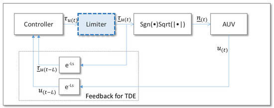
Figure 5.
TDE feedback block for of the controller. denotes a signum function, and . The ‘Limiter’ block is included to prevent the wind-up phenomenon due to the actuation limit [44]. The ‘’ block is for compensating for the actuation dynamics in Equation (25).

Figure 6.
Limiter block of the thrusting force : The thruster has actuation limits on the rotation speed and acceleration. Therefore, before checking the limitation, the ‘’ block is included to convert the control force into the rotation speed according to Equation (25).
4. Experimental Study
The tracking performance of the proposed controller was experimentally verified using the AUV platform depicted in Figure 2. The experiments were performed in the seawater at a port located in the South Sea of Korea. For the experiment, the control gains were set as follows. The inertial gains were set to , , , , , , and by tuning, and the feedback gains , , , , , , , and were selected for the desired error dynamics having poles at (double poles), (triple poles), and (triple poles). In this case, the characteristic equations in Equations (23a)–(23c) had poles at (double poles), , and , which were placed in the LHP. Regarding the noise-handling algorithm in Figure 4, the window size for the average filter was set at , and the values for , , and in Equation (18) were , , and , respectively.
4.1. Experimental Verification of the Noise-Handling Issue
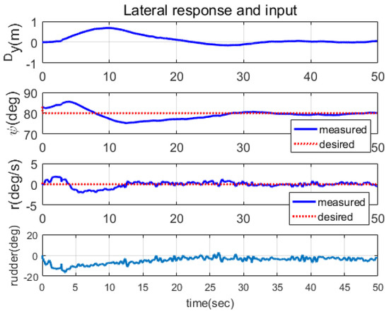
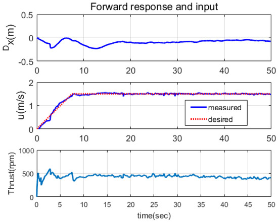
In this subsection, the noise handling method described in Section 3.1 is experimentally verified. The experiments were conducted on the surface of the sea, with actuations in the XY plane. The thrusters and rudder fins were activated, while the stern fins were deactivated. The tracking performances were compared between the case where the noise-handling algorithm was not applied and the case where the algorithm was applied. A trajectory involving linear motion was used, as shown in Figure 7. The experimental results are presented in Figure 7, Figure 8, Figure 9, Figure 10, Figure 11 and Figure 12. Figure 7, Figure 8 and Figure 9 show the responses for the case without the noise-handling algorithm, while Figure 10, Figure 11 and Figure 12 show the responses when the algorithm was applied. When comparing Figure 7 and Figure 10, it may be difficult to recognize a significant difference in performance between the two cases. Aside from the initial errors in Figure 10, the error bounds appear to be similar in both cases. However, when comparing Figure 9 and Figure 12, it is evident that the noise-handling algorithm was effective. In the case without the algorithm (Figure 9), the control input (rudder angle) switched frequently, resulting in erratic responses in r, , and . This behavior was due to the TDE in Equation (18), which included the first-order derivative of the velocity state and amplified the noise present in the state measurement. In contrast, when the noise-handling algorithm was applied (Figure 12), the control input (rudder angle) reacted smoothly to tracking errors, leading to smooth convergence in the velocity and position responses. From Figure 8 and Figure 11, it can be observed that the chatterings in the forward direction responses were alleviated when the noise-handling algorithm was adopted.
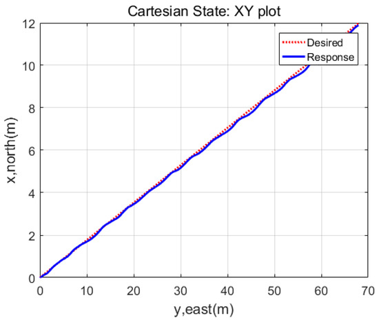
Figure 7.
XY plot of the responses when noise-handling algorithm was not applied. The responses exhibited chattering behaviors due to the influence of measurement noise on the TDE.
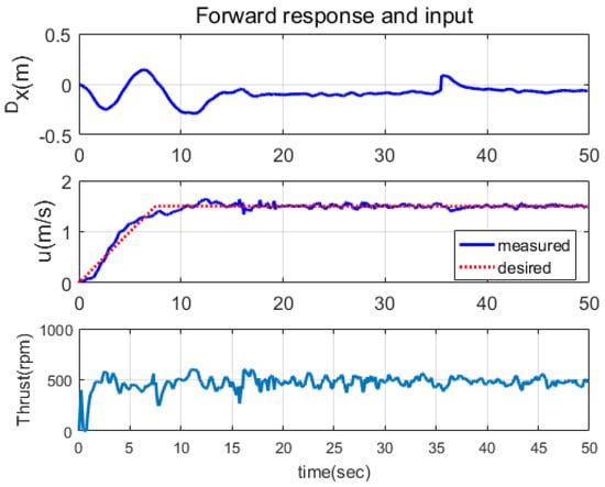
Figure 8.
Forward direction responses when noise-handling algorithm was not applied. The responses were stable; however, there was some minor chattering in the control input.
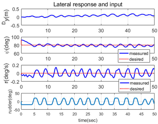
Figure 9.
Lateral direction responses when noise-handling algorithm was not applied. The control input switched frequently, leading to chattering responses in r, , and .
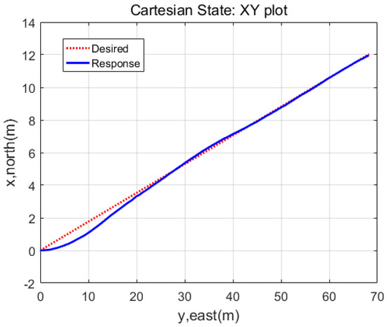
Figure 10.
XY plot of the responses when noise-handling algorithm in Figure 4 was applied. The responses smoothly converged to the desired trajectories even in the presence of an initial angular error.
4.2. Experimental Verification of Tracking Performance in 3D Space Motion
The trajectory tracking performance of the proposed controller in 3D space motion was verified experimentally. As shown in Figure 13, the desired trajectory, drawing the shape of the number eight, was applied. The experimental results are presented in Figure 13, Figure 14, Figure 15, Figure 16 and Figure 17. Figure 13 and Figure 14 show the tracking responses in the world coordinate , demonstrating that the controlled system had stable responses and followed the desired trajectory with bounded errors. The root mean square (RMS) errors in Table 1 indicate that the tracking performances were accurate enough to perform surveying missions requiring tracking errors of less than one meter. It can be observed from Table 1 that the RMS error in the vertical direction was slightly larger than those in the other directions due to buoyancy acting as a disturbance in the vertical direction. Figure 15, Figure 16 and Figure 17 show the responses and control inputs for each direction. Note that in Figure 17, the response of exhibited a large tracking error induced by the controller to reduce the tracking error of z. In Figure 15, it can be observed that the tracking error of bounced around at times t = 66 s, 87 s, and 141 s, which was caused by irregular DVL signals resulting from stiff changes in the seabed.
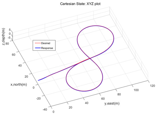
Figure 13.
XYZ plot of the tracking responses.
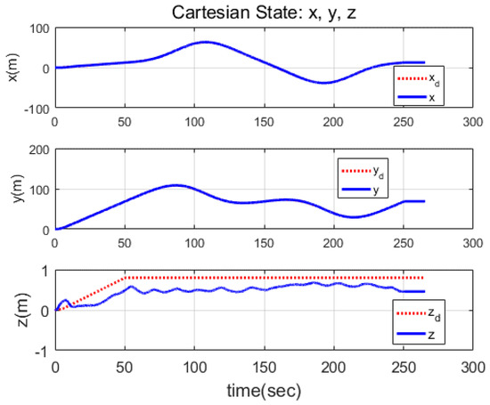
Figure 14.
The time responses of the positions in a Cartesian space.
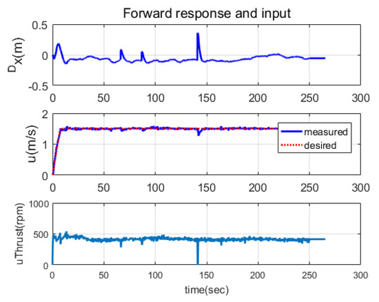
Figure 15.
The responses and actuation in the forward direction. converged to zero because, as explained in Equation (8), the desired trajectory expressed in the desired trajectory coordinate was zero. The responses of and u followed their desired trajectories smoothly, demonstrating the effectiveness of the noise filtering depicted in Figure 4. That aside, the tracking response of bounced around at times s, 87 s, and 141 s, which was caused by irregular DVL signals resulting from stiff changes in the seabed.
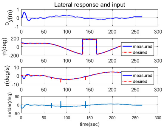
Figure 16.
The responses and actuation in the lateral direction. The responses of , , and r followed their desired trajectories smoothly, demonstrating the effectiveness of the noise filtering depicted in Figure 4. The responses did not exhibit any significant chattering, in contrast to the responses in Figure 9, which represents the case without noise filtering.
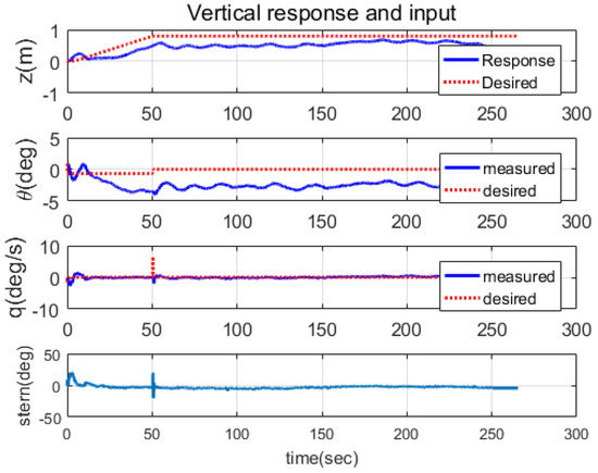
Figure 17.
The responses and actuation in the vertical direction. The responses of z, , and q followed their desired trajectories smoothly. The response of z showed a steady state error because the buoyancy acted as disturbances in the vertical direction. The error of induced a reduction in the error of z, corresponding to the desired error dynamics in (14). The responses having non-zero errors were matched with the error dynamics analysis in Equations (22a)–(22c), which explains that the proposed controller may not converge to zero if there are non-zero disturbances on the vehicle dynamics.

Table 1.
The root mean square (RMS) errors in .
5. Conclusions
In this paper, we proposed a trajectory tracking controller for AUVs in 3D space motion, along with experimental verification on the sea. The main concept of the proposed controller is to design the desired error dynamics that combine the state variables in the body-fixed coordinate and the world coordinate (i.e., the desired trajectory coordinate) to address the underactuated nature of the vehicle. The TDE, an indirect estimation method utilizing control inputs and vehicle outputs, was employed to estimate the nonlinear dynamics and disturbances of the vehicle. Consequently, the proposed controller is relatively easy to implement as it does not require the entire dynamic model of the vehicle. In terms of experimental implementation, the controller is relatively easy to stabilize since it only requires the first derivatives of the states and the states themselves, thereby potentially mitigating noise amplification arising from differentiation. Practical issues related to implementation in experimental environments were also addressed. A noise-filtering algorithm for the TDE was developed, and compensation methods for the mechanical limitations and nonlinear dynamics of the actuators were devised. The performance of the proposed controller was validated through experiments in seawater. The experimental results demonstrate the effectiveness of the noise-filtering algorithm in stabilizing the control performance. Through trajectory tracking control experiments in 3D space motion, it was verified that the proposed controller achieves accurate tracking performance, rendering it suitable for survey missions requiring precise tracking performance with errors of less than one meter.
Author Contributions
Conceptualization, G.R.C. and J.-H.L.; methodology, G.R.C.; software, G.R.C. and H.K. (Hyungjoo Kang); validation, G.R.C., H.K. (Hyungjoo Kang), M.-G.K., M.-J.L., H.K. (Hosung Kim), H.L. and G.L.; formal analysis, G.R.C.; investigation, G.R.C.; resources, J.-H.L.; data curation, G.R.C.; writing—original draft preparation, G.R.C.; writing—review and editing, G.R.C.; visualization, G.R.C.; supervision, G.R.C.; project administration, G.R.C.; funding acquisition, G.R.C. All authors have read and agreed to the published version of the manuscript.
Funding
This research was supported by the Korea Institute of Marine Science & Technology Promotion (KIMST) and funded by the Ministry of Oceans and Fisheries of Korea (20220567, Development of standard manufacturing technology for marine leisure vessels and safety support robots for underwater leisure activities).
Institutional Review Board Statement
Not applicable.
Informed Consent Statement
Not applicable.
Data Availability Statement
Data are contained within the article.
Conflicts of Interest
The authors declare no conflict of interest.
Abbreviations
The following abbreviations are used in this manuscript:
| AUV | Autonomous underwater vehicle |
| BC | Back-stepping control |
| BCTDE | Back-stepping control with time delay estimation |
| TDE | Time delay estimation |
| DOF | Degree of freedom |
| IMU | Inertial measurement unit |
| DVL | Doppler velocity log |
| GNSS | Global navigation satellite system |
| RMS | Root mean square |
References
- Khalil, H.K. Nonlinear Systems, 3rd ed.; Prentice Hall: Hoboken, NJ, USA, 2002. [Google Scholar]
- Cho, G.R.; Li, J.H.; Park, D.; Jung, J.H. Robust trajectory tracking of autonomous underwater vehicles using back-stepping control and time delay estimation. Ocean Eng. 2020, 201, 107131. [Google Scholar] [CrossRef]
- Li, J.H.; Lee, P.M. Path tracking in dive plane for a class of torpedo-type underactuated AUVs. In Proceedings of the 7th Asian Control Conference, ASCC 2009, Hong Kong, China, 27–29 August 2009; pp. 360–365. [Google Scholar]
- Repoulias, F.; Papadopoulos, E. Planar trajectory planning and tracking control design for underactuated AUVs. Ocean Eng. 2007, 34, 1650–1667. [Google Scholar] [CrossRef]
- Liang, X.; Qu, X.; Hou, Y.; Zhang, J. Three-dimensional path following control of underactuated autonomous underwater vehicle based on damping backstepping. Int. J. Adv. Robot. Syst. 2017, 14, 1729881417724179. [Google Scholar] [CrossRef]
- Juan, L.; Zhang, Q.; Cheng, X.; Mohammed, N.F. Path following backstepping control of underactuated unmanned underwater vehicle. In Proceedings of the 2015 IEEE International Conference on Mechatronics and Automation (ICMA), Beijing, China, 2–5 August 2015; pp. 2267–2272. [Google Scholar]
- Cho, G.R.; Park, D.G.; Kang, H.; Lee, M.J.; Li, J.H. Horizontal Trajectory Tracking of Underactuated AUV using Backstepping Approach. IFAC-PapersOnLine 2019, 52, 174–179. [Google Scholar] [CrossRef]
- Cho, G.R.; Kang, H.; Lee, M.J.; Kim, M.G.; Li, J.H. 3D Space Trajectory Tracking of Underactuated AUVs using Back-Stepping Control and Time Delay Estimation. IFAC-PapersOnLine 2021, 54, 238–244. [Google Scholar] [CrossRef]
- Elmokadem, T.; Zribi, M.; Youcef-Toumi, K. Terminal sliding mode control for the trajectory tracking of underactuated Autonomous Underwater Vehicles. Ocean Eng. 2017, 129, 613–625. [Google Scholar] [CrossRef]
- Yu, C.; Xiang, X.; Lapierre, L.; Zhang, Q. Nonlinear guidance and fuzzy control for three-dimensional path following of an underactuated autonomous underwater vehicle. Ocean Eng. 2017, 146, 457–467. [Google Scholar] [CrossRef]
- Karkoub, M.; Wu, H.M.; Hwang, C.L. Nonlinear trajectory-tracking control of an autonomous underwater vehicle. Ocean Eng. 2017, 145, 188–198. [Google Scholar] [CrossRef]
- Yang, X.; Yan, J.; Hua, C.; Guan, X. Trajectory Tracking Control of Autonomous Underwater Vehicle with Unknown Parameters and External Disturbances. IEEE Trans. Syst. Man Cybern. Syst. 2019, 51, 1054–1063. [Google Scholar] [CrossRef]
- Elmokadem, T.; Zribi, M.; Youcef-Toumi, K. Control for dynamic positioning and way-point tracking of underactuated autonomous underwater vehicles using sliding mode control. J. Intell. Robot. Syst. 2019, 95, 1113–1132. [Google Scholar] [CrossRef]
- Yan, Z.; Wang, M.; Xu, J. Robust adaptive sliding mode control of underactuated autonomous underwater vehicles with uncertain dynamics. Ocean Eng. 2019, 173, 802–809. [Google Scholar] [CrossRef]
- Tabataba’i-Nasab, F.S.; Keymasi Khalaji, A.; Moosavian, S.A.A. Adaptive nonlinear control of an autonomous underwater vehicle. Trans. Inst. Meas. Control 2019, 41, 3121–3131. [Google Scholar] [CrossRef]
- Li, J.; Du, J.; Sun, Y.; Lewis, F.L. Robust adaptive trajectory tracking control of underactuated autonomous underwater vehicles with prescribed performance. Int. J. Robust Nonlinear Control 2019, 29, 4629–4643. [Google Scholar] [CrossRef]
- Wang, J.; Wang, C.; Wei, Y.; Zhang, C. Three-Dimensional Path Following of an Underactuated AUV Based on Neuro-Adaptive Command Filtered Backstepping Control. IEEE Access 2018, 6, 74355–74365. [Google Scholar] [CrossRef]
- Li, J.H.; Lee, M.J.; Kang, H.; Kim, M.G.; Cho, G.R. Neural-net based robust adaptive control for 3D path following of torpedo-type AUVs. In Proceedings of the 2020 59th IEEE Conference on Decision and Control (CDC), Jeju Island, Republic of Korea, 14–18 December 2020; pp. 5261–5266. [Google Scholar]
- Jun, B.H.; Park, J.Y.; Lee, F.Y.; Lee, P.M.; Lee, C.M.; Kim, K.; Lim, Y.K.; Oh, J.H. Development of the AUV ‘ISiMI’and a free running test in an Ocean Engineering Basin. Ocean Eng. 2009, 36, 2–14. [Google Scholar] [CrossRef]
- Rout, R.; Subudhi, B. NARMAX self-tuning controller for line-of-sight-based waypoint tracking for an autonomous underwater vehicle. IEEE Trans. Control Syst. Technol. 2016, 25, 1529–1536. [Google Scholar] [CrossRef]
- Refsnes, J.E.; Sorensen, A.J.; Pettersen, K.Y. Model-based output feedback control of slender-body underactuated AUVs: Theory and experiments. IEEE Trans. Control Syst. Technol. 2008, 16, 930–946. [Google Scholar] [CrossRef]
- Healey, A.J.; Lienard, D. Multivariable sliding mode control for autonomous diving and steering of unmanned underwater vehicles. IEEE J. Ocean. Eng. 1993, 18, 327–339. [Google Scholar] [CrossRef]
- Fossen, T.I. Guidance and Control of Ocean Vehicles; John Wiley & Sons Inc.: Hoboken, NJ, USA, 1994. [Google Scholar]
- Park, D.; Li, J.H.; Ki, H.; Kang, H.; Kim, M.G.; Suh, J.H. Selective AUV guidance scheme for structured environment navigation. In Proceedings of the OCEANS 2019—Marseille, Marseille, France, 17–20 June 2019; pp. 1–5. [Google Scholar]
- González-García, J.; Gómez-Espinosa, A.; García-Valdovinos, L.G.; Salgado-Jiménez, T.; Cuan-Urquizo, E.; Escobedo Cabello, J.A. Experimental Validation of a Model-Free High-Order Sliding Mode Controller with Finite-Time Convergence for Trajectory Tracking of Autonomous Underwater Vehicles. Sensors 2022, 22, 488. [Google Scholar] [CrossRef]
- Dai, X.; Xu, H.; Ma, H.; Ding, J.; Lai, Q. Dual closed loop AUV trajectory tracking control based on finite time and state observer. Math. Biosci. Eng. 2022, 19, 11086–11113. [Google Scholar] [CrossRef] [PubMed]
- Borlaug, I.L.G.; Pettersen, K.Y.; Gravdahl, J.T. Comparison of two second-order sliding mode control algorithms for an articulated intervention AUV: Theory and experimental results. Ocean Eng. 2021, 222, 108480. [Google Scholar] [CrossRef]
- Guerrero, J.; Torres, J.; Creuze, V.; Chemori, A. Trajectory tracking for autonomous underwater vehicle: An adaptive approach. Ocean Eng. 2019, 172, 511–522. [Google Scholar] [CrossRef]
- Kim, J.; Joe, H.; Yu, S.c.; Lee, J.S.; Kim, M. Time-delay controller design for position control of autonomous underwater vehicle under disturbances. IEEE Trans. Ind. Electron. 2015, 63, 1052–1061. [Google Scholar] [CrossRef]
- Cho, G.R.; Chang, P.H.; Park, S.H.; Jin, M. Robust tracking under nonlinear friction using time-delay control with internal model. IEEE Trans. Control Syst. Technol. 2009, 17, 1406–1414. [Google Scholar]
- Cho, G.R.; Park, D.G.; Li, J.H.; Kang, H.; Kim, M.G. Path Tracking Control of AUV using Nonholonomic Error Dynamics. In Proceedings of the 18th International Conference on Control, Automation and Systems (ICCAS 2018), PyeongChang, Republic of Korea, 17–20 October 2018; pp. 271–275. [Google Scholar]
- Hanwha Systems. Unmanned Maritime System. Available online: https://www.hanwhasystems.com/en/business/defense/naval/marine_index.do (accessed on 21 June 2023).
- Kang, H.; Cho, G.R.; Kim, M.G.; Lee, M.J.; Li, J.H.; Kim, H.S.; Lee, H.; Lee, G. Mission Management Technique for Multi-sensor-based AUV Docking. J. Ocean Eng. Technol. 2022, 36, 181–193. [Google Scholar] [CrossRef]
- Lee, G.; Lee, P.Y.; Kim, H.S.; Lee, H.; Lee, J. Learning-based Localization of AUV with Outlier Sensor Data. In Proceedings of the 2021 21st International Conference on Control, Automation and Systems (ICCAS), Jeju, Republic of Korea, 12–15 October 2021; pp. 2257–2260. [Google Scholar]
- Kim, G.; Lee, J.; Lee, P.; Kim, H.; Lee, H. A study on docking guidance navigation algorithm of AUV by combining inertial navigation sensor and docking guidance sensor. J. Inst. Control. Robot. Syst. 2019, 25, 647–656. [Google Scholar] [CrossRef]
- Choi, K.; Lee, G.; Lee, P.Y.; Kim, H.S.; Lee, H.; Kang, H.; Lee, J. Localization algorithm of multiple-AUVs utilizing relative 3D observations. J. Korea Robot. Soc. 2022, 17, 110–117. [Google Scholar] [CrossRef]
- Wang, J.; Wang, C.; Wei, Y.; Zhang, C. On the fuzzy-adaptive command filtered backstepping control of an underactuated autonomous underwater vehicle in the three-dimensional space. J. Mech. Sci. Technol. 2019, 33, 2903–2914. [Google Scholar] [CrossRef]
- Xia, Y.; Xu, K.; Li, Y.; Xu, G.; Xiang, X. Improved line-of-sight trajectory tracking control of under-actuated AUV subjects to ocean currents and input saturation. Ocean Eng. 2019, 174, 14–30. [Google Scholar] [CrossRef]
- Peng, Z.; Wang, J.; Han, Q.L. Path-following control of autonomous underwater vehicles subject to velocity and input constraints via neurodynamic optimization. IEEE Trans. Ind. Electron. 2018, 66, 8724–8732. [Google Scholar] [CrossRef]
- Craig, J.J. Introduction to Robotics: Mechanics and Control; Addision Wesley: Boston, MA, USA, 1989. [Google Scholar]
- Youcef-Toumi, K.; Ito, O. A time delay controller for systems with unknown dynamics. J. Dyn. Syst. Meas. Control 1990, 112, 133–142. [Google Scholar] [CrossRef]
- Hsia, T.; Gao, L. Robot manipulator control using decentralized linear time-invariant time-delayed joint controllers. In Proceedings of the IEEE International Conference on Robotics and Automation, Cincinnati, OH, USA, 13–18 May 1990; pp. 2070–2075. [Google Scholar]
- Cho, G.R.; Kang, H.; Lee, M.J.; Li, J.H. Heading Control of URI-T, an Underwater Cable Burying ROV: Theory and Sea Trial Verification. J. Ocean Eng. Technol. 2019, 33, 178–188. [Google Scholar] [CrossRef]
- Chang, P.H.; Park, S.H. The development of anti-windup scheme and stick-slip compensator for time delay control. In Proceedings of the 1998 American Control Conference. ACC (IEEE Cat. No.98CH36207), Philadelphia, PA, USA, 26 June 1998; Volume 6, pp. 3629–3633. [Google Scholar]
Disclaimer/Publisher’s Note: The statements, opinions and data contained in all publications are solely those of the individual author(s) and contributor(s) and not of MDPI and/or the editor(s). MDPI and/or the editor(s) disclaim responsibility for any injury to people or property resulting from any ideas, methods, instructions or products referred to in the content. |
© 2023 by the authors. Licensee MDPI, Basel, Switzerland. This article is an open access article distributed under the terms and conditions of the Creative Commons Attribution (CC BY) license (https://creativecommons.org/licenses/by/4.0/).
