1. Introduction
Recently, the number of studies on unmanned surface vehicles (USV) has attracted much attention in the marine technology field. In fact, one of the premises of USV is generating the ship planning route (SPR) automatically. Then, the ship can track the route and arrive at the destination safely.
The ship route planning problem is a sub-field of route planning, where various algorithms and strategies were proposed and applied.
At first, there was a large number of studies on algorithms based on graphs. Reference [
1] proposed the Dijkstra algorithm to address two problems in the route planning field: (1) Refer to a data structure that consists of paths connecting any two points; (2) Find the optimal path with a minimum total length between two given nodes. Then, the Dijkstra algorithm was employed and improved to solve practice issues. To solve the route planning problem involving the length of paths, a novel algorithm was created based on the Dijkstra algorithm, which referred to fuzzy theory [
2]. Except the length of paths, time costs were also considered in [
3,
4], where traditional Dijkstra was improved. Furthermore, there were also various studies on the ship route planning problem employing the Dijkstra algorithm. There were also researchers who created a three-dimensional Dijkstra algorithm that supported the ship to plan the motion in which the speeds and courses were determined at each second [
5]. Generating global optimum solutions for ship routes was expected. Moreover, the weather was also taken as an index of the Dijkstra algorithm when planning the minimum time cost for a route [
6].
Then, based on the Dijkstra algorithm, a novel method called A* was also proposed and improved. In the original A* algorithm, the path was connected by the vertices of the grid map used, which means that the length of the route was not optimal. Therefore, Theta* was applied to [
7] to make up for the drawback. Moreover, to save searching time, time-efficient A* was employed in [
8] and simulated successfully. To address route planning problems, researchers considered multiple factors when applying the A* algorithm. For example, collision avoidance, rules on the sea, and the motion characteristics of ships were taken as examples [
9]. Moreover, some researchers even considered the space characteristics of the ship [
10].
Moreover, sampling theory was also extended and applied to route planning problems. RRT (rapid-exploring random tree) is a common algorithm used in the field of path planning. The RRT algorithm is completed in probability if reaches 100% if enough time is given for exploration. The main idea is to construct the searching tree and find line segments connecting the start point to the destination. Compared to other sample-based algorithms, not only does the RRT* have their advantages but it also has a higher degree of freedom [
11]. Moreover, there were several algorithms that were generated based on the RRT algorithm. For instance, the RRT* is a kind of sample-based algorithm, which optimized the length of the route given by the RRT algorithm. In reference [
12], the RRT* was compared with the A* via simulations to illustrate their advantages and disadvantages. In fact, the RRT* had been improved in various ways, taking into account different optimization goals or environmental conditions. To solve the field programmable gate arrays problem, the RRT* was improved to consider the terrain, planning speed, etc., [
13]. Furthermore, a novel series of improved RRT* algorithms, named Quick-RRT*, PQ-RRT*, and P-RRT* were proposed by researchers [
14,
15]. All of them focused on fast speed converges to improve the characteristic of the route planning module of the ship. To do so, they combined the RRT* and potential function to give a better solution with a fast speed of convergence. Except for the above algorithms, the Connect-RRT algorithm was also developed to plan routes with fast speed [
16]. In fact, the Connect RRT algorithm maintains two trees: one of them started from the departure point and another began from the destination. When the two trees encountered each other during the searching process, the route planning task could be ended. Based on that, various studies imitating the principle of Connect-RRT emerged, such as RRT*-connect [
17], bidirectional potential guided RRT* [
18], informed RRT*-connect [
19], smooth RRT-connect [
20], and so on.
RRT and its extended methods in the marine technology field (ship route planning) was applied to generate planned routes in a canal [
21]. In such area, the current had to be considered, as is reasonable, as it would affect the navigation safety of ships. Moreover, the rule of local governments regarding canal navigation shall be also considered to avoid collisions between surface vehicles. To make up for the disadvantages of the RRT algorithm, reference [
22] gave a hybrid step size and target attractive force RRT algorithm, which mainly improved the accuracy of the planned route in narrow waters. Moreover, the RRT algorithm was developed to have abilities of enhanced adaptability in [
23]. Furthermore, it was necessary to include regulations when considering the route planning algorithm. Based on that, reference [
24] gave a novel algorithm that combined the rule on the sea. Moreover, reference [
25] gave the Bi-RRT algorithm, which can make decisions when faced with obstacles to prevent collisions.
Recently, with the development of artificial intelligence, many researchers have started using the reinforce leaning theory to address route planning problems [
26,
27,
28]. For instance, the algorithm called deep reinforcement learning was provided in [
29] to solve collision avoidance problem and optimize the length of the route at the same time. Moreover, the reinforcement learning algorithm was also engaged in unsupervised learning [
30].
Different from robots and other vehicles, the navigation safety of ships involves two factors: water depth and obstacles. It means that the SPR could not cross land, reefs, and shallow water areas. However, few of the above studies consider both factors. Instead, they paid more attention to avoiding obstacles. Moreover, it is well-known that SPR is a polyline. However, the ship could not follow polylines accurately because of kinetic constraints [
31]. Therefore, it is essential to consider ship motion characteristics in waypoint areas in optimization. In addition, most of the studies reviewed employed grid maps as configuration spaces. It means that converting from ENC or other sources of charts to raster maps should be conducted in advance. Errors occurred during such processes.
To make up for the above drawbacks, this study proposes a novel approach called the VK-RRT* algorithm. The main contributions of it are as follows:
(1) Unlike in most research, ENC vector data are utilized instead of simulated environmental data or raster map data. The use of vector data could reduce errors emerging from the raster map data process and could also accelerate the application of the path planning algorithm in navigational practice;
(2) We propose a novel strategy for the implementation of the path planning algorithm to account for ship kinetic constraints. Under constant speed, turning trajectories in the form of arcs are predicted and checked for safety in the path planning process. The strategy could largely decrease the pressure of controllers to track the planed path in the turning area;
(3) Compared to RRT and RRT* algorithms, the VK-RRT* method could give solutions faster.
The remainder of this study is arranged as follows:
Section 2 presents the preliminary knowledge involved in this study.
Section 3 gives RRT, RRT*, and the proposed VK-RRT* algorithm descriptions in detail for readers to compare and understand.
Section 4 presents two case studies to illustrate the advantages and effectiveness of the proposed algorithm.
Section 5 gives some conclusions and drawbacks, which need to be addressed in near future.
2. Preliminary Knowledge
In this section, we give the definition of the route planning of ships, motion constrains considered, and the Delaunay triangulation explanations used in our algorithms.
2.1. Problem Definition
This section presents the ship route planning problem that is investigated in this study. Let be the configuration space where ships navigate where . In addition, there are two sub-spaces and in , which represent the obstacle space and the free space of navigation, respectively. represents the initial position, whereas is the position of the destination that is to be reached. Path is a continuous function and it has bounded variation. Moreover, is free of collision when , .
Ship route planning problem: It is designed to safely find a proper or optimal guiding ship from the departure position to the destination.
Additionally, the three sub-problems are defined as follows:
Sub-problem 1. Considering a triplet , generate a feasible route if there is one. Otherwise, report failure.
For ship navigation, the shorter route means less cost. Therefore, this study also considers route optimization in the process of planning. Let be the set of all routes and be the set of all feasible routes.
Sub-problem 2. Considering a triplet , define a cost function and find a feasible route , such as . Report failure if there is no .
Sub-problem 3. Considering a triplet , define a cost function and find a feasible route , such as , and find out if it is feasible to follow , considering ship motion characteristics. Report failure if there is no .
2.2. ENC Vector Data
To address the above problems, electronic nautical chart (ENC) vector data are employed to generate configuration space without rasterization. This type of chart could be used in the marine field, such as in navigation, fishing, etc.
According to the International Hydrographic Organization (IHO) S57 standard [
32], ENC data consist of a certain amount of features that play a vital role in navigation. However, in this study, sound/depth in
, land, reef or other static obstacles instead of all the features in ENC are employed in
to generate a planning route. In short, this study only considers the effects of depth and obstacle positions on the route planning problem.
Before implementing the ENC vector data, it is important to clarify the types of data. In ENC, an object is defined as an identifiable set of information. An object may have attributes and may be related to other objects. Feature objects have descriptive attributes but no geometry (i.e., information about the shape and position of a real-world entity). Spatial objects may have descriptive attributes and must have geometry. To be specific, there are three elements that represent geometry: point, line, and area.
In the proposed algorithm, ENC data are employed to form the configuration space . Obstacle areas make up while depth points compose .
2.3. Ship Motion Characteristics
The motion characteristics of a vessel refer to the physical phenomena that describe the vessel’s movements and behaviors on a waterway. These characteristics are influenced by several factors, including the physical characteristics of a vessel, such as its size, shape, weight, speed, and the hydrodynamic conditions of the water through which it moves. In particular, the motion of a vessel can be characterized by its heave (vertical motion), pitch (rotational motion around the transverse axis), roll (rotational motion around the longitudinal axis), and yaw (rotational motion around the vertical axis). These motions are indicative of the vessel’s dynamic behavior and are influenced by external forces, such as wind, waves, and currents. A thorough understanding of the motion characteristics of a vessel is essential for ensuring the safe and efficient operation of a marine craft.
For route planning control problems, the turning constraint are usually taken into consideration. To be specific, when a ship alters its course, its trajectory is an arc. While most routes designed by researchers are presented as broken lines, straight line segments are connected in sequence. It is possible that ships ground in waypoint areas. Therefore, we have to take ship motion into account for safety purposes.
In order to simulate the ship motions, the MMG model is applied in this paper and
Table 1 gives explanation of the variables used in Equations (1) and (2).
Reference [
33] gives more information about this model.
2.4. Delaunay Triangulation
The Delaunay triangulation is a geometric algorithm that constructs a triangulation using a set of points in a plane, where each triangle in the triangulation satisfies the Delaunay criterion; no point in the point set is inside the circumcircle of any triangle. This feature ensures that the triangulation avoids forming skinny triangles, which is advantageous for various applications, such as mesh generation and image processing.
In practice, there are many situations that we need in order to design routes using discrete points. The Delaunay triangulation (DT) method is such a method that can be used to solve the above problem. In electronic nautical charts, the depth points are unordered and discrete. The DT method could reconstruct them as the initial map for route planning.
The principle of DT is simple: for a given set
P, any two points could construct an edge of DT map when there is a circle above two points and there is no other point in the circle [
34].
It should be made clear that different ways of generating maps largely affect the planed route. In this paper, we only discuss the effectiveness of the proposed algorithm.
3. Route Planning Algorithm
In this section, we propose the VK-RRT* algorithm for the route planning problem of USV. Based on traditional RRT and considering motion constraints, the VK-RRT* could be applied using data from the ECDIS platform, which has great potential for commercial realisation.
3.1. Rapid-Exploring Random Tree
Rapid-exploring random tree (RRT) is a conventional algorithm in the field of path planning. It gives feasible solutions faster than other methods, such as A*, genetic algorithm (GA). Therefore, in this study, we improve RRT to VK-RRT* to produce a planned route quickly. In fact, RRT is a data structure. It will be sampled in the configuration space , and connect adjacent points constructing tree .
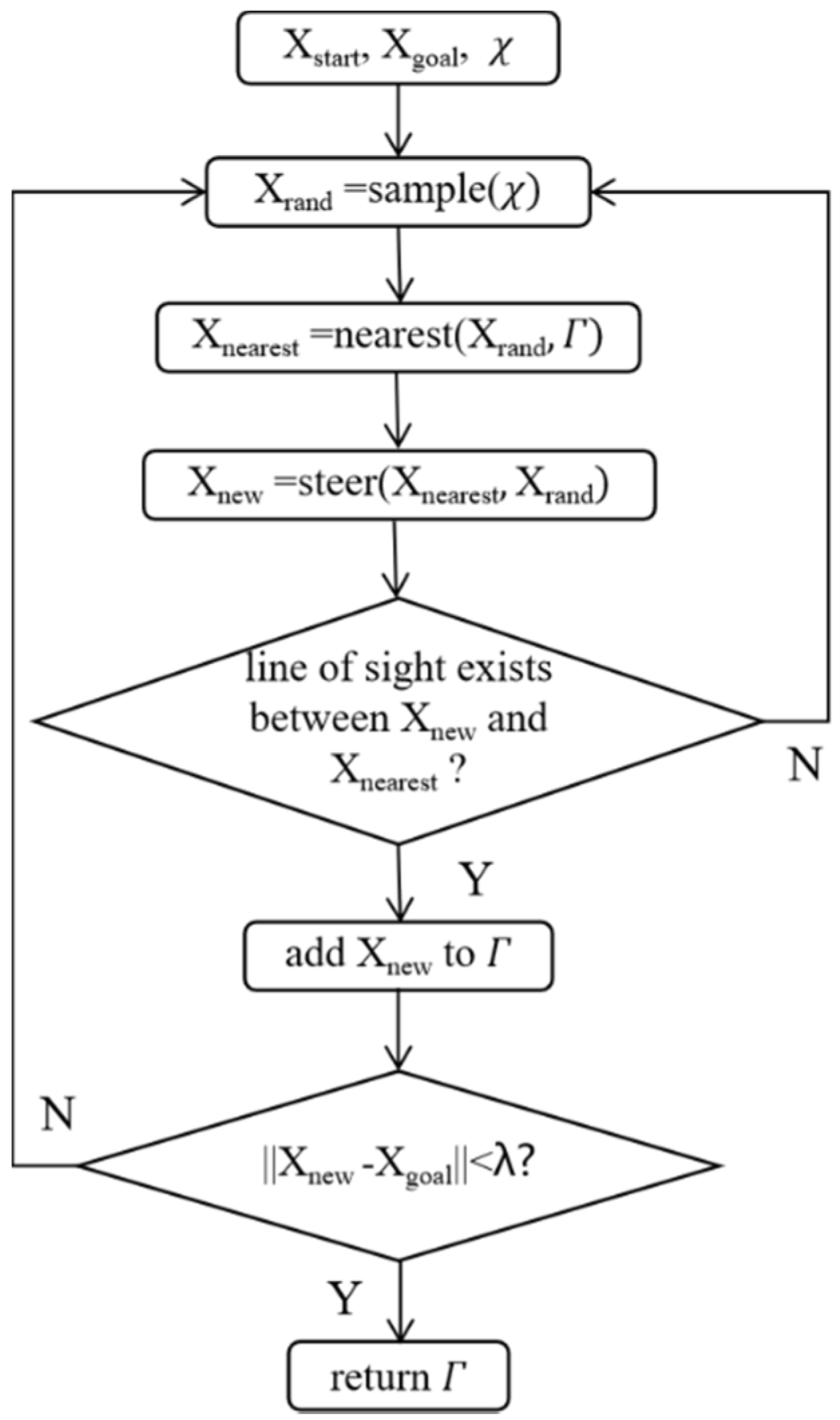
Figure 1 shows the working principles of the RRT algorithm. The function
sample() will randomly find a point from space
; nearest() is responsible for selecting the nearest node from X
rand in tree
; steer() gives the X
new according to X
rand and X
nearest.
Theoretically, the RRT algorithm could find feasible paths connecting departure points and destinations if time cost is not considered, which means that the algorithm reaches 100%. However, the RRT algorithm cannot be used in practical applications because the given path is in the form of a polyline, making it impossible to track ships.
Therefore, the RRT* algorithm has been proposed by previous researchers to improve it.
Figure 2 describes the RRT* algorithm. The difference between RRT and RRT* is that there is a rewire function in the RRT* algorithm. It optimizes the relationships of nodes in
to reduce the account of nodes.
3.2. VK-RRT* Algorithm
Taking ship motion characteristics into account, we propose the VK-RRT* algorithm.
Before introducing the algorithm, the usage of the Delaunay triangulation is illustrated. The depth points
and obstacle positions are extracted from the electronic nautical chart. There are five attributes of
: (
,
) represents the latitude and longitude;
denotes the depth value;
is minimum depth of around
;
means the minimum distance from adjacent objects. Similarly, to enlarge the waypoints data set, we also created
to represent the nodes in the center of every triangular (
Figure 3 and
Figure 4).
By obtaining data sets of depth points and obstacles, Delaunay triangulation is applied for generating the DT map, which is represented as . It is noted that there are two areas in space : free space and obstacle space . and make up the configuration space .
Figure 5 describes the working principle of VK-RRT*. Except for the data process, the rewire module is different from traditional RRT*, as it considers ship motion characteristics.
As shown in
Figure 6, the dark blue line is the route given by RRT*. However, it is impossible for surface ships to track the polyline as the large inertia.
Moreover, ships may encounter dangers in waypoint areas, as such in areas that have not been checked for safety in the route planning stage.
In fact, when the ship changes its course, the trajectory will be an arc line. Therefore, arc line segments in waypoint areas are designed. Navigating along the arc line, the ship only needs to give a fixed rudder angle to achieve tracking.
For example,
Figure 7 shows the sketch map. The route
is not suitable for a ship to track. Instead, we used
to replace it. The new route is determined by using Equations (1) and (2).
Specifically, the main task is to determine the distance of
:
. We suggest the following equations
where
DN is the function used to measure the direction of a vector from the north;
R is the turning radius determined by Equations (1) and (2).
Then, we can obtain the latitude and longitude of
and
.
In detail, VK-RRT* could plan the route that satisfies the requirement of ship motion constraints.
4. Simulation and Analysis
In order to verify the effectiveness and advantages of VK-RRT*, we carried out two simulations. Moreover, in our tests, we used the ships described in [
33]. In the first scenario, we aimed to examine the ability of the proposed algorithm to plan route passing through narrow channels. In the second scenario, we tried to examine it in an open area. In each experiment, we compared the proposed algorithm with the RRT and RRT* algorithms to present the advantages of our algorithm. Both experiments have been conducted on ECDIS platform, which means that the frame we propose could be applied after professional packaging.
Moreover, in the process of choosing new points, we could add goal orientation to accelerate the search. This kind of strategy has been extensively studied in [
35,
36,
37,
38,
39,
40].
where
is a random number,
is set parameter of the adjustment.
4.1. Simulation in Islands
In this simulation, we use the electronic nautical chart numbered “US5M16IM.000”, shown in
Figure 8.
First, the positions of the departure point and destination are (89.909° W, 45.924° N) and (83.853° W, 46.924° N) separately. Moreover, we assume that the ship will steer in a rudder angle of altering its course. In this experiment, the ability to search the route passing through narrow channels is mostly validated.
The results are illustrated in
Figure 9,
Figure 10,
Figure 11,
Figure 12 and
Figure 13, in which the red line is the planned route given by algorithms with different strategies; the blue lines construct the rapid-explore random tree, and the black lines represent the search process.
Specifically, in
Figure 9a, the RRT algorithm gives the planning route in 170 s. It sampled the entire area and constructed bigger trees compared to other algorithms. The length of the route is 22.62 nautical miles, with 84 waypoints. Then, in
Figure 9b, the RRT* spends 167.24 s to plan the route. Because of its advance, the length of the route is 19.65, which is shorter than that given by the RRT algorithm. The result of the proposed algorithm is shown in
Figure 9c. The time cost has been reduced significantly and it only took 129.41 s to provide the planned route. The length of that route is also the shortest: 18.72 nautical miles. We can also observe that in the proposed algorithm, most of nodes searched were lump together, which improves search effectiveness.
Figure 10 illustrates the results of comparisons of the RRT, RRT*, and proposed algorithms considering goal orientations. The time consumed using the above three algorithms is reduced significantly compared to the algorithms without goal orientation. Their time costs are 41.47 s, 161.72 s, and 39.81 s, respectively. The lengths of the routes are 19.55 nm, 18.91 nm, and 18.71 nm.
Moreover, we should also focus on the characteristics of the waypoint areas. In such places, ships will alter their courses, which could not be tracked by the route planned by the RRT and RRT* algorithms, as both of them create a polyline-based route.
Figure 11 shows the planned route on an electronic nautical chart. It is noticeable that the planned route consists of straight-line segments and arc-line segments. In waypoint areas, the route guides ship navigation from a straight line segment to another line segment in an arc-shaped trajectory. This kind of route takes ship motion characteristics into account. The arc line segments are checked for safety in the search process to could ensure safety.
To be specific, in navigation practice, the planned route was not considered by route optimization in waypoints areas. In previous studies, many researchers have used different kinds of technologies to smooth out the route, making it smoother to track. However, for ship control engineers, it is difficult to design a controller that could track curves well, especially considering the large inertia of ships. Instead, our strategy could let ship navigate at a fix rudder angle to track arc lines as they are designed in reference to ship turning trajectories.
4.2. Simulation in the Port
Here, we provide another simulation in the port area to further validate the feasibility of the proposed algorithm. The area is shown as
Figure 12: Dalian Port, China.
In this scenario, the departure point and destination are set as (121.727° E, 38.964° N) and (121.944° E, 39.02° N), respectively. The other parameters of the simulation are the same as those of the first simulation.
Figure 13 and
Figure 14 demonstrate the search process of the RRT, RRT*, and proposed algorithms with or without goal orientation strategy. Without considering goal orientation (shown in
Figure 12), the time cost of RRT, RRT*, and proposed algorithms is 97.08 s, 87.59 s, and 34.01 s, respectively. It is clear that the proposed algorithm has advantages in the time cost index. Moreover, the lengths of the routes of these algorithms are 32.79 nm, 27.45 nm, and 17.57 nm, respectively.
Figure 14 illustrates the planned route given by three algorithms with goal orientation. Their time costs are 26.02 s, 19.94 s, and 9.49 s, respectively. The lengths of the routes given by the RRT, RRT*, and the proposed algorithms are 22.98 nm, 17.73 nm, and 17.22 nm. For the proposed algorithm, the goal orientation strategy only affects the time cost but has little impact on the length of the route.
Similarly, we also show the planned route on the electronic nautical chart for the convenience of analyzing waypoint areas.
We can see that in waypoint areas in
Figure 15, the planned route is optimized to adapt ship motion characteristics.
In this section, we carry out two simulations validating the feasibility and advantages of the proposed algorithm. The result shows that the proposed algorithm meets the requirements of navigation and ensures safety.
5. Conclusions
This study introduces VK-RRT*, a novel algorithm for addressing SPR problems using ENC data. The algorithm uses Delaunay triangulation to organize ENC vector data, and searches for routes within it. Two cases are examined to demonstrate the effectiveness of VK-RRT*.
However, the study has some limitations that need to be addressed in the future. Firstly, this research only considers depth and land/reef areas; other traffic schemes, such as traffic separation, should also be considered. Secondly, local path planning, or collision avoidance, is not considered, which is also an important part for intelligent ships.
Moving forward, future research should focus on addressing these limitations to improve the effectiveness of the algorithm in practical applications. In addition, it is worth developing a route planning model that could be applied on the ECDIS platform. Finally, there should be a focus on local path planning considering dynamic vessels or obstacles if a better global route is to be obtained and smart navigation is to be achieved.


