Article

Experimental Study on Hydrodynamic Characteristics of Barge-Type Breakwaters under Different Mooring Methods

1
School of Civil and Ocean Engineering, Jiangsu Ocean University, Lianyungang 222005, China
2
School of Ocean Engineering, Jiangsu Ocean University, Lianyungang 222005, China
3
Key Laboratory of Ministry of Education for Coastal Disaster and Protection, Hohai University, Nanjing 210098, China
*
Author to whom correspondence should be addressed.
J. Mar. Sci. Eng. 2023, 11(5), 1016; https://doi.org/10.3390/jmse11051016
Submission received: 30 March 2023 / Revised: 27 April 2023 / Accepted: 9 May 2023 / Published: 10 May 2023
(This article belongs to the Section Coastal Engineering)

Abstract

:
In this paper, a yacht project in Tingjiang Town, Mawei, Fujian, is suggested as an example of a barge type breakwater made out of scrap barges. The physical modelling of a two-dimensional flume wave test was carried out on a barge-type breakwater, focusing on the wave dissipation and anchor chain forces under two different mooring methods, the “crossed tilt” mooring and the “front and rear direct pull” mooring, with no change in the size of the breakwater. The test results show that the effect of wave elimination of the barge-type breakwater gradually decreases with the increase of wave elements under different mooring conditions, but the effect of wave elimination of the barge-type breakwater is significantly better under the “crossed tilt” mooring systems than under the “front and rear direct pull” mooring systems; the maximum tension of the anchor chain under the “inner eight” diagonal mooring method is significantly higher than that under the front and rear straight pulling mooring method. The maximum anchor chain tension under the “crossed tilt” mooring system is significantly greater than that under the fore and aft straight mooring method, while the average anchor chain tension does not change significantly under the two mooring methods.

1. Introduction

With the development of the global economy and the rapid rise of the shipping sector in recent years, the number of ships berthing in ports has increased day by day. Breakwaters are constructed in ports to protect ships and port facilities. However, standard sit-on-the-bottom breakwaters are costly, difficult to deploy, and unsuitable for future maintenance. A novel alternative in this context is a form of breakwater known as a floating breakwater. A floating breakwater is a special type of breakwater consisting of a mooring system and a floating body. The floating part is mainly used for wave attenuation and the mooring system is used to secure the upper floating body. As opposed to the typical sit-on-the-bottom breakwater, the floating breakwater can be adapted to deep water and water exchange and can be both permanently and temporarily installed [1]. The floating breakwater is considered to have a wide range of applications due to its many advantages such as ease of installation and ease of maintenance. In 1811, the British port of Plymouth saw the construction of the first wooden floating breakwater, and a Japanese floating breakwater was built in Fukuyama in 1976 [2]. A 352 m long, 28 m wide, and 13,000 tone reinforced concrete square box floating breakwater was built in the port of Rabat, Morocco [3]. In Lianyungang, China, the country’s first floating breakwater was finished in 2002. The windy and choppy waters beneath Qitai Mountain in Lianyungang have been turned into a mariculture area as a result of the 1000 m long floating breakwater [4]. This also demonstrates that floating breakwaters have a wide range of applications.
According to Sutko [5], McCartney [6], Wang Yongxue [7], and others, mooring mechanisms significantly affect floating breakwaters. Headland [8] developed a time domain analysis model and suggested that mooring chain forces in mooring systems could be better analyzed through time domain analysis. However, in recent years, floating breakwater research has concentrated on the upper floating body. Chao-yong He et al. [9] studied the wave dissipation of a rectangular box-type floating breakwater, and the results showed that the relative width of the square box, the relative draft depth and the initial tension of the anchor chain had an impact on the wave dissipation performance of the box-type floating breakwater. Increasing B/L can effectively reduce the transmission coefficient and improve the effect of wave elimination. With the increase of q/d, the transmission coefficient decreases obviously (B: Width L: Length q: Draft d: Water depth). At the same time, reasonable initial tension should be selected according to the wave elements. Chen Cheng et al. [10] found that the addition of wing plates on both sides of the traditional floating square box could provide better wave dissipation in long-period waves, and Chun-Yan Ji et al. [11] proposed a new barrel-shaped breakwater and carried out two-dimensional flume tests, which showed that this cylindrical floating breakwater had better wave dissipation performance than the traditional double-floating box breakwater. Xiaofei Cheng et al. [12] found through numerical simulations that adding an airbag after 0.75 times the wavelength of the floating breakwater could increase the wave dissipation performance of the breakwater, and that the wave dissipation performance would be enhanced as the wave period increased. Xiang-qian Mao et al. [13] carried out wave load analysis on a floating breakwater with an arc-shaped layout based on three-dimensional potential flow theory. The results showed that the arc-shaped breakwater could effectively reduce the first-order wave force and second-order wave force of the floating breakwater structure, which could make the profile load of the structure under oblique waves converge with that under cross-wave conditions. Dong Hao et al. [14] conducted a study on a steel structured floating breakwater, and the results showed that the transmission coefficient of this steel structured breakwater could reach below 0.5 when the wave period was less than 6 s, verifying that this new steel structured floating breakwater has wave dissipation effect. Wan Y. et al. [15] investigated a new type of floating breakwater with a double tube and double plate structure made of HDPE, and the results showed that the transmission coefficient and anchor chain force of this breakwater increased with the increase of wave period. Jiangtao Ge et al. [16] proposed a non-linear layout of the floating breakwater and found that the arc-shaped arrangement of the breakwater performed better hydrodynamically under the action of transverse and oblique waves, and the motion was more stable accordingly. Song-zhe Li et al. [17] studied open floating breakwaters and found that the transmission coefficient of open floating breakwaters gradually decreased as their relative width increased and the anchor chain force applied to them increased significantly with the increase in wave height.
Nonetheless, floating breakwater mooring methods have received less attention than upper attachment experiments. Sutko et al. [5] found through physical modelling experiments that the mooring system was an important part of the floating breakwater problem, both in terms of wave dissipation and in terms of mooring forces, and that the tension on the mooring chain was less when the horizontal mooring was chosen compared to the vertical mooring. Sannasiraj et al. [18] studied floating breakwaters with three different mooring methods (mooring at water level, bottom mooring and bottom cross mooring) and the results showed that the breakwaters had better wave dissipation with bottom cross mooring and the anchor chain force was greater than in the other two methods. Huayang Dong et al. [19] studied the transmission coefficients of three different breakwaters (single pontoon, pontoon and one horizontal layer and pontoon and two horizontal layers) under two different mooring methods, and the results showed that the transmission coefficients of the vertical guide pile mooring method were smaller than those of the anchor chain mooring method, and the transmission coefficients decreased with increasing relative width and number of horizontal layers. Chun-yan Ji et al. [20] used CFD to analyze the slamming load and motion response of floating breakwaters under two mooring methods, namely anchor chain mooring and vertical guide pile mooring, and the results showed that the slamming load was mainly concentrated on the waveward side and increased with wave height and decreased with period. Jia-ming Liang et al. [21] experimentally compared the wave dissipation performance and motion response of square box floating breakwaters under fixed installation and three mooring methods, and the results showed that the fixed method was the best, cross mooring and parallel mooring were the second best, and non-towed parallel mooring was the worst.
In recent years, the structural design of floating breakwaters has received the majority of research attention, while mooring techniques have received less attention. The mooring system, however, is a crucial component of the floating breakwater. The mooring mechanism of floating breakwaters needs to be investigated and optimized in order to adapt floating breakwaters to more complicated sea conditions. Some of these studies, however, have been carried out only for a certain kind of mooring. In order to give a more scientific basis for engineering decisions, it is necessary to further examine the wave dissipation performance and anchor chain forces of floating breakwaters under various mooring systems. This paper uses a port project as an example, which is roughly 2 km away in Tingjiang Town, Mawei, Fujian. The port contains a yacht berthing pond with a total area of roughly 40,720 m2 and a total of 129 berths for yachts and 156 berths for motorboats, as well as a floating dock structure and a steel approach bridge to the shore. The location and port layout are shown in Figure 1. To ensure the smooth mooring of yachts and to reduce the impact of waves from the Min River channel outside the harbor pond and the downstream side of the Marine Surveillance Pier, one floating breakwater on the outer and one on the downstream side of the harbor basin, a new type of barge-type breakwater made of scrap barges was proposed and designed—a new type of floating breakwater structure formed by reusing scrap barges and fixing them through the mooring system. The new barge-type breakwater is an environmentally beneficial building that serves not only as wave protection but also as a means of recycling scrap materials into useful materials. Taking into account the project’s current state and construction requirements, two anchoring types, “crossed tilt” mooring and “front and rear direct pull” mooring, were selected. The employment of different anchoring methods has a considerable impact on the wave dissipation effect and structural safety of the breakwater due to the complex hydrodynamic interaction between waves and floating structures. A two-dimensional flume wave physical model test on a barge-type breakwater was performed in order to provide reasonable recommendations on this project. The tests were carried out in order to provide a solid basis for project decisions by investigating the effect of wave elimination and anchor chain forces on the barge-type breakwater under two different mooring methods, the “crossed tilt” mooring and “front and rear direct pull” mooring, with no change in breakwater dimensions.

2. Physical Model Experiments

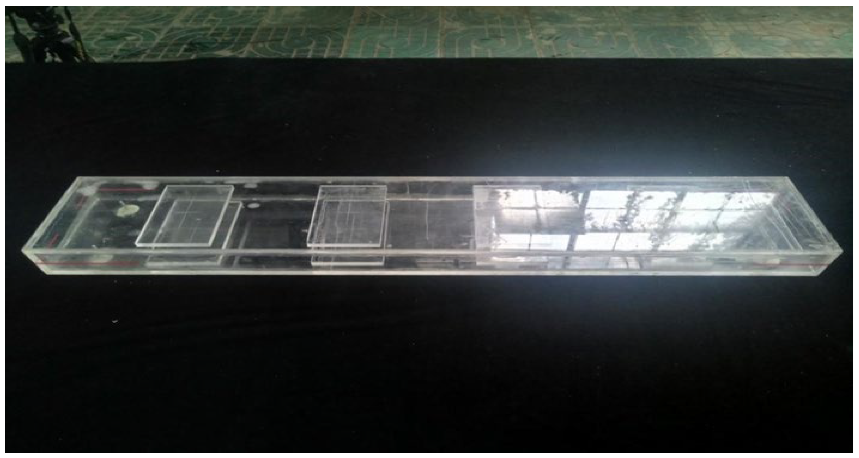
2.1. Model Design and Setup

One size of floating breakwater was chosen for this physical model experiment in order to analyze its hydrodynamic properties under two different forms of mooring: the “crossed tilt” mooring system and the “front and rear direct pull” mooring system. The model was 1:42 scale. The roll natural frequency, pitch natural frequency, and heave natural frequency of the model are 4.27 Hz, 16.7 Hz, and 35.4 Hz, respectively. Table 1 lists the model’s dimensions. The model’s geometric scale was out by 1% and within 5 mm, the center of gravity was off by 2 mm, and the mass was off by 2%. Figure 2 displays the model.
To secure the floating breakwater, we used a ∅78 AM2 anchor chain and a 125 t anchor block. The anchor chain is 72 m long, and the anchor block is 2 m underground. In the experiment, the scale of the anchor chain is 1:42. The model anchor chain is designed to be looped and to withstand only axial tension; the initial tension of the model anchor chain is similar to that of the prototype; the weight per unit length of the model anchor chain is similar to that of the prototype; and the weight of the anchor block is similar. The cable chain is shown in Figure 3.
Regarding the connection mode of the floating breakwater and anchor chain, for the “crossed tilt” mooring system and the “front and rear direct pull” mooring system, when the water level is 5.18 m, the anchor chain has no sections lying on the seabed, and when the water level is 0.0 m, the anchor chain has sections lying on the seabed. The horizontal distance between the anchor block and float tank is 1.365 m when the “crossed tilt” mooring is selected and the horizontal distance between the anchor block and float tank is 1.640 m when the “front and rear direct pull” mooring system is selected. The arrangement of the anchor chain and anchor blocks is shown in Figure 4; the red line represents the floating breakwater.
Other important scales are as follows:
Time   scale :   λ T = λ 1 0.5 = 6.48
Weight   scale :   λ W = λ 1 3 = 74 , 088
Force   ratio :   λ F = λ 1 3 = 74 , 088

2.2. Instruments and Tools for Testing

As may be seen in Figure 5a, the physical model experiments were conducted in a wind and wave flume at the Key Laboratory of the Ministry of Education for Coastal Disaster and Protection, Hohai University. The flume, which is 80 m long, 1 m wide, and 1.5 m high, can simultaneously simulate wind, waves, and currents. One end of the flume has a wave mitigation slope, and the other has a pusher-type irregular wave generator that a computer automatically controls to produce the necessary wave elements. Depending on the situation, the wave generating system can generate both regular and irregular waves with various spectral characteristics. During the flume test, the wave generator is equipped with a secondary reflection absorption device to prevent numerous reflections of the waves. The variable frequency motor and duct for the suction wind production system are mounted at the end of the flume. The wave height was measured using a capacitive wave height meter, as illustrated in Figure 5b.

2.3. Experimental Working Conditions

The physical model test was based on the water depth or topographic map near the floating breakwater and the port pool layout and berth docking schematic, and two water levels were selected according to the scale 1:42. At a high water level of 5.18 m, the anchor chain was taken to be in a non-towed state; at low water level of 0.0 m, the anchor chain was taken to be in a towed state.
Because the marina in Tingjiang Town, Mawei, Fujian Province is an inland marina that is frequently influenced by force 9 to force 12 winds due to its geographical location, wave elements of a 9th order wind wave and a 12th order wind wave were used. To investigate the impact of the ship’s moving waves, two types of wave elements were introduced into the experiment: ship’s regular wave and ship’s irregular waves. The test was carried out with irregular waves and the irregular wave spectrum was taken as the Jonswap spectrum. The effective wave height taken in the experiment was H13%. Before the wave test, the characteristic wave elements were input into the computer to generate the wave signal, and the wave generator was controlled to generate the corresponding irregular wave sequence to meet the required wave elements at the model placement. The number of irregular waves in each set of tests was greater than 200, and each set of tests was repeated several times to ensure the reliability of the test data and results.
The calibration results of different waves are shown in Table 2. The measured values and the error values are in accordance with the requirements of JTJ/T234-2001 of the Ministry of Transport’s “Wave Model Test Procedure”.
Five wave height test points were set up behind the breakwater, with the average wave height used for regular waves and the effective wave height used for irregular waves. The arrangement of the test points is shown in Figure 6; the red line represents the floating breakwater.

3. Experimental Results and Analysis

The barge-type breakwater was moored in two different ways: using the “crossed tilt” mooring system and the “front and rear direct pull” mooring system, with different water levels and wave elements. The period of the anchor chain and the anchor chain tension were measured under the two different mooring methods.
The following equation was used to define the effect of wave elimination expression:
1 H t H r × 100 %
In Equation (1), H t   is the post-dike wave height and H r   is the incident wave height.
The photos of the test situation are shown in Figure 7.

3.1. Analysis of Wave Elimination Effects

At a high-water level of 5.18 m, four different wave elements were tested under two different mooring methods, the “crossed tilt” mooring system and the “front and rear direct pull” mooring system, and the wave heights and periods were measured at five points behind the dike. The results are shown in Table 3 and Table 4. The wave dissipation effect of the breakwater is shown in Table 5 and Table 6.
The experimental findings are displayed in Table 3 and Table 5 when the barge-type breakwater uses the “crossed tilt mooring” system. While the 12th order wind wave is active, the average effect of wave elimination is 36.3%, the wave period behind the breakwater is 5.83 s, and the wave height behind the breakwater is between 1.20 m and 1.26 m. While the 9th order wind wave is active, the average effect of wave elimination is 65.2%, the wave period behind the breakwater is 4.54 s, and the wave height behind the breakwater is between 0.36 m and 0.46 m. While the ship’s irregular waves are active, the average effect of wave elimination is 69.0%, the wave period behind the breakwater is 4.54 s, and the wave height behind the breakwater is between 0.22 m and 0.29 m. While the ship’s regular waves are active, the average effect of wave elimination is 82.9%, the wave period behind the breakwater is between 2.58 s and 3.89 s, and the wave height behind the breakwater is between 0.09 m and 0.20 m.
The experimental findings are displayed in Table 4 and Table 6 when the barge-type breakwater uses the “front and rear direct pull” mooring system. The average effect of wave elimination is 32.1%, the wave period behind the breakwater is 5.83 s, and the wave height behind the breakwater is between 1.27 m and 1.34 m while the 12th order wind wave is at work. The average effect of wave elimination is 58.2%, the wave period behind the breakwater is 4.54 s, and the wave height behind the breakwater is between 0.45 m and 0.5 m while the 9th order wind wave is at work. The average effect of wave elimination is 59.5%, the wave period behind the breakwater is 4.54 s, and the wave height behind the breakwater is 0.32 m to 0.38 m when the ship’s irregular waves are at work. The average effect of wave elimination is 75.6%, the wave period behind the breakwater is between 2.81 s and 3.89 s, and the wave height behind the breakwater is 0.14 m to 0.25 m when the ship’s regular waves are at work.
The barge-type breakwater, when moored using either the “crossed tilt” or “front and rear direct pull” systems, has the best wave dissipation effect on the ship’s regular waves, according to an analysis of the test results shown in Figure 8. The wave dissipation effect of the breakwater gradually decreases as the wave element increases. The “crossed tilt” mooring system anchorage has a clearly superior effect of wave elimination over the “front and rear direct pull” mooring system.
After the end of the experiment, the second experiment was carried out. The experimental water level was 0.0 m, and the anchoring method was the “front and rear direct pull” mooring, with a section of the anchor chain lying on the seabed. Two wave conditions, the ship’s irregular wave and the 9th order wind wave, were used to measure the wave height and period at the five measuring stations behind the breakwater. The examination was performed numerous times, and the results’ average value was calculated, as seen in Table 7. The impact of the breakwater on breaking waves is depicted in Table 8. A comparison of the effect of wave elimination in front and back straight anchorage modes with and without mopping is shown in Figure 9.
The experimental findings are displayed in Table 7 and Table 8 for when the barge-type breakwater uses the “front and rear direct pull” mooring system with a section of chain lying on the seabed. The average effect of wave elimination is 43.5%, the wave period behind the breakwater is 4.54 s, and the wave height behind the breakwater is between 0.63 m and 0.67 m while the 9th order wind wave is at work. While the ship’s irregular waves are active, the average effect of wave elimination is 45.2%, the wave period behind the breakwater is 4.54 s, and the wave height behind the breakwater is between 0.45 m and 0.47 m. Analysis of Figure 9 shows that under the two different conditions of irregular waves on the ship’s line and 9th order wind wave, the effect of wave elimination of the floating breakwater with the “front and rear direct pull” mooring system with a section of chain lying on the seabed is not very significant, but its effect of wave elimination is significantly smaller than that of the “front and rear direct pull” mooring systems with no section of chain lying on the seabed.

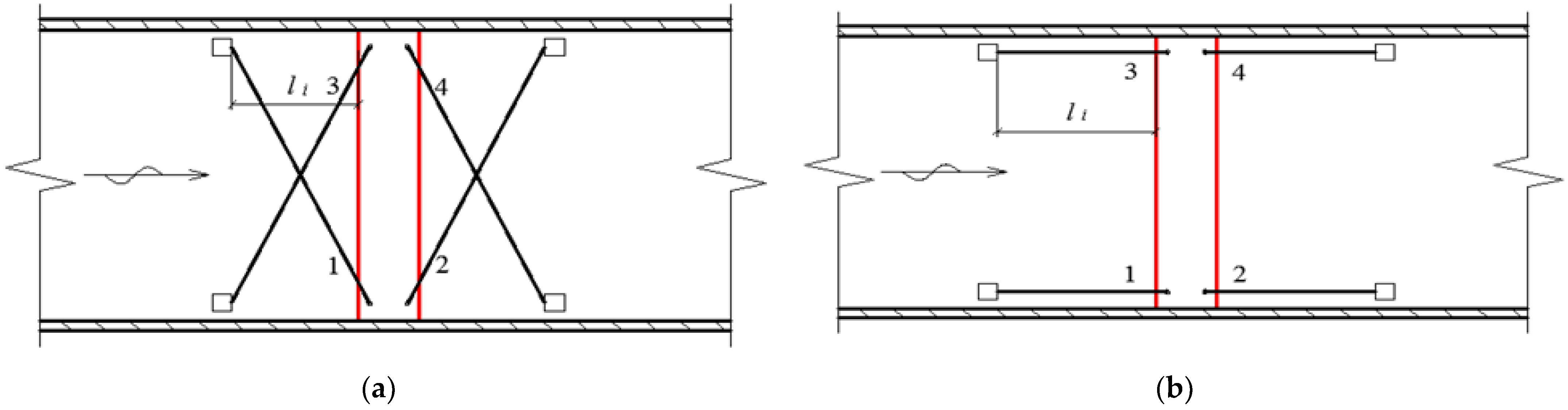
3.2. Analysis of Anchor Chain Forces

For the two different mooring methods—the “crossed tilt” mooring system and the “front and rear direct pull” mooring system, respectively—the maximum and average tension values of mooring chain 1 (wave-facing side) and mooring chain 2 (wave-backing side) were measured at a high water level of 5.18 m. Figure 8 compares the maximum and average tension values for the two mooring methods. The test results are displayed in Table 9 and Table 10.
Table 9 and Table 10 show that, for the two different mooring methods, anchor chains 1 and 2 had the highest maximum and average tension values under the 12th order wind wave, whereas the mean tension values of the anchor chains under the ship’s wave and the 9th order wind wave were smaller and relatively close in size. In addition, it was discovered that, when comparing the tension values of anchor chains 1 and 2, the tension on the wave-facing side of the anchor chain was higher than the tension on the wave-backing side.
Figure 10 and Figure 11 show that the maximum anchor chain draw increases with the wave conditions on both the wave-facing side and wave-backing side of the mooring, and that it is substantially higher in the “crossed tilt” mooring than in the “front and rear direct pull” mooring. Nonetheless, there are not many differences in the typical mooring chain pull between the two mooring styles. The mooring chain force is marginally stronger on the waveward side than on the backward side, though.
Using the “front and rear direct pull” mooring system with a section of chain lying on the seabed, the maximum tension values and average values of anchor chain 1 (wave-facing side) and anchor chain 2 (wave-backing side) were measured at a water level of 0.00 m under various wave conditions. The tests were repeated several times, and the results were averaged. Table 11 illustrates this. The maximum and average pulling forces applied to the mooring chains under the front and aft direct pulling mooring techniques are compared in Figure 11 and Figure 12.
The experimental results in Table 11 demonstrate that, under the influence of a 9th order wind wave, the maximum tension value of anchor chain 1 exceeds the ship’s irregular wave, whereas the maximum and average tension values of anchor chain 2 are very similar to one another. The maximum tension of the anchor chain on the waveward side was significantly greater than the maximum tension of the anchor chain on the backward side, and the average tension values of both were relatively close to one another, according to a comparison of the tension values of anchor chains 1 and 2.
The test results in Figure 12 and Figure 13 show the anchor chain tension in two different states of the barge-type breakwater under the fore and aft straight pull mooring method. After comparative analysis, the results show that the anchor chain tension in the section lying on the seabed is significantly greater than when no section is lying on the seabed.

4. Results

The yacht project at Tingjiang Town, Mawei, Fujian is used as an example in this thesis to discuss the hydrodynamic properties of the barge-type breakwater under two forms of mooring: the “crossed tilt” mooring and the “front and rear direct pull” mooring. The specific findings of the study are as follows.
  • Under the influence of the ship’s waves (regular waves, irregular waves), a 9th order wind wave, and a 12th order wind wave, the wave elimination effect of the barge-type breakwater gradually decreases with the increase of wave elements; the effect of wave elimination of the barge-type breakwater on the ship’s waves is the best, reaching a maximum of 68.3% (ship’s irregular waves), while the maximum tension value of the anchor chain gradually increases with the increase of wave elements, reaching a maximum of 3914.75 kN (12th order wind wave).
  • The maximum anchor chain pull under the “crossed tilt” mooring is significantly better than that under the “front and rear direct pull” mooring; the average anchor chain pull does not differ significantly between the two mooring methods, and the anchor chain force on the wave-facing side is slightly greater than that on the other side.
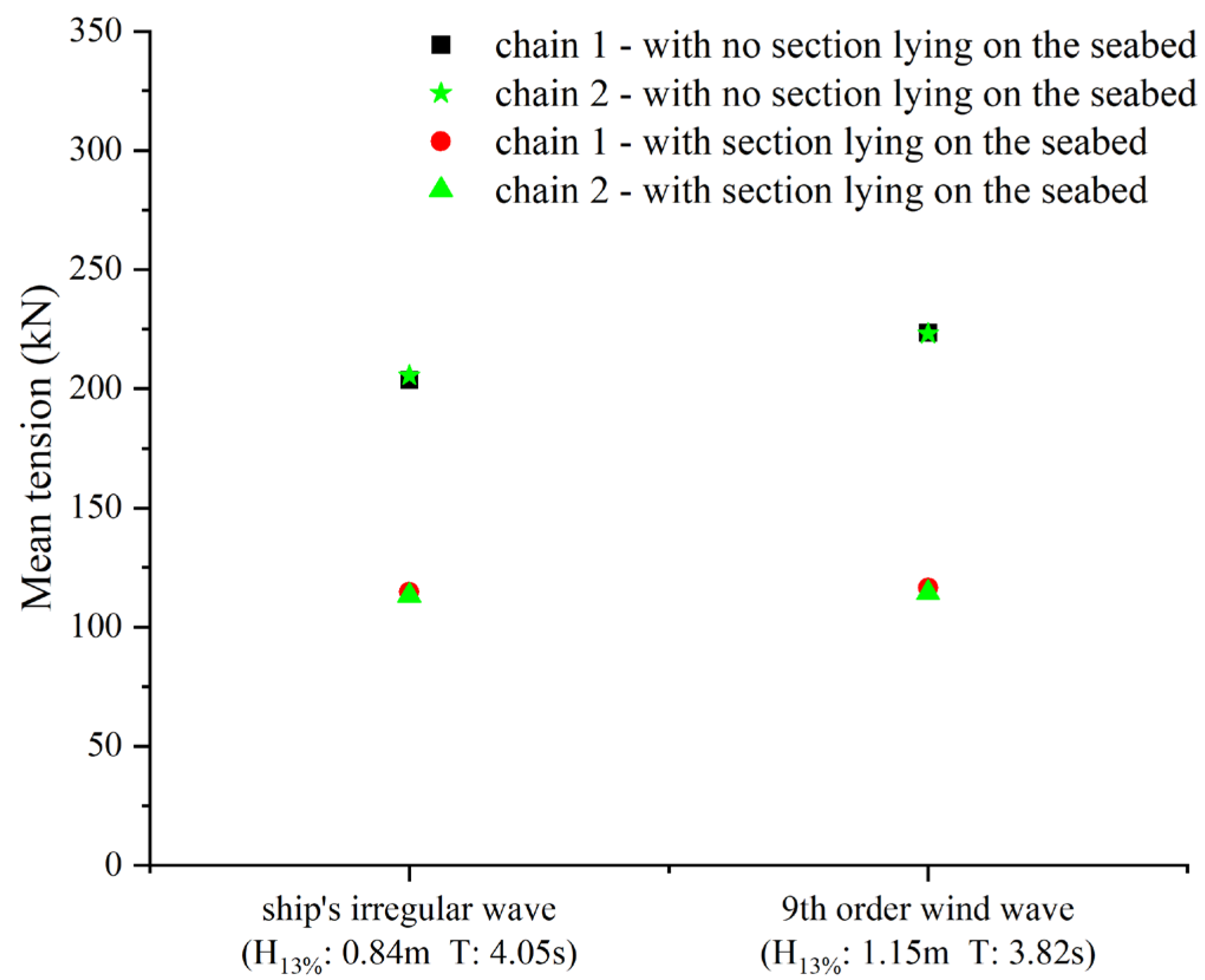
  • The wave elimination effect of the barge-type breakwater under the condition of anchor chain not dragging (the chain with no section lying on the seabed) is obviously better than that under the condition of mopping (the chain with a section lying on the seabed), but the tension of the anchor chain under the condition of non-mopping (the chain with no section lying on the seabed) is obviously greater than that under the condition of mopping (the chain with a section lying on the seabed).
Based on the results of the two-dimensional physical modeling of the barge breakwater, as well as the influence of the mooring method on the wave dissipation effect and the force on the anchor chain, it is recommended that construction workers use the “crossed tilt” mooring method during the construction process to achieve a better wave dissipation effect and to improve its ability to withstand large waves and bad weather. It is also recommended that care be taken to regulate the forces on the anchor chain on the wave-facing side to ensure the breakwater’s stability. Given that the wave dissipation effect and anchor chain forces are significantly better in the chain without a section lying on the seabed than in the chain with a section lying on the seabed, it is recommended that the anchor chain be kept as untowed as possible during the construction process.
The sectional model was used in this study to address the problems encountered during the project. The experimental study considers only the forward wave, which has a large influence on the port, and fails to consider the influence of different wave directions on the floating breakwater. The measurement of wave height behind the breakwater did not account for the influence of breakwater connection and wave diffraction. Furthermore, the force of the interaction between the breakwater connection motion states was not taken into consideration in the measurement of anchor chain tension. As a result, the impact of the aforementioned elements can be investigated further in future research.

Author Contributions

Conceptualization, X.C.; methodology, X.C.; software, S.L.; validation, G.W.; formal analysis, X.C.; investigation, S.L.; resources, X.C.; data curation, S.L.; writing—original draft preparation, S.L.; writing—review and editing, X.C.; visualization, G.W.; supervision, G.W.; project administration, X.C.; funding acquisition, X.C. All authors have read and agreed to the published version of the manuscript.

Funding

This research was funded by the Postgraduate Research & Practice Innovation Program of Jiangsu Ocean University.

Institutional Review Board Statement

Not applicable.

Informed Consent Statement

Not applicable.

Data Availability Statement

Not applicable.

Conflicts of Interest

The authors declare no conflict of interest.

References

  1. Shen, Y.-S.; Zhou, Y.; Pan, J.-N. Research progress and application of floating breakwater. Hydro-Sci. Eng. 2016, 5, 124–132. [Google Scholar]
  2. Fu, R.-X.; Mao, J.-Z.; Yin, W.-J.; Xu, Y.-B. Research status of floating breakwater structure. Port Waterw. Eng. 2016, 6, 61–66. [Google Scholar]
  3. Dong, H. Study on Hydrodynamic Characteristics of Pontoon-Plates TypeFloating Breakwaters. Ph.D. Thesis, Dalian University of Technology, Dalian, China, 2009. [Google Scholar]
  4. Lianyungang Built China’s First Floating Breakwater, Turning the Sea into a “Good Field”. Available online: https://news.sina.com.cn/c/2002-09-03/1315704178.html (accessed on 17 April 2023).
  5. Sutko, A. Floating Breakwaters—A Wave Tank study. J. Pet. Technol. 1975, 27, 269–273. [Google Scholar] [CrossRef]
  6. McCartney, B. Floating Breakwater Design. J. Waterw. Port Coast. Ocean. Eng. 1985, 111, 304–318. [Google Scholar] [CrossRef]
  7. Wang, Y.; Wang, G. Research progress and engineering applications of near-shore floating breakwater structures. Shipbuild. China 2002, 10, 314–321. [Google Scholar]
  8. Headland, J.R.; Vallianos, L. Dynamic Analysis of Floating Breakwater Mooring Systems. In Coastal Engineering 1990; American Society of Civil Engineers: Delft, The Netherlands, 1991; pp. 1320–1333. [Google Scholar] [CrossRef]
  9. He, C.; Wang, D.; Feng, W. Experimental study on wave attenuation of rectangular-pontoon floating breakwater. Port Waterw. Eng. 2014, 1, 14–18. [Google Scholar]
  10. Chen, C.; Chen, X.Q.; Yang, O. Wave suppression performance of wing plate floating breakwater. Port Waterw. Eng. 2022, 9, 8–14. [Google Scholar]
  11. Ji, C.-Y.; Guo, Y.-C.; Cui, J.; Yuan, Z.-M.; Ma, X.-J. 3D experimental study on a cylindrical floating breakwater system. Ocean Eng. 2016, 125, 38–50. [Google Scholar] [CrossRef]
  12. Cheng, X.; Liu, C.; Zhang, Q.; He, M.; Gao, X. Numerical Study on the Hydrodynamic Characteristics of a Double-Row Floating Breakwater Composed of a Pontoon and an Airbag. J. Mar. Sci. Eng. 2021, 9, 983. [Google Scholar] [CrossRef]
  13. Mao, X.; Guo, J.; Ji, C. Wave load analysis of floating breakwater with arc-shaped layout. Ship Sci. Technol. 2022, 44, 92–99. [Google Scholar]
  14. Dong, H.; Zuo, Z.G.; Xiang, R.-X. A new type of steel structure’s floating breakwater structure. Port Waterw. Eng. 2022, 1, 73–76. [Google Scholar]
  15. Wan, Y. Experimental study on hydrodynamic characteristics of floating breakwater with double cylinders and plates. J. Xiamen Univ. Technol. 2021, 29, 68–72. [Google Scholar]
  16. Ge, J.; Ji, C.; Guo, J. Hydrodynamic response analysis of floating breakwater with arc arrangement. Ship Eng. 2021, 43, 152–157. [Google Scholar]
  17. Li, S. Experimental study of wave dissipation characteristics of open floating box breakwaters. J. Waterw. Harb. 2016, 37, 115–120. [Google Scholar]
  18. Sannasiraj, S.; Sundar, V.; Sundaravadivelu, R. Mooring forces and motion responses of pontoon-type floating breakwaters. Ocean Eng. 1998, 25, 27–48. [Google Scholar] [CrossRef]
  19. Dong, H.; Wang, Y.; Chen, Y. Experimental study on the wave dissipation performance of floating breakwaters with different anchoring methods. Ocean. Eng. Branch Chin. Soc. Oceanogr. 2017, 189, 264–268. [Google Scholar]
  20. Ji, C.; Meng, X.; Guo, J. Research on slamming load and motion response of floating breakwater under different anchorage modes. Ship Sci. Technol. 2021, 43, 95–99. [Google Scholar]
  21. Liang, J.-M.; Liu, Y.; Chen, Y.-K.; Li, A.-J. Experimental study on hydrodynamic characteristics of the box-type floating breakwater with different mooring configurations. Ocean Eng. 2022, 254, 111296. [Google Scholar] [CrossRef]
Figure 1. (a) Location map; (b) Plan of harbor pool.
Jmse 11 01016 g001
Figure 2. Model of a barge-type breakwater.
Jmse 11 01016 g002
Figure 3. Anchor chain used in the experiment.
Jmse 11 01016 g003
Figure 4. (a) ”Crossed tilt” mooring; (b) “Front and rear direct pull” mooring.
Jmse 11 01016 g004
Figure 5. (a) Wind and wave flume; (b) Capacitive wave height meter.
Jmse 11 01016 g005
Figure 6. Wave height measurement points behind the breakwater.
Jmse 11 01016 g006
Figure 7. (a) “Crossed tilt” mooring; (b) “Front and rear direct pull” mooring.
Jmse 11 01016 g007
Figure 8. Comparison of the effect of wave elimination in the two mooring conditions.
Jmse 11 01016 g008
Figure 9. Comparison of the effect of wave elimination of the “front and rear direct pull” mooring in two different states.
Jmse 11 01016 g009
Figure 10. Comparison of maximum tension in the two different mooring modes.
Jmse 11 01016 g010
Figure 11. Comparison of mean tension under two different anchoring modes.
Jmse 11 01016 g011
Figure 12. Comparison of the maximum tension in two different states with the “front and rear direct pull” mooring with a section of chain lying on the seabed.
Jmse 11 01016 g012
Figure 13. Comparison of the mean tension in two different states with the “front and rear direct pull” mooring with a section of chain lying on the seabed.
Jmse 11 01016 g013
Table 1. Barge model parameters and mooring methods.
Length
Li (m)
Width
Bi (m)
Molded Depth Hi (m)Draft hi (m)Mooring Systems
Prototype value42.0008.0003.0001.500“crossed tilt”
“front and rear direct pull”
Experimental value1.0000.1900.0710.036
Table 2. The calibration results of different waves.
Wave TypePrototype ValueTest ValueError
Water Level (m)Water Depth (m)Wave Height (m)Period T (s)Water Depth (m)Wave Height (m)Period T (s)Wave Height (%)Period T (%)
9th order wind wave5.1815.181.123.740.361.153.822.702.70
0.0010.001.123.740.241.153.822.702.70
12th order wind wave5.1815.181.924.900.361.934.870.500.50
Ship’s regular wave5.1815.180.824.000.360.824.020.000.00
0.0010.000.824.000.240.824.020.000.00
Ship’s irregular wave5.1815.180.824.000.360.844.052.402.40
0.0010.000.824.000.240.844.052.402.40
Table 3. Wave height and period behind the breakwater (“crossed tilt”).
Wave TypeIncident WaveMeasurement Points
12345
Ship’s regular wave H ¯   (m)0.820.130.090.200.150.12
Ship’s irregular wave H13% (m)0.840.290.280.260.250.22
9th order wind wave H13% (m)1.150.460.400.390.390.36
12th order wind wave H13% (m)1.931.261.261.251.201.20
Ship’s regular wave T (s)4.022.853.653.493.893.67
Ship’s irregular wave T (s)4.054.544.544.544.544.54
9th order wind wave T (s)3.824.544.544.544.544.54
12th order wind wave T (s)4.875.835.835.835.835.83
Table 4. Wave height and period behind the breakwater (“front and rear direct pull”).
Wave TypeIncident WaveMeasurement Points
12345
Ship’s regular wave H ¯ (m)0.820.20.250.230.180.14
Ship’s irregular wave H13% (m)0.840.380.330.330.330.32
9th order wind wave H13% (m)1.150.50.470.480.480.45
12th order wind wave H13% (m)1.931.341.341.311.271.27
Ship’s regular wave T (s)4.023.022.813.893.893.24
Ship’s irregular wave T (s)4.054.544.544.544.544.54
9th order wind wave T (s)3.824.544.544.544.544.54
12th order wind wave T (s)4.875.835.835.835.835.83
Table 5. Effect of wave elimination (“crossed tilt”).
Wave Type H r   ( m ) H t   ( m ) Effect of Wave Elimination
Ship’s regular wave H ¯ (m)0.820.1482.9%
Ship’s irregular wave H13% (m)0.840.2669.0%
9th order wind wave H13% (m)1.150.4065.2%
12th order wind wave H13% (m)1.931.2336.3%
Table 6. Effect of wave elimination (“front and rear direct pull”).
Wave Type H r   ( m ) H t   ( m ) Effect of Wave Elimination
Ship’s regular wave H ¯ (m)0.820.2075.6%
Ship’s irregular wave H13% (m)0.840.3459.5%
9th order wind wave H13% (m)1.150.4858.2%
12th order wind wave H13% (m)1.931.3132.1%
Table 7. Wave height and period behind the breakwater (with a section of chain lying on the seabed).
Wave TypeIncident WaveMeasurement Points
12345
Ship’s irregular wave H13% (m)0.840.450.470.460.460.45
9th order wind wave H13% (m)1.150.630.670.670.660.63
Ship’s irregular wave T (s)4.054.544.544.544.544.54
9th order wind wave T (s)3.824.544.544.544.544.54
Table 8. Effect of wave elimination (with a section of chain lying on the seabed).
Wave Type H r   ( m ) H t   ( m ) Effect of Wave Elimination
Ship’s irregular wave0.840.4645.2%
9th order wind wave1.150.6543.5%
Table 9. Maximum tension and average tension of the “crossed tilt”.
Wave TypeChain 1
Initial
Tension
Chain 1
Maximum
Tension
Chain 1
Mean
Tension
Chain 2
Initial
Tension
Chain 2
Maximum
Tension
Chain 2
Mean
Tension
Ship’s regular wave156.72 kN781.88 kN205.37 kN165.55 kN333.76 kN202.27 kN
Ship’s irregular wave156.72 kN1163.69 kN188.61 kN165.55 kN546.92 kN188.50 kN
9th order wind wave156.72 kN2318.25 kN209.15 kN165.55 kN836.74 kN201.89 kN
12th order wind wave156.72 kN3914.75 kN266.24 kN165.55 kN1811.53 kN254.48 kN
Table 10. Maximum tension and average tension of the “front and rear direct pull”.
Wave TypeChain 1
Initial
Tension
Chain 1
Maximum
Tension
Chain 1
Mean
Tension
Chain 2
Initial
Tension
Chain 2
Maximum
Tension
Chain 2
Mean
Tension
Ship’s regular wave170.31 kN918.29 kN232.28 kN175.38 kN472.05 kN230.59 kN
Ship’s irregular wave170.31 kN1009.35 kN203.70 kN175.38 kN481.89 kN205.53 kN
9th order wind wave170.31 kN1788.58 kN223.46 kN175.38 kN837.11 kN223.14 kN
12th order wind wave170.31 kN3507.23 kN267.97 kN175.38 kN1502.14 kN263.90 kN
Table 11. Maximum tension and average tension of the “front and rear direct pull” mooring with a section of chain lying on the seabed.
Wave TypeChain 1
Initial
Tension
Chain 1
Maximum
Tension
Chain 1
Mean
Tension
Chain 2
Initial
Tension
Chain 2
Maximum
Tension
Chain 2
Mean
Tension
Ship’s irregular wave101.00 kN225.15 kN114.75 kN112.87 kN128.86 kN113.22 kN
9th order wind wave101.00 kN468.41 kN116.46 kN112.87 kN136.81 kN114.40 kN
Disclaimer/Publisher’s Note: The statements, opinions and data contained in all publications are solely those of the individual author(s) and contributor(s) and not of MDPI and/or the editor(s). MDPI and/or the editor(s) disclaim responsibility for any injury to people or property resulting from any ideas, methods, instructions or products referred to in the content.

