Abstract
In the past few years, underwater wireless optical communication (UWOC) has become a promising wireless communication technology in the underwater environment. Aiming at the problem formulation of sub-channel correlation enhancement occurring due to the joint impact of underwater link misalignment and turbulence in the process of optical signal transmission in an underwater optical massive multiple-input multiple-output (MIMO) system, we propose an adaptive diversity approach depending on partition space time block code (STBC). STBC technology is used to reduce the random fading of optical signals caused by turbulence. At the same time, the channel correlation occurring due to channel misalignment is effectively alleviated by adaptive processing. The adaptive diversity algorithm based on segmented STBC effectively improves the reliability and decrease complexity of underwater optical Massive MIMO communication systems. It determines the particular link misalignment degree by the channel gain matrix obtained from the channel estimation and selects different combinations of detectors according to the degree of misalignment to obtain the maximum gain of the received signal combination. Compared with the chunking scheme, simulation and result shows that the adaptive diversity algorithm improves the tolerance of the system to the link misalignment error from 30 mm to 60 mm under the same condition number of channel gain matrix, and it can still demodulate the source signal directly without requiring detection algorithm in case of a large error in the link misalignment.
1. Introduction
In the past few years, with the rapidly expanding of the diminution of resources, people have shown a remarkable attention to the research of ocean monitoring, observation and exploration systems. With the expansion of marine security, scientific research activities, environmental monitoring, exploration, and other application activities in the underwater environment, reliable, robust, secure, high-speed wireless communication technology is urgently needed. Currently, underwater acoustic is the most extensively utilized underwater wireless communication technology because of its key potentials of moderate tolerance to water turbulence and long transmission distance [1]. Nevertheless, the data rate of underwater acoustic communication is severely restricted to kbps. Moreover, acoustic signals propagate through water at a speed of 1480 m per second. Consequently, they suffer from long propagation delays [2]. Furthermore, radio frequency (RF) [3] can significantly reduce the latency. Nevertheless, RF waves are prone to excessive propagation loss in underwater environment. Therefore, underwater RF systems typically have a limited operating distance up to 1 m [4]. Similarly, blue and green light with a wavelength between 450 nm and 550 nm is relatively attenuated by seawater. Thus, blue and green light band-enabled underwater wireless optical communication (UWOC) technology has the practical benefits and distinct potential of low delay and high bandwidth, which can be considered as a promising alternative to underwater acoustic communication to achieve high-rate and short-distance underwater communication [5].
UWOC has attained substantial interest worldwide from both academia and industrial communities due to its key feature of attaining high data rates over short distances [6,7]. In the previous few years, breakthrough novelties in UWOC have been witnessed through optical sources with higher transmission efficiency and power levels, higher sensitive photodetectors, or advanced coding schemes [8]. Laser-diodes (LD) [9,10] and light-emitting diodes (LEDs) [11,12] have been utilized for various UWOC applications. Contrasted with LD, LED offers the unique benefits of long service life, high power efficiency, and low cost, but LED’s narrow modulation bandwidth is the main limitation to developing high data-rate communications. To effectively secure high data-rate communications, the Massive MIMO technology in the RF-aided communication system is implemented in underwater wireless communication systems [13,14,15].
However, the achievable rate of Massive MIMO is severely restricted by the channel correlation [16,17], and the crucial issue of channel correlation is more critical because of the dominant LOS component [18]. Consequently, even 16 × 16 MIMO and 36 × 36 MIMO are considered Massive MIMO because they indicate high channel correlation, leading towards a very high condition number of the channel gain matrix [19]. Similarly, high spatial channel correlation causes a higher inter-channel interference (ICI) in underwater optical Massive MIMO systems. Channel correlation can be effectively reduced by spatial modulation and modulation of transmitter power [20]. In such systems, spatial diversity is achieved by adopting imaging structure at the receiver. In general, hemispherical lenses [21] and fisheye lenses [22] are used to support a wide-open field of view (FoV) while splitting beams, decreasing interference between various LEDs and maximizing optical gain.
In the real-time short distance underwater optical communication environment, the relative mobility occurring due to ocean currents is highly complicated for attaining precise alignment. Link misalignment will allow the detector to get interference signals from adjacent LEDs, consequently leading to enhanced channel correlation. Adjusting the size of the receiving aperture or the order of the multiple quadrature amplitude modulation (M-QAM) can effectively reduce the influence of interference caused by pointing error [23]. To overcome the challenge of aggravated interference between spot arrays, the approach of maximum ratio combining using successive interference cancellation (MRC-SIC) was considered [24]. Nevertheless, the approach can only be implemented in such conditions with a small degree of link misalignment.
Additionally, random fading and high power loss occurring due to turbulence, scattering, absorption and other prominent elements are major concerns restricting the reliability performance improvement and communication distance of the UOWC system. There have been studies on turbulent channel models in free space optical communication (FSOC). The underwater turbulence channel model has some similarity with atmospheric turbulence [25,26]. To mitigate the effect of turbulence on UOWC, some approaches such as spatial diversity techniques can be utilized [27]. STBC is usually considered to overcome the random fading occurring due to turbulence in UWOC systems [28]. This technique is also widely used in MIMO-UWOC systems. The STBC technique makes the coded symbols orthogonal in space and time, simplifies the decoding process of the received symbols and reduces the complexity of the symbol decoding [29]. The combination of STBC technique and equal gain combining (EGC) technique [30] can further decrease the complexity of the receiver. In [31], an improved order successive interference cancellation (I-OSIC) algorithm based on the partitioned STBC technique is proposed. However, with a large degree of channel misalignment, if the detectors at the receiver side are combined in a group of four chunks, it rather enhances the interference between the signals. Moreover, using the detection algorithm at the receiver side increases the complexity of signal detection.
In this paper, a partition STBC adaptive diversity algorithm is proposed for the joint effect caused by link misalignment and turbulence. The signal can be effectively detected at the receiver side using a low-complexity detection algorithm. The adaptive diversity algorithm depending on partition STBC reduces the influence of random attenuation of optical signal occurring due to turbulence on system reliability by sacrificing part of the communication links, and also reduces the influence of aggravation of inter-channel interference caused by link misalignment. Our main contributions are summarized in the following:
- The imaging spot displacement phenomenon caused by the combined effect of turbulence and link misalignment can cause interference to adjacent detectors in a Massive MIMO system. To address this issue, we propose a signal adaptive diversity system in a Massive MIMO system, in which the signals received by different detectors are combined according to the size of the interference.
- Based on the optical Massive MIMO adaptive diversity system, we propose an evaluation model and a method to judge the degree of link misalignment. The optimal merging scheme can be found by this method.
- Further, we propose an adaptive diversity algorithm in the adaptive diversity system and the optimal merging model, in which the receiver adopts EGC combining technology to combine the signals received by different detectors according to the size of the interference. It will resist the effects of the joint effects of turbulence and link misalignment.
The rest of this paper is organized as follows. In Section 2, we provide a MIMO-ACO-OFDM based underwater imaging optical system and underwater imaging optical MIMO channel model. The adaptive diversity algorithm model is presented in Section 3. The simulation result analysis is presented in Section 4. Our conclusions are presented in Section 5.
2. System Model
In this paper, an underwater 16 × 16 MIMO system is established, where the transmitter contains an array of 16 LED optical sources, and the receiver is based on 16 rectangular detectors as well as a lens group. The modulated signal is transformed to an optical signal through an LED transmitter, and it is passed through the underwater channel; the light beam between different LEDs is separated through the lens group at the receiver to reduce the interference between different beams. As shown in Figure 1, the rectangular array light source is located at the origin and parallel to the plane of the coordinate system. Under the condition of alignment between the transmitter and receiver, the central axis of the transmitter and receiver is parallel to the x-axis, and the communication distance is 4 m.
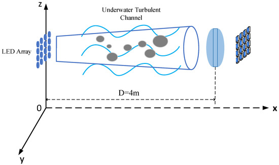
Figure 1.
Underwater optical imaging communication system model.
2.1. MIMO-ACO-OFDM Based Underwater Imaging Optical System
The 16 LEDs at the transmitter of the system are categorized into four groups of optical sources, and every group contains four LEDs. The STBC technology is used for encoding the data transmitted through each group of four LEDs, and four different signals are transmitted through four groups of optical sources, respectively.
The block diagram shown in Figure 2 represents the system combining orthogonal frequency division multiplexing (OFDM) modulation and STBC technology. As illustrated in Figure 2, the transmitter of the system is based on LEDs and the receiver detectors. The binary bit data stream is constrained by quadrature amplitude modulation (QAM) mapping. These QAM symbols are encoded by STBC technology and then asymmetric clipped OFDM (ACO-OFDM) is used for modulation to attain OFDM symbols. At the end, they are transformed into an optical signal using LED after performing a clipping process. When the optical signal arrives at the receiver, four large optical spots are attained by imaging using an imaging lens. The multiple detectors covered by each light spot are combined using EGC technology, and the combined data is obtained after demodulation by ACO-OFDM. Finally, through STBC decoding and QAM demodulation, the received data stream is obtained.

Figure 2.
Block diagram of MIMO ACO-OFDM STBC system.
2.2. Underwater Imaging Optical MIMO Channel Model
Seawater includes different chlorophyll, minerals, inorganic salts, etc. These particles pose an absorption impact on photon energy and an impact on the direction of photon mobility. The combined effect of these two indicates the total attenuation coefficient for underwater optical signal transmission. We consider clear ocean water for the simulation task, where we consider as the total attenuation coefficient of visible light. The channel DC gain can be measured by the given numerical expression [32]:
where represents the transmitter efficiency and represents the conversion efficiency of the receiving detector. The equivalent receiving area of the detector is , and the diameter of the transmitter collimating lens is , while the diameter of the receiver lens is , is the Lambertian radiation order, , the half-power emission angle of the LED is , LED emission angle is , represents the angle of incidence of the detector, and is the communication distance. The channel gain matrix is achieved through the calculated channel DC gain, where .
The channel gain matrix is achieved by the DC gain coefficient, and we can express the receiver’s signal vector as:
where is a channel gain matrix, is a signal vector of transmitter, denotes Gaussian white noise with variance of and a 0 mean.
2.3. Underwater Link Misalignment and Turbulence Channel Model
When the optical beam is transmitted through underwater media, the underwater turbulence will introduce random fluctuation in the optical signal’s amplitude while signal propagation [33]:
where indicates the fading coefficient caused by turbulence, which obeys an exponential normal distribution, represented as , and represent the mean and variance of the normal-distribution. The article adopts standard normal distribution with a mean and a variance of 0 and 1, respectively. In general, the scintillation index is considered to quantify the turbulence impact, which can be expressed as:
In addition to the impact of turbulence, the UWOC system also suffers from the misalignment between transmitter and receiver. The link misalignment error caused by the misalignment of the receiving and starting terminals can be determined by the Rayleigh distribution PDF [34]:
where link misalignment error is expressed as , and represents the variance of the link misalignment error. According to the maximum link misalignment error defined in the article, .
Figure 3 shows the image spot distribution representation of the receiver under alignment and misalignment scenarios. The relative offset generated by the transceiver in the plane is divided into two parts of parallel x-axis and y-axis through the geometric decomposition technique. As shown in Figure 3b, the receiving detection will obtain various optical spots at the same time due to link misalignment, which will lead to increased interference between the MIMO system sub-channels.

Figure 3.
Image spot distribution diagram at the receiver. (a) Transceiver alignment. (b) Transceiver misalignment.
In order to better describe the image spot distribution under transceiver alignment and misalignment scenarios, we made the following assumptions: (1) The diameter of the imaging spot is equal to the length of the detector side, and the diameter is , and the imaging spot covers the detector when the transceiver is aligned; (2) The light intensity within the image spot is uniformly distributed; (3) There is a small gap between various detectors. When the link misalignment occurs, the image spot will illuminate adjacent detectors, causing interference.
By tracking each light path of the LED source through ZEMAX software, we can obtain the light spot distribution at the receiver. Because the simulated system is a 16×16 MIMO system with a larger scale than the conventional MIMO system, the channels’ correlation is higher and the interference between imaging spots is larger. In this study, the aspherical imaging lens group is used as the receiver imaging lens [29]. The impact of imaging lens spherical aberration can be significantly reduced by the aspherical lens, and various lenses can be used to efficiently separate the interference between the image spots of various LEDs. Table 1 represents the simulation parameters of the optical path.

Table 1.
ZEMAX optical simulation parameters for Massive MIMO.
Figure 4 represents the imaging light spot distribution at the receiving end. Each spot is separated with a spacing of about 3.2 mm, and the beams between different LEDs are effectively separated by the imaging lens groups.
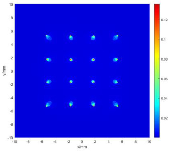
Figure 4.
The pattern of image spot at the receiver.
Figure 5 represents the relation between the condition number of channel gain matrix and the offset due to the relative offset of the transmitter and receiver in the plane, which is expressed by the condition number of channel gain matrix [25]. The condition number of channel gain matrix increases when the relative offset of the transmitter and receiver is increased. When the condition number of channel gain matrix is small, the interference between the receiver signals is also small and can be achieved through direct demodulation. By increasing the degree of link misalignment, we notice an increase in the condition number of channel gain matrix; meanwhile, the interference becomes high, and direct demodulation of the signals cannot be performed.
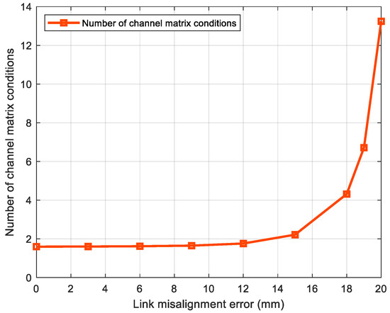
Figure 5.
The link misalignment error versus condition number of H.
The optical beams from various LEDs are separated by using the imaging lens at the receiver side. However, when the link misalignment appears, the interference between different LED beams usually becomes more and more severe because of spot migration, in which the diagonal elements are much larger than the non-diagonal elements of channel matrix. So, the channel gain matrix can be expressed as follows:
where indicates the image spot size of the LED on the detector. and refer to the number of LEDs at the transmitting end and total number of detectors at the receiver, respectively.
Considering the combined impact of link misalignment and turbulence, we can substitute the turbulence random attenuation coefficient into Equation (6), and the channel gain matrix can be obtained as:
3. Adaptive Diversity Algorithm Model
In this study, the block diagram of the adaptive diversity system is shown in Figure 6. At the transmitter side, the data are processed with block STBC coding and ACO-OFDM modulation. At the receiving end, adaptive diversity processing is applied to the received signal, and finally the signal is demodulated and decoded to restore the data. We use the Alamouti STBC algorithm to decrease the influence of turbulence on reliability of the system. To further decrease the complexity of the system receiver, EGC technology is used for the signal merging process at the receiver [27].

Figure 6.
Adaptive diversity system block diagram.
The traditional STBC decoding is carried out through the following formula:
where is the decoded signal, is the received signal of the , and is the channel gain coefficient of the signal.
EGC technology is adopted for combining the received signal, that is, STBC is simplified into STBC, and the decoding process is simplified as follows:
where represents the received signal after combining, and is the combined channel gain coefficient.
Under the condition of the same signal power at the transmitting end, STBC coding technology is adopted for some antennas of the large-scale MIMO system by block diversity algorithm. The orthogonal property of the STBC code symbol in time and space is used to reduce the influence of underwater turbulence on the system. The STBC-EGC technique effectively reduces the complexity and improves the system reliability and communication capacity using block processing. In this paper, the influence brought by turbulence is reduced by partition STBC.
As shown in Figure 3a, there are 16 LEDs at the transmitter side. Categorize 16 LEDs into four groups of light sources, and each group of optical sources based on four LEDs. The STBC technique is used to encode the data transmitted by the four LEDs in each group, and the four groups of optical sources respectively transmit four different signals to form a Massive MIMO communication system. Therefore, the communication links are divided into four parts; each part transmits different communication data, and the communication links in each part adopt STBC-EGC technology. However, the light spot obtained by imaging will be offset along with the relative offset error of the transceiver. For the large degree of link misalignment, when the light spot is completely distributed on the adjacent detectors, it is difficult to select and combine the received signal of the receiver.
Different relative misalignment directions of the transceiver will lead to the offset direction of the receiver’s imaging spot. The detector will be interfered with different spots, and the channel increment matrix will also change. The relative offset direction of the receiving and sending terminal is estimated through the channel gain matrix. In this paper, the channel gain coefficient is estimated by least square (LS) channel estimation, and the estimated channel gain matrix is used to trace the direction of spot migration. The tracking criterion is shown as follows:
where is the channel gain of the row in channel gain matrix , and is the mean of channel gain of row . When is established, the link misalignment is serious and the receiver detector needs to be selected and merged. The channel gain matrix is obtained by channel estimation and the LED combination set of transmitter diversity is obtained by using the adaptive diversity algorithm proposed in this paper. The adaptive diversity algorithm is expressed as follows (Algorithms 1):
| Algorithms 1: Adaptive diversity algorithm. |
| Input: Channel estimation obtained channel gain matrix . Output: Diversity Combine index set . Initialization: Link misalignment threshold , Diversity Combine index set , index set , , , , . Loop Steps 1–3: Steps 1: Find the footer corresponding to the element in row of the channel gain matrix of the channel gain matrix whose misalignment threshold satisfies , which is . Steps 2: Updating the index set . Steps 3: If , Break; Else, Continue. Loop Steps 4–6: Steps 4: Updating the index set . Steps 5: If ; Else, Continue. Steps 6: If , Break; Else, Continue. |
So, according to the adaptive diversity scheme, the imaging spot distribution under different degrees of channel misalignment is shown in Figure 7. By implementing diversity technology in the Massive MIMO system blocks, the imaging under the similar diversity combination is joined into a large spot. Figure 7a represents the spot distribution under a small degree of link misalignment. Because of the block diversity technique used, the correlation between same diversity combination sub-channels does not need to be considered; only the correlation between different diversity blocks should be taken into account. In this way, the dimension of the channel gain matrix of Massive MIMO system is decreased along with reduction in the correlation between sub-channels. As shown in Figure 7b, due to the increase of the link misalignment degree under large link misalignment, the block diversity technology of the receiver detector cannot bring signal merging gain but strengthens the interference between signals. Therefore, it is necessary to adopt different diversity schemes for different link misalignment degrees.

Figure 7.
Spot distribution under different link misalignments. (a) Small degree of link misalignment. (b) Large degree of link misalignment.
In addition, we can take a single offset direction as an example as shown in Figure 7b. For the interference caused by link misalignment, only the spot interference on the detectors numbered 5, 7, 13 and 15 (the number is as shown in Figure 3) should be considered, and this single-direction scene is applied to other offset directions. For the complex offset directions, the interference on multiple rows of detectors should be considered. Since the receiver adopts EGC combining technology, the signals received by different detectors need to be combined according to the size of the interference.
4. Simulation Results Analysis
In underwater optical Massive MIMO systems, the condition number of the channel gain matrix increases as the relative offset between the transmitter and receiver increases. By categorizing the underwater optical Massive MIMO system into blocks and considering diversity technique, the correlation of channel gain matrix is significantly reduced as well as the dimension of the channel gain matrix [32].
The adaptive diversity approach introduced in this study reduces the impact of link misalignment on communication systems by detecting and tracking the degree of link misalignment and using different diversity combinations. The channel gain matrix needs to be reconstructed due to the block diversity used in LED at the transmitter of the Massive MIMO system. As shown in Figure 8, it is the condition number of the channel gain matrix under different misalignment errors using adaptive diversity processing and block diversity processing, respectively, in the weak turbulence environment. When the degree of link misalignment is small, the condition number of the matrix reconstructed by adaptive diversity is the same as reconstructed by block diversity. When the link misalignment error is greater than 20 mm and the condition number of channel gain matrix increases rapidly, the adaptive diversity algorithm reduces the interference between different diversity blocks by changing the detector merging scheme at the at the receiver side. Since the switching decision of the adaptive diversity algorithm for the detector merging scheme is hard, which generates a certain error, it leads to a higher correlation between different diversity blocks when switching the merging scheme compared to the unswitched detector merging scheme. However, with the increase in the link misalignment degree, the condition number of the matrix after adaptive diversity reconstruction is smaller than that of the channel gain matrix after block diversity reconstruction, because adaptive diversity determines the degree of link misalignment through the matrix obtained by channel estimation. The receiver side selects a suitable detector merging scheme for the reception of the offset optical signal and the channel gain matrix condition number is reduced.
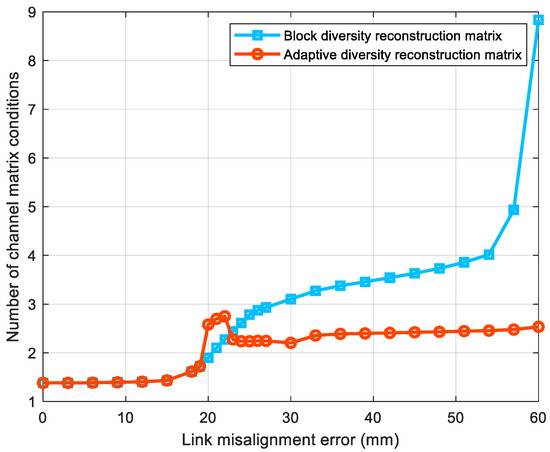
Figure 8.
Condition number of H versus the link misalignment errors for adaptive and block diversity processing.
In this study, we consider 4 QAM ACO-OFDM modulation for the simulation of an underwater large-scale optical MIMO system. The key parameters of simulation work are presented in Table 2. It is worth mentioning that we consider a coastal seawater environment for the simulation environment with an underwater visible light attenuation coefficient of 0.15.

Table 2.
Simulation parameters of the underwater optical Massive MIMO system.
Figure 9 represents the bit error ratio (BER) performance of the 16×16 MIMO system with adaptive diversity and block diversity, respectively, considering a 0 mm link misalignment error under weak turbulence environment. Since the adaptive diversity algorithm uses different combining schemes depending on the degree of link misalignment, the adaptive diversity algorithm uses the same receiver-side signal combining scheme as the block diversity scheme. So, the BER performance of the system is the same when the link misalignment level is small. While considering a higher QAM modulation order, the BER performance of the system is poorer because the system is more sensitive to noise interference with higher QAM modulation order.
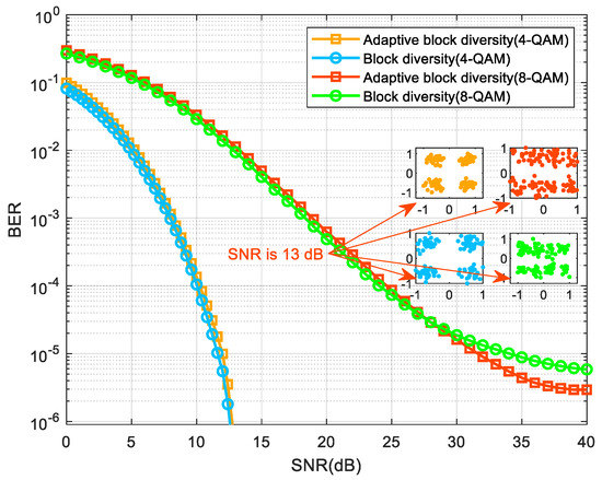
Figure 9.
BER performance for transmitter and receiver aligned system.
Figure 10 shows the BER performance of the 16 × 16 MIMO system with adaptive diversity and block diversity schemes at different QAM modulation orders in a weak turbulent environment with a link misalignment error of 23 mm. As the link misalignment error increases, the point bias of the system receiver also increases. At this time, the signal combination scheme used in the original diversity scheme at the receiver not only fails to bring signal combination gain, but also enhances the interference between signals. The adaptive diversity algorithm uses different received signal combination schemes, as the degree of link misalignment increases. By optimizing the receiver signal combination scheme, we notice a reduction in the correlation of the channel gain matrix and an improvement in the BER performance of the system.
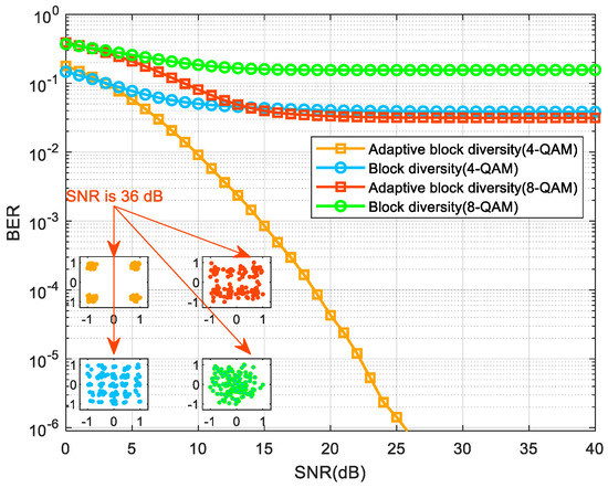
Figure 10.
BER performance under link misalignment error of 23 mm.
5. Conclusions
In this study, an adaptive diversity approach empowered by partition STBC is introduced to overcome the issue of sub-channel correlation enhancement occurring due to the joint effects of underwater link misalignment and turbulence in the process of optical signal transmission in the underwater optical Massive MIMO. The STBC technique efficiently resists the random fading of optical signals caused by turbulence. However, for the enhancement of channel correlation caused by channel misalignment, diversity technology is needed for all antennas in the MIMO system, which leads to a waste of communication resources. Therefore, a partition STBC adaptive diversity algorithm is introduced in this study, which categorizes the Massive MIMO system into various groups and utilizes diversity technology, respectively. At the same time, different receiver signal merging schemes are adopted on the basis of different degrees of link misalignment. Even when the link misalignment degree is large, the adaptive diversity approach can also use different receiver signal merging techniques depending on the degree of link misalignment, which reduces the correlation of the channel gain matrix and substantially enhances the BER performance.
The adaptive diversity algorithm proposed in this paper mainly aims at the problem of spot migration caused by link misalignment. According to different link misalignment degrees, different detector combining schemes are used to receive optical signals. However, when the link misalignment error is large enough, the light spot will deviate from the limit range received by the detector. At this time, the detector is already unable to receive the signal. In future research, we can try to regulate the transmitter angle according to the link misalignment error to reduce the interference effect caused by link misalignment.
Author Contributions
Conceptualization and channel modeling, Y.L.; methodology, Y.L. and X.C.; investigation, Y.J. and X.C.; resources, K.Z., Y.L., S.A.H.M. and X.C.; data curation, Y.J. and Y.L.; writing—original draft preparation, Y.J. and Y.L.; writing—review and editing, S.L., Y.L., S.A.H.M., Y.J. and S.L.; visualization, S.L.; supervision, S.L. and Y.L.; project administration, K.Z., Y.L. and X.C.; funding acquisition, Y.L. and X.C. All authors have read and agreed to the published version of the manuscript.
Funding
This work is supported by the National Natural Science Foundation of China under grant (62261009), the Guangxi Natural Science Foundation (2022GXNSFDA035070), and the Innovation Project of Guangxi Graduate Education (YCSW2022288).
Institutional Review Board Statement
Not applicable.
Informed Consent Statement
Not applicable.
Data Availability Statement
Enquiries about data availability should be directed to the authors.
Conflicts of Interest
The authors have no conflict of interest.
References
- Nie, J.; Tian, L.; Wang, H.; Chen, L.; Li, Z.; Yue, S.; Zhang, Z.; Yang, H. Adaptive beam shaping for enhanced underwater wireless optical communication. Opt. Express 2021, 29, 26404–26417. [Google Scholar] [CrossRef]
- Ali, M.F.; Jayakody, D.N.K.; Chursin, Y.A.; Affes, S.; Dmitry, S. Recent Advances and Future Directions on Underwater Wireless Communications. Arch. Comput. Methods Eng. 2020, 27, 1379–1412. [Google Scholar] [CrossRef]
- Ryecroft, S.; Shaw, A.; Fergus, P.; Kot, P.; Hashim, K.; Moody, A.; Conway, L. A First Implementation of Underwater Communications in Raw Water Using the 433 MHz Frequency Combined with a Bowtie Antenna. Sensors 2019, 19, 1813. [Google Scholar] [CrossRef]
- Pompili, D.; Akyildiz, I.F. Overview of networking protocols for underwater wireless communications. IEEE Commun. Mag. 2009, 47, 97–102. [Google Scholar] [CrossRef]
- Hanson, F.; Radic, S. High bandwidth underwater optical communication. Appl. Opt. 2008, 47, 277–283. [Google Scholar] [CrossRef] [PubMed]
- Huang, J.; Li, C.; Lei, Y.; Yang, L.; Xiang, Y.; Curto, A.G.; Li, Z.; Guo, L.; Cao, Z.; Hao, Y.; et al. A 20-Gbps Beam-Steered Infrared Wireless Link Enabled by a Passively Field-Programmable Metasurface. Laser Photonics Rev. 2020, 15, 2000266. [Google Scholar] [CrossRef]
- Schirripa Spagnolo, G.; Cozzella, L.; Leccese, F. Underwater Optical Wireless Communications: Overview. Sensors 2020, 20, 2261. [Google Scholar] [CrossRef]
- Oubei, H.M.; Duran, J.R.; Janjua, B.; Wang, H.-Y.; Tsai, C.-T.; Chi, Y.-C.; Ng, T.K.; Kuo, H.-C.; He, J.-H.; Alouini, M.-S.; et al. 4.8 Gbit/s 16-QAM-OFDM transmission based on compact 450-nm laser for underwater wireless optical communication. Opt. Express 2015, 23, 23302–23309. [Google Scholar] [CrossRef] [PubMed]
- Wu, T.-C.; Chi, Y.-C.; Wang, H.-Y.; Tsai, C.-T.; Lin, G.-R. Blue Laser Diode Enables Underwater Communication at 12.4 Gbps. Sci. Rep. 2017, 7, 40480. [Google Scholar] [CrossRef]
- Xu, J.; Song, Y.; Yu, X.; Lin, A.; Kong, M.; Han, J.; Deng, N. Underwater wireless transmission of high-speed QAM-OFDM signals using a compact red-light laser. Opt. Express 2016, 24, 8097–8109. [Google Scholar] [CrossRef]
- Tian, P.; Liu, X.; Yi, S.; Huang, Y.; Zhang, S.; Zhou, X.; Hu, L.; Zheng, L.; Liu, R. High-speed underwater optical wireless communication using a blue GaN-based micro-LED. Opt. Express 2017, 25, 1193–1201. [Google Scholar] [CrossRef] [PubMed]
- Han, B.; Zhao, W.; Zheng, Y.; Meng, J.; Wang, T.; Han, Y.; Wang, W.; Su, Y.; Duan, T.; Xie, X. Experimental demonstration of quasi-omni-directional transmitter for underwater wireless optical communication based on blue LED array and freeform lens. Opt. Commun. 2019, 434, 184–190. [Google Scholar] [CrossRef]
- Xu, K.; Yu, H.; Zhu, Y.-J. Channel-Adapted Spatial Modulation for Massive MIMO Visible Light Communications. IEEE Photonics Technol. Lett. 2016, 28, 2693–2696. [Google Scholar] [CrossRef]
- Wu, W.; Gao, X.; Sun, C.; Li, G.Y. Shallow underwater acoustic massive MIMO communications. IEEE Trans. Signal Process. 2021, 69, 1124–1139. [Google Scholar] [CrossRef]
- Petroni, A.; Ko, H.L.; Im, T.; Cho, Y.H.; Cusani, R.; Scarano, G.; Biagi, M. Hybrid space-frequency access for underwater acoustic networks. IEEE Access 2022, 10, 23885–23901. [Google Scholar] [CrossRef]
- Lee, B.M. Massive MIMO for underwater industrial internet of things networks. IEEE Internet Things J. 2021, 8, 15542–15552. [Google Scholar] [CrossRef]
- Joung, J.; Kurniawan, E.; Sun, S. Channel Correlation Modeling and its Application to Massive MIMO Channel Feedback Reduction. IEEE Trans. Veh. Technol. 2017, 66, 3787–3797. [Google Scholar] [CrossRef]
- Karunatilaka, D.; Zafar, F.; Kalavally, V.; Parthiban, R. LED Based Indoor Visible Light Communications: State of the Art. IEEE Commun. Surv. Tutor. 2015, 17, 1649–1678. [Google Scholar] [CrossRef]
- Biswas, S.; Masouros, C.; Ratnarajah, T. Performance Analysis of Large Multiuser MIMO Systems with Space-Constrained 2-D Antenna Arrays. IEEE Trans. Wirel. Commun. 2016, 15, 3492–3505. [Google Scholar] [CrossRef]
- Huang, A.; Tao, L.; Niu, Y. Underwater wireless optical MIMO system with spatial modulation and adaptive power allocation. Opt. Commun. 2018, 412, 21–27. [Google Scholar] [CrossRef]
- Wang, T.Q.; Sekercioglu, Y.A.; Armstrong, J. Analysis of an Optical Wireless Receiver Using a Hemispherical Lens with Application in MIMO Visible Light Communications. J. Light. Technol. 2013, 31, 1744–1754. [Google Scholar] [CrossRef]
- Chen, T.; Liu, L.; Tu, B.; Zheng, Z.; Hu, W. High-Spatial-Diversity Imaging Receiver Using Fisheye Lens for Indoor MIMO VLCs. IEEE Photonics Technol. Lett. 2014, 26, 2260–2263. [Google Scholar] [CrossRef]
- Wang, J.; Yin, H.; Ji, X.; Liang, Y. Performance Analysis of MIMO-mQAM System with Pointing Errors and Beam Spreading in Underwater Málaga Turbulence Channel. J. Mar. Sci. Eng. 2023, 11, 633. [Google Scholar] [CrossRef]
- Wei, J.; Gong, C.; Huang, N.; Xu, Z. Channel Modeling and Signal Processing for Array-Based Visible Light Communication System Under Link Misalignment. IEEE Photonics J. 2022, 14, 7318710. [Google Scholar] [CrossRef]
- Ansari, I.S.; Yilmaz, F.; Alouini, M.S. Performance Analysis of Free-Space Optical Links Over Málaga (M) Turbulence Channels with Pointing Errors. IEEE Trans. Wirel. Commun. 2016, 15, 91–102. [Google Scholar] [CrossRef]
- Rahman, Z.; Tailor, N.V.; Zafaruddin, S.M.; Chaubey, V.K. Unified Performance Assessment of Optical Wireless Communication Over Multi-Layer Underwater Channels. IEEE Photonics J. 2022, 14, 7349114. [Google Scholar] [CrossRef]
- Jamali, M.V.; Salehi, J.A.; Akhoundi, F. Performance Studies of Underwater Wireless Optical Communication Systems with Spatial Diversity: MIMO Scheme. IEEE Trans. Commun. 2017, 65, 1176–1192. [Google Scholar] [CrossRef]
- Sharifzadeh, M.; Ahmadirad, M. Performance analysis of underwater wireless optical communication systems over a wide range of optical turbulence. Opt. Commun. 2018, 427, 609–616. [Google Scholar] [CrossRef]
- Bhatnagar, M.R.; Anees, S. On the Performance of Alamouti Scheme in Gamma-Gamma Fading FSO Links With Pointing Errors. IEEE Wirel. Commun. Lett. 2015, 4, 94–97. [Google Scholar] [CrossRef]
- Shi, J.; Huang, X.; Wang, Y.; Tao, L.; Chi, N. Improved performance of a high speed 2×2 MIMO VLC network based on EGC-STBC. In Proceedings of the 2015 European Conference on Optical Communication (ECOC), Valencia, Spain, 27 September–1 October 2015; pp. 1–3. [Google Scholar]
- Fu, J.; Zhu, K.; Mohsan, S.A.H.; Li, Y. Channel Model and Signal-Detection Algorithm for the Combined Effects of Turbulence and Link Misalignment in Underwater Optical Massive MIMO Systems. J. Mar. Sci. Eng. 2023, 11, 547. [Google Scholar] [CrossRef]
- Wang, P.; Li, C.; Xu, Z. A Cost-Efficient Real-Time 25 Mb/s System for LED-UOWC: Design, Channel Coding, FPGA Implementation, and Characterization. J. Light. Technol. 2018, 36, 2627–2637. [Google Scholar] [CrossRef]
- Ijeh, I.C.; Khalighi, M.A.; Elamassie, M.; Hranilovic, S.; Uysal, M. Outage probability analysis of a vertical underwater wireless optical link subject to oceanic turbulence and pointing errors. J. Opt. Commun. Netw. 2022, 14, 439–453. [Google Scholar] [CrossRef]
- Sandalidis, H.G.; Tsiftsis, T.A.; Karagiannidis, G.K. Optical Wireless Communications with Heterodyne Detection Over Turbulence Channels With Pointing Errors. J. Light. Technol. 2009, 27, 4440–4445. [Google Scholar] [CrossRef]
Disclaimer/Publisher’s Note: The statements, opinions and data contained in all publications are solely those of the individual author(s) and contributor(s) and not of MDPI and/or the editor(s). MDPI and/or the editor(s) disclaim responsibility for any injury to people or property resulting from any ideas, methods, instructions or products referred to in the content. |
© 2023 by the authors. Licensee MDPI, Basel, Switzerland. This article is an open access article distributed under the terms and conditions of the Creative Commons Attribution (CC BY) license (https://creativecommons.org/licenses/by/4.0/).
