
A Serial Fault-Tolerant Topology Based on Sustainable Reconfiguration for Grid-Connected Inverter


Abstract
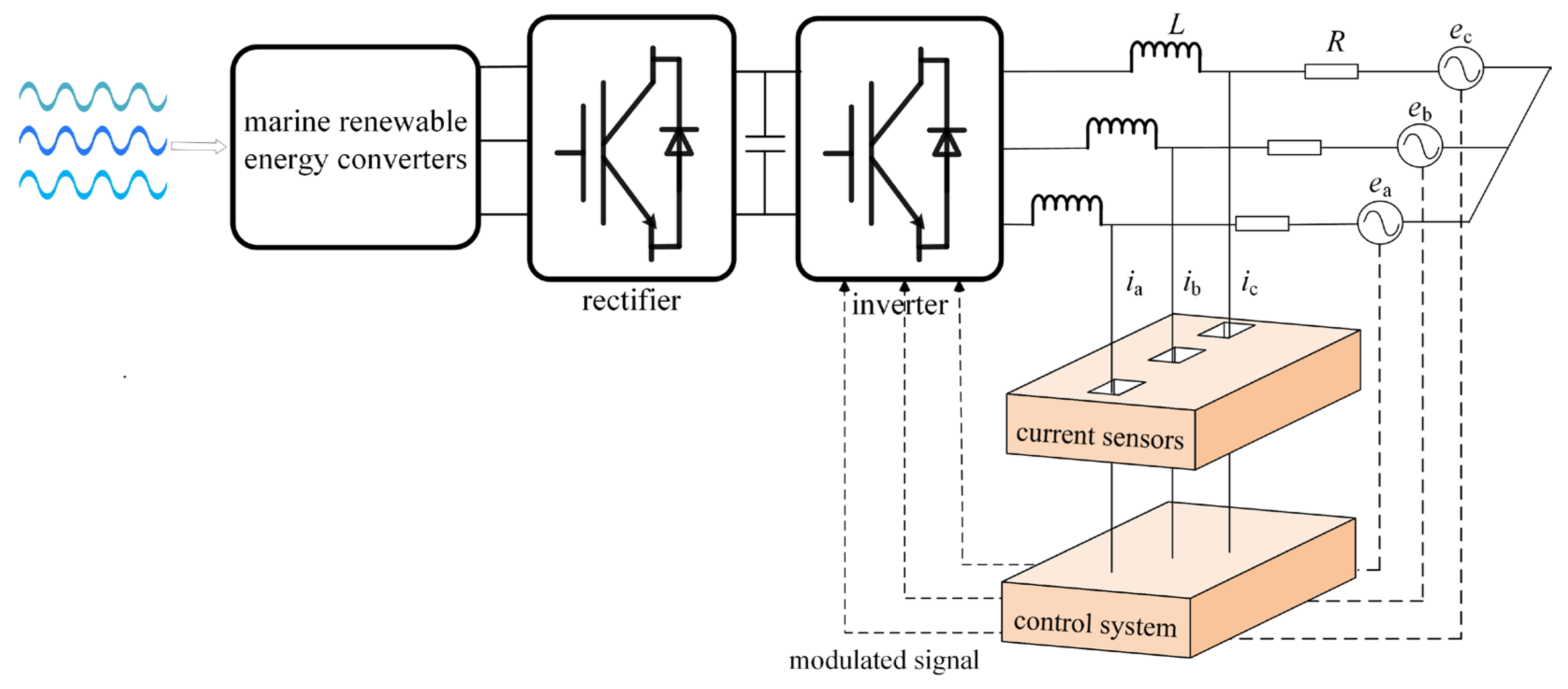
:1. Introduction
2. Fault Analysis for Grid-Connected Inverters
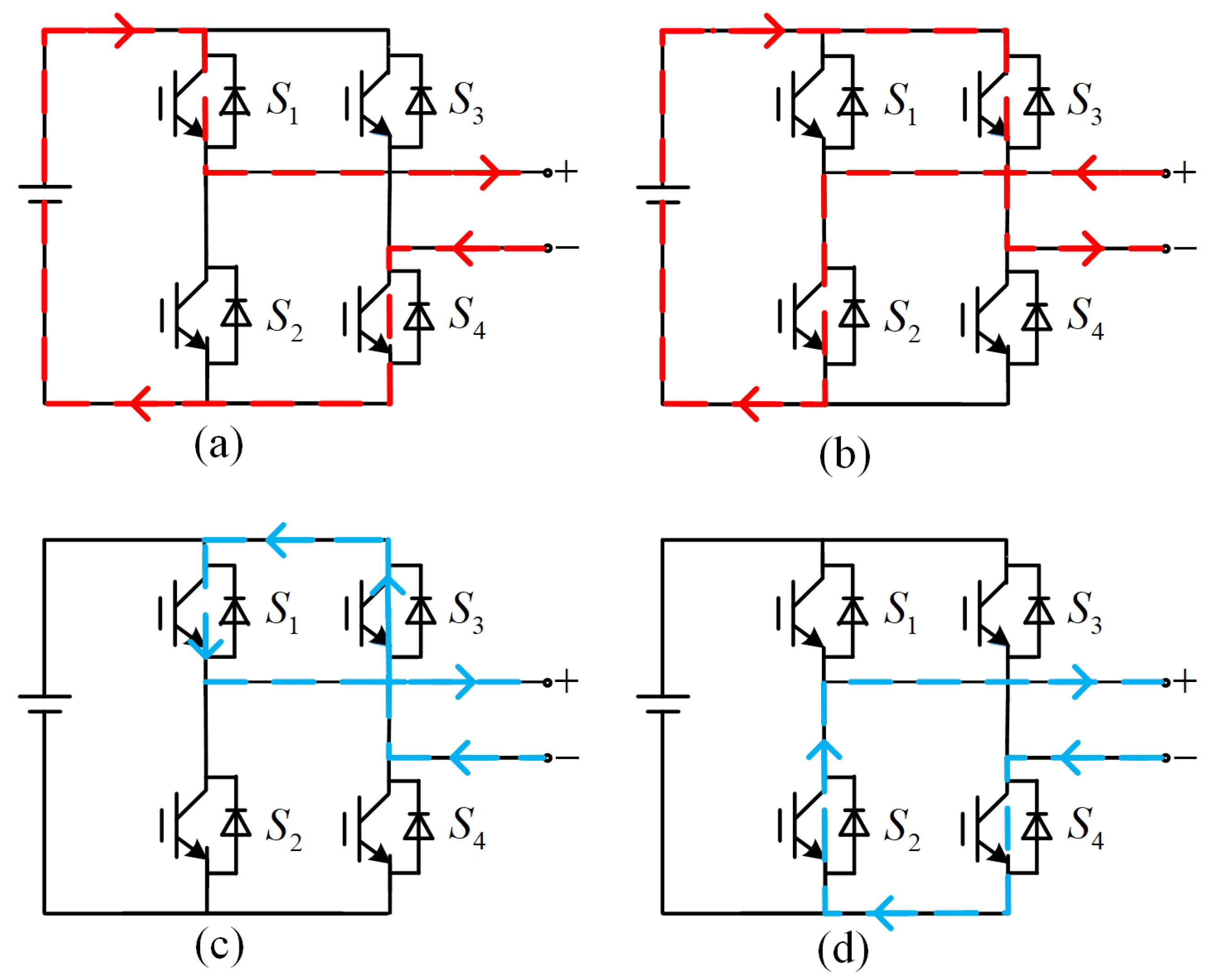
2.1. Fault Effect on the H-Bridge
2.2. Fault Effect on the Grid-Connected Inverter
2.3. Problem Description
3. Materials and Methods
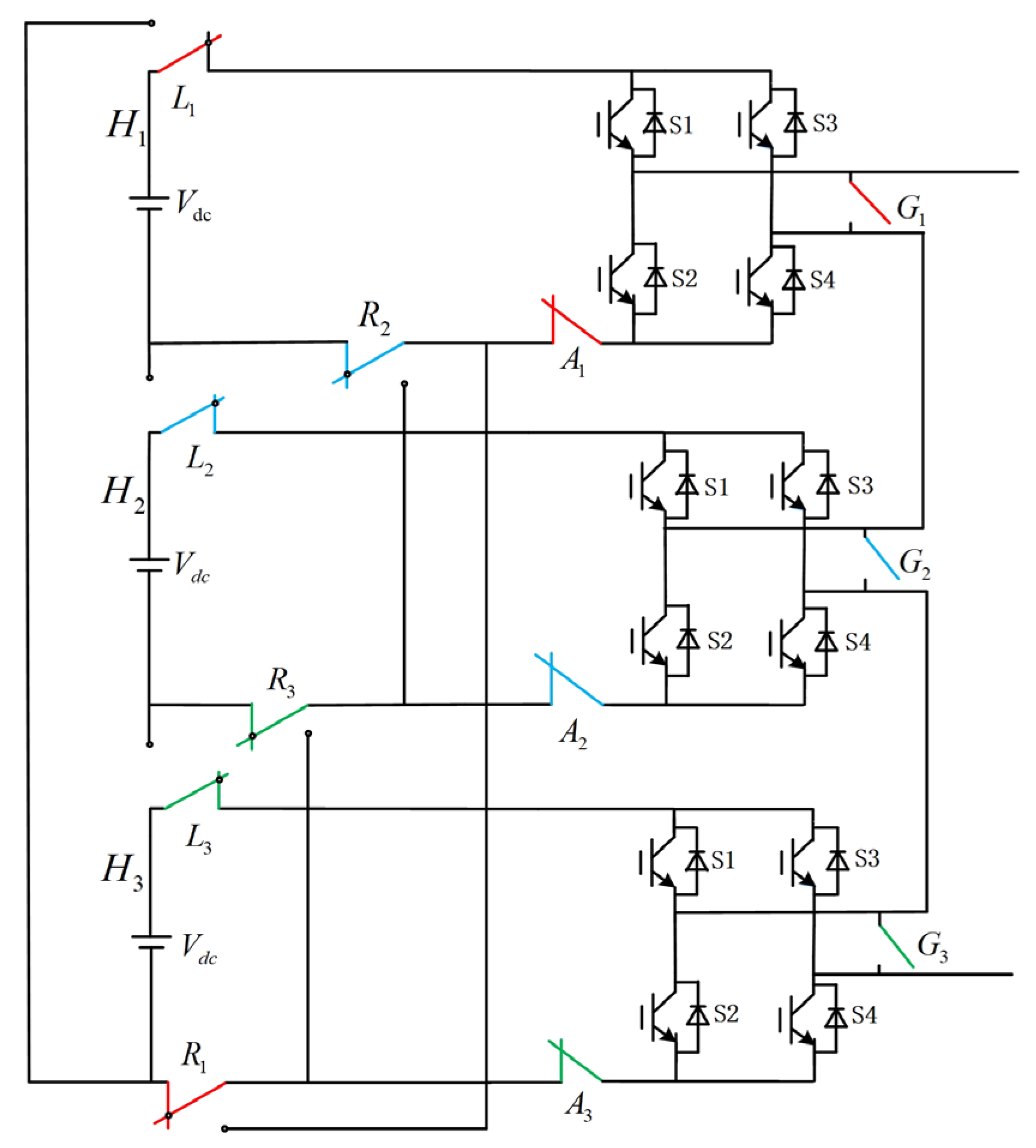
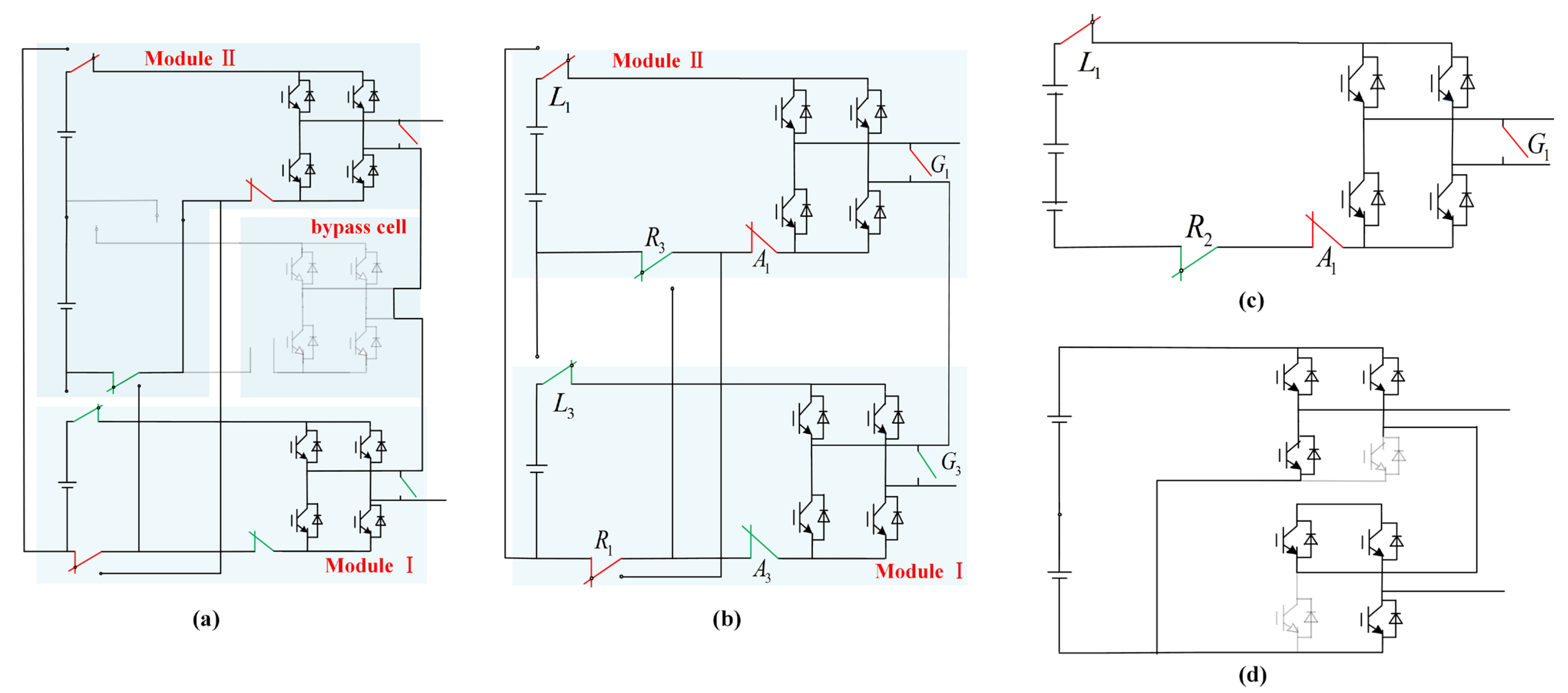
3.1. Serial Fault-Tolerant Topology Based on Sustainable Reconfiguration
- Mode I:
- Mode II:
- Mode III:
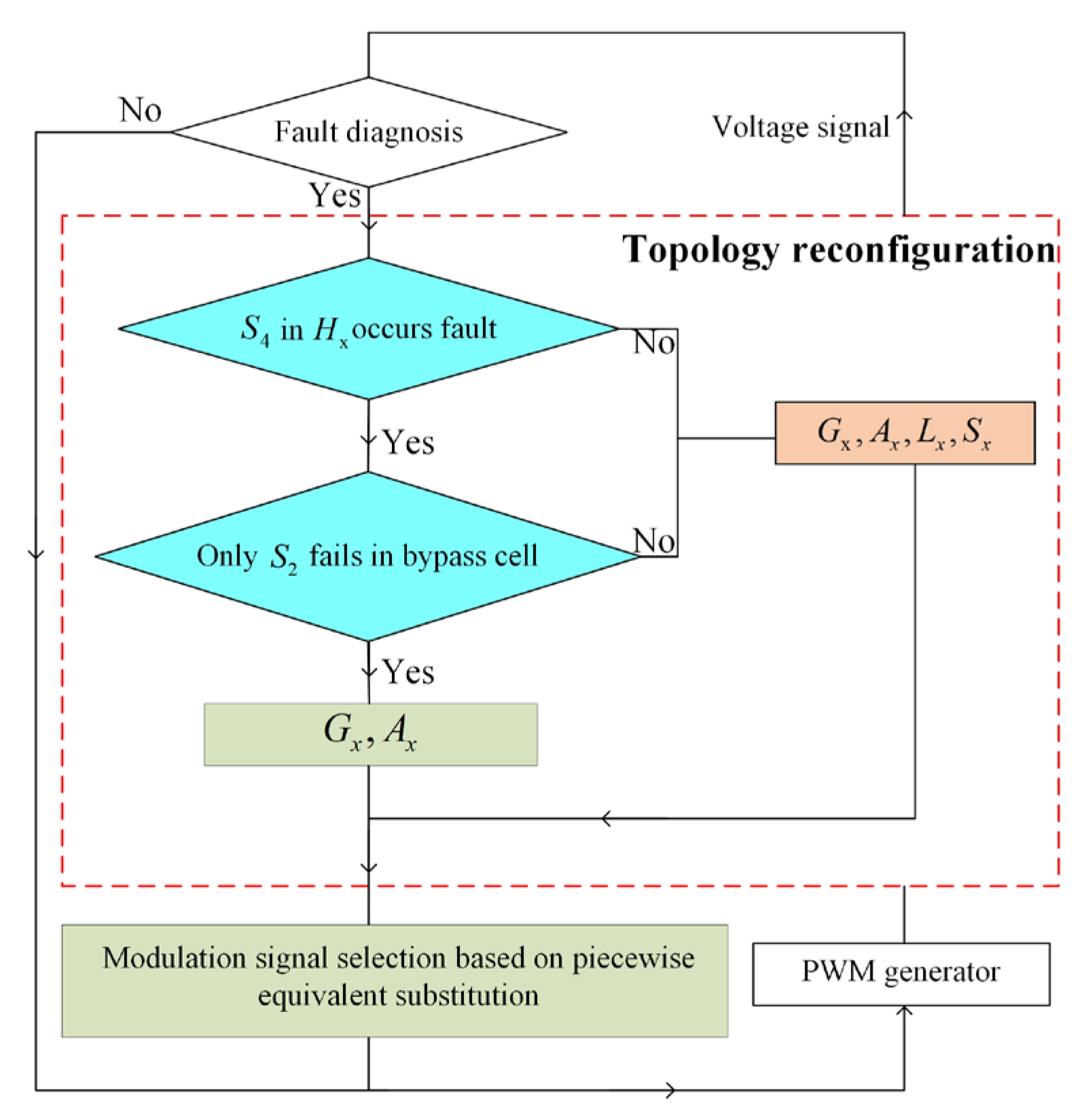
3.2. Modulation Signal Selection Based on Piecewise Equivalent Substitution
3.2.1. Determination of Module
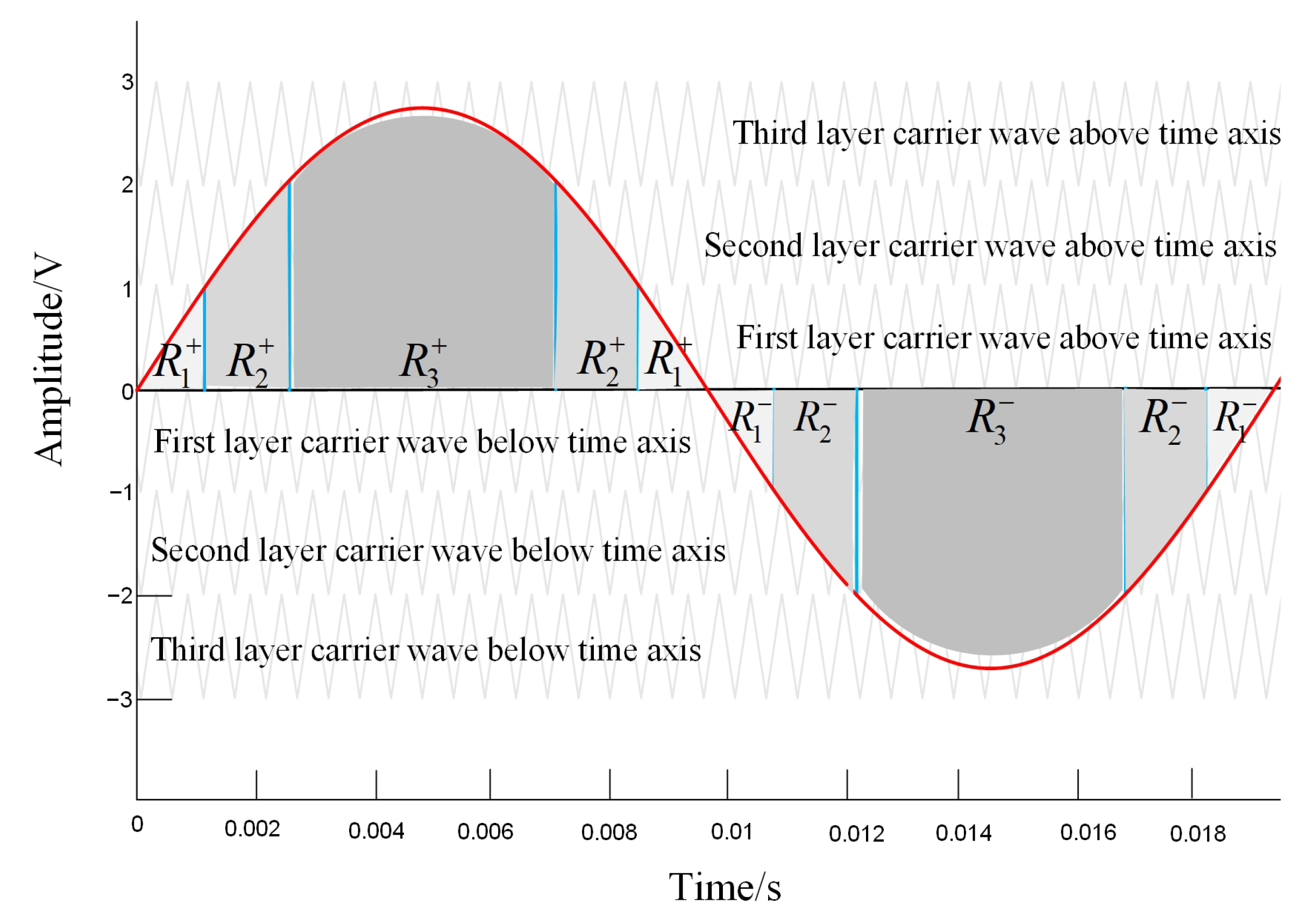
3.2.2. Division of Time Regions
3.2.3. Selection of Modulation Signal
- Case 1 (three Module I in the topological space):
- Case 2 (a Module I and a Module II in the topological space):
- Case 3 (a Module III in the topological space):
4. Results
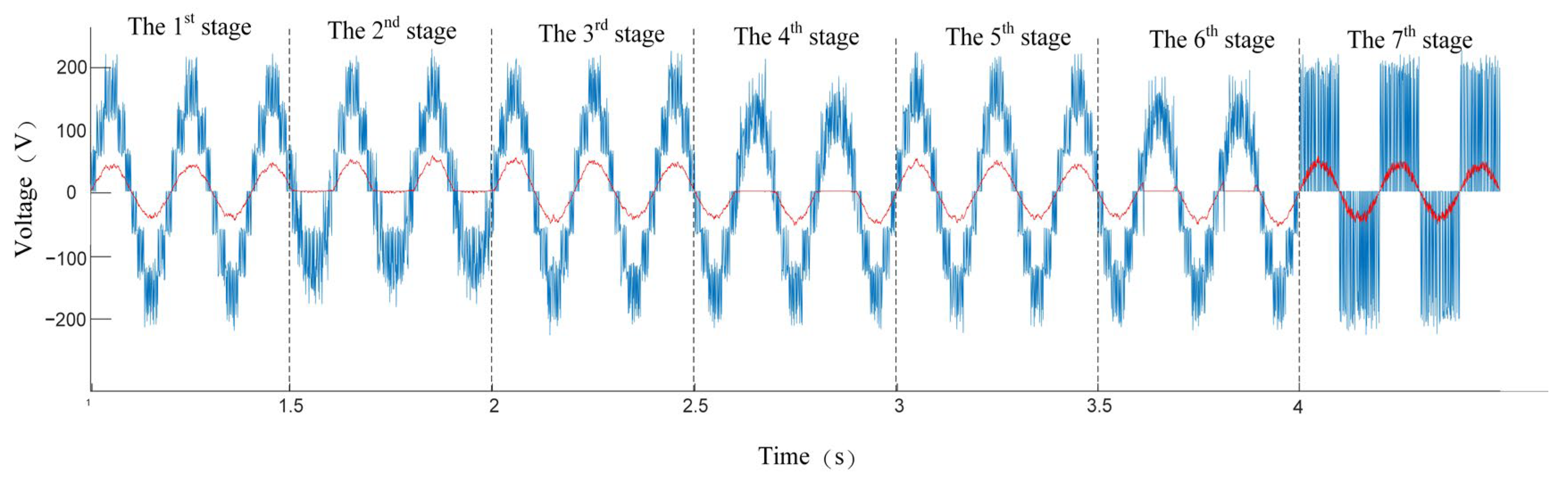
4.1. Simulation Results of the SF-TC Method
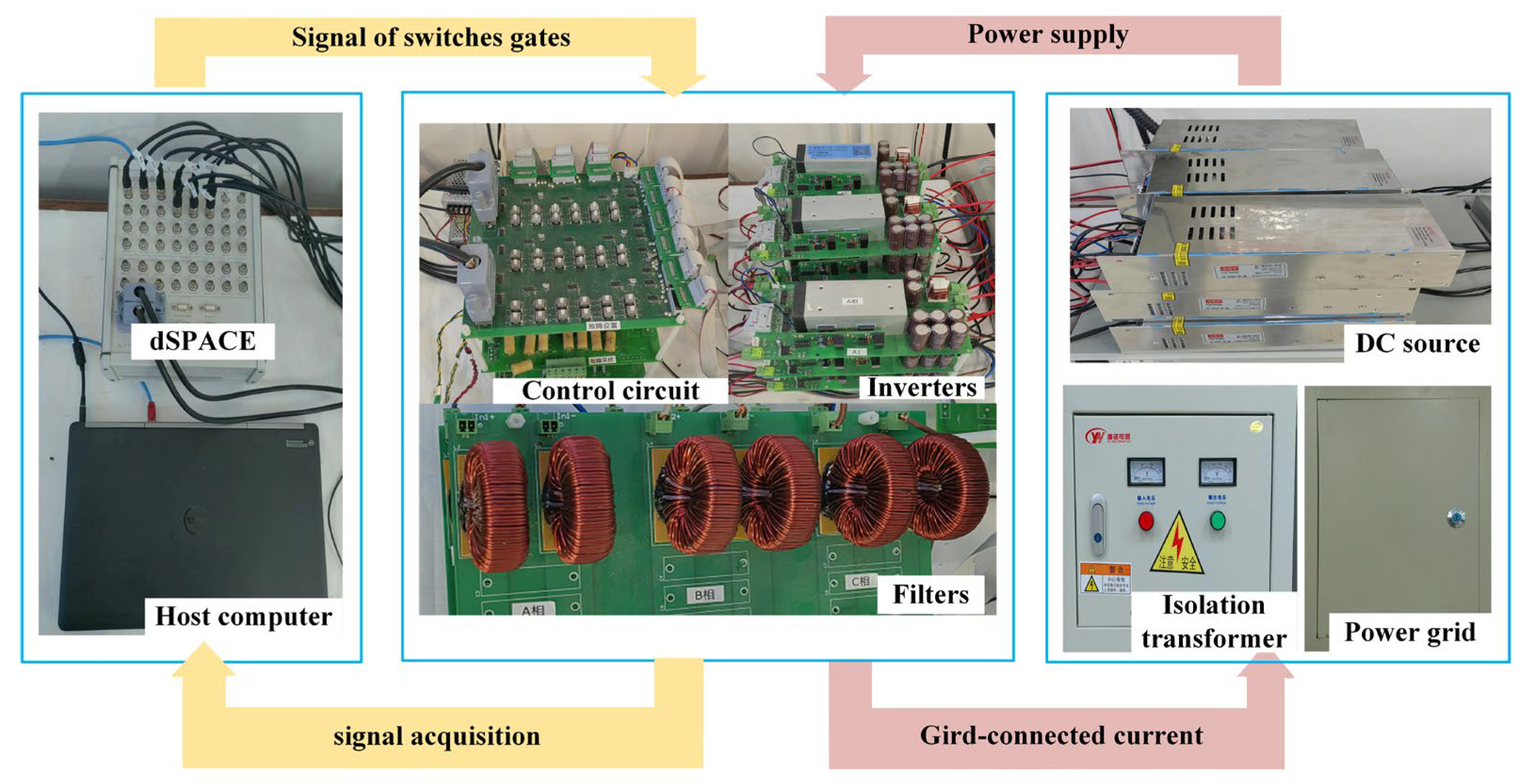
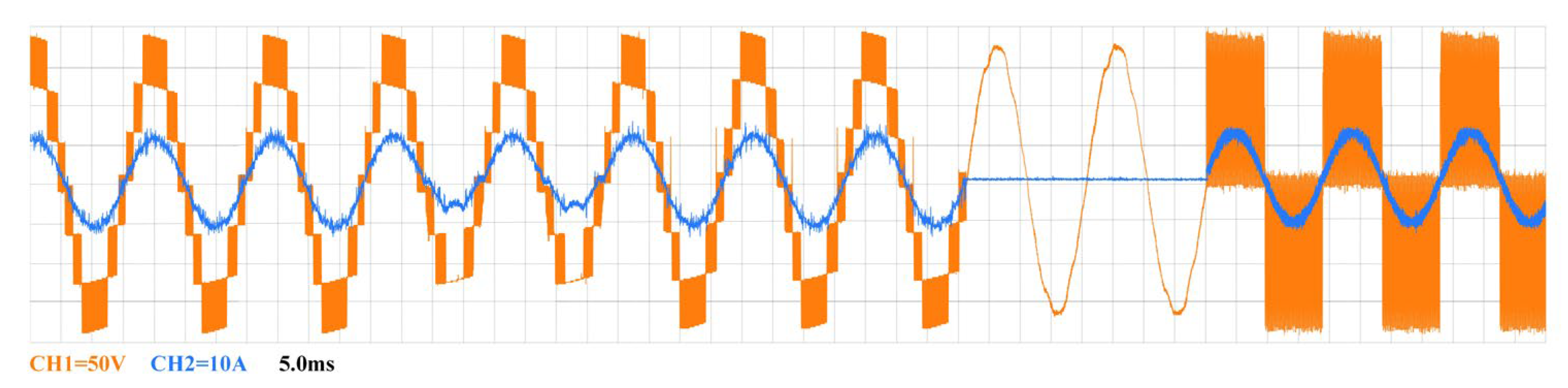
4.2. Experimental Results of the SF-TC Method
5. Discussion
6. Conclusions
Author Contributions
Funding
Institutional Review Board Statement
Informed Consent Statement
Data Availability Statement
Conflicts of Interest
References
- Zhao, J.; Huang, M.; Yan, H.; Tse, C.K.; Zha, X. Nonlinear and transient stability analysis of phase-locked loops in grid-connected converters. IEEE Trans. Power Electron. 2021, 36, 1018–1029. [Google Scholar] [CrossRef]
- Chen, C.-H.; Su, N.-J. Global Trends and Characteristics of Offshore Wind Farm Research over the Past Three Decades: A Bibliometric Analysis. J. Mar. Sci. Eng. 2022, 10, 1339. [Google Scholar] [CrossRef]
- Li, M.; Luo, H.; Zhou, S.; Kumar, G.M.S.; Guo, X.; Law, T.C.; Cao, S. State-of-the-art review of the flexibility and feasibility of emerging offshore and coastal ocean energy technologies in East and Southeast Asia. Renew. Sustain. Energy Rev. 2022, 162, 112404. [Google Scholar] [CrossRef]
- Clemente, D.; Rosa-Santos, P.R.; Taveira-Pinto, F. On the potential synergies and applications of wave energy converters: A review. Renew. Sustain. Energy Rev. 2021, 135, 110162. [Google Scholar] [CrossRef]
- Zeng, H.; Zhao, Y.; Wang, X.; He, T.; Zhang, J. Modeling of Ship DC Power Grid and Research on Secondary Control Strategy. J. Mar. Sci. Eng. 2022, 10, 2037. [Google Scholar] [CrossRef]
- Wang, L.; Lin, C.; Wu, H.; Prokhorov, A.V. Stability Analysis of a Microgrid System With a Hybrid Offshore Wind and Ocean Energy Farm Fed to a Power Grid Through an HVDC Link. IEEE Trans. Ind. Appl. 2018, 54, 2012–2022. [Google Scholar] [CrossRef]
- Canciello, G.; Cavallo, A.; Schiavo, A.; Russo, A. Multi-objective adaptive sliding manifold control for more electric aircraft. ISA Trans. 2020, 107, 316–328. [Google Scholar] [CrossRef]
- Barelli, L.; Pelosi, D.; Ciupageanu, D.A.; Ottaviano, P.A.; Longo, M.; Zaninelli, D. HESS in a Wind Turbine Generator: Assessment of Electric Performances at Point of Common Coupling with the Grid. J. Mar. Sci. Eng. 2021, 9, 1413. [Google Scholar] [CrossRef]
- Hill, C.A.; Such, M.C.; Chen, D.; Gonzalez, J.; Grady, W.M. Battery Energy Storage for Enabling Integration of Distributed Solar Power Generation. IEEE Trans. Smart Grid. 2012, 3, 850–857. [Google Scholar] [CrossRef]
- Tiwari, S.K.; Singh, B.; Goel, P.K. Design and Control of Microgrid Fed by Renewable Energy Generating Sources. IEEE Trans. Ind. Appl. 2018, 54, 2041–2050. [Google Scholar] [CrossRef]
- Bhende, C.N.; Mishra, S.; Malla, S.G. Permanent Magnet Synchronous Generator-Based Standalone Wind Energy Supply System. IEEE Trans. Sustain. Energy 2011, 2, 361–373. [Google Scholar] [CrossRef]
- Ganjian-Aboukheili, M.; Shahabi, M.; Shafiee, Q.; Guerrero, J.M. Seamless Transition of Microgrids Operation From Grid-Connected to Islanded Mode. IEEE Trans. Power Electron. 2020, 11, 2106–2114. [Google Scholar] [CrossRef]
- Qanbari, T.; Tousi, B. Single-Source Three-Phase Multilevel Inverter Assembled by Three-Phase Two-Level Inverter and Two Single-Phase Cascaded H-Bridge Inverters. IEEE Trans. Power Electron. 2021, 36, 5204–5212. [Google Scholar] [CrossRef]
- Gupta, K.K.; Ranjan, A.; Bhatnagar, P.; Sahu, L.K.; Jain, S. Multilevel Inverter Topologies with Reduced Device Count: A Review. IEEE Trans. Power Electron. 2016, 31, 135–151. [Google Scholar] [CrossRef]
- Wang, B.; Cai, J.; Du, X.; Zhou, L. Review of power semiconductor device reliability for power converters. CPSS. Trans. Power. Electron. Appl. 2017, 2, 101–117. [Google Scholar] [CrossRef]
- Sher, H.A.; Paracha, Z.J.; Khan, Y.; Addoweesh, K.E. Fault analysis of an inverter fed induction motor under DC link capacitor short circuit condition. In Proceedings of the 5th Global Conference on Power Control and Optimization, Dubai, United Arab Emirates, 1–3 June 2011. [Google Scholar]
- Papadopoulos, C.; Boksteen, B.; Paques, G.; Corvasce, C. Humidity Robustness of IGBT Guard Ring Termination PCIM Europe 2019. In Proceedings of the International Exhibition and Conference for Power Electronics Intelligent Motion, Renewable Energy and Energy Management, Nuremberg, Germany, 7–9 May 2019. [Google Scholar]
- Ali, M.; Din, Z.; Solomin, E.; Cheema, K. Open switch fault diagnosis of cascade H-bridge multi-level inverter in distributed power generators by machine learning algorithms. Energy Rep. 2021, 7, 8929–8942. [Google Scholar] [CrossRef]
- Xia, Y.; Xu, Y.; Gou, B. A Data-Driven Method for IGBT Open-Circuit Fault Diagnosis Based on Hybrid Ensemble Learning and Sliding-Window Classification. IEEE Trans. Industr. Inform. 2019, 16, 5223–5233. [Google Scholar] [CrossRef]
- Xie, D.; Wang, H.; Ge, X.; Deng, Q.; Gou, B.; Ma, L. A Voltage-Based Multiple Fault Diagnosis Approach for Cascaded H-Bridge Multilevel Converters. IEEE J. Emerg. Sel. Top. Power Electron. 2022, 10, 5092–5106. [Google Scholar] [CrossRef]
- Wang, T.; Xu, H.; Han, J.; Elbouchikhi, E.; Benbouzid, M.E.H. Cascaded H-Bridge Multilevel Inverter System Fault Diagnosis Using a PCA and Multiclass Relevance Vector Machine Approach. IEEE Trans. Power Electron. 2015, 30, 7006–7018. [Google Scholar] [CrossRef]
- Cai, B.; Zhao, Y.; Liu, H.; Xie, M. A Data-Driven Fault Diagnosis Methodology in Three-Phase Inverters for PMSM Drive Systems. IEEE Trans. Power Electron. 2017, 32, 5590–5600. [Google Scholar] [CrossRef]
- Pires, V.F.; Amaral, T.G.; Foito, D.; Pires, A.J. Cascaded H-bridge multilevel inverter with a fault detection scheme based on the statistic moments indexes. In Proceedings of the 2017 11th IEEE International Conference on Compatibility, Power Electronics and Power Engineering (CPE-POWERENG), Cadiz, Spain, 1 May 2017. [Google Scholar] [CrossRef]
- Wang, T.; Zhang, J.; Wang, H.; Wang, Y.; Diallo, D.; Benbouzid, M. Multi-mode fault-tolerant control strategy for cascaded H-bridge multilevel inverters. IET Power Electron. 2020, 13, 3119–3126. [Google Scholar] [CrossRef]
- Geng, C.; Wang, T.; Tang, T.; Benbouzid, M.; Qin, H. Fault-tolerant control strategy of the cascaded five-level inverter based on divided voltage modulation algorithm. In Proceedings of the 2016 IEEE 8th International Power Electronics and Motion Control Conference (IPEMC-ECCE Asia), Hefei, China, 14 July 2016. [Google Scholar] [CrossRef]
- Song, W.; Huang, A.Q. Fault-Tolerant Design and Control Strategy for Cascaded H-Bridge Multilevel Converter-Based STATCOM. IEEE Trans. Ind. Electron. 2010, 57, 2700–2708. [Google Scholar] [CrossRef]
- Rahman, S.; Meraj, M.; Iqbal, A.; Ben-Brahim, L. Novel Voltage Balancing Algorithm for Single-phase Cascaded Multilevel Inverter for Post-module Failure Operation in Solar PV Applications. IET Renew. Power Gener. 2018, 13, 427–437. [Google Scholar] [CrossRef]
- Jalhotra, M.; Gautam, S.; Kumar, L.; Gupta, S.; Chander, A.H. Fault Tolerance and Energy Sharing Analysis of a Single Phase Multilevel Inverter Topology. In Proceedings of the IECON 2018—44th Annual Conference of the IEEE Industrial Electronics Society, Washington, DC, USA, 30 December 2018. [Google Scholar] [CrossRef]
- Saketi, S.; Chaturvedi, P.; Yadeo, D. A New Fault Tolerant Single Phase 5-Level Inverter Topology. In Proceedings of the 2018 8th IEEE India International Conference on Power Electronics (IICPE) IEEE, Jaipur, India, 9 May 2019. [Google Scholar] [CrossRef]
- Mhiesan, H.; Wei, Y.; Siwakoti, Y.; Mantooth, A. A Fault-Tolerant Hybrid Cascaded H-Bridge Multilevel Inverter. IEEE Trans. Power Electron. 2020, 35, 12702–12715. [Google Scholar] [CrossRef]
- Yang, H.; Wang, T.; Tang, Y. A Hybrid Fault-Tolerant Control Strategy for Three-phase Cascaded Multilevel Inverters Based on Half-bridge Recombination Method. In Proceedings of the IECON 2021—47th Annual Conference of the IEEE Industrial Electronics Society, Toronto, ON, Canada, 10 November 2021. [Google Scholar] [CrossRef]
- Ahmadi, R.; Aleenejad, M.; Mahmoudi, H.; Jafarishiadeh, S. Reduced Number of Auxiliary H-Bridge Power Cells for Post-Fault Operation of Three Phase Cascaded H-Bridge Inverter. IET Power Electron. 2019, 12, 2923–2931. [Google Scholar] [CrossRef]
- Salimian, H.; Iman-Eini, H. Fault-Tolerant Operation of Three-Phase Cascaded H-Bridge Converters Using an Auxiliary Module. IEEE Trans. Ind. Electron. 2017, 64, 1018–1027. [Google Scholar] [CrossRef]
- Aleenejad, M.; Iman-Eini, H.; Farhangi, S. Modified space vector modulation for fault-tolerant operation of multilevel cascaded H-bridge inverters. IET Power Electron. 2013, 6, 742–751. [Google Scholar] [CrossRef]
- Zhao, Z.; Wang, T.; Benbouzid, M. A fault-tolerant reconfiguration system based on pilot switch for grid-connected inverters. Microelectron. Reliab. 2022, 131, 114511. [Google Scholar] [CrossRef]
- Jahan, H.; Panahandeh, F.; Abapour, M.; Tohidi, S. Reconfigurable Multilevel Inverter With Fault-Tolerant Ability. IEEE Trans. Power Electron. 2018, 33, 7880–7893. [Google Scholar] [CrossRef]
- Haji-Esmaeili, M.; Naseri, M.; Khoun-Jahan, H.; Abapour, M. Fault-tolerant structure for cascaded H-bridge multilevel inverter and reliability evaluation. IET Power Electron. 2017, 10, 59–70. [Google Scholar] [CrossRef]
- Murtaza, A.F.; Sher, H.A.; Al-Haddad, K.; Spertino, F. Module Level Electronic Circuit Based PV Array for Identification and Reconfiguration of Bypass Modules. IEEE Trans. Energy Convers. 2021, 36, 380–389. [Google Scholar] [CrossRef]
- Murtaza, A.F.; Sher, H.A. A Reconfiguration Circuit to Boost the Output Power of a Partially Shaded PV String. Energies 2023, 16, 622. [Google Scholar] [CrossRef]
- Volke, A.; Hornkamp, M. IGBT Modules: Technologies, Driver and Applications, 2nd ed.; China Machine Press: Beijing, China, 2016; pp. 103–104. [Google Scholar]


| 0.4 | 0.5 | 0.6 | 0.7 | 0.8 | 0.9 | 1 | ||
|---|---|---|---|---|---|---|---|---|
| Factor | 1 | 1 | 1 | 1 | 1.1 | 1.3 | 1.8 | 4 |
| Arm | ||||||
|---|---|---|---|---|---|---|
| Modulation signal |
| Region | ||||||
|---|---|---|---|---|---|---|
| Module | Parameters |
|---|---|
| DC source voltage ) | 195 V |
| Grid side voltage (v) | 130 V |
| Grid frequency (f) | 50 Hz |
| Filter inductance (L) | 4 mH |
| Parameter | Value |
|---|---|
| Switching frequency | 5 kHz |
| DC source | 65 V |
| Isolation transformer | 1:2 |
| Filter inductance | 6 mH |
| Grid frequency | 50 Hz |
| q-axis reference current | 0 A |
| d-axis reference current | 4 A |
| Scheme | Proposed | [24] | [26] | [30] | [35] | [36] | [37] |
|---|---|---|---|---|---|---|---|
| Number of relays | 12 | 0 | 3 | 0 | 8 | 2 | 12 |
| Ability to keep voltage amplitude | High | Low | High | Medium | Low | Medium | High |
| Ability to keep voltage quality | High | Low | High | Medium | Low | Medium | High |
| Applicable to BESS | Yes | Yes | No | Yes | Yes | Yes | Yes |
| Ability to work in asymmetric mode | No | No | No | No | No | Yes | No |
| The ability of multiple fault tolerance | High | Low | Medium | Low | Low | Medium | High |
Disclaimer/Publisher’s Note: The statements, opinions and data contained in all publications are solely those of the individual author(s) and contributor(s) and not of MDPI and/or the editor(s). MDPI and/or the editor(s) disclaim responsibility for any injury to people or property resulting from any ideas, methods, instructions or products referred to in the content. |
© 2023 by the authors. Licensee MDPI, Basel, Switzerland. This article is an open access article distributed under the terms and conditions of the Creative Commons Attribution (CC BY) license (https://creativecommons.org/licenses/by/4.0/).
Share and Cite
Zhang, Z.; Wang, T.; Chen, G.; Amirat, Y. A Serial Fault-Tolerant Topology Based on Sustainable Reconfiguration for Grid-Connected Inverter. J. Mar. Sci. Eng. 2023, 11, 751. https://doi.org/10.3390/jmse11040751
Zhang Z, Wang T, Chen G, Amirat Y. A Serial Fault-Tolerant Topology Based on Sustainable Reconfiguration for Grid-Connected Inverter. Journal of Marine Science and Engineering. 2023; 11(4):751. https://doi.org/10.3390/jmse11040751
Chicago/Turabian StyleZhang, Zhonglin, Tianzhen Wang, Guodong Chen, and Yassine Amirat. 2023. "A Serial Fault-Tolerant Topology Based on Sustainable Reconfiguration for Grid-Connected Inverter" Journal of Marine Science and Engineering 11, no. 4: 751. https://doi.org/10.3390/jmse11040751
APA StyleZhang, Z., Wang, T., Chen, G., & Amirat, Y. (2023). A Serial Fault-Tolerant Topology Based on Sustainable Reconfiguration for Grid-Connected Inverter. Journal of Marine Science and Engineering, 11(4), 751. https://doi.org/10.3390/jmse11040751