1. Introduction
Three-dimensional computer-aided design (3D CAD) models are used in various ways for design review and production support because they are highly legible [
1,
2]. A CAD model of a ship or offshore plant consisting of millions of parts contains information related not only to geometry but also to design and production, resulting in a large amount of data. Additionally, using a 3D CAD model can be inefficient because triangular mesh generation is required for visualization. To address this problem, lightweight models composed of triangular meshes have been increasingly used [
3,
4,
5,
6]. Typical lightweight file formats include STL (stereolithography), JT (Jupiter tessellation), 3D XML (3D extensible markup language), XVL (extendable virtual world description language), and VRML (virtual reality modeling language) [
7,
8]. The lightweight model created by converting a 3D CAD model can be used to check for interferences that may occur during installation and election, calculation of material quantity, and planning of the production process [
9].
A lightweight model of a ship or offshore plant is generated through several stages, including conversion into a neutral format such as SAT, IGES, or STEP files, tessellation, weight-lightening, and linkage to design and production information [
10]. The lightweight model can vary depending on triangular element density, file format, and compression method. However, if only geometric information is saved, it can be created in 5 to 10% of the size of the 3D CAD model [
5]. Due to the nature of building ships and offshore plants, their designs change frequently. In such cases, the updated 3D CAD model is automatically converted into lightweight files, and the application program uses them as needed [
11].
Ships and offshore plants are typically built by assembling blocks as basic units [
12]. Welding is the most expensive process in building blocks. Therefore, manufacturing time, workshops, welding equipment, and manpower are determined based on the welding material quantity [
13,
14,
15,
16]. In particular, the welding material quantity should be calculated for the subsections of the blocks for efficient work planning. The factors affecting the quantity of welding material include bead length (welding length), welding type, welding position, assembly state, welding leg, and automation. In previous studies on welding material quantity estimation, a method based on geometric information in the 3D CAD model has been used [
17,
18,
19,
20]. However, it can only estimate the quantity at the block level, making it difficult to extract information at the subsection level.
Welding can cause numerous quality problems [
21,
22,
23]. Recently, welding automation robots have been widely used to reduce costs in the welding process and improve welding quality. Welding is classified into three categories: manual welding, which is performed purely by a worker; semiautomatic welding, which uses a carriage; and automatic welding, which uses an articulated or gantry robot. In the semiautomatic welding process, the path is defined by a rail or manually without a preset path. In automatic welding, the welding path is generated in advance, and the robot follows this path to perform the welding.
Weld line information is stored within the 3D CAD system used by the shipyard. This information is mainly used to estimate the work volume for the welding process. However, it is often missing in the design and modification processes. Additionally, it is necessary to build a separate database and develop the interface to this database in order to use this information for the welding material quantity estimation and the welding path generation.
Lightweight models have smaller data sizes, relatively few security problems, and simple file structures, making them considerably more accessible than 3D CAD models. Furthermore, most shipyards have been using lightweight models in recent years. Considering this trend, a method to generate weld lines from the lightweight model without any use of 3D CAD models is proposed in this paper. Additionally, calculating bead length for welding material quantity estimation and planning welding paths are presented as applications of the generated weld lines. To the best of our knowledge, this is the first study that attempts to use the lightweight model to support the welding process in shipyards.
The remainder of this paper is organized as follows:
Section 2 introduces the lightweight model.
Section 3 presents a method to generate weld lines from the lightweight model.
Section 4 discusses two applications of generated weld lines: bead length calculation for welding material quantity estimation and welding path planning.
Section 5 concludes this study.
2. The Lightweight Model
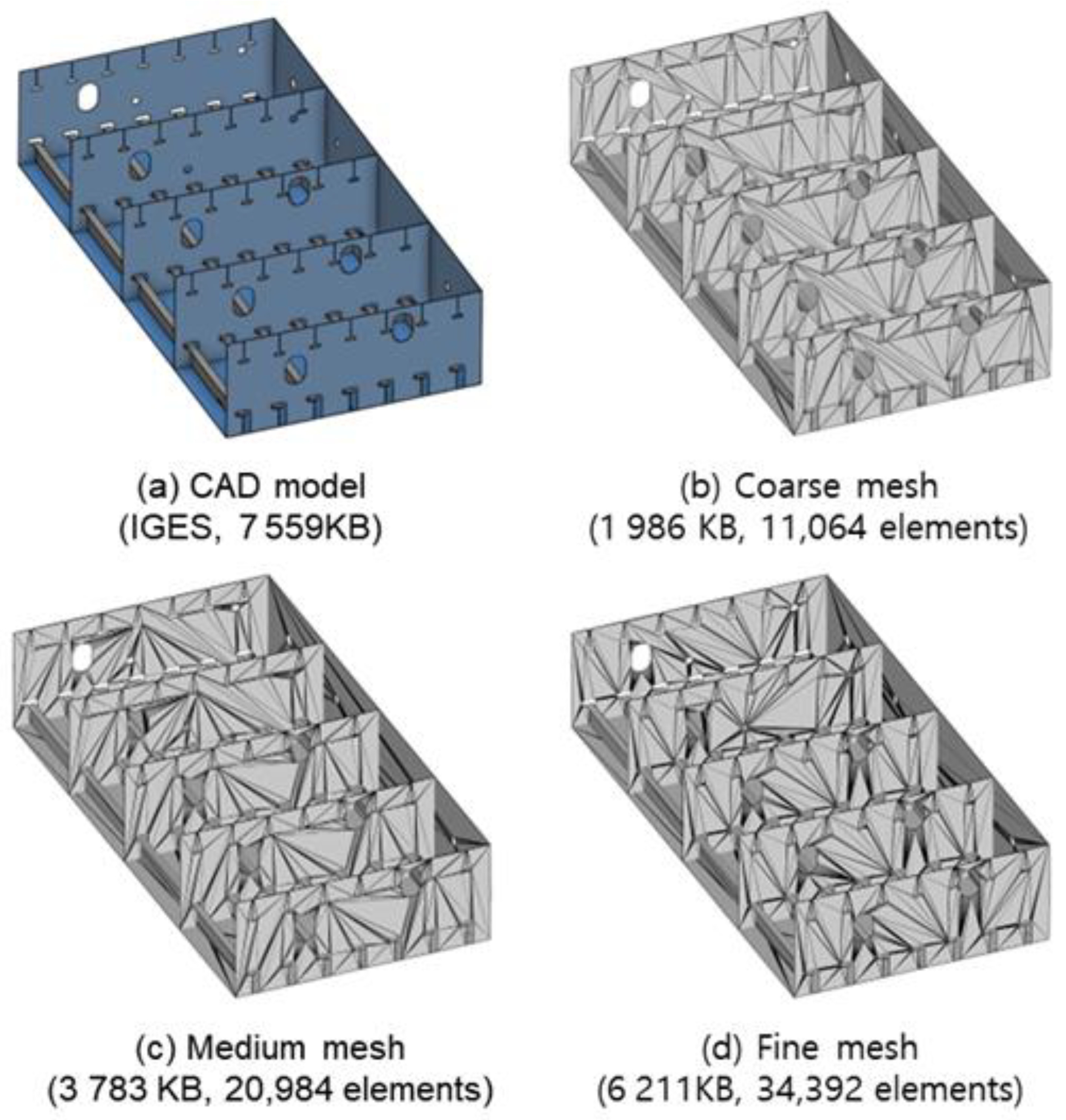
The size of the neutral CAD model file is significantly reduced in the lightweight model, which represents 3D geometry in the form of a triangular mesh. The file size varies depending on the density of the triangular mesh, as shown in
Figure 1. For example, the size of the IGES file in
Figure 1a is 7559 kB. However, if triangular meshes are tessellated from this file, smaller file sizes of 1986, 3783, and 6211 kB are obtained, as shown in
Figure 1b–d, respectively. The geometry saved in the 3D CAD model is divided into numerous triangles in the tessellation process, resulting in an increase in the data size and memory usage and a reduction in visualization performance. Therefore, in the lightweight model, a low-density triangular mesh is generated. However, this can cause errors in the boundary line segments of the lightweight model that correspond to the boundary curves in the CAD model. Thus, when generating weld lines from the lightweight model, it is important to restore the weld lines without any errors compared to the curves in the CAD model.
3. Weld Line Generation
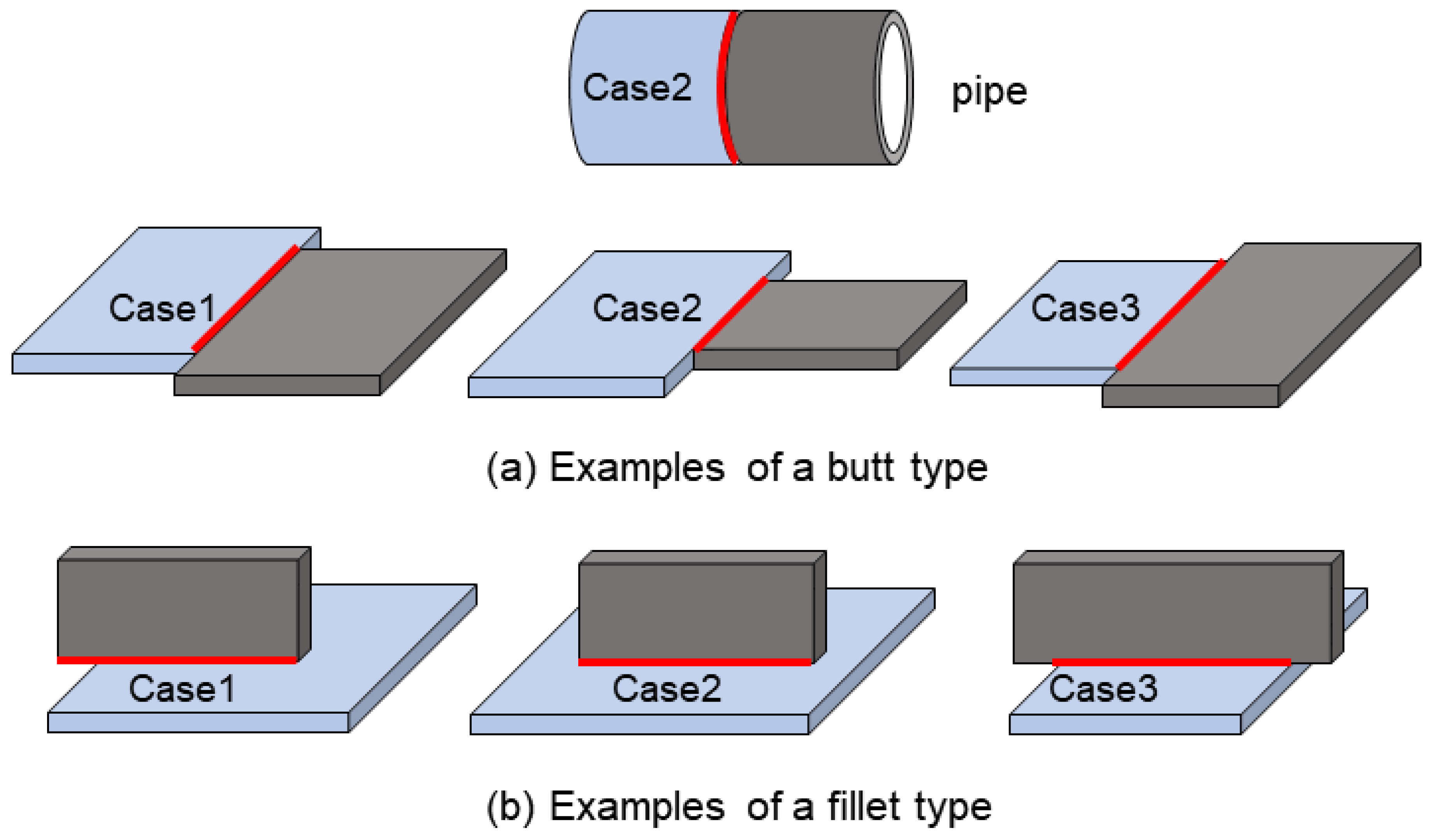
The weld joining methods commonly used in shipbuilding and offshore plant construction are classified into butt welding and fillet welding, as illustrated in
Figure 2. Butt welding involves joining two parts horizontally, while fillet welding involves joining one part on top of the other vertically. In butt welding, two parts are welded at the top and bottom sides, whereas in fillet welding, two parts are welded at both sides. Consequently, there are two weld lines in the two cases of
Figure 2. Welding takes place at the locations where two parts meet, and the two joining methods are categorized based on the angle at which the two parts intersect. The weld line corresponds to the situation where the boundary edge of a part meets the face of the adjacent part.
A ship or offshore plant structure consists of numerous blocks. A block, in turn, consists of numerous parts. The following operations are performed for each part to generate a weld line:
- (1)
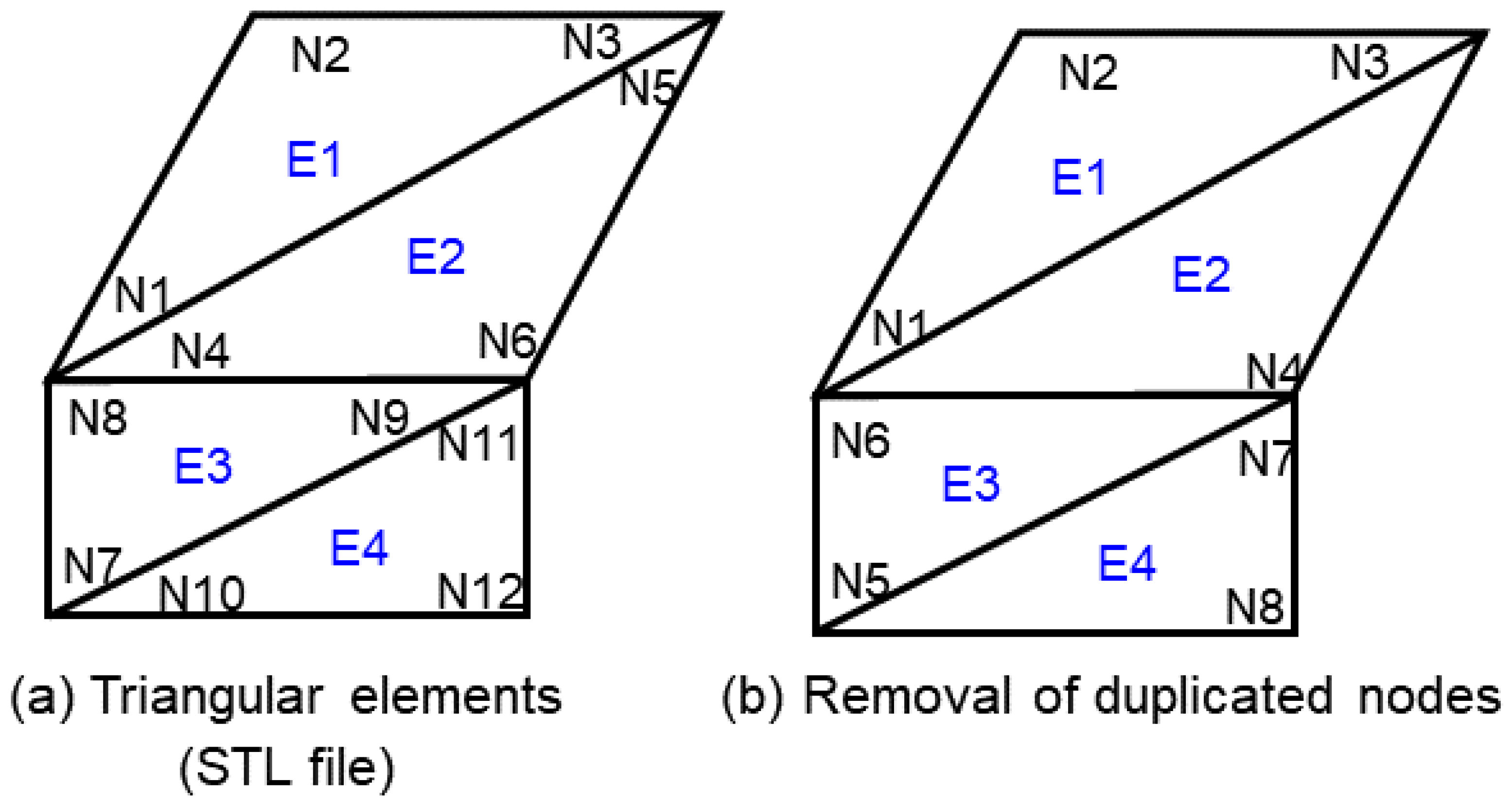
Removal of redundant (or duplicated) nodes: If there are multiple nodes with the same coordinate value, only one of them is left alone while the rest are removed. The node information of the elements that reference the removed nodes is updated with the one remaining node.
- (2)
Generation of the boundary element edge: The node referenced by the element is used to generate the element edge. The angle information for the element adjacent to each element edge is calculated. If the calculated angle deviates from 180° or if there is no adjacent element in the vicinity, the element edge is classified as a boundary element edge.
- (3)
Face identification: the faces in the mesh model are identified based on the boundary edges.
- (4)
Generation of the boundary edges of a face: the boundary edges of the classified face are generated by connecting the boundary element edges.
- (5)
Generation of a weld line: if the part’s boundary edge and its adjacent part’s face intersect, the intersection line is calculated and classified as a weld line.
3.1. Redundant Node Removal and Boundary Edge Generation
In the lightweight model, there is no information on the topology between triangles. Therefore, using purely coordinate values, a distance map is constructed, and the redundant nodes are removed.
Figure 3a shows the lightweight file structure in the STL format, which is commonly used.
Figure 3b shows the result of the removal of redundant nodes: 12 nodes are reduced to 8.
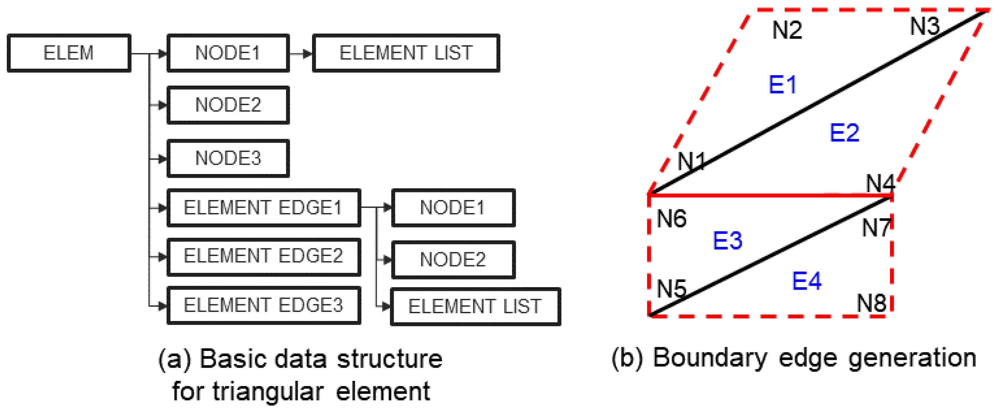
After the removal of the redundant nodes, a data structure is created, as shown in
Figure 4. The basic triangular data structure is used to represent the mesh model. An element has three nodes and three element edges. Each element’s edge has its own node and element information. For each node, the information of all adjacent elements is stored as a list. Each element’s edge also stores the information of all adjacent elements as a list. After the generation of the data structure in this manner, the angle formed by two elements for each element edge is checked to extract the boundary element edge. In
Figure 4b, the red lines show the boundary element edges identified in a mesh model. If the angle formed by an element adjacent to a particular element edge deviates significantly from 180° (as shown by the red solid line in
Figure 4b) or if there is no adjacent element, the element edge is classified as a boundary element edge (as shown by the red dotted lines in
Figure 4b).
3.2. Face Identification and Boundary Curve Generation
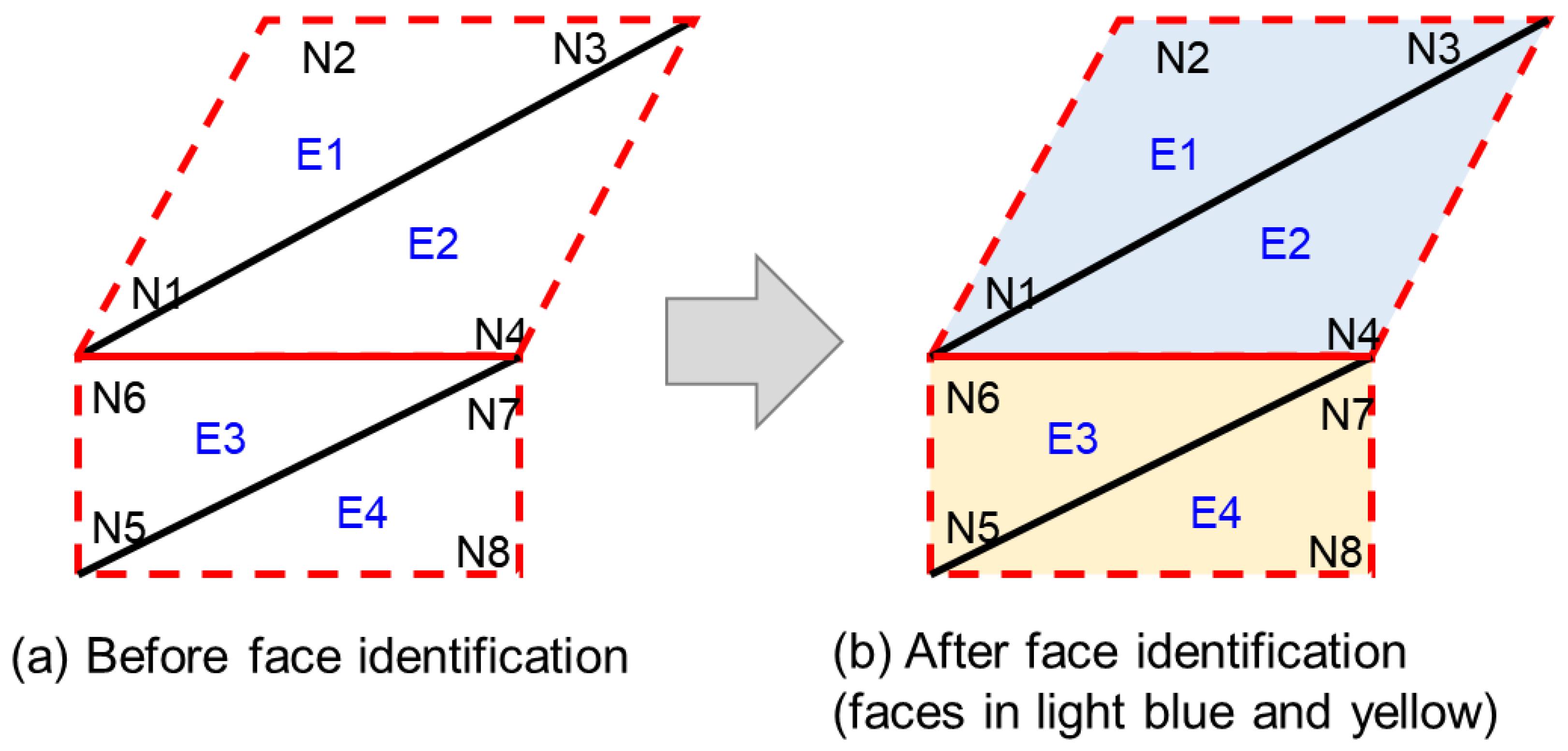
The faces of the mesh model are identified using the boundary element edges. An arbitrary element is selected, and if its element edge is not a boundary element edge, other elements adjacent to this edge are contained in the same face. This process is repeated for the non-boundary element edges of the newly contained elements in the face, and the elements to be contained in the same face are continuously expanded. In
Figure 5a, suppose that element E1 is the starting element. Element edge N1N3, among the element edges of this element, is not a boundary element edge. Therefore, E2, an element adjacent to the element edge N1N3, is contained in the same face that element E1 belongs to. As there are no more cases of non-boundary edges in element E1, E3 is chosen as a new starting element among the unchecked elements. Applying the same method shows that elements E3 and E4 are contained in the same face. Finally, two faces are identified, as shown in
Figure 5b. Boundary element edges are then generated for each identified face. For example, in the case of a face containing elements E1 and E2, the boundary element edges are element edges N1N4, N4N3, N3N2, and N2N1.
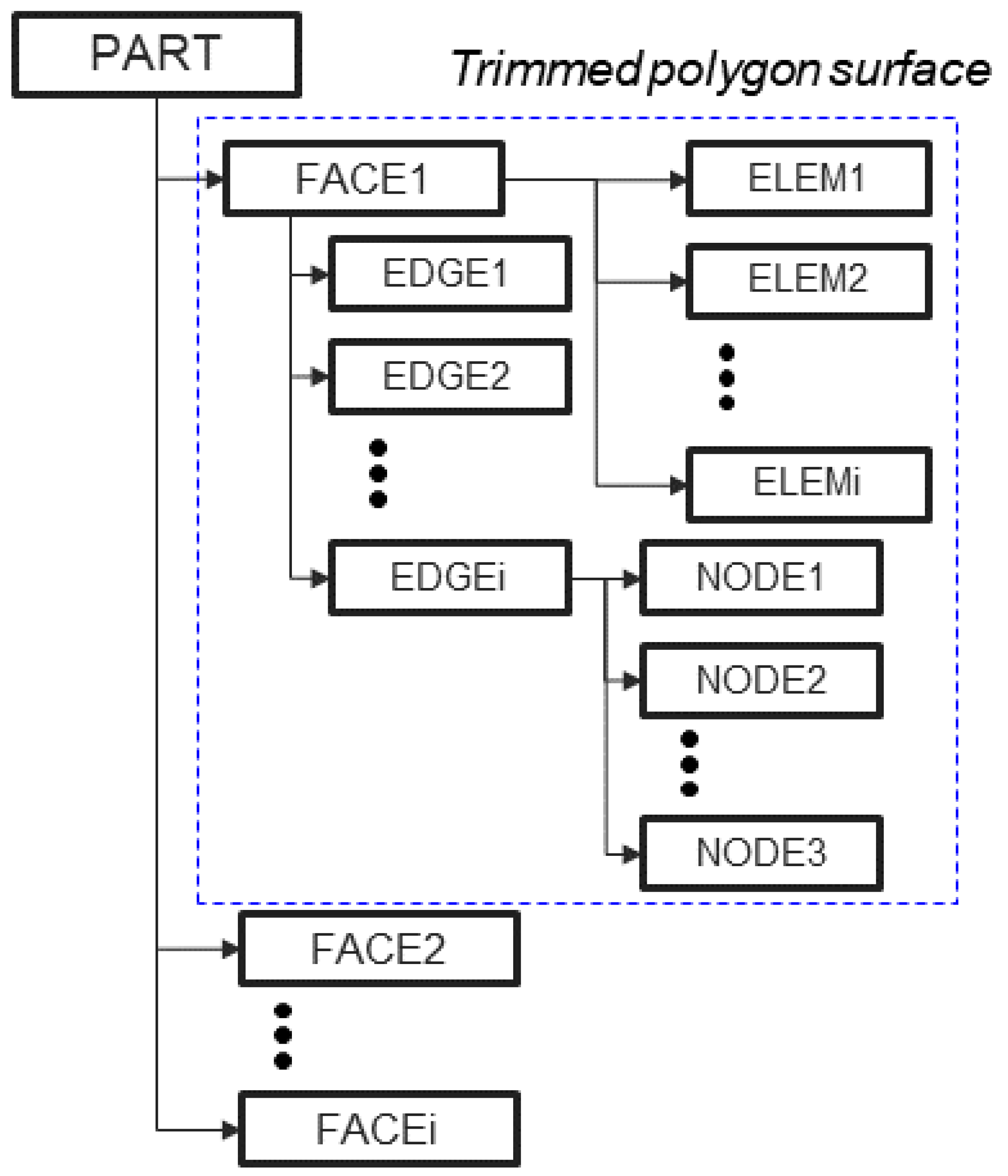
After the identification of the faces, the data structure of their parts is constructed. As shown in
Figure 6, a part has multiple faces, and each face consists of the boundary edges and elements contained in the face. The face’s geometry is not represented as a parametric function but as a set of triangular elements. Each part is represented by a boundary representation (B-rep) model surrounded by faces. Each face is represented by a trimmed polygon surface composed of a triangular element set and boundary edges.
3.3. Weld Line Generation
Welding is performed at locations where two parts meet [
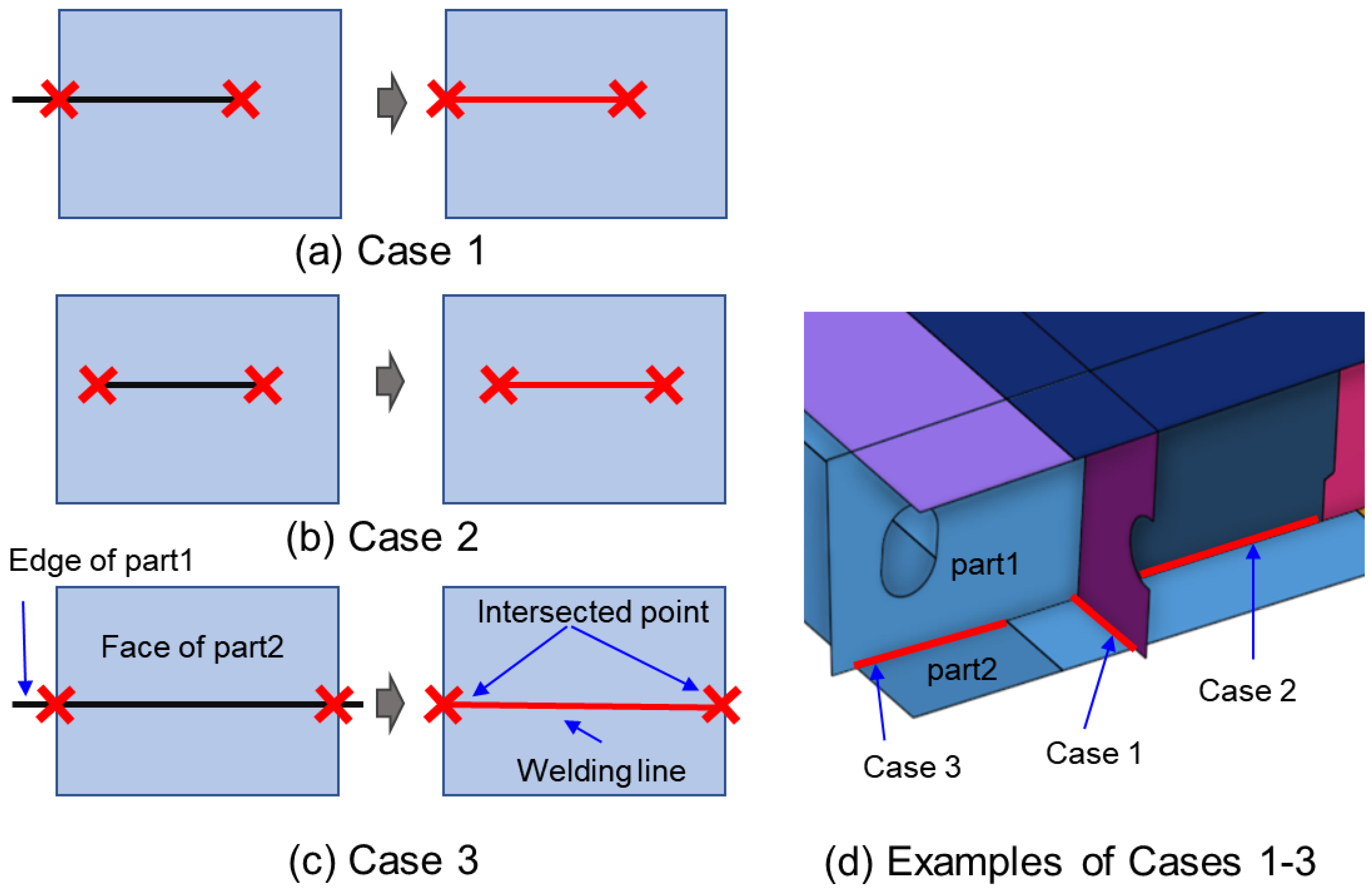
24]. Therefore, if the boundary edge of one part lies on an adjacent part, it becomes a weld line. However, checking for intersections along all boundary edges can be time-consuming. To address this, intersections are first checked accurately in minimal time by constructing a bounding box for the parts, faces, and edges. The sequence for checking for intersections is as follows: First, intersections are checked for the bounding box of the two parts that are the targets of intersection checking. If there is an intersection, it is then checked whether each face of part 1 intersects with part 2. The face of part 2 that intersects with the face of part 1 is then identified. Finally, it is checked whether an edge of part 1 intersects with the face of part 2.
In the case of the butt type, the section where two edges overlap is considered a weld line. For the fillet type, if an edge of part 1 is contained in the face of part 2, it also becomes a weld line (
Figure 2). Since the butt-type weld line is also a case where the edge is contained in the face of part 2, the same method can be applied.
Figure 7 illustrates a scenario where reinforcement is welded to a curved part. In this case, if an edge of part 1 is contained in the face of part 2, the intersection points with the edge of part 1 are determined for all edges of the face of part 2. It is then verified whether the start and end points of the edge lie on the face.
Figure 7a provides an example of weld line generation for a scenario where there is only one intersection point and one of the start or end points lie on the part.
Figure 7b provides an example of weld line generation for a scenario where both start and end points lie on the part’s face.
Figure 7c provides an example of weld line generation for a scenario where there are two intersection points. The weld line is represented as a straight line for a flat face and as a curve for a curved face. In general, two paired weld lines exist parallel to each other, and multiple weld lines may exist on one part.
Figure 7d provides an example of weld line generation for Cases 1, 2, and 3.
Figure 8 shows examples of weld line generation for butt and fillet types. Two parts mate at their boundary edges in the butt type, as shown in
Figure 8a. In the fillet type, the edge of one part is adjacent to the faces of another part, as shown in
Figure 8b. Pipe welding belongs to the butt type, precisely case 2 of
Figure 8a.
4. Application of Generated Weld Lines
The lightweight model is based on the ship coordinate system. In an assembly plant of blocks (semi blocks and large blocks), the task is performed by placing them on the floor. In general, the base plate is placed on the floor, while the direction of the longitudinal stiffener is arranged consistently. In the lightweight model, it is necessary to find the base plate and longitudinal stiffener and move their geometry according to the direction of the work floor. In other words, the lightweight model’s coordinate system must be converted from the ship coordinate system to the work coordinate system before the calculation of the bead length (welding length) and generation of the welding path.
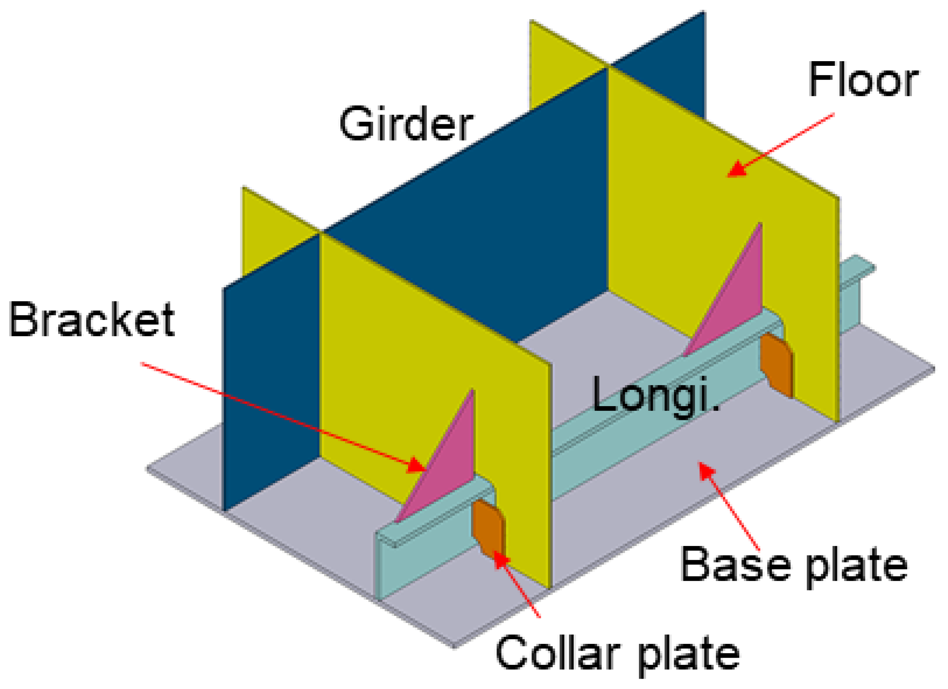
The part type is classified into a base plate, collar plate, longitudinal stiffener, girder, floor, bracket, and others, as shown in
Figure 9. The floor is a part that is perpendicular to the
x-axis based on the ship coordinate system. The
x-axis indicates the bow-and-stern direction. The girder refers to a thin plate among the bow-and-stern direction parts, while the longitudinal stiffener refers to the reinforcement in the bow-and-stern direction. The bracket is a part that reinforces the floor and longitudinal stiffener.
The work coordinate system is established by identifying one base plate and one longitudinal stiffener. Typically, the base plate is a thin plate with the largest area in the block, while the longitudinal stiffener is a part with a long length and small width. Therefore, the plane with the largest area among all parts of the block is selected as the base plate. The longitudinal stiffener is situated adjacent to the selected base plate and is identified by locating a part with a long length and small width or height using the bounding box values. Subsequently, the work coordinate system is defined by setting the longitudinal stiffener’s direction as the x-axis and the vertical direction of the base plate as the z-axis.
4.1. Bead Length Calculation for the Welding Material Quantity Estimation
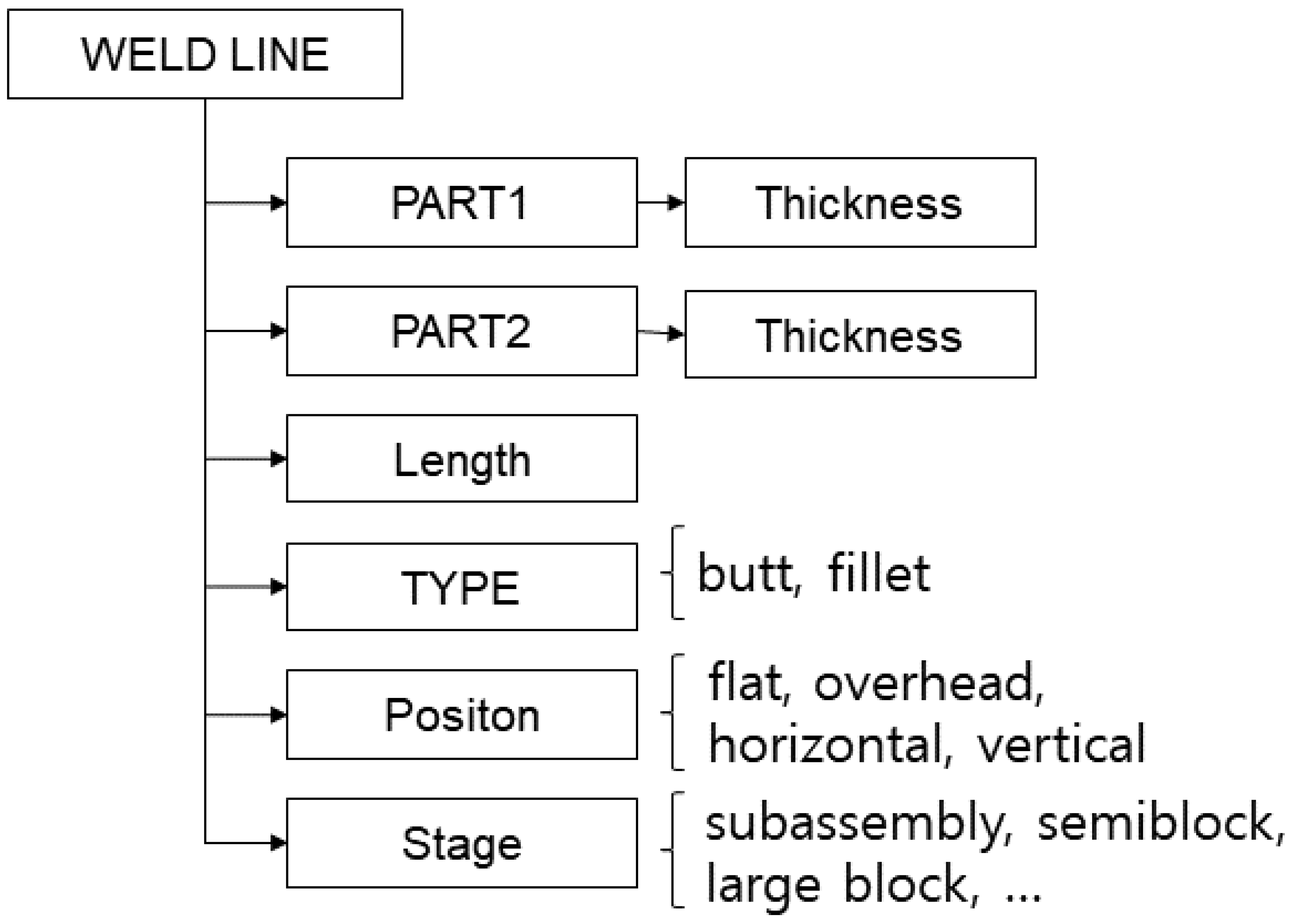
Welding material quantity estimation requires bead length and leg length. Bead length can be calculated using the weld lines after performing the procedure explained in the remainder of this section. The exact welding material quantity needs the geometry of the two parts to be welded to be identified. However, the lightweight model does not directly contain this information. Therefore, additional information is extracted, as shown in
Figure 10, from the lightweight model using the generated weld lines.
In general, a larger thickness requires a larger quantity of welding material. Thus, the thicknesses of the two parts to be welded are extracted and saved. The thickness is the distance between the two faces with the largest areas in the part. The type of welding is determined based on the position of the two parts to be welded. Fillet welding is generally performed during the process of assembling blocks, after the semi block assembly process. The level of difficulty varies depending on the welding position. In welding work, the part placed on the floor becomes the base plate, and the welding position is determined with respect to the base plate. The welding position can be classified as flat, vertical, horizontal, and overhead. Flat welding corresponds to the weld line placed parallel to the base plate. Vertical welding is performed from the bottom direction (−z) to the top direction (+z), perpendicular to the base plate. Overhead welding refers to a case where the weld line is placed at the bottom of the base plate. If the above three positions do not apply, it becomes horizontal welding.
4.2. Path Planning for Welding Automation
In automatic welding, a welding path is generated, and then a robot performs the welding by following this path. The method for generating the welding path required for automatic welding is as follows:
- (1)
Part type classification: the shape and direction information of the part are used to classify the part type.
- (2)
Cell generation and weld line classification: The working radius of the welding robot is limited. After generating the subsections (cells) where the robot can perform the task after its installation, the lightweight model is divided based on the subsections. The weld line is then classified for each subsection.
Each part’s type is determined by the following method: The candidate type is specified according to the direction. The normal direction of the face with the largest area in the part is used to primarily classify the type. If the normal direction is the x-axis, the part type is a collar plate and floor. If the normal direction is the y-axis, it is a longitudinal stiffener, girder, and bracket. If the normal direction is the z-axis, it is a base plate.
After the primary classification, the final part type is specified by checking whether each part satisfies a set of conditions. Here, the area refers to the value of the largest face of the part. The base plate, must have a small thickness and a large area, with the bounding box located at the lowest position. For the floor and girder, the thickness must be small, and the bottom plane of the bounding box must be close to the base plate. Furthermore, they must be high in the height direction. The longitudinal stiffener must have a bounding box in which the bottom plane is close to the base plate while being short in the height direction and long in the x-direction. The bracket must have a small thickness and area, while the bottom plane of the bounding box is off the base plate. Moreover, the bracket must be placed on the longitudinal stiffener. The collar plate must have a small thickness and area. The bottom plane of the bounding box must not be too far from the base plate, and the top plane must not be too high. All parts that do not satisfy the above conditions are classified as other parts. The user may change them as needed to perform the task.
The result of the classification of the part types for a block consisting of 177 parts, as shown in
Figure 11a, is presented in
Figure 11b. There were 4 base plates, 29 floors, 4 girders, 11 longitudinal stiffeners, 24 collar plates, 31 brackets, and 75 other parts classified.
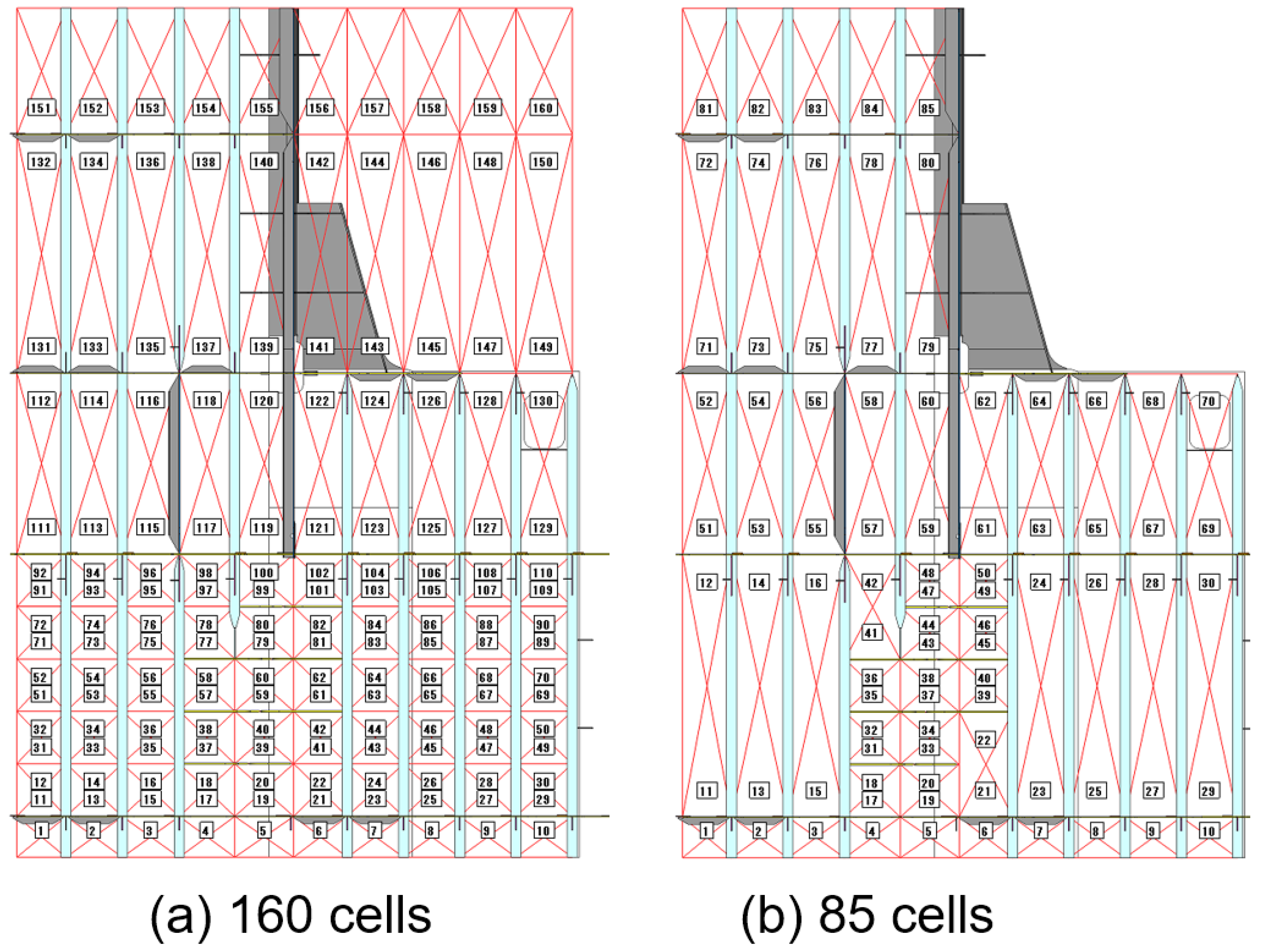
A subsection where a robot performs welding after installation is referred to as a cell; it is distinguished by the floor and longitudinal stiffener or girder as the boundary. Cell generation is performed using the following method: First, the face placed on the base plate is identified for the floor, girder, and longitudinal stiffener. A centerline is generated for each face, and these centerlines are connected to form a line for the same structural member. In the case of a floor, multiple lines can be generated due to slot holes. All intersection points of the girder, longitudinal stiffener, and floor are calculated, and if the length is too small, it is extended to proceed with the calculation. Cells are generated as many as (number of girders + longitudinal stiffeners) × number of floors × 2. A cell is rectangular in shape, but it may not be rectangular if the member is tilted. If the workspace is divided into multiple cells, they can be merged as long as they can be worked on simultaneously. Lower or upper cells are merged if there is no floor between them and left or right cells are merged if there is no longitudinal stiffener or girder.
Figure 12 shows the result of cell generation. With 10 girders and longitudinal stiffeners and 8 floors, 160 cells were generated in total (
Figure 12a). Cells without floors were merged, and those without structural members were excluded, resulting in the generation of 85 cells (
Figure 12b). After the cells are generated, the weld lines are grouped based on the cells.
5. Experiments
A prototype system was implemented according to the proposed method, and experiments were performed for several test cases. The hardware used in the experiments was a Windows OS-based personal computer equipped with an i9-12900K CPU, 64 GB of memory, and an SSD M.2 NVMe storage device. Visual Studio 2019 (C++) was used as the development tool.
Figure 13 shows the result of the generation of weld lines for a curved-part geometry. A lightweight model (
Figure 13b) was generated from a CAD model (
Figure 13a) to determine the accuracy of weld line generation. In the geometry, 14 reinforcements are mounted on one curved part, and 32 weld lines were generated. Two butt-type weld lines were generated at the places where the two curved parts met, and 30 fillet-type weld lines were generated at the places where the reinforcements and curved parts met. All of these cases correspond to flat welding. The bead length (welding length) was 35,622.02 mm, while the length calculated by the actual CAD data was 35,623.83 mm. The calculation lasted 0.02 s. An error of 1.61 mm occurred in the calculation of the length of the boundary edges by interpolating the nodes of the lightweight model. This shows that the length of the weld lines was calculated very accurately.
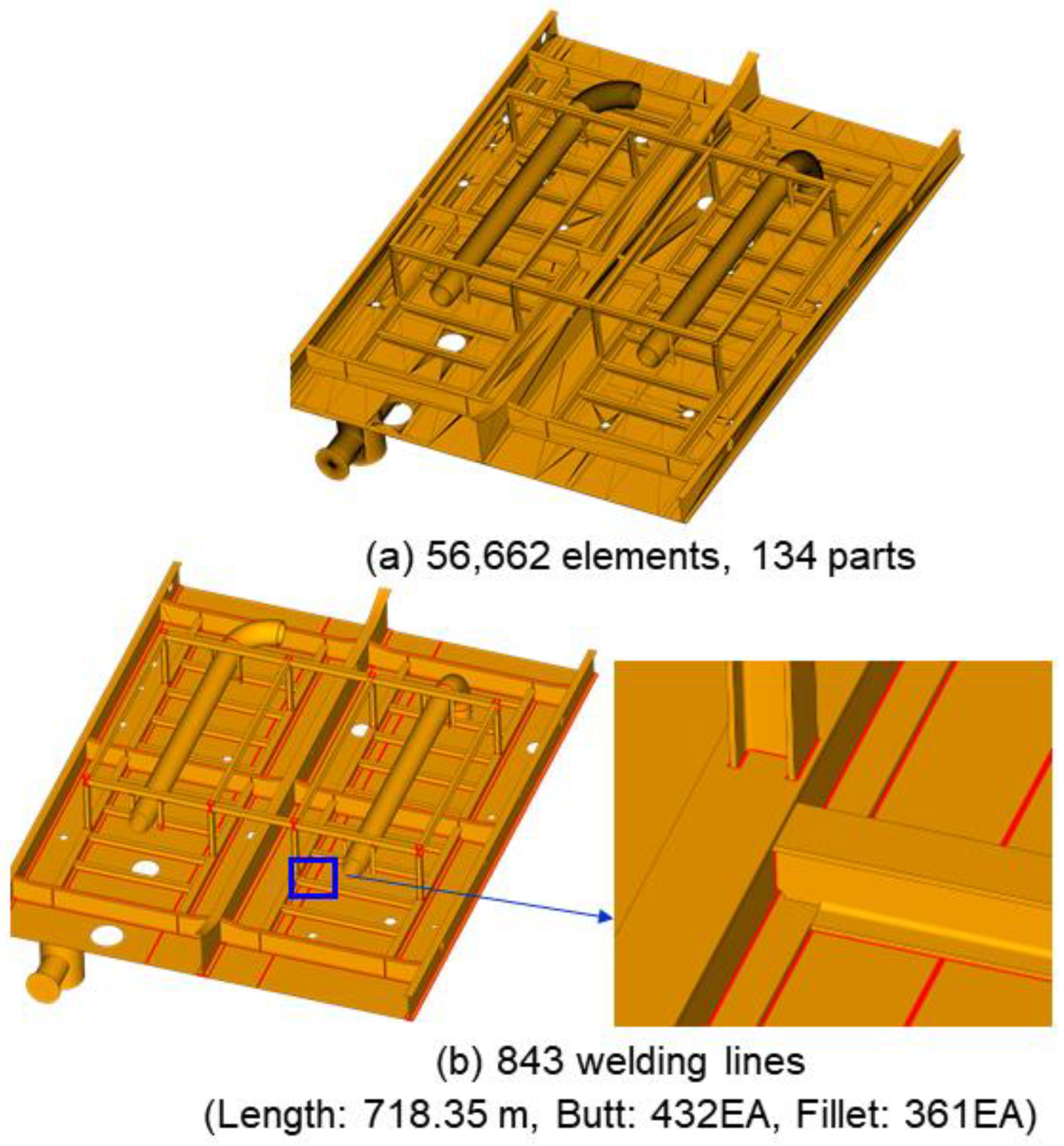
Figure 14 shows the result of the generation of the weld lines for a block. The block consists of 56,662 triangles and 134 parts. 843 weld lines were generated in this block. The total bead length (welding length) was 718.35 m, while the total time required to generate the weld lines was 0.25 s. Butt-type weld lines were generated for piping. The weld lines were properly generated at all places where the parts met.
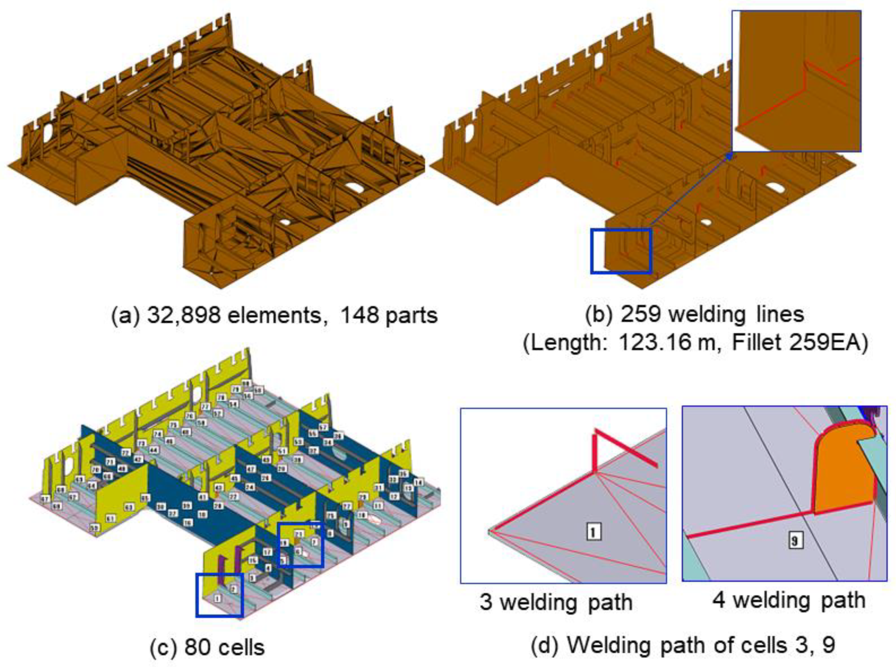
Figure 15 depicts an example of automatic welding path generation. The semi block of a ship (
Figure 15a) consists of 32,898 triangles and 148 parts. For a preliminary welding process, only the weld lines corresponding to the work process need to be generated.
Figure 15b illustrates the generation of 259 weld lines for fillet welding, with a total length of 123.16 m and a required time of 0.67 s. The weld lines were generated for all places where members meet, except for those used in the subassembly. Work in the subassembly is determined by the member type. For instance, the base plate and longitudinal stiffener were already worked on in the previous process. In the current process, work is performed at the junction of the floor and longitudinal stiffener.
Figure 15c shows the 80 generated cells.
Figure 15d displays the weld lines generated for Cells 3 and 9.
The welding lines in this study were generated from the lightweight model without considering the distortions and bending occurring in structures. As a result, the weld lines generated by the proposed method may differ partially from those used in the field. To address this issue, welding robots can be equipped with measuring devices such as touch sensors to adjust weld positions if necessary.
6. Conclusions
A method of generating weld lines based on a lightweight model instead of a 3D CAD model is proposed. The generated weld lines are then used to calculate the bead length for welding material quantity estimation and to plan welding paths. The process involves removing redundant nodes, generating boundary edges, identifying faces, generating boundary curves for the faces, and extracting the weld lines to generate the weld lines from the lightweight model. Before calculating the bead length and generating welding paths, the coordinate system of the lightweight model is converted from the ship coordinate system to the work coordinate system. Information such as welding type, welding thickness, welding length, and welding position is extracted to calculate the bead length for welding material quantity estimation. Finally, after classifying the part types and generating the cells (subsections), the weld lines contained in each cell are classified and used to perform welding path planning. Experiments on various test cases confirm that weld line generation, bead length calculation, and welding path generation can be performed accurately in a short time of approximately 1 s.
The proposed method is timely and can improve the utilization of lightweight models, given that most shipyards have been using them in recent years. Additionally, it offers a solution for cases where weld line information is missing from the 3D CAD model. To the best of our knowledge, this is the first study to utilize lightweight models to support the welding process in shipyards.
Future work includes investigating the estimation of welding material quantities for each manufacturing stage to facilitate accurate distribution and scheduling of welding tasks for workers, as well as the automatic generation of welding robot paths. Furthermore, since the welding position varies based on the geometry of the block in the work process rather than the design coordinate system, the algorithm that automatically specifies the basic parts will need enhancement.
Author Contributions
Conceptualization, K.K.; methodology, K.K.; software, K.K.; data curation, K.K., J.L. and D.M.; writing—original draft preparation, D.M.; writing—review and editing, J.L. and D.M.; funding acquisition, K.K. and D.M. All authors have read and agreed to the published version of the manuscript.
Funding
This research was supported by the Basic Science Research Program [NRF-2022R1A2C2005879, 2021R1F1A104817211] through the National Research Foundation of Korea funded by the Korean government (MSIT), by the AI-based gasoil plant O&M Core Technology Development Program [21ATOG-C161932-01] funded by the Korean government (MOLIT), and by the Nuclear Power Plant Dismantling Safety Reinforcement Convergence Core Technology Development Program [RS-2022-00155255] through the National Research Foundation of Korea (NRF) funded by the Korean government (MSIT).
Institutional Review Board Statement
Not applicable.
Informed Consent Statement
Not applicable.
Conflicts of Interest
The authors declare no conflict of interest.
References
- Posada, J.; Toro, C.; Barandiaran, I.; Oyarzun, D.; Stricker, D.; de Amicis, R.; Pinto, E.; Eisert, P.; Döllner, J.; Vallarino, I. Visual computing as a key enabling technology for industrie 4.0 and industrial internet. IEEE Comput. Graph. Appl. 2015, 35, 26–40. [Google Scholar] [CrossRef]
- Zissis, D.; Lekkas, D.; Azariadis, P.; Papanikos, P.; Xidias, E. Collaborative CAD/CAE as a cloud service. Int. J. Syst. Sci. Oper. Logist. 2017, 4, 339–355. [Google Scholar] [CrossRef]
- Kang, Y.; Kim, B.; Mun, D.; Han, S. Method to simplify ship outfitting and offshore plant equipment three-dimensional (3-D) computer-aided design (CAD) data for construction of an equipment catalog. J. Mar. Sci. Technol. 2014, 19, 185–196. [Google Scholar] [CrossRef]
- Liu, W.; Zhou, X.; Zhang, X.; Niu, Q. Three-dimensional (3D) CAD model lightweight scheme for large-scale assembly and simulation. Int. J. Comp. Integr. Manuf. 2015, 28, 520–533. [Google Scholar] [CrossRef]
- Kwon, K. Design point generation method from a lightweight model for dimensional quality management in shipbuilding. J. Ship Prod. Des. 2019, 35, 353–363. [Google Scholar] [CrossRef]
- Lee, H.; Noh, C.; Kim, S.; Kim, B.C.; Park, J.; Mun, D.; Han, S. Neutral model-based interfacing of 3D design to support collaborative project management in the process plant industry. J. Comput. Des. Eng. 2021, 8, 824–835. [Google Scholar] [CrossRef]
- Ball, A.; Ding, L.; Patel, M. Lightweight formats for product model data exchange and preservation. In Proceedings of the PV 2007 Conference, Weßling, Germany, 9–11 October 2007; pp. 9–11. [Google Scholar]
- Ding, L.; Ball, A. Product representation in lightweight formats in product lifecycle management. In Proceedings of the 4th International Conference on Digital Enterprise Technology, Bath, UK, 19–21 September 2007. [Google Scholar]
- Song, I.; Chung, S. Data format and browser of lightweight CAD files for dimensional verification over the internet. J. Mech. Sci. Technol. 2009, 23, 1278–1288. [Google Scholar] [CrossRef]
- Kwon, K.; Mun, D. Part recognition-based simplification of triangular mesh models for ships and plants. Int. J. Adv. Manuf. Technol. 2019, 105, 1329–1342. [Google Scholar] [CrossRef]
- Kwon, K.; Mun, D. A method to minimize the data size of a lightweight model for ship and offshore plant structure using part characteristics. J. Mar. Sci. Eng. 2020, 8, 763. [Google Scholar] [CrossRef]
- Back, M.; Lee, D.; Shin, J.; Woo, J. A study for production simulation model generation system based on data model at a shipyard. Int. J. Nav. Archit. Ocean Eng. 2016, 8, 496–510. [Google Scholar] [CrossRef]
- Sheen, D.; Kim, T. Block assembly planning in shipbuilding using case-based reasoning. Expert. Syst. Appl. 2007, 32, 245–253. [Google Scholar]
- Iwankowicz, R. An efficient evolutionary method of assembly sequence planning for shipbuilding industry. Assem. Autom. 2016, 36, 60–71. [Google Scholar] [CrossRef]
- Okubo, Y.; Mitsuyuki, T. Ship Production Planning Using Shipbuilding System Modeling and Discrete Time Process Simulation. J. Mar. Sci. Eng. 2022, 10, 176. [Google Scholar] [CrossRef]
- Hur, M.; Lee, S.; Kim, B.; Cho, S.; Lee, D.; Lee, D. A study on the man-hour prediction system for shipbuilding. J. Intell. Manuf. 2015, 26, 1267–1279. [Google Scholar] [CrossRef]
- Ruy, W.; Kim, H.; Cho, Y.; Ko, D. Implementation of welding material quantity evaluation system combined with ship design CAD system. Int. J. Nav. Archit. Ocean Eng. 2017, 9, 219–226. [Google Scholar] [CrossRef]
- Lee, J.; Byun, S.; Nam, J.; Kang, T. Estimation of welding material quantity for shipbuilding at early design stage based on three-dimensional geometric information. J. Soc. Nav. Archit. Korea 2017, 54, 57–62. [Google Scholar] [CrossRef]
- Gao, F.; Ge, Y.; Lu, S.; Zhang, Y.; Xiao, G. Estimation of the welding material amount: Modelling and knowledgeabling. Int. J. Comp. Integr. Manuf. 2018, 31, 933–941. [Google Scholar] [CrossRef]
- Choi, W.; Kim, D.; Nam, J.; Kim, M.; Son, Y. Estimating production metric for ship assembly based on geometric and production information of ship block model. J. Mar. Sci. Eng. 2021, 9, 39. [Google Scholar] [CrossRef]
- Heo, H.; Chung, H. Stochastic assessment considering process variation for impact of welding shrinkage on cost of ship production. Int. J. Prod. Res. 2014, 52, 6076–6091. [Google Scholar] [CrossRef]
- Lee, J.; Chung, H. Modified equivalent load method for welding distortion analysis. J. Mar. Sci. Eng. 2020, 8, 794. [Google Scholar] [CrossRef]
- Lee, J.; Perrera, D.; Chung, H. Multi-Pass Welding Distortion Analysis Using Layered Shell Elements Based on Inherent Strain. J. Mar. Sci. Eng. 2021, 9, 632. [Google Scholar] [CrossRef]
- Son, Y.B.; Nam, J.H. Creation of hierarchical structure for computerized ship block model based on interconnection relationship of structural members and shipyard environment. Int. J. Nav. Archit. Ocean Eng. 2022, 14, 100455. [Google Scholar] [CrossRef]
| Disclaimer/Publisher’s Note: The statements, opinions and data contained in all publications are solely those of the individual author(s) and contributor(s) and not of MDPI and/or the editor(s). MDPI and/or the editor(s) disclaim responsibility for any injury to people or property resulting from any ideas, methods, instructions or products referred to in the content. |
© 2023 by the authors. Licensee MDPI, Basel, Switzerland. This article is an open access article distributed under the terms and conditions of the Creative Commons Attribution (CC BY) license (https://creativecommons.org/licenses/by/4.0/).
