Abstract
The prevailing offshore field development solutions, i.e., dry tree and wet tree systems, are confronted with serious technical and economic challenges in deep and ultra-deep waters resulting from the large depth of water, far offshore distance, and harsh ocean environmental conditions, as well as high cost. In response to these challenges, an innovative Deepwater Artificial Seabed (DAS) production system is proposed in this article. The DAS production system concentrates on well access and riser design, which enables shallow-water-rated subsea production systems to develop Deepwater (DW) and Ultra-Deepwater (UDW) fields. First, DW & UDW field development drivers are discussed and presented. This is followed by a detailed discussion of the merits and demerits of the prevailing dry tree and wet tree field development solutions. On this basis, the design philosophy and main characteristics of the DAS production system are presented and discussed in detail. Dynamic survival analysis for the fully coupled Floating Production Storage and Offloading (FPSO)-DAS production system is carried out. The artificial seabed stability is systematically investigated for both intact and damaged conditions. The global analysis results indicate that the DAS production system as developed experiences quasi-static responses even under extreme storm conditions, due to the location of the artificial seabed and the decoupling effects of the flexible jumpers. The new DAS production system is considered to be a competitive and cost-effective field development solution in depths of up to 3000 m.
1. Introduction
1.1. Background
In the last thirty years, the offshore petroleum industry has accelerated its capabilities of offshore petroleum production activities operating at depth, rising from approximately 500 m to 3000 m, as depicted in Figure 1. Deepwater production contributed more than 10 million Barrels of Oil Equivalent (BOE) per day in 2019 and is expected to reach 14.5 million by 2025 [1].
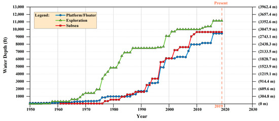
Figure 1.
Progression of water depth capabilities for offshore production activities [2].
Currently, offshore petroleum fields in deepwater (DW) and ultra-deepwater (UDW) regions are developed in accordance with either the dry tree or wet tree system, or their combination. Correspondingly, Floating Host Facility (FHF) development has evolved into four major types, covering the Tension Leg Platform (TLP), the Spar Platform, the Semi-submersible Platform, and the Floating Production Storage and Offloading (FPSO) vessel. It can be noted that each type of FHF has various degrees of flexibility in shape/design for optimization in the face of DW and UDW challenges.
In recent years, aiming to better respond to the challenges of field developments in deep and ultra-deep waters, various new types of offshore platforms have appeared in succession.
Srinivasan et al. [3] designed a Truss-pontoon Semisubmersible Platform (TSP) with heave plates, which utilized a simple open-truss structure instead of the conventional shell-pontoon to reduce wave excitation forces. Following this design scheme, the TSP was considered to be cost-effective and operationally efficient with minimum downtime. Another new concept of the Semi-submersible Platform, termed the Minimum Deepwater Operating Concept (Min Doc) [4], was developed with a concise design of three stand columns, of which the motion characteristics were more approximate to those of a Spar Platform. An Extendable Draft Platform (EDP) [5] was designed by Technip as an offshore oil and gas drilling and production platform, where the conventional pontoon of a Semi-submersible Platform was replaced by an adjustable heave plate. Other novel Semi-submersible Platforms, such as the Octabuoy [6], the Deepwater Tumbler Platform (DTP) [7], and the Multi-Body Semi-submersible Platform [8,9], were subsequently developed. A new concept of Spar Platform, called the Geometric Spar (G-Spar) [10], was proposed by Novellent Offshore LLC. The innovations of this concept primarily lay in two aspects: The cylindrical deep draft caisson of a classical Spar was replaced by an octagonal cross-section. In addition, a single, submerged buoyant hull was employed instead of individual buoyancy cans. Zhang et al. proposed a new Cell-Truss Spar Platform (CT-Spar) [11]. With the applied open-truss structure and heave plates, the CT-Spar exhibited a satisfactory performance of the heave motion and possessed a relatively small drag coefficient in the horizontal direction. Other new concepts of the Spar platform, such as the Deep Draft Multi-Spar platform (DDMS) [12], the T-Cell Spar [13], and the Slender-Spar Platform [14,15], etc., were also proposed successively. The first mono-column type platform of the FPSO vessel, named the Sevan platform [16], was designed by Sevan Marine, of which the non-directional characteristics of motion behaviors, low capital expenditure for construction, and ease of installation compared with ship-shaped FPSOs were attractive, and thus it was considered a unique and promising concept in the industry. Based on the design scheme of the Sevan platform, a new FPSO vessel, called the SSP320 platform [17], was developed with reduced vortex-induced motion and improved heave motion.
In addition, several kinds of new riser systems were developed. The Free-Standing Hybrid Riser (FSHR) [18,19], originating in the 1980s, combined the utilization of steel pipes tensioned by freestanding buoyancy cans and flexible jumpers for connections to the FHF, of which the typical design schemes include the Single Line Offset Riser (SLOR), the Concentric Offset Riser (COR), the Bundle Hybrid Offset Riser (BHOR), and the Hybrid Riser Tower (HRT). Another novel concept of the riser system, the Buoy for Supporting Risers (BSR) system [20,21], consisting of a submerged buoy, steel catenary risers, and flexible jumpers, was designed by Subsea 7. Due to the design philosophy, the steel catenary risers were decoupled from the motion responses of the FHF.
It can be seen that with respect to the assessment of development options for a new offshore petroleum field, the type and design scheme of the FHF are concentrated on, while the well access and riser design issues are ignored [22].
However, it has been recognized that the prevailing offshore field development solutions provide distinct merits and demerits in DW and UDW regions due to their own inherent design and operational philosophies. The dry tree development solution allows for Direct Vertical Access (DVA) to the wells for drilling, workover, as well as improved recovery, but requires an optimized FHF hull for motion responses to fit the top tensioned riser system. This is deemed to be restrictive in terms of water depth and flexibility of field development. Though the dry tree system has been extensively applied in shallow-water field developments and the offshore petroleum industry has demonstrated a strong preference for extrapolating this field-proven solution, the dry tree development solution is not considered a feasible or optimal way to develop DW and UDW fields. The wet tree development solution is fit for widespread and dispersed reservoirs and is able to provide flexibility in field expansion and FHF selection due to the simplified well/riser interfaces but at the sacrifice of the high flow assurance requirements as well as the high drilling and workover costs because of the use of the independent Mobile Offshore Drilling Unit (MODU).
1.2. Development Drivers in DW and UDW Fields
The dominating driver in the development of offshore petroleum fields is invariably cost. The high Capital Expenditures (CAPEX) and Operating Expenditures (OPEX) for DW & UDW fields call for large oil and gas reserves, which further indicates that a large number of wells are required to maximize the recovery. Normally, reserves lower than 100 million BOE are considered marginal in UDW fields, provided that one stand-alone FHF is required [22].
Based on insights from various DW projects, key DW & UDW development drivers are presented as follows.
- Drilling CAPEX: is it possible to drill from the FHF?
- FHF CAPEX: is a motion-optimized FHF required?
- OPEX: is it possible to maintain the wells from FHF?
- Offshore construction costs: is a heavy lift required?
- Development flexibility: is it flexible for future wells? Is it flexible to accommodate an Early Production System (EPS)?
- FHF/riser interface: is it possible to simplify the interaction between FHF and riser?
- FHF flexibility: Does the riser system impact FHF requirements?
- Fatality risk: is the well bay close to personnel?
- Flow assurance management: are long tie flowlines required?
- Technology gap: is the technical threshold high?
It should be noted that the technology gap is a key development driver for developing countries, as most offshore oil and gas companies in developing countries do not possess their own core technologies for DW & UDW field developments.
1.3. Objectives of This Work
To overcome the serious technical and economic challenges to oil and gas exploitation in deep and ultra-deep waters, resulting from large water depths, far offshore distance, harsh ocean environmental conditions [23] as well as high CAPEX and OPEX, the authors argue that a radical change in field development solutions should place importance on key ‘enabling’ technologies of the well and riser systems. Given this, the objective of this paper is to present an innovative DAS production system [24,25,26,27] with the utilization of shallow-water-rated subsea production systems, as a radical and optimized approach to cost-effective oil and gas field development in deep and ultra-deep waters. In addition, this paper carries out dynamic survival analysis for the fully coupled FPSO-DAS production system, and systematically investigates the artificial seabed stability for both intact and damaged conditions.
1.4. Structure of This Paper
The paper is organized as follows. The detailed merits and demerits of the dry tree and wet tree systems are presented and discussed in Section 2. The design philosophy and main characteristics of the DAS production system are also presented in this section. In Section 3, dynamic survival analysis for the fully coupled FPSO-DAS production system is carried out and the artificial seabed stability is systematically investigated. Finally, the conclusions are presented in Section 4.
2. The Proposed DAS Production System for DW and UDW Developments
2.1. Design Philosophy of the Offshore Field Development
2.1.1. Dry Tree System
Figure 2 shows the trend of DW & UDW field developments using dry tree systems. It should be noted that not all TLPs and Spar Platforms are dry tree systems, as some subsea field developments adopt the TLP or Spar Platform as the host facility, such as Perdido in the Gulf of Mexico (GoM).
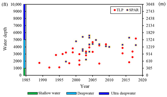
Figure 2.
Summary of worldwide dry tree systems.
The generic schemes of the dry tree system are shown in Figure 3 and Figure 4 [28] and the key features of this scheme can be summarized as follows:
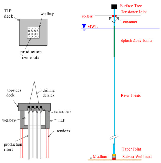
Figure 3.
Plan and elevation views of the dry tree system (TLP) [22].
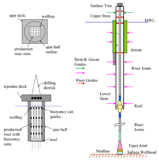
Figure 4.
Plan and elevation views of the dry tree system (Spar) [22].
- Location of the X-mas trees at the surface
- Use of a TLP or Spar platform-type facility
- Use of the Top Tensioned Risers (TTRs)
The principal benefit of dry tree systems is the direct access to surface trees for production control and direct vertical access to wells for intervention activities. In particular, the expensive MODU can be replaced by the dry tree system equipped with the drilling equipment. A second important benefit is the minimal flow length from the reservoir to the FHF, which contributes to preventing wax and hydrate conditions, thus ensuring flow assurance.
For developments with high well count or deep and complex reservoirs, dry tree systems equipped with a drilling rig are able to reduce drilling and workover costs by avoiding the need for a high-cost MODU. A second important advantage is the minimal flow length from the reservoir to the surface facility, which assists in preventing wax and hydrate conditions, thus ensuring flow assurance.
Nonetheless, the significant benefits of the dry tree system are inevitably accompanied by the following challenges:
- Limited FHF options
- Proprietary FHF designs
- High CAPEX of FHF
- High payload capacity requirements
- Water depth limitations
- Heavy lift requirement
- Limited development flexibility
- Complex FHF/riser interface
- High fatality risk
The design philosophy of both TLP and Spar concepts is to provide a stabilized platform for supporting TTRs. Therefore, the excellent motion responses of the platform, particularly the heave motion response, are required. The TLP concept achieves this by steel tendons with high pre-tension, while the Spar concept achieves this by minimizing the hydrodynamic loads in accordance with the deep hull draught. Up to now, it has been proved that the TLP concept is feasible at a depth of 5187 ft (Big Foot, 2018) while the Spar concept is feasible at a depth of 7100 ft (Lucius, 2015). Nonetheless, the TLP and Spar concepts are both regarded as fundamentally troublesome and impractical for UDW field developments.
The UDW TLP challenge is mainly due to the steel tendon design. With the increase in water depth, the steel tendons will lose the practical ability to offer the required levels of axial stiffness. In practice, the technical feasibility of the TLP concept is challenged when the depth of water exceeds 5000 ft, though some improvement works have been carried out to extend the TLP concept to operate in ultra-deep water.
The UDW Spar challenge is mainly due to the increased weight of TTRs with the increase in water depth, especially for the dual-casing riser systems, which call for large Aircan Riser Tensioners (ARTs) by increasing their length or diameter. As shown in Figure 4, the ARTs are located inside the Spar hull to minimize the hydrodynamic loads from surface waves and currents. In consideration of the handling and installation activities, the ART length is limited to approximately 230 ft. Given this, an increase in the ART diameter is the only feasible way to meet the large tension requirements. However, a substantial ART diameter will naturally increase the wellbay spacing. Hence, a broad hull is required by the UDW Spar concept.
Aiming to overcome the demanding limitations of ARTs on the Spar concept, Hydro-Pneumatic Tensioners (HPTs) are recommended. Though HPTs simplify the interface between the Spar hull and TTRs, the following challenges can be expected.
- The payload of the Spar hull is increased as a result of coupled HPTs;
- The large stroke of HPTs is required as a result of the Spar offset;
- The Spar response motions are influenced as a result of the HPT stiffness;
- The fatigue damage of TTRs is increased as a result of tension fluctuations.
It can be seen that easy solutions haven’t been found to support heavy TTRs for a Spar in ultra-deep water. It can also be envisaged that even if the steel tendon problem can be solved for the UDW TLP, the heavy TTRs will still be a serious challenge. It can also be noted that both TLP and Spar systems are unable to support more TTRs in case new favorable reserves are discovered. The pre-investment of additional well slots due to reserves uncertainty will expose commercial risks. In addition, both TLP and Spar systems are unable to accommodate an EPS, which is an efficient way to reduce reservoir risks. In all, it is critical to reasonably determine the number of TTRs with a view to balancing the expensive cost caused by the overestimation and the limitation for future tiebacks due to the insufficient payload capacity.
In addition, the wellbay on the TLP and Spar is close to crews on the platform, in which case loss of well integrity is a source of catastrophe risk for personnel.
Finally, it should be noted that most of the oil companies in Asia do not possess their core technologies in the design and operation of both TLP and Spar. This technology gap reduces their willingness to promote the development of TLP and Spar to some extent.
In recent years, the development of dry tree Semi-submersible Platforms is underway. The main orientation is to optimize its heave motion in order to be ‘TTR friendly’. As yet, this concept has not been proven in practice.
2.1.2. Wet Tree System
Figure 5 shows the trend of DW and UDW field developments using the wet tree system. It can be inferred that water depth is not the dominant restricting factor. The generic scheme of the wet tree system is shown in Figure 6 [29] and the key features of this scheme can be summarized as follows:
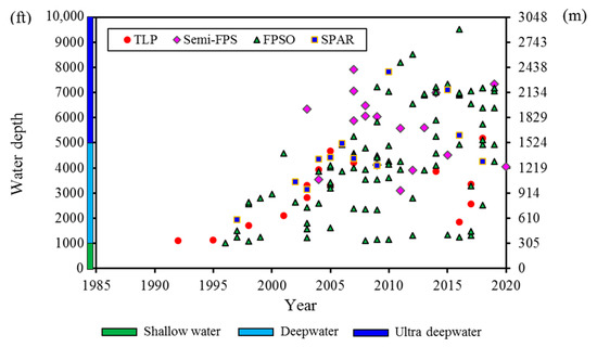
Figure 5.
Summary of worldwide wet tree systems.
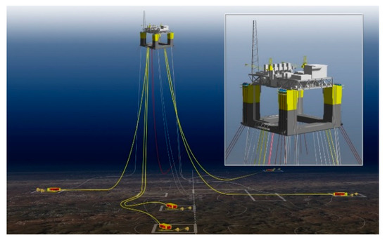
Figure 6.
The generic scheme of the wet tree system (Semi-submersible) [29].
- Location of the X-mas trees on the seabed, either in a template well arrangement or a manifold and cluster arrangement.
The principal advantages provided by the wet tree system are greater flexibility with respect to the FHF selection and field expansion capability with a simpler FHF/riser interface. Hull payload capability is also reduced to a large extent. In addition, the subsea production systems are normally offset from the FHF. Thus, their failures won’t pose a risk to crews on the FHF [30].
The challenge with the wet tree system is associated with the high drilling and workover costs as a MODU is required in most cases. A further limitation is the complex problems in relation to flow assurance as there exists a long flow path from the reservoir to the surface facility.
As yet, it should be noted that the oil companies in Asia do not possess their core technologies in the design and operation of subsea production systems, particularly in deep and ultra-deep water. This technology gap incapacitates the Asian oil companies for DW and UDW field developments by using the wet tree system independently.
2.1.3. Merits and Demerits of the Dry Tree System and the Wet Tree System
Table 1 summarizes the merits and demerits of the dry tree and wet tree systems for DW & UDW field developments. It can be found that the merits and demerits of the dry tree and wet tree development solutions are complementary. In particular, both the dry tree system and wet tree system are characterized by high technical difficulty, which will hinder the development of DW & UDW oil and gas fields in developing countries.

Table 1.
Dry tree system versus wet tree system for DW and UDW developments.
The demanding limitations of both dry tree and wet tree systems have spawned an innovative approach to cost-effective DW & UDW field developments, i.e., the DAS production system, which effectively addresses the fundamental DW & UDW field development drivers by concentrating on the critical issues of well access and riser design.
2.2. Radical DAS Production System
The generic scheme of the DAS production system is shown in Figure 7 and the key features of this scheme can be summarized as follows:
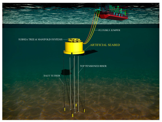
Figure 7.
DAS production system arrangement.
- Multi-body design for the artificial seabed, consisting of a Mono-Column Platform (MCP) and Internal Buoyancy Can (IBC).
- Artificial seabed installed below Mean Water Level (M.W.L) via vertical mooring tethers and TTRs respectively.
- Location of the shallow-water-rated X-mas trees and manifold on the artificial seabed.
- Individual tie-back of seabed wells to subsurface wells on the artificial seabed via TTRs.
- Individual tie-back of the manifold on the seabed to the surface facility via flexible jumpers.
The artificial seabed consists of the MCP and IBCs, which are anchored by vertical mooring tethers and TTRs, respectively. The MCP guides the IBCs and TTRs, constraining all TTRs to move collectively and thus reducing the clashing risk. The IBC provides a stable platform for holding the X-mas tree in place.
The artificial seabed is designed to position certain distances (typically 50–200 m) below M.W.L depending on the ocean environment condition, which offers three key advantages: firstly, the effects of direct loads from huge surface waves and strong surface currents can be minimized; secondly, shallow-water rated subsea production systems, such as X-mas tree, manifold, flexible jumper, etc., can be utilized; on this basis, traditional high requirements on subsea operations and maintenance can be lowered to the shallow-water rated level. In view of this, oil companies in developing countries are able to break through the development barriers of DW and UDW fields in a different way.
Connecting the artificial seabed to the surface facility, flexible jumpers, which are in a slack catenary shape, can offer the following three key economic and technical advantages: firstly, flexible jumpers can provide a high tolerance with FHF motions and make the application of a lower cost non-motion optimized FHF a reality; secondly, flexible jumpers can help to adapt the FHF location to best suit the field layout; thirdly, with a significant distance from the subsea production systems to surface installation, the risk for the crews on the surface installation is avoided induced by any failure of the subsea facilities.
With the precondition that the required subsea wells are pre-drilled, the DAS production system is then installed and in service at the field site. After that, the petroleum is channeled from the reservoir to the shallow-water-rated X-mas trees and manifold by means of TTRs and then transmitted to the FHF via flexible jumpers.
Given the above, it can be envisaged that the DAS production system, decoupled from the FHF motions and surface wave loading, is developed to exhibit quasi-static responses even under extreme storm conditions.
The wells are drilled using a combination of high/low-pressure drilling risers and the shallow-water-rated Blowout Preventer (BOP) on the artificial seabed. The subsurface BOP, by which trip time and minimum downtime can be reduced, provides efficient drilling in deep and ultra-deep waters. Well-completion is performed with ‘horizontal’ or ‘drill through’ trees that locate the tubing hanger in the tree spool. With this arrangement, it is convenient for DVA to enter the wellbore through the drilling riser or a small diameter workover riser, regardless of setting plugs and removing the X-mas tree. What’s more, the minimal flow length from the reservoir to the surface facility will benefit flow assurance requirements.
The subsurface wells are grouped in clusters around a manifold that allows 4–6 wells to be commingled, as illustrated in Figure 8. This design simplifies the FHF/riser interface to a large extent.
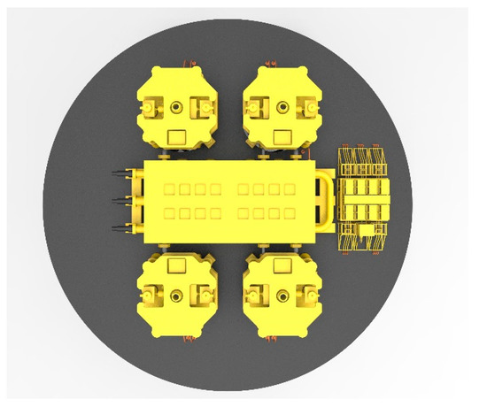
Figure 8.
Clustered wells and manifold.
The DAS production system, including the artificial seabed, subsurface well systems, manifold and flexible jumpers, can be pre-installed prior to the arrival of the FHF, which provides flexibility to the installation schedule.
It can also be noted that the single artificial seabed is able to accommodate multiple subsurface wells, which optimizes the field layout and enables large offshore field developments as well as unpredictable field expansion in the future.
In all, it can be found that the DAS production system concept considers the merits and demerits of both the dry tree system and wet tree system systematically and then overcomes the technical and economic challenges of the dry tree and wet tree systems, as tabulated in Table 2.

Table 2.
Summary of DAS production system features.
3. Case Study: Coupled Analysis of FPSO-DAS Production System
3.1. Analytic Theory
3.1.1. Equation of the Coupled Motions
The time-domain coupled motion equation for the FPSO-DAS production system can be written as [31]:
where M (p, a) is the inertia loads on the total system, M (p, v) represents the damping load of the coupled system, K(p) is the stiffness load, M (p, v, t) is the external load induced by waves and currents, p, v and a are defined as the position, velocity, and acceleration of the elements/nodes of the FPSO-DAS production system, respectively, and t refers to the current simulation time.
3.1.2. Simulation Method for Hydrodynamic Loads
In this paper, hydrodynamic loads on the artificial seabed and line structures, covering flexible jumpers, mooring lines, and rigid risers, are simulated by using an extended form of Morison’s equation, given as [32]:
where represents the induced hydrodynamic loads, refers to the fluid mass displaced by the simulated structure, denotes the acceleration of the water particle relative to the earth, and are the added mass coefficient and drag coefficient for the simulated structure, respectively, is the acceleration of the water particle relative to the structure, is the water density, is the fluid velocity of the water particle relative to the structure, and is defined as the drag area.
3.1.3. Governing Equation of the Riser System
The governing equation for the rigid riser can be expressed as [31]:
where the riser is simulated as a tensioned beam with the action of the axial tension, lateral loads, and the effects of internal and external fluids. EI is defined as the bending stiffness of the riser, Tt represents the true wall tension, pi and pe refer to the internal and external pressure around the riser, respectively, Ai and Ae are the areas of the internal cross-section and the cross-section of the rigid riser, respectively, f(z) is the lateral load per unit length on the riser, and wt, wi and we represent the weights per unit length of the rigid riser, the internal fluid in the riser, and the fluid displaced by the riser, respectively.
3.1.4. Fully Coupled Numerical Model
The feasibility and response of the DAS production system have been studied in the water depth of 3000 m in the South China Sea (SCS). The three-dimensional nonlinear analysis program Orcaflex [32] is employed for the global static and dynamic analyses of the DAS production system. The nonlinear coupled dynamic analysis model of the FPSO-DAS production system is established and depicted in Figure 9. The artificial seabed, including the MCP and IBCs, is the rigid body and is modeled by using a buoy with six degrees of freedom. All line structures, including risers, flexible jumpers, tethers, and chains, are regarded as the flexible body and simulated by line units based on the lumped-mass method. The strong coupling effects between the MCP and IBCs are modeled by massless springs [24]. Additionally, interactions between the keel joint and IBCs are simulated by a line contact model.
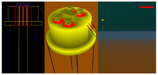
Figure 9.
Finite element model of the coupled FPSO-DAS production system.
The global analysis in the time domain is carried out under extreme storm conditions [31] (Waves: Hs = 15 m, Tz = 10.4 s) with a return period of 100 years, considering the effects of the FPSO offset (near, mean, and far conditions). With the established fully coupled model of the DAS production system, dynamic behaviors of the riser system (covering the rigid riser and the flexible jumper), the artificial seabed, and the mooring system are evaluated using irregular wave analysis. A slow drift extreme offset of 8% of water depth is adopted to simulate wave frequency motion responses of the FPSO, in combination with the Response Amplitude Operators (RAOs). The irregular wave history, depicted in Figure 10a, is generated by using the JONSWAP wave model. The current profile versus water depth is given in Figure 10b. It is assumed that surface waves and currents are collinear to consider the most severe condition.
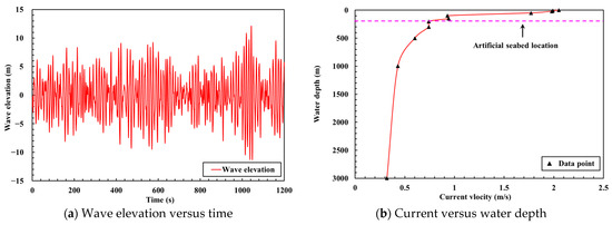
Figure 10.
Time history of wave elevation (a) and current profile (b).
3.2. Global Analysis
The vital global analysis results in relation to the survival analysis and artificial seabed stability are presented in the following sections.
3.2.1. Survival Analysis
In a previous work [33], the flexible jumper length was selected in consideration of both the safety and economy of the DAS production system. On this basis, departure angles at the top and bottom ends of the flexible jumper under extreme storm conditions are illustrated in Figure 11, with the FPSO positioned at near, mean, and far offsets, respectively. Results indicate that the departure angle variations at the bottom end are far smaller than that at the top end for different FPSO offset cases. Hence, it can be confirmed that, with the utilization of the flexible jumper, the artificial seabed is effectively de-coupled from the motion responses of the FPSO. In addition, the minimum bend radius, which occurs around the middle parts of the jumpers, can well meet the minimum requirements of 3.3 m for different FPSO offsets.
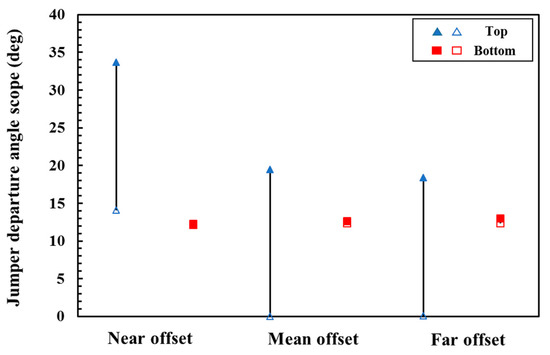
Figure 11.
Jumper departure angle for different offset cases.
After that, the dynamic performance of the rigid riser is assessed in regard to the mechanical and motion behaviors. The maximum stress of the riser versus the axial length is presented in Figure 12a, with the FPSO located at near, mean, and far offsets, respectively. Results show that the strength of the riser meets the requirement of the allowable maximum stress depicted in the figure, and the offset of the FPSO has limited effects on the mechanical behavior of the riser. In addition, higher stresses are observed near the top stress joint and the keel joint, to which more attention should be paid in the design process of the riser system. By contrast, as depicted in Figure 12b, the results show that there is a noticeable correlativity between the dynamic motions of the riser and the FPSO offset. The displacement of the riser is at a maximum when the FPSO is positioned at the far offset.
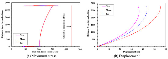
Figure 12.
The maximum stresses (a) and displacements (b) of the riser for different FPSO offset cases.
The motion scopes of the artificial seabed under extreme storm conditions are presented in Table 3. Higher surge and pitch motion amplitudes, induced by the effects of the FPSO offset, can be found when the FPSO is at the far offset. By contrast, heave motions of the artificial seabed behave insensitively to the variation in FPSO offsets. In addition, from the statistical results for the motion scopes of the artificial seabed in Table 3, it can be confirmed that both the decoupled effects of the flexible jumper and the location of the artificial seabed (200 m below M.W.L), on which the direct wave and surface current loading is minimized, contribute to the limited motion responses. Hence, the quasi-static response characteristics of the DAS production even under extreme storm conditions are proven.

Table 3.
Statistical results for motion scopes of the artificial seabed.
For the MCP and IBCs of the artificial seabed, the temporal motion responses in surge and heave directions are given in Figure 13. Results show that the IBC is guided by the MCP and moves collectively with the MCP in the horizontal span, thus reducing the clashing risk, while it is effectively decoupled from the MCP in the heave motion. In this context, the heave motion scope of the IBC is far smaller compared with that of the MCP, which will benefit the rigid riser that is quite sensitive to vertical motion.
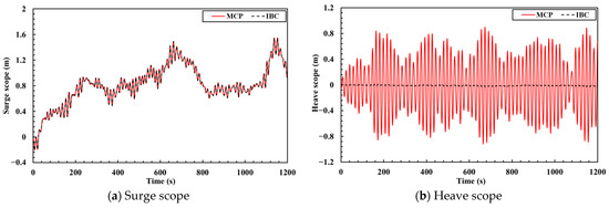
Figure 13.
Surge (a) and heave (b) scopes of the MCP and the IBC.
The performance of the mooring system with different FPSO offsets is summarized in Table 4. The maximum offsets of the artificial seabed are all kept below 2% of water depth even under extreme storm conditions, which demonstrates the favorable station-keeping ability of the mooring system. In addition, the safety factors of the mooring tether are all kept above 1.67 for different FPSO offsets [34].

Table 4.
Mooring system performance for different FPSO offsets.
3.2.2. Artificial Seabed Stability
With respect to the intact conditions, the dynamic stability of the artificial seabed can be illustrated by the survival analysis results given in Table 3. However, there are many potential causes of mooring failures that can be divided into three categories [35,36,37], namely, design/fabrication, degradation, and one-off events. Hence, it is necessary to carry out the stability analysis of the artificial seabed for damaged conditions.
In a previous work [38], the effects of tether failure on artificial seabed stability were investigated with different mooring patterns. However, the crucial transient effects induced by tether failure were not considered. In this paper, both the transient analysis and normal analysis methods, in which the tether failure occurs before the simulation begins, are applied.
The following three cases are defined, in consideration of the effects of the mooring system failure scenario.
- Case 1: One tether, which is located at the flexible jumper side, fails.
- Case 2: One tether, which is opposite the flexible jumper, fails.
- Case 3: Two tethers, which are on the diagonal, fail at the same time.
Figure 14 and Figure 15 present the motion responses of the MCP and the top tension of the remaining tethers obtained by different methods in Case 1. From the figures, an obvious mutation can be observed during the simulation when the transient analysis method is applied. For instance, compared with those provided by the normal analysis method, the maximums of the results increase sharply by 9.87% in surge and 21.63% in the top tension of the tether near the failed tether, respectively. The results show that the transient analysis method tends to provide more safety than the normal analysis method does. In addition, the top tension on the remaining tether near the fractured tether increases more significantly in comparison with that on the tether opposite the failure position, which is considered the critical tether under damage conditions and has the potential to fail sequentially.
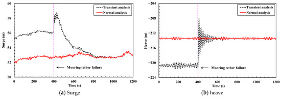
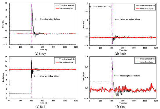
Figure 14.
Temporal motion responses of the MCP provided by the transient analysis and the normal analysis in Case 1.
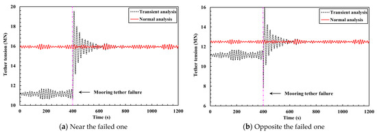
Figure 15.
Temporal top tension of the remaining tethers that are opposite the flexible jumper.
Figure 16 presents the relative motion responses of the MCP and the IBC in heave and pitch directions in Case 1. With the decoupled effects in the vertical direction provided by the multi-body design scheme, the heave motion of the IBC is slightly influenced by tether failure, which will benefit the integrity of the riser even under mooring system failure conditions. However, due to the forces transferred from the MCP, the pitch motion of the IBC is significantly affected when tether failure occurs.
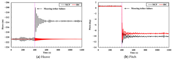
Figure 16.
Heave and pitch motions of the MCP and IBC in Case 1.
Table 5 presents the statistical results for the static motions of the MCP after one or two tethers failure occurs, as defined in the three cases. When one tether failure occurs (Cases 1 and 2), the rotational motion responses of the MCP will increase sharply. In contrast, the surge amplitudes will decrease due to the substantial increases in tensions on the remaining tethers. However, when two opposite tethers fail at the same time (Case 3), the MCP remains flat and moves up in the vertical direction.

Table 5.
Statistical results for the MCP static motions with one or two failed tethers.
In consideration of the large roll and pitch motions resulting from tether failure in Cases 1 and 2, the rigid risers tensioned by IBCs will also be seriously affected; for instance, high stress and unacceptable upper flex joint angle may occur, and the risers may even be damaged under worse conditions. In this context, the mooring pattern with eight tethers divided into four groups is considered a better choice for the safety of the DAS production system.
4. Conclusions and Future Work
This article has deeply analyzed and discussed the merits and demerits of the existing DW & UDW field development solutions, i.e., dry tree and wet tree development solutions. It is found that conventional dry tree development solutions based on the Spar and TLP technology are ‘hamstrung’ with the increase in water depth. It is observed that offshore petroleum companies prefer the wet tree development solution by default at water depths over 6000 ft at the sacrifice of the high flow assurance requirements as well as the high drilling and workover costs.
Aiming at overcoming the limitations of the dry tree and wet tree development solutions, the DAS production concept is proposed by zeroing in on the critical issues of well access and riser design, has been proposed and developed. It can be found that the DAS production system offers improved technical, economic, and safety performance. In particular, the DAS production system prompts DW & UDW fields to develop by cost-effective and proven shallow-water-rated well-completion equipment and technology. In addition, the MCP guides the IBCs and TTRs, constraining all TTRs to move collectively and thus reducing the clashing risk. The global analysis results have demonstrated and confirmed the important quasi-static feature of the DAS production system, on account of the artificial seabed location as well as the decoupling effect of flexible jumpers. Thus, the artificial seabed is able to offer favorable stability even under extreme storm conditions.
In all, the DAS production system proves to be a feasible and competitive solution to cost-effective DW & UDW field developments. In addition, the developed method and obtained findings also have a wide range of applications in the analysis aspect of the FSHR due to the comparable design philosophy.
It is worth noting that, so far conceptual design and analysis [27,31,33], systematical investigations on multi-objective optimization [24,39,40], drift-off warning analysis [41,42], hydrodynamic characteristics [43] and risk assessment [25,26] in relation to the DAS production system have been conducted.
However, the latest research results [44] show that the Internal Solitary Wave (ISW) has become the key environmental factor to affect the dynamic behaviors of the DAS production system, which can induce sudden strong currents throughout the whole water depth during its propagation process, and lead to offshore operation accidents. In addition, design on the artificial seabed will become more complicated when the DAS production system is applied for large oil and gas field developments. In the near future, relevant studies with respect to the effects of the ISWs on the DAS production system and the design improvement of the artificial seabed will be given great emphasis.
Author Contributions
Conceptualization, methodology, funding acquisition, project administration, and writing—original draft preparation, X.Z.; conceptualization and methodology, F.L.; formal analysis, figures, and writing—review and editing, Q.D.; literature search, and writing—review and editing, Y.G.; resources and supervision, Y.H. All authors have read and agreed to the published version of the manuscript.
Funding
This research is funded by the National Natural Science Foundation of China (No. 52171249) and the Fundamental Research Funds for the Central Universities (DUT22LK26).
Institutional Review Board Statement
Not applicable.
Informed Consent Statement
Not applicable.
Data Availability Statement
Not applicable.
Acknowledgments
Not applicable.
Conflicts of Interest
The authors declare no conflict of interest.
Nomenclature
| DAS | Deepwater Artificial Seabed | DW | Deepwater |
| UDW | Ultra-Deepwater | FPSO | Floating Production Storage and Offloading |
| BOE | Barrels of Oil Equivalent | FHF | Floating Host Facility |
| TLP | Tension Leg Platform | TSP | Truss-pontoon Semisubmersible Platform |
| Min Doc | Minimum Deepwater Operating Concept | EDP | Extendable Draft Platform |
| DTP | Deepwater Tumbler Platform | G-Spar | Geometric Spar |
| CT-Spar | Cell-Truss Spar | DDMS | Deep Draft Multi-Spar |
| FSHR | Free-Standing Hybrid Riser | SLOR | Single Line Offset Riser |
| COR | Concentric Offset Riser | BHOR | Bundle Hybrid Offset Riser |
| HRT | Hybrid Riser Tower | BSR | Buoy for Supporting Risers |
| DVA | Direct Vertical Access | MODU | Mobile Offshore Drilling Unit |
| CAPEX | Capital Expenditures | OPEX | Operating Expenditures |
| EPS | Early Production System | GoM | Gulf of Mexico |
| TTR | Top Tensioned Riser | ART | Aircan Riser Tensioner |
| HPT | Hydro-Pneumatic Tensioner | MCP | Mono-Colum Platform |
| IBC | Internal Buoyancy Can | M.W.L | Mean Water Level |
| BOP | Blowout Preventer | SCS | South China Sea |
| RAO | Response Amplitude Operator | ISW | Internal Solitary Wave |
References
- Wood, M. Global Deepwater: The State of the Industry; Wood Mackenzie: Edinburgh, Scotland, 2019. [Google Scholar]
- Barton, C.; Albaugh, E.; Davis, D. Deepwater Technologies & Solutions for Concept Selection; Wood Group Mustang: Calgary, AB, Canada, 2019. [Google Scholar]
- Srinivasan, N.; Chakrabarti, S.; Radha, R. Response analysis of a truss-pontoon semisubmersible with heave-plates. J. Offshore Mech. Arct. Eng. Trans. ASME 2006, 128, 100–107. [Google Scholar] [CrossRef]
- Ocker, C.; Bordlee, C. Mirage field multi-column deep draft floating platform: Graving dock construction and hull fabrication. In Proceedings of the Offshore Technology Conference, Houston, TX, USA, 3–6 May 2010; pp. 3199–3216. [Google Scholar]
- Xu, Q.; Xu, L.X. An introduction to extendable draft platform (EDP). In Proceedings of the 14th International Offshore and Polar Engineering Conference (ISOPE 2004), Toulon, France, 23–28 May 2004; pp. 546–550. [Google Scholar]
- Noce, R.; Husem, I. A robust and flexible dry tree semisubmersible drilling and production platform. In Proceedings of the Offshore Technology Conference, Houston, TX, USA, 6–9 May 2013. [Google Scholar]
- Jiang, Z.; Xie, B.; Cui, W.; Du, Q.; Tian, X. A study on the heave performance and loads of the critical connections of a novel dry tree semisubmersible concept using numerical and experimental methods. Ocean Eng. 2016, 124, 42–53. [Google Scholar] [CrossRef]
- Guo, J.; Lv, H.; Xie, W. Study on heave motion performance of a new dry tree semi-submersible production platform. Ocean. Eng. 2021, 39, 9–19. (In Chinese) [Google Scholar] [CrossRef]
- Guo, J.; Lv, H.; Xie, W.; Han, X. Motion performance of a new vertically-coupled multi-body low motion semi-submersible platform. J. Ship Mech. 2022, 26, 1290–1302. [Google Scholar] [CrossRef]
- Zhang, F.; Yang, J.; Li, R.; Chen, G. Experimental investigation on hydrodynamic behavior of the geometric spar platform. China Ocean Eng. 2006, 20, 213–224. [Google Scholar] [CrossRef]
- Zhang, F.; Yang, J.; Li, R.; Chen, G. Numerical and experimental research on the global performances of cell-truss spar platform. China Ocean Eng. 2007, 21, 561–576. [Google Scholar]
- Li, B.-B.; Ou, J.-P. Concept design of a new deep draft platform. J. Mar. Sci. Appl. 2010, 9, 241–249. [Google Scholar] [CrossRef]
- Peng, C.; Kuang, X.; Hao, L.; Qiang, Z. The hydrodynamic performances of one kind Spar-TCell Spar. China Offshore Platf. 2009, 24, 31–35. [Google Scholar] [CrossRef]
- Yu, W.; Huang, W. A new concept of spar and its hydrodynamic analysis. In Proceedings of the twentieth (2010) international offshore and polar engineering conference (ISOPE-2010 Beijing), Beijing, China, 20–25 June 2010; pp. 514–520. [Google Scholar]
- Chang, S.; Huang, W.; Yu, W. A new concept spar platform s-spar and its hydrodynamic analysis in time domain. J. Ship Mech. 2020, 24, 776–786. [Google Scholar] [CrossRef]
- Saad, A.C.; Vilain, L.; Loureiro, R.R. Motion behavior of the mono-column FPSO Sevan Piranema in Brazilian waters. In Proceedings of the Offshore Technology Conference 2009 (OTC.09), Houston, Texas, USA, 4–7 May 2009; pp. 1–9. [Google Scholar]
- Lamport, W.B.; Josefsson, P.M. The next generation of round fit-for purpose hull from FPSOs offers advantages over traditional ship-shaped hull forms. In Proceedings of the 2008 Deep Gulf Conference, New Orleans, LA, USA, 9–11 December 2008. [Google Scholar]
- Bai, Y.; Bai, Q. Subsea Pipelines and Risers; Elsevier Science Ltd: Oxford, UK, 2005; pp. 809–812. [Google Scholar]
- Zhang, C.; Lu, L.; Cao, Q.; Cheng, L.; Tang, G. Nonlinear motion regimes and phase dynamics of a free standing hybrid riser system subjected to ocean current and vessel motion. Ocean Eng. 2022, 252, 111197. [Google Scholar] [CrossRef]
- Franciss, R.; Gonzales, E.C.; Almeida, J.; Araújo, J.; Fernandes, A.C. Alternative method of buoy supporting riser (BSR) installation. In Proceedings of the 30th International Conference on Offshore Mechanics and Arcitic Engineering, Rotterdam, Rotterdam, The Netherlands, 19–24 June 2011. [Google Scholar]
- Claro, C.; Cruz, I.; Karunakaran, D.; Hepener, G.; Ji, C.; Ding, Y.; Wu, C.; Scharnke, J.; de Wilde, J.; Franciss, R. Hydrodynamic behavior of an ultra-deep water decoupled buoy support risers. In Proceedings of the 35th ASME International Conference on Ocean, Offshore and Arctic Engineering, Busan, South Korea, 19–24 June 2016. [Google Scholar]
- Lim, F. Dry or wet trees in deepwater developments from a riser system perspective. In Proceedings of the Third International Deep-Ocean Technology Symposium, Beijing, China, 28 June–1 July 2009; pp. 50–54. [Google Scholar]
- Adumene, S.; Khan, F.; Adedigba, S.; Mamudu, A.; Rosli, M.I. Offshore oil and gas development in remote harsh environments: Engineering challenges and research opportunities. Saf. Extrem. Environ. 2022, 1–17. [Google Scholar] [CrossRef]
- Wu, J.; Zhen, X.; Liu, G.; Huang, Y. Optimization design on the riser system of next generation subsea production system with the assistance of DOE and surrogate model techniques. Appl. Ocean Res. 2019, 85, 34–44. [Google Scholar] [CrossRef]
- Zhen, X.; Moan, T.; Gao, Z.; Huang, Y. Risk assessment and reduction for an innovative subsurface well completion system. Energies 2018, 11, 1306. [Google Scholar] [CrossRef]
- Zhen, X.; Vinnem, J.E.; Han, Y.; Peng, C.; Yang, X.; Huang, Y. New risk control mechanism for innovative deepwater artificial seabed system through online risk monitoring system. Appl. Ocean Res. 2020, 95, 102054. [Google Scholar] [CrossRef]
- Zhen, X.; Han, Y.; Duan, Q.; Wu, J.; Huang, Y. Development of next generation subsea production system (NextGen SPS) design and analysis for ultra-deepwater applications. Underw. Technol. 2020, 37, 111–117. [Google Scholar] [CrossRef]
- Chedzoy, C.; Lim, F. Design challenges of deepwater dry tree riser systems for different vessel types. In Proceedings of the 13th International Offshore and Polar Engineering Conference (ISOPE-2003), Honolulu, HI, USA, 25–30 May 2003; pp. 76–82. [Google Scholar]
- Song, R.; Stanton, P. Advances in deepwater steel catenary riser technology state-of-the-art: Part 1-design. In Proceedings of the 26th International Conference on Offshore Mechanics and Arctic Engineering, San Diego, CA, USA, 10–15 June 2007; pp. 331–344. [Google Scholar]
- Vinnem, J.; Røed, W. Offshore Risk Assessment; Springer Verlag: London, UK, 2020; p. 577. [Google Scholar]
- Zhen, X. Investigation on Coupled Motion and Risk Assessment of an Innovative Subsurface Production System. Ph.D. Thesis, Dalian University of Technology, Dalian, China, 2016. [Google Scholar]
- Orcina Led. Orcaflex Manual Version 11.0 f; Orcina Ltd: Cumbria, UK, 2020. [Google Scholar]
- Zhen, X.; Han, Y.; Huang, Y.; Yao, J.; Wu, J. Analytical approach for the establishment of critical length criterion for the safe and economical design of the flexible jumper in deepwater applications. Appl. Ocean Res. 2018, 75, 193–200. [Google Scholar] [CrossRef]
- American Petroleum Institute; API R P. 2SK. Design and Analysis of Station Keeping Systems for Floating Structures; American Petroleum Institute: New York, NY, USA, 2005. [Google Scholar]
- American Bureau of Shipping. Guidance Notes on Mooring Integrity Management; American Bureau of Shipping: Houston, TX, USA, 2018. [Google Scholar]
- AMOG Consulting. Mooring Integrity Management Guidelines; Deepstar Project: CTR-11405; American Petroleum Institute: Washington, DC, USA, 2013. [Google Scholar]
- Ma, K.; Duggal, A.; Smedley, P.; Hostis, D.; Shu, H. A historical review on integrity issues of permanent mooring systems. In Proceedings of the 45th Annual Offshore Technology Conference, Houston, Texas, USA, 6–9 May 2013. [Google Scholar]
- Zhen, X.; Duan, Q.; Han, Y.; Huang, Y. Investigations on the quasi-static stability behavior of an innovative subsurface tension leg platform in ultra-deep water (Part II). J. Ship Mech. 2022, 26, 834–842. [Google Scholar] [CrossRef]
- Wu, J.; Zhen, X.; Liu, G.; Huang, Y. Uncertain multidisciplinary design optimization on next generation subsea production system by using surrogate model and interval method. China Ocean Eng. 2021, 35, 609–621. [Google Scholar] [CrossRef]
- Wu, J. Multidisciplinary Design Optimization for Deepwater Artificial Seabed System. Ph.D. Thesis, Dalian University of Technology, Dalian, China, 2022. [Google Scholar]
- Han, Y.; Zhen, X.; Huang, Y. Drift-off warning limits for dynamically positioned FPSO and deepwater artificial seabed (DAS) coupling system. Ocean Eng. 2021, 237, 109662. [Google Scholar] [CrossRef]
- Han, Y.; Zhen, X.; Moan, T.; Huang, Y. Real time prediction of operational safety limits for dynamic positioning of an FPSO in a deepwater artificial seabed system. Mar. Struct. 2021, 80, 103093. [Google Scholar] [CrossRef]
- Yao, J.; Zhen, X.; Huang, Y.; Wang, W. Numerical investigation on hydrodynamic characteristics of immersed buoyant platform. J. Mar. Sci. Eng. 2021, 9, 168. [Google Scholar] [CrossRef]
- Duan, Q.; Zhen, X.; Huang, Y.; Yao, J.; Guo, W.; Liu, G. Experiment-based coupled dynamic analysis of submerged production platform-mooring system in internal solitary waves. Ocean Eng. 2022, 260, 112044. [Google Scholar] [CrossRef]
Disclaimer/Publisher’s Note: The statements, opinions and data contained in all publications are solely those of the individual author(s) and contributor(s) and not of MDPI and/or the editor(s). MDPI and/or the editor(s) disclaim responsibility for any injury to people or property resulting from any ideas, methods, instructions or products referred to in the content. |
© 2023 by the authors. Licensee MDPI, Basel, Switzerland. This article is an open access article distributed under the terms and conditions of the Creative Commons Attribution (CC BY) license (https://creativecommons.org/licenses/by/4.0/).